Maintaining MX2008 Cooling System Components
Replacing the MX2008 Air Filters
The MX2008, MX2010, and MX2020 routers support the same fan modules.
Removing the MX2008 Air Filter
Do not run the router for more than a few minutes without the air filter in place.
Always keep the air filter in place while the router is operating, except during replacement. Because the fans are very powerful, they could pull small bits of wire or other materials into the router through the unfiltered air intake. This could damage the router components.
To remove the air filter:
- Slide the air filter out of the chassis as shown in Figure 1.Figure 1: Removing the Air Filter from the Chassis
To remove the PSM air filter:
Attach an electrostatic discharge (ESD) grounding strap to your bare wrist, and connect the strap to one of the ESD points on the chassis.
Loosen the two captive screws located on either side of the air filter and pull slightly out of the chassis.
CAUTION:Do not run the router for more than 2 minutes without the air filter in place.
Grasp the PSM air filter, and pull the air filter straight out from the chassis.
Slide the air filter out of the chassis as shown in Figure 2.
Note:The AC–powered MX2008 router has the same air filter.
Figure 2: Removing the PSM Air Filter from the Chassis
To remove the PSM air filter—MX2000-FLTR-PWR for a chassis with the DC PDM (240 V China) or universal HVAC/HVDC PDM installed:
Attach an electrostatic discharge (ESD) grounding strap to your bare wrist, and connect the strap to one of the ESD points on the chassis.
Remove the screws from the mechanical interlock bracket to remove it. See Figure 3 and Figure 4 .
Figure 3: Removing the bracket from the PDM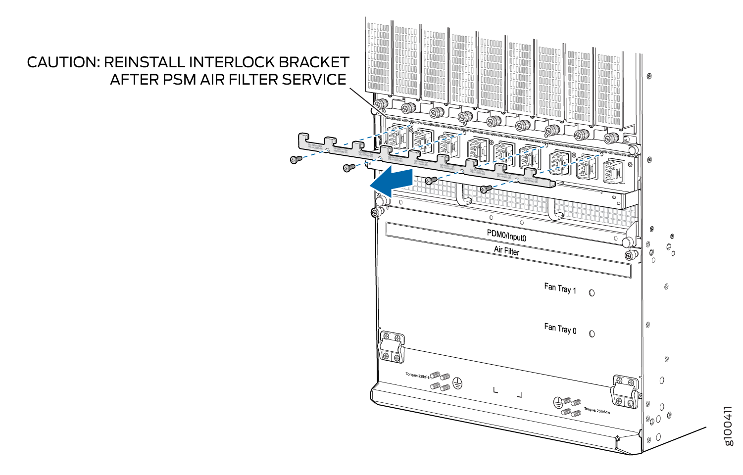 Figure 4: Removing the Bracket from the Universal (HVAC/HVDC) PDM
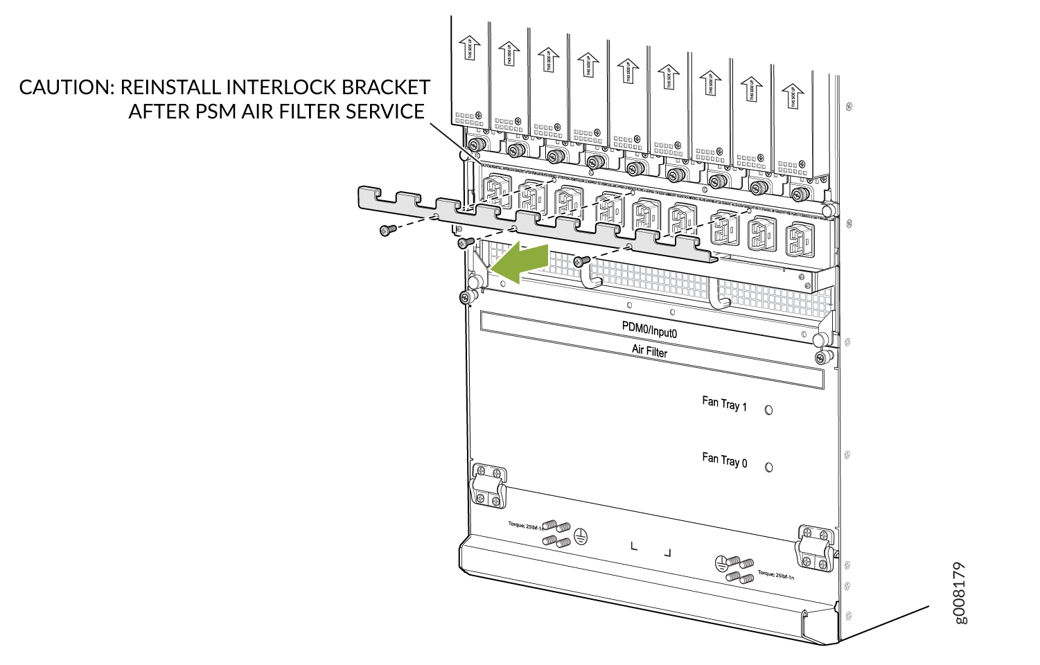
Loosen the two captive screws located on either side of the air filter and pull slightly out of the chassis.
CAUTION:Do not run the router for more than 2 minutes without the air filter in place.
Grasp the PSM air filter, and pull the air filter straight out from the chassis.
Slide the air filter out of the chassis as shown in Figure 5 and Figure 6.
Figure 5: Removing the PSM Air Filter from the Chassis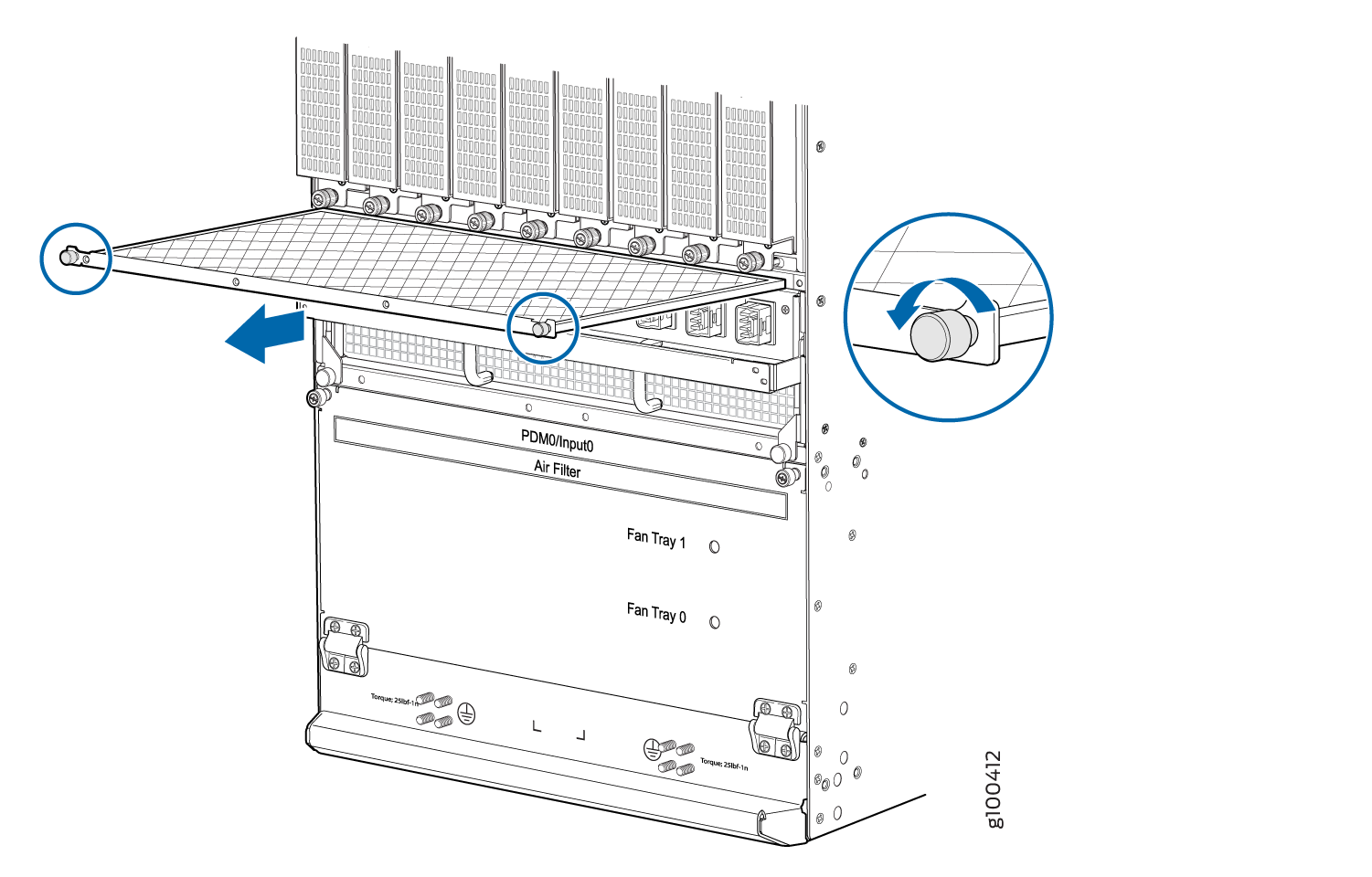 Figure 6: Removing the PSM (for the Universal HVAC/HVDC) Air Filter from the Chassis
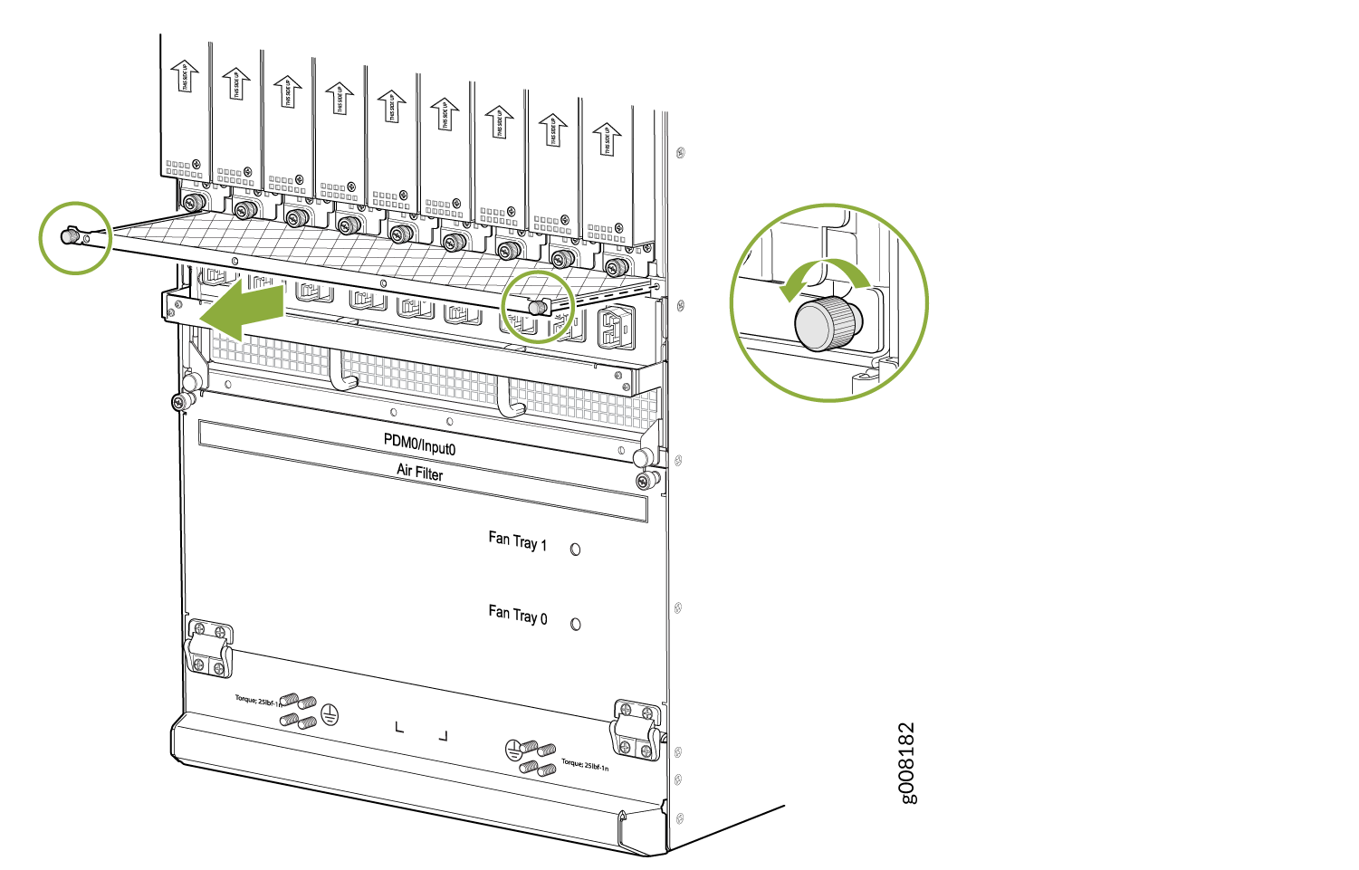
Make sure to re-install the mechanical interlock bracket after you remove the filter. Secure the screws on the mechanical interlock bracket.
Figure 7: Installing the Mechanical Interlock Bracket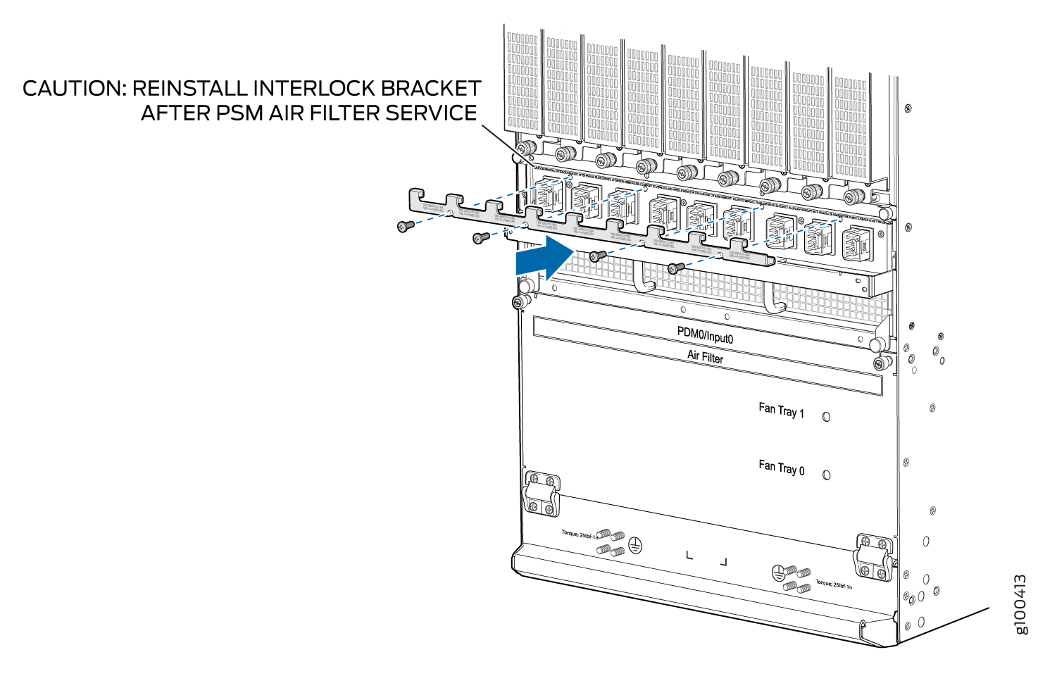 Figure 8: Installing the Mechanical Interlock Bracket (with Universal HVAC/HVDC PSM Installed)
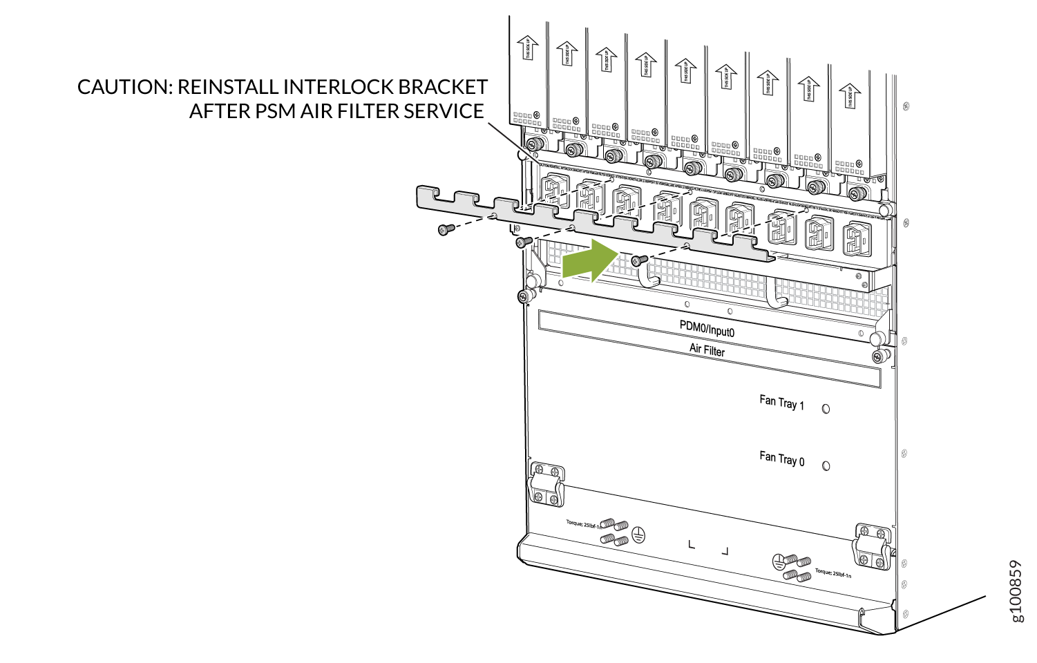
Installing the MX2008 Air Filter
To install the air filter:
- Attach an electrostatic discharge (ESD) grounding strap to your bare wrist, and connect the strap to one of the ESD points on the chassis.
- Ensure that the air filter is right side up.
- Open the fan tray and air filter access door, located at the bottom of the chassis.
- Grasp the handle on the air filter and insert into the chassis until it stops (see Figure 9).
- Close the access door and tighten the two captive screws to secure.
- Lower the cable manager back into position, and rearrange the cables in the cable manager.
To install the PSM air filter:
Attach an electrostatic discharge (ESD) grounding strap to your bare wrist, and connect the strap to one of the ESD points on the chassis.
Ensure that the air filter is right side up.
Grasp the PSM air filter and insert into the chassis until it stops, (see Figure 10).
Tighten the two captive screws to secure.
Note:The AC–powered MX2008 router has the same air filter.
To install the PSM air filter—MX2000-FLTR-PWR for chassis with 240 V China power supplies and universal (HVAC/HVDC) power supplies:
Attach an electrostatic discharge (ESD) grounding strap to your bare wrist, and connect the strap to one of the ESD points on the chassis.
Unscrew the mechanical interlock bracket from the PDM (see Figure 11 and Figure 12).
Figure 11: Removing the Bracket from the 240 V China PDMFigure 12: Removing the Bracket from the Universal (HVAC/HVDC) PDMEnsure that the air filter is right side up.
Grasp the PSM air filter and insert into the chassis until it stops, (see Figure 13).
Tighten the two captive screws to secure.
Figure 13: Installing the PSM Filter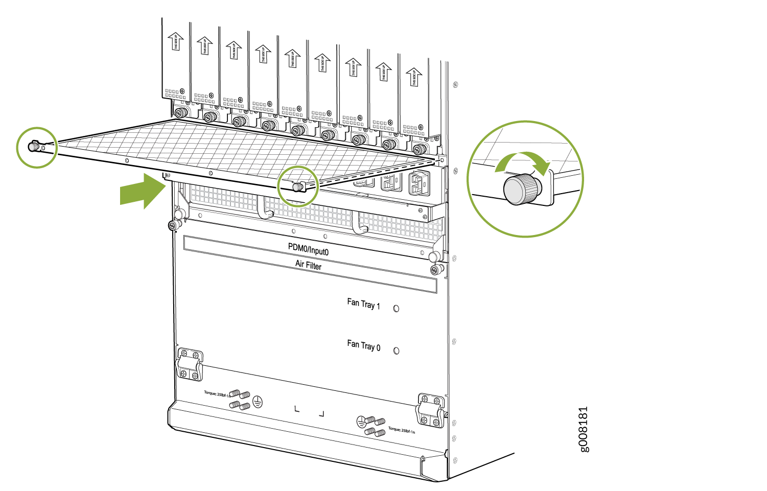
Install the mechanical interlock bracket and tighten the screws. See Figure 14 and Figure 15.
Figure 14: Installing the Bracket (with 240 V China PSM Installed)Figure 15: Installing the Mechanical Interlock Bracket (with Universal HVAC/HVDC PSM Installed)
Replacing an MX2008 Fan Tray
The MX2008, MX2010, and MX2020 routers support the same fan modules.
Removing an MX2008 Fan Tray
To prevent overheating, install the replacement fan tray immediately after removing the existing fan tray.
To remove the lower fan trays (see Figure 16):
Before removing a fan tray, make sure the fan blades have stopped completely.
Installing an MX2008 Fan Tray
This topic describes how to install the lower fan trays in a MX2008. This procedure applies to both the standard fan tray and the optimized power fan tray.
To install the lower fan tray (see Figure 17):