Help us improve your experience.

Let us know what you think.

Do you have time for a two-minute survey?


Unpack the MX10004 Router

SUMMARY Unpack the router using the recommended tools and following the recommended procedure.

Unpack the MX10004 Shipping Pallet

Gather the following tools and parts to unpack the Juniper Networks MX10004 router:

  • Phillips (+) screwdriver, number 2

  • 1/2-in. or 13-mm open-end or socket wrench to remove bracket bolts from the shipping pallet

  • A box cutter or packing knife to slice open the nylon straps and tape that seal the crate and boxes

  • Blank panels to cover any slots not occupied by a component

After you prepare the installation site as described in Table 1, you can unpack the router.

The MX10004 router chassis is a rigid sheet-metal structure that houses the hardware components. The chassis ships in a cardboard box that has a two-layer wooden pallet base with foam cushioning between the layers. The router chassis is bolted to the pallet base. The carton also contains an accessory box and a rack-mount kit.

Note:

The chassis is well protected inside the shipping box. Keep it secure in its packaging until you are ready to begin installation.

The shipper has the option to either ship the front panel separately or ship it along with the chassis. If the front panel arrives with the chassis, set aside the front panel box until you are ready to verify the contents of the order. See Figure 1.
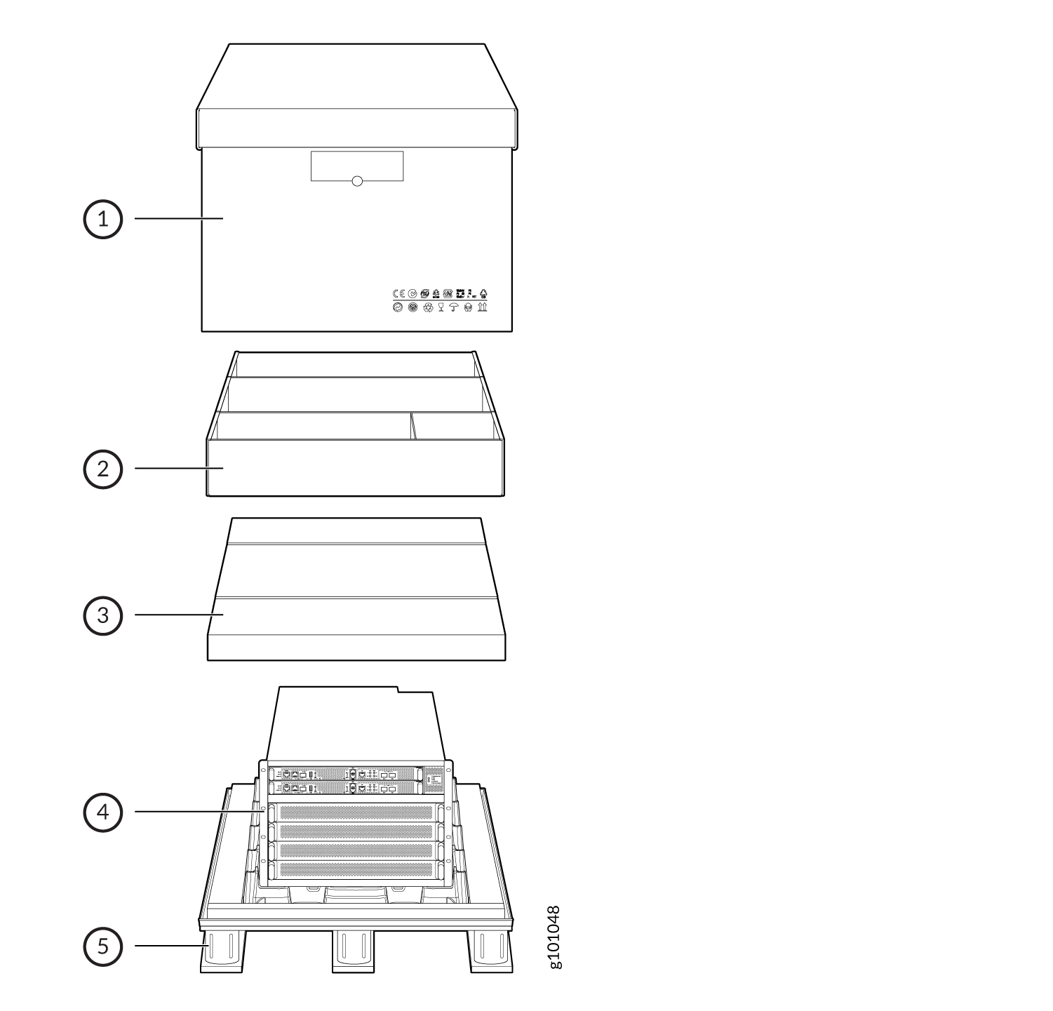
Figure 1: Shipping Crate and Accessory Box Shipping Crate and Accessory Box
  1

Cardboard shipping box

  4

MX10004 chassis

  2

Cardboard accessory box

  5

Wood pallet

  3

Foam cover


To unpack the chassis:

  1. Move the shipping box to a staging area as close to the installation site as possible. While the chassis is bolted to the pallet, you can use a forklift or pallet jack to move the shipping box. Make sure there is enough space to remove components from the chassis.
  2. Position the shipping box with the arrows pointing up.
  3. Use the box cutter to slice the nylon straps that secure the shipping box to the pallet.
  4. Lift the shipping box off the chassis.
  5. Remove the cardboard accessory box.
  6. Remove the foam padding from the top of the box.
  7. Remove the plastic cover from the router chassis.
  8. Use a mechanical lift to lift the chassis from the shipping pallet. Otherwise, unload all of the components, except the fan tray controller, and manually lift the chassis from the shipping pallet. See Figure 2 and Mount the Juniper Networks MX10004 Router Using the JNP10004-RMK-4POST Rack-Mount Kit.
    Figure 2: Lift the Chassis Off the Pallet
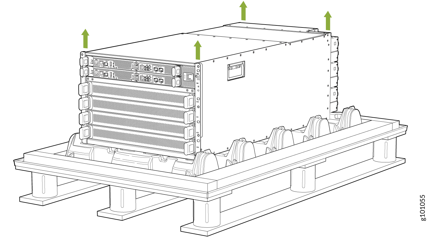
 Lift the Chassis Off the Pallet
    Note:

    The chassis has two handles that are designed for subtle positioning of the chassis. Do not lift the chassis by the handles.

  9. Unpack the accessory box and lay out the contents so that they are ready for use.
  10. Verify that your order includes all appropriate parts. See Compare the MX10004 Router Order to the Packing List and MX10004 Components and Configurations for information about base configurations and redundant configurations.
  11. Save the shipping box and packing materials to move or ship the router at a later time.

Unpack Line Cards, Routing Control Boards, and Switch Fabric Boards for the MX10004 Router

Before you unpack a component of the Juniper Networks MX10004 router:

Line cards, additional Routing Control Board (RCBs), and Switch Fabric Borad (SFBs) are field-replaceable units (FRUs) that are shipped separately from the router chassis. The housings for the RCBs and line cards are rigid sheet-metal structures that house the electronics. SFBs have an exposed printed circuit board (PCB) on one side and sheet metal on the other. All these components are shipped in a cardboard carton, secured with packing material.

CAUTION:

The components are well protected inside the shipping carton. Keep the components secured inside their packaging until you are ready to install the components in the router chassis.

To unpack an RCB, an SFB, or a line card:

  1. Move the shipping carton to a staging area as close to the installation site as possible.
  2. Position the carton so that the arrows are pointing up.
  3. Open the top flaps on the shipping carton.
  4. Pull out the packing material that holds the component in place.
  5. Remove the component from the antistatic bag.
  6. Save the shipping carton and packing materials to move or ship the RCB, SFB, or line cards later.
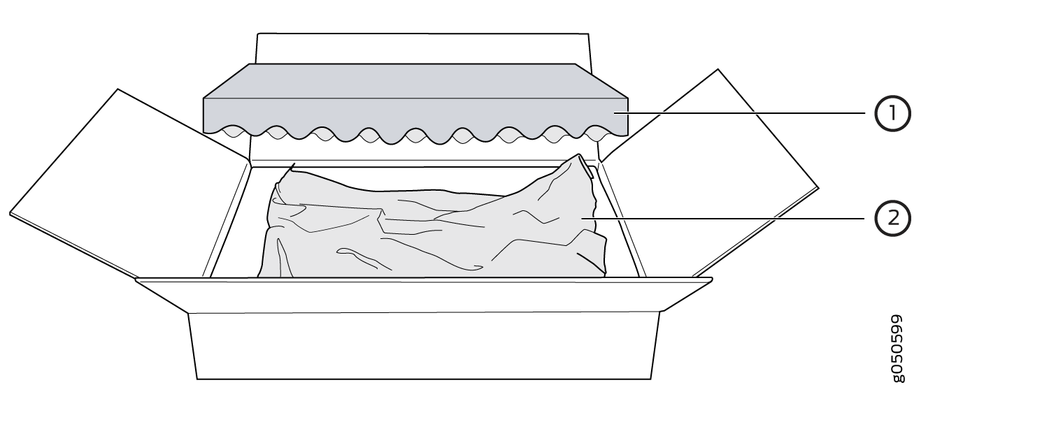
Figure 3: Unpack a Line Card Unpack a Line Card
  1

Foam packing material

  2

Paper packaging and antistatic bag

Compare the MX10004 Router Order to the Packing List

The Juniper Networks MX10004 router chassis shipment includes a packing list. Check the parts you receive in the shipping crate against the items on the packing list. The packing list specifies the part number and description of each part in your order.

If any part on the packing list is missing, contact your customer service representative, or contact Juniper Networks Customer Care from within the USA or Canada by telephone at 1-888-314-5822. For international-dial or direct-dial options in countries without toll-free numbers, see https://www.juniper.net/support/requesting-support.html.

Items that ship separately from the chassis are:

  • Line cards.

  • Chassis front door kit (JNP10004-FRNT-PNL) or JNP10004-FRPNL1 with air filter.

    Note:

    The kit is a spare part and can ship with the chassis or separately.

  • Cable management kit (JLC-CBL-MGMT-KIT).

To compare the sales order and packing list against the contents of the chassis shipping crate:

  1. Determine the configuration. See MX10004 Components and Configurations. The parts shipped depend on the configuration you order.
  2. Compare the packing list accompanying the chassis with the configuration order:
    • For MX10004-BASE configuration orders, see Table 1.

    • For MX10004-3F-BASE configuration orders, see Table 2.

    • For MX10004-PREMIUM configuration orders, see Table 3.

    • For MX10004-4F-PREM configuration orders, see Table 4.

    Table 1: MX10004-BASE Configuration Order

    Component

    MX10004 Quantity

    Chassis, including power bus (JNP10004-CHAS)

    1

    Routing Control Board (RCB) (JNP10K-RE1, JNP10K-RE1-LT, or JNP10K-RE1-128)

    1

    RCB cover (JNP10K-RE-BLNK)

    1

    Fan tray controllers (JNP10004-FTC2)

    2

    Fan trays (JNP10004-FAN2)

    2

    Power supplies:

    • JNP10K-PWR-AC3

    • JNP10K-PWR-AC2

    • JNP10K-PWR-DC2

    2

    Power supply blank cover panel (JNP10K-PWR-BLNK)

    1

    Switch Fabric Board (SFB) (JNP10004-SF2)

    5

    SFB cover (JNP10004-SF-BLNK)

    1

    Line card blank cover panel (JNP10K-LC-BLNK)

    4

    Accessory kit (see Table 5)

    1

    Rack-mount kit (see Table 6)

    1

    Front panel kit (see Table 7 or Table 8)

    1

    Documentation Roadmap Card

    1

    Table 2: MX10004-3F-BASE Configuration Order

    Component

    MX10004 Quantity

    Chassis, including power bus (JNP10004-CHAS)

    1

    Routing Control Board (RCB) (JNP10K-RE1, JNP10K-RE1-LT, or JNP10K-RE1-128)

    1

    RCB cover (JNP10K-RE-BLNK)

    1

    Fan tray controllers (JNP10004-FTC2)

    2

    Fan trays (JNP10004-FAN2)

    2

    Power supplies:

    • JNP10K-PWR-AC3

    • JNP10K-PWR-AC2

    • JNP10K-PWR-DC2

    2

    Power supply blank cover panel (JNP10K-PWR-BLNK)

    1

    Switch Fabric Board (SFB) (JNP10004-SF2)

    3

    SFB cover (JNP10004-SF-BLNK)

    3

    Line card blank cover panel (JNP10K-LC-BLNK)

    4

    Accessory kit (see Table 5)

    1

    Rack-mount kit (see Table 6)

    1

    Front panel kit (see Table 7 or Table 8)

    1

    Documentation Roadmap Card

    1

    Table 3: MX10004-PREMIUM Configuration Order

    Component

    MX10004 Quantity

    Chassis, including power bus (JNP10004-CHAS)

    1

    Routing Control Board (RCB) (JNP10K-RE1, JNP10K-RE1-LT, or JNP10K-RE1-128)

    2

    Fan tray controllers (JNP10004-FTC2)

    2

    Fan trays (JNP10004-FAN2)

    2

    Power supplies:

    • JNP10K-PWR-AC3

    • JNP10K-PWR-AC2

    • JNP10K-PWR-DC2

    3

    Switch Fabric Board (SFB) (JNP10004-SF2)

    6

    Line card blank cover panel (JNP10K-LC-BLNK)

    4

    Accessory kit (see Table 5)

    1

    Rack-mount kit (see Table 6)

    1

    Front panel kit (see Table 7 or Table 8)

    1

    Documentation Roadmap Card

    1

    Table 4: MX10004-4F-PREM Configuration Order

    Component

    MX10004 Quantity

    Chassis, including power bus (JNP10004-CHAS)

    1

    Routing Control Board (RCB) (JNP10K-RE1, JNP10K-RE1-LT, or JNP10K-RE1-128)

    2

    Fan tray controllers (JNP10004-FTC2)

    2

    Fan trays (JNP10004-FAN2)

    2

    Power supplies:

    • JNP10K-PWR-AC3

    • JNP10K-PWR-AC2

    • JNP10K-PWR-DC2

    3

    Switch Fabric Board (SFB) (JNP10004-SF2)

    4

    SFB cover (JNP10004-SF-BLNK)

    2

    Line card blank cover panel (JNP10K-LC-BLNK)

    4

    Accessory kit (see Table 5)

    1

    Rack-mount kit (see Table 6)

    1

    Front panel kit (see Table 7 or Table 8)

    1

    Documentation Roadmap Card

    1

  3. Compare the contents of the accessory kit with Table 5.
    Table 5: MX10004 Accessory Kit

    Component

    Quantity

    AC Configurations

    DC Configurations

    Warranty card

    1

    1

    End User License Agreement (EULA)

    1

    1

    Electrostatic discharge (ESD) wrist strap with cable

    1

    1

    Media kit (flash drives and PCMCIA card adapter)

    1

    1

    Chassis ground lug (2-hole, 10-32, 6 AWG)

    1

    1

    Power cord retainer clips

    6

    DC terminal lugs (2-hole, 10-32, 4 AWG)

    PREMIUM configurations = 24

    BASE configurations = 16

    Antistatic bags

    4

    4

    Note:

    We no longer include a DB-9 to RJ-45 cable or a DB-9 to RJ-45 adapter with a CAT5E copper cable as part of the device package. If you require a console cable, you can order it separately with the part number JNP-CBL-RJ45-DB9 (DB-9 to RJ-45 adapter with a CAT5E copper cable).

  4. Compare the contents of the rack-mount kit with Table 6.
    Table 6: MX10004 Rack-Mount Kit

    Component

    Quantity

    Mounting tray

    1

    Mounting blades

    2

    Safety restraint

    1

    Phillips flat-head screws (8-32 x .375 in.)

    12

  5. Compare the contents of the ESD front door kit with Table 7 or Table 8.
    Table 7: JNP10004-FRNT-PNL Front Door Kit

    Component

    Quantity

    Front door

    1

    Table 8: JNP10004-FRPNL1 Front Door Kit with Air Filter

    Component

    Quantity

    Front door with air filter

    1

    Line-card handle extensions

    8

    Cable tray

    4

    Cable seals

    3

Register Products—Mandatory to Validate SLAs

Register all new Juniper Networks hardware products and changes to an existing installed product using the Juniper Networks website to activate your hardware replacement service-level agreements (SLAs).

CAUTION:

Register product serial numbers on the Juniper Networks website. Update the installation base data if any addition or change to the installation base occurs or if the installation base is moved. Juniper Networks is not responsible for not meeting the hardware replacement service-level agreement for products that do not have registered serial numbers or accurate installation base data.

Register your product(s) at https://tools.juniper.net/svcreg/SRegSerialNum.jsp.Update your installation base at https://www.juniper.net/customers/csc/management/updateinstallbase.jsp.