Help us improve your experience.

Let us know what you think.

Do you have time for a two-minute survey?


EX4400 System Overview

EX4400 Switches Hardware Overview

The Juniper Networks® EX4400 Switch is Juniper's first cloud-ready switch. The EX4400 switch provides connectivity for high-density environments and scalability for growing networks. You typically use EX4400 switches in large branch offices, campus wiring closets, and data centers. In data centers, you can position EX4400 switches as top-of-rack switches to provide connectivity for all devices in the rack.

We ship the EX4400 switches:

  • With RJ-45 ports that support IEEE 802.3bt Power over Ethernet (PoE-bt), fast Power over Ethernet (PoE), and Perpetual PoE in EX4400-24P, EX4400-24MP, EX4400-48P, and EX4400-48MP switches

  • With one hot-swappable AC or DC power supply. You can order an additional power supply and power cord separately to provide 1+1 redundancy.

  • With dual hot-swappable fan trays that provide front-to-back or back-to-front airflow and maintain high system availability.

  • With a slot to install an optional extension module.

You can manage EX4400 switches by using the CLI or J-Web. You can also use Juniper Mist™ to manage EX4400 switches that you deploy in a cloud network.

Here's a brief video overview of the EX4400 switches except EX4400-24MP, EX4400-48MP, and EX4400-24X switches:

Here's a brief video overview of the EX4400-24MP and EX4400-48MP switches:

Here's a brief video overview of the EX4400-24X switch:

Benefits of the EX4400 Switch

Cloud readiness—EX4400 switches are our first cloud-ready switches. You can deploy the switches and manage them by using Juniper Mist.

Support for Virtual Chassis—EX4400 switches support Virtual Chassis technology. You can interconnect up to 10 EX4400 switches to form a Virtual Chassis.

Support for channelization—You can channelize the QSFP28 ports on the EX4400 switch and increase the number of interfaces.

Support for MACsec and EVPN-VXLAN architecture—EX4400 switches support IEEE 802.1AE Media Access Control Security (MACsec) and EVPN-VXLAN. Support for MACsec and EVPN-VXLAN ensures link-layer data confidentiality, data integrity, and data origin authentication to help secure deployments in enterprise multicloud deployments. The RJ-45, SFP, and SFP+ network ports and the ports in the 4x25GbE SFP28 extension module support MACsec with AES-128, AES-256, AES-XPN-128, and AES-XPN-256 encryption.

Support for IEEE 802.3bt Power over Ethernet (PoE-bt)—The RJ-45 ports in EX4400-24P, EX4400-24MP, EX4400-48P, and EX4400-48MP switches support IEEE 802.3bt (PoE-bt), providing power of up to 90 W per port.

Support for fast PoE—The RJ-45 ports in EX4400-24P, EX4400-24MP, EX4400-48P, and EX4400-48MP switches support fast PoE. Fast PoE delivers PoE power to connected devices even before the switch is fully operational. You'll find this feature beneficial when your connected devices need only power, not network connectivity.

Support for Perpetual PoE—The RJ-45 ports in EX4400-24P, EX4400-24MP, EX4400-48P, and EX4400-48MP switches support perpetual PoE. This feature provides uninterrupted power to connected devices even when the switch is rebooting.

Compact solution—The EX4400 switch is a modular single rack unit (1-U) device that is an apt solution for crowded wiring closets and access switch locations. The switch provides carrier-class reliability of modular systems with the economics and flexibility of stackable platforms.

High availability—EX4400 switches provide high availability through redundant power supplies and fans, graceful Routing Engine switchover (GRES), and nonstop bridging (NSB) and nonstop active routing (NSR) when deployed in a Virtual Chassis configuration.

Software and Hardware Features

Juniper Networks EX Series Switches run Junos® operating system (Junos OS), which provides Layer 2 and Layer 3 switching, routing, and security services. We've listed the first Junos OS release, hardware features, and software features supported on the models Table 1.

Table 1: First Junos OS Release, Hardware Features, and Software Features Supported on EX4400 Switch Models

Switch Model

Aggregate Throughput

First Junos OS Release Supported

Hardware Features

Software Features

EX4400-24T and EX4400-24P

324 Gbps (unidirectional)

648 Gbps (bidirectional)

Junos OS Release21.1R1

  • Quad-core x86 CPU

  • 4-GB DDR4 memory with support for error correction code (ECC)

  • 20-GB eMMC storage

  • Feature-rich automation capabilities with support for zero-touch provisioning (ZTP), Python, YANG, and Chef

    Note:

    The EX4400-24X switch doesn't support Chef.

  • VXLAN as a Layer 2 or Layer 3 gateway

  • Advanced Junos OS features such as:

    • MACsec with AES-256 encryption

    • EVPN-VXLAN

    • BGP

    • Microsegmentation based on group-based policies (GBP)

    • Flow-based telemetry (FBT) in the hardware for monitoring traffic flows to prevent security threats

For the complete list of features, see Feature Explorer.

EX4400-48T and EX4400-48P

348 Gbps (unidirectional)

696 Gbps (bidirectional)

EX4400-48F

456 Gbps (unidirectional)

912 Gbps (bidirectional)

EX4400-24MP

540 Gbps (unidirectional)

1080 Gbps (bidirectional)

Junos OS Release21.2R1

EX4400-48MP

510 Gbps (unidirectional)

1020 Gbps (bidirectional)

EX4400-24X

540 Gbps (unidirectional)

1080 Gbps (bidirectional)

Junos OS Release23.1R1

Components on the Front and Rear Panels of EX4400 Switch Models

Components on the Front and Rear Panels of EX4400-24T and EX4400-24P Switches

Figure 1 shows the front view of an EX4400-24T switch with 24 RJ-45 ports. Figure 2 shows the front view of an EX4400-24P switch with 24 RJ-45 ports that support PoE-bt.

Figure 1: Front View of an EX4400-24T Switch Front View of an EX4400-24T Switch
Figure 2: Front View of an EX4400-24P Switch Front View of an EX4400-24P Switch

Figure 3 shows the rear view of an EX4400-24T and EX4400-24P switch with AC power supplies.

Figure 3: Rear View of an EX4400-24T and EX4400-24P Switch with AC Power Supplies Rear View of an EX4400-24T and EX4400-24P Switch with AC Power Supplies

Figure 4 shows the rear view of an EX4400-24T switch with DC power supplies.

Figure 4: Rear View of an EX4400-24T Switch with DC Power Supplies Rear View of an EX4400-24T Switch with DC Power Supplies

Figure 5 shows the components on the front panel of an EX4400-24T switch.

Figure 5: Components on the Front Panel of an EX4400-24T Switch Components on the Front Panel of an EX4400-24T Switch
  1

10/100/1000BASE-T ports

  4

Port mode LEDs (labeled SPD, DX, and EN)

  2

USB-C console port

  5

Factory reset/mode button

  3

Chassis status LEDs (labeled SYS, ALM, MST, and CLD)

  6

Extension module slot

Note:

We enabled the CLD LED feature in Junos OS Release 21.2R1.

Figure 6 shows the components on the front panel of an EX4400-24P switch.

Figure 6: Components on the Front Panel of an EX4400-24P Switch Components on the Front Panel of an EX4400-24P Switch
  1

10/100/1000BASE-T ports. These ports support PoE-bt.

  4

Port mode LEDs (labeled SPD, DX, EN, and POE)

  2

USB-C console port

  5

Factory reset/mode button

  3

Chassis status LEDs (labeled SYS, ALM, MST, and CLD)

  6

Extension module slot

Note:

We enabled the CLD LED feature in Junos OS Release 21.2R1.

EX4400-24T model supports 550-W AC or DC power supplies. You must not install AC and DC power supplies in the same chassis.

Figure 7 shows the components on the rear panel of an EX4400-24T switch with an AC power supply.

Figure 7: Components on the Rear Panel of an EX4400-24T Switch with an AC Power Supply Components on the Rear Panel of an EX4400-24T Switch with an AC Power Supply
  1

Serial number ID label

  9

Empty slot for power supply

  2

Console port (labeled CON)

10

Power supply rating label

  3

Management port (labeled MGMT)

11

Electrostatic discharge (ESD) point

  4

USB-A port

12

QSFP28 port LEDs

  5

QSFP28 ports

13

Reset button

  6

Common Language Equipment Identifier (CLEI) code label

14

Protective earthing terminal

  7

Fan module

15

Claim code label

  8

550-W AC power supply


Figure 8 shows the components on the rear panel of an EX4400-24T switch with a DC power supply.

Figure 8: Components on the Rear Panel of an EX4400-24T Switch with a DC Power Supply Components on the Rear Panel of an EX4400-24T Switch with a DC Power Supply
  1

Serial number ID label

  9

Empty slot for power supply

  2

Console port (labeled CON)

10

Power supply rating label

  3

Management port (labeled MGMT)

11

ESD point

  4

USB-A port

12

QSFP28 port LEDs

  5

QSFP28 ports

13

Reset button

  6

CLEI code label

14

Protective earthing terminal

  7

Fan module

15

Claim code label

  8

550-W DC power supply


Figure 9 shows the components on the rear panel of an EX4400-24P switch. This model supports 1050-W and 1600-W AC power supplies. The EX4400-24P switch supports 1600-W AC power supply if you have Junos OS Release 22.3R1 or later installed. We ship the switch with one 1050-W power supply. You can order the additional power supply separately. You must not install different models of power supplies in the same chassis.

Figure 9: Components on the Rear Panel of an EX4400-24P Switch Components on the Rear Panel of an EX4400-24P Switch
  1

Serial number ID label

  9

Empty slot for power supply

  2

Console port (labeled CON)

10

Power supply rating label

  3

Management port (labeled MGMT)

11

ESD point

  4

USB-A port

12

QSFP28 port LEDs

  5

QSFP28 ports

13

Reset button

  6

CLEI code label

14

Protective earthing terminal

  7

Fan module

15

Claim code label

  8

1050-W AC power supply


Components on the Front and Rear Panels of EX4400-24MP Switches

Figure 10 shows the front view of an EX4400-24MP switch with 24 RJ-45 ports that support PoE-bt.

Figure 10: Front View of an EX4400-24MP Switch Front View of an EX4400-24MP Switch

Figure 11 shows the rear view of an EX4400-24MP switch.

Figure 11: Rear View of an EX4400-24MP Switch Rear View of an EX4400-24MP Switch

Figure 12 shows the components on the front panel of an EX4400-24MP switch.

Figure 12: Components on the Front Panel of an EX4400-24MP Switch Components on the Front Panel of an EX4400-24MP Switch
  1

100-Mbps/1-Gbps/2.5-Gbps/5-Gbps/10-Gbps RJ-45 ports. These ports support PoE-bt.

  4

Port mode LEDs (labeled SPD, DX, EN, and POE)

  2

USB-C console port

  5

Factory reset/mode button

  3

Chassis status LEDs (labeled SYS, ALM, MST, and CLD)

  6

Extension module slot

Figure 13 shows the components on the rear panel of an EX4400-24MP switch. This model supports 1600-W AC power supply if you have Junos OS Release 22.3R1 or later installed. We ship the switch with one 1050-W power supply. You can order the additional power supply separately. You must not install different models of power supplies in the same chassis.

Figure 13: Components on the Rear Panel of an EX4400-24MP Switch Components on the Rear Panel of an EX4400-24MP Switch
  1

Serial number ID label

  9

Empty slot for power supply

  2

Console port (labeled CON)

10

Power supply rating label

  3

Management port (labeled MGMT)

11

ESD point

  4

USB-A port

12

QSFP28 port LEDs

  5

QSFP28 ports

13

Reset button

  6

CLEI code label

14

Protective earthing terminal

  7

Fan module

15

Claim code label

  8

1050-W AC power supply


Components on the Front and Rear Panels of EX4400-24X Switches

Figure 14 shows the front view of an EX4400-24X switch with 24 10GbE small form-factor pluggable (SFP)/small form-factor pluggable plus (SFP+) ports.

Figure 14: Front View of an EX4400-24X Switch

Figure 15 shows the rear view of an EX4400-24X switch with an AC power supply.

Figure 15: Rear View of an EX4400-24X Switch with an AC Power Supply Rear View of an EX4400-24X Switch with an AC Power Supply

Figure 16 shows the components on the front panel of an EX4400-24X switch.

Figure 16: Components on the Front Panel of an EX4400-24X Switch Components on the Front Panel of an EX4400-24X Switch
  1

Console port (labeled CON)

  7

Factory reset/mode button

  2

Management port (labeled MGMT)

  8

Extension module slot

  3

24 SFP/SFP+ ports

  9

QSFP28 ports

  4

USB-C console port

10

Reset button

  5

Chassis status LEDs (labeled SYS, ALM, MST, and CLD)

11

USB-A port

  6

Port mode LEDs (labeled SPD, DX, and EN)


Figure 17 shows the components on the rear panel of an EX4400-24X switch with an AC power supply.

Figure 17: Components on the Rear Panel of an EX4400-24X Switch with an AC Power Supply Components on the Rear Panel of an EX4400-24X Switch with an AC Power Supply
  1

Serial number ID label

  6

Power supply rating label

  2

CLEI code label

  7

ESD point

  3

Fan module

  8

Protective earthing terminal

  4

550-W AC power supply

  9

Claim code label

  5

Empty slot for power supply


Figure 18 shows the components on the rear panel of an EX4400-24X switch with a DC power supply.

Figure 18: Components on the Rear Panel of an EX4400-24X Switch with a DC Power Supply Components on the Rear Panel of an EX4400-24X Switch with a DC Power Supply
  1

Serial number ID label

  6

Power supply rating label

  2

CLEI code label

  7

ESD point

  3

Fan module

  8

Protective earthing terminal

  4

550-W DC power supply

  9

Claim code label

  5

Empty slot for power supply


Components on the Front and Rear Panels of EX4400-48T and EX4400-48P Switches

Figure 19 shows the front view of an EX4400-48T switch with 48 RJ-45 ports. Figure 20 shows the front view of an EX4400-48P switch with 48 RJ-45 ports that support PoE-bt.

Figure 19: Front View of an EX4400-48T Switch Front View of an EX4400-48T Switch
Figure 20: Front View of an EX4400-48P Switch Front View of an EX4400-48P Switch

Figure 21 shows the rear view of an EX4400-48T and EX4400-48P switch with AC power supplies.

Figure 21: Rear View of an EX4400-48T or EX4400-48P Switch with AC Power Supplies Rear View of an EX4400-48T or EX4400-48P Switch with AC Power Supplies

Figure 22 shows the rear view of an EX4400-48T switch with DC power supplies.

Figure 22: Rear View of an EX4400-48T Switch with DC Power Supplies Rear View of an EX4400-48T Switch with DC Power Supplies

Figure 23 shows the components on the front panel of an EX4400-48T switch.

Figure 23: Components on the Front Panel of an EX4400-48T Switch Components on the Front Panel of an EX4400-48T Switch
  1

10/100/1000BASE-T ports

  4

Port mode LEDs (labeled SPD, DX, and EN)

  2

USB-C console port

  5

Factory reset/mode button

  3

Chassis status LEDs (labeled SYS, ALM, MST, and CLD)

  6

Extension module slot

Note:

We’ve enabled the CLD LED feature in Junos OS Release 21.2R1.

Figure 24 shows the components on the front panel of an EX4400-48P switch.

Figure 24: Components on the Front Panel of an EX4400-48P Switch Components on the Front Panel of an EX4400-48P Switch
  1

10/100/1000BASE-T ports. These ports support PoE-bt.

  4

Port mode LEDs (labeled SPD, DX, EN, and POE)

  2

USB-C console port

  5

Factory reset/mode button

  3

Chassis status LEDs (labeled SYS, ALM, MST, and CLD)

  6

Extension module slot

Note:

We enabled the CLD LED feature in Junos OS Release 21.2R1.

EX4400-48T model supports 550-W AC or DC power supplies. You must not install AC and DC power supplies in the same chassis.

Figure 25 shows the components on the rear panel of an EX4400-48T switch with an AC power supply.

Figure 25: Components on the Rear Panel of an EX4400-48T Switch with an AC Power Supply Components on the Rear Panel of an EX4400-48T Switch with an AC Power Supply
  1

Serial number ID label

  9

Empty slot for power supply

  2

Console port (labeled CON)

10

Power supply rating label

  3

Management port (labeled MGMT)

11

ESD point

  4

USB-A port

12

QSFP28 port LEDs

  5

QSFP28 ports

13

Reset button

  6

CLEI code label

14

Protective earthing terminal

  7

Fan module

15

Claim code label

  8

550-W AC power supply


Figure 26 shows the components on the rear panel of an EX4400-48T switch with a DC power supply.

Figure 26: Components on the Rear Panel of an EX4400-48T Switch with a DC Power Supply Components on the Rear Panel of an EX4400-48T Switch with a DC Power Supply
  1

Serial number ID label

  9

Empty slot for power supply

  2

Console port (labeled CON)

10

Power supply rating label

  3

Management port (labeled MGMT)

11

ESD point

  4

USB-A port

12

QSFP28 port LEDs

  5

QSFP28 ports

13

Reset button

  6

CLEI code label

14

Protective earthing terminal

  7

Fan module

15

Claim code label

  8

550-W DC power supply


Figure 27 shows the components on the rear panel of an EX4400-48P switch. This model supports only 1600-W AC power supply.

Figure 27: Components on the Rear Panel of an EX4400-48P Switch Components on the Rear Panel of an EX4400-48P Switch
  1

Serial number ID label

  9

Empty slot for power supply

  2

Console port (labeled CON)

10

Power supply rating label

  3

Management port (labeled MGMT)

11

ESD point

  4

USB-A port

12

QSFP28 port LEDs

  5

QSFP28 ports

13

Reset button

  6

CLEI code label

14

Protective earthing terminal

  7

Fan module

15

Claim code label

  8

1600-W AC power supply


Components on the Front and Rear Panels of EX4400-48MP Switches

Figure 28 shows the front view of an EX4400-48MP switch with 48 RJ-45 ports that support PoE-bt.

Figure 28: Front View of an EX4400-48MP Switch Front View of an EX4400-48MP Switch

Figure 29 shows the rear view of an EX4400-48MP switch.

Figure 29: Rear View of an EX4400-48MP Switch Rear View of an EX4400-48MP Switch

Figure 30 shows the components on the front panel of an EX4400-48MP switch.

Figure 30: Components on the Front Panel of an EX4400-48MP Switch Components on the Front Panel of an EX4400-48MP Switch
  1

100-Mbps/1-Gbps/2.5-Gbps RJ-45 ports. These ports support PoE-bt.

  5

Port mode LEDs (labeled SPD, DX, EN, and POE)

  2

100-Mbps/1-Gbps/2.5-Gbps/5-Gbps/10-Gbps RJ-45 ports. These ports support PoE-bt.

  6

Factory reset/mode button

  3

USB-C console port

  7

Extension module slot

  4

Chassis status LEDs (labeled SYS, ALM, MST, and CLD)


Figure 31 shows the components on the rear panel of an EX4400-48MP switch. This model supports only 1600-W AC power supply.

Figure 31: Components on the Rear Panel of an EX4400-48MP Switch Components on the Rear Panel of an EX4400-48MP Switch
  1

Serial number ID label

  9

Empty slot for power supply

  2

Console port (labeled CON)

10

Power supply rating label

  3

Management port (labeled MGMT)

11

ESD point

  4

USB-A port

12

QSFP28 port LEDs

  5

QSFP28 ports

13

Reset button

  6

CLEI code label

14

Protective earthing terminal

  7

Fan module

15

Claim code label

  8

1600-W AC power supply


Components on the Front and Rear Panels of EX4400-48F Switches

Figure 32 shows the front view of an EX4400-48F switch with 36 SFP ports and 12 SFP+ ports.

Figure 32: Front View of an EX4400-48F Switch Front View of an EX4400-48F Switch

Figure 33 shows the rear view of an EX4400-48F switch with AC power supplies.

Figure 33: Rear View of an EX4400-48F Switch with AC Power Supplies Rear View of an EX4400-48F Switch with AC Power Supplies

Figure 34 shows the rear view of an EX4400-48F switch with DC power supplies.

Figure 34: Rear View of an EX4400-48F Switch with DC Power Supplies Rear View of an EX4400-48F Switch with DC Power Supplies

Figure 35 shows the components on the front panel of an EX4400-48F switch.

Figure 35: Components on the Front Panel of an EX4400-48F Switch Components on the Front Panel of an EX4400-48F Switch
  1

SFP ports

  5

Port mode LEDs (labeled SPD, DX, and EN)

  2

SFP+ ports

  6

Factory reset/mode button

  3

USB-C console port

  7

Extension module slot

  4

Chassis status LEDs (labeled SYS, ALM, MST, and CLD)

 
Note:

We enabled the CLD LED feature in Junos OS Release 21.2R1.

EX4400-48F model supports 550-W AC or DC power supplies. You must not install AC and DC power supplies in the same chassis.

Figure 36 shows the components on the rear panel of an EX4400-48F switch with an AC power supply.

Figure 36: Components on the Rear Panel of an EX4400-48F Switch with an AC Power Supply Components on the Rear Panel of an EX4400-48F Switch with an AC Power Supply
  1

Serial number ID label

  9

Empty slot for power supply

  2

Console port (labeled CON)

10

Power supply rating label

  3

Management port (labeled MGMT)

11

ESD point

  4

USB-A port

12

QSFP28 port LEDs

  5

QSFP28 ports

13

Reset button

  6

CLEI code label

14

Protective earthing terminal

  7

Fan module

15

Claim code label

  8

550-W AC power supply


Figure 37 shows the components on the rear panel of an EX4400-48F switch with a DC power supply.

Figure 37: Components on the Rear Panel of an EX4400-48F Switch with a DC Power Supply Components on the Rear Panel of an EX4400-48F Switch with a DC Power Supply
  1

Serial number ID label

  9

Empty slot for power supply

  2

Console port (labeled CON)

10

Power supply rating label

  3

Management port (labeled MGMT)

11

ESD point

  4

USB-A port

12

QSFP28 port LEDs

  5

QSFP28 ports

13

Reset button

  6

CLEI code label

14

Protective earthing terminal

  7

Fan module

15

Claim code label

  8

550-W DC power supply


Extension Modules

EX4400 switches provide one slot for installing an optional extension module. You can use the ports on the extension module to connect the switch to other devices. By installing an extension module, you add more ports to your switch, thereby increasing the port density of the switch. For more information about extension modules, see Extension Modules in EX4400 Switches.

Virtual Chassis

You can use the quad small form-factor pluggable 28 (QSFP28) ports to interconnect a maximum of 10 EX4400 switches to form a Virtual Chassis. On EX4400 switch models except EX4400-24X, the QSFP28 ports are on the rear panel. On the EX4400-24X model, the QSFP28 ports are on the front panel.

On EX4400 switch models except EX4400-24X, the QSFP28 ports are configured as Virtual Chassis ports (VCPs) by default. Each of the two QSFP28 ports operates as two logical 50-Gbps VCP interfaces. On the EX4400-24X model, you can configure the QSFP28 ports as VCPs by using the request virtual-chassis mode network-port CLI command.

You can operate the interconnected switches as a single, logical device with a single IP address. For more information about Virtual Chassis, see Understanding EX Series Virtual Chassis.

You can configure the QSFP28 ports as network ports and operate them as 100GbE network ports or uplink ports by using QSFP28 transceivers and by using the CLI command request virtual-chassis mode .

Channelization in EX4400 Switches

When the two QSFP28 ports on EX4400 switches are configured to operate as network ports, the ports support channelization.

  • You can install 100-Gbps transceivers and channelize each QSFP28 port into four 25-Gbps interfaces by connecting breakout cables and by using CLI configuration.

  • You can install 40-Gbps transceivers and channelize each port into four 10-Gbps interfaces by connecting breakout cables and by using CLI configuration.

See Port Settings.

EX4400 Cooling System

The cooling system in EX4400 switches consists of two fan modules for the chassis and a single built-in fan in each power supply. The airflow direction depends on the fan modules and power supplies installed in the switch. You can order fan modules and power supplies that support front-to-back airflow (air enters through the front panel of the switch) or back-to-front airflow (air enters through the rear panel of the switch). The fan modules are hot-removable and hot-insertable field-replaceable units (FRUs) installed in the rear panel of the switch. That is, you can remove and replace the fan modules without powering off the switch or disrupting switch functions.

EX4400 Power System

We ship EX4400 switches with one power supply preinstalled in the rear panel of the chassis.

EX4400-24T, EX4400-24X, EX4400-48T, and EX4400-48F switches support two 550-W AC or DC power supplies with front-to-back or back-to-front airflow directions.

EX4400-24P and EX4400-24MP switches support two 1050-W or 1600-W AC power supplies with front-to-back airflow. The models support 1600-W AC power supply if you have Junos OS Release 22.3R1 or later installed. We ship the models with one 1050-W power supply. You can order the additional power supply separately. You must not install different models of power supplies in the same chassis.

EX4400-48P and EX4400-48MP switches support two 1600-W AC power supplies with front-to-back airflow.

The power supplies are fully redundant, load-sharing, and hot-removable and hot-insertable FRUs when the second power supply is installed and running. You can remove and replace either one of the power supplies without powering off the switch or disrupting switch functions. An internal cooling system cools each power supply.

CAUTION:

Do not mix:

  • AC and DC power supplies in the same chassis.

  • Power supplies with different airflow directions in the same chassis.

  • Fan modules with different airflow directions in the same chassis.

  • Power supplies and fan modules with different airflow directions in the same chassis.

If you install power supplies or fan modules with different airflow directions, Junos OS raises an alarm.

EX4400 Switch Models

The EX4400 switch is Juniper's fi st cloud-ready switch. EX4400-24P, EX4400-24MP, EX4400-48P, and EX4400-48MP provide PoE-bt, fast Power over Ethernet (PoE), and Perpetual PoE. EX4400 switches run on either AC or DC power and support either back-to-front or front-to-back airflow. Table 2 lists the components shipped with EX4400 switch models.

Table 2: EX4400 Switch Models, Shipped Components, and First Junos OS Release

Model Number

Built-In Ports

Ports That Support PoE-bt

Fan Modules

Power Supply

First Junos OS Release

EX4400-24T

24 10/100/1000BASE-T ports and 2 100GbE QSFP28 ports

0

Two fan modules with front-to-back airflow (indicated by the AIR OUT label and the Juniper Gold handle)

A 550-W AC power supply with front-to-back airflow (indicated by the AIR OUT label and the Juniper Gold handle)

21.1R1

EX4400-24T-AFI

24 10/100/1000BASE-T ports and 2 100GbE QSFP28 ports

0

Two fan modules with back-to-front airflow (indicated by the AIR IN label and the Juniper Azure Blue handle)

A 550-W AC power supply with back-to-front airflow (indicated by the AIR IN label and the Juniper Azure Blue handle)

21.1R1

EX4400-24T-DC

24 10/100/1000BASE-T ports and 2 100GbE QSFP28 ports

0

Two fan modules with front-to-back airflow (indicated by the AIR OUT label and the Juniper Gold handle)

A 550-W DC power supply with front-to-back airflow (indicated by the AIR OUT label and the Juniper Gold handle)

21.1R1

EX4400-24T-DC-AFI

24 10/100/1000BASE-T ports and 2 100GbE QSFP28 ports

0

Two fan modules with back-to-front airflow (indicated by the AIR IN label and the Juniper Azure Blue handle)

A 550-W DC power supply with back-to-front airflow (indicated by the AIR IN label and the Juniper Azure Blue handle)

21.1R1

EX4400-24T-S

24 10/100/1000BASE-T ports and 2 100GbE QSFP28 ports

0

We don't ship fan modules for this model by default; you must order two fan modules separately.

We don't ship power supplies for this model by default; you must order them separately.

21.1R1

EX4400-24P

24 10/100/1000BASE-T ports and 2 100GbE QSFP28 ports

24

Two fan modules with front-to-back airflow (indicated by the AIR OUT label and the Juniper Gold handle).

A 1050-W AC power supply with front-to-back airflow (indicated by the AIR OUT label and the Juniper Gold handle)

The model supports 1600-W AC power supply if you have Junos OS Release 22.3R1 or later installed. You can order the 1600-W power supply separately. You must not install different models of power supplies in the same chassis.

21.1R1

EX4400-24P-S

24 10/100/1000BASE-T ports and 2 100GbE QSFP28 ports

24

We don't ship fan modules for this model by default; you must order two fan modules separately.

We don't ship power supplies for this model by default; you must order them separately.

21.1R1

EX4400-24MP

24 100-Mbps/1-Gbps/2.5-Gbps/5-Gbps/10-Gbps RJ-45 ports and 2 100GbE QSFP28 ports

24

Two fan modules with front-to-back airflow (indicated by the AIR OUT label and the Juniper Gold handle)

A 1050-W AC power supply with front-to-back airflow (indicated by the AIR OUT label and the Juniper Gold handle)

The model supports 1600-W AC power supply if you have Junos OS Release 22.3R1 or later installed. You can order the 1600-W power supply separately. You must not install different models of power supplies in the same chassis.

21.2R1

EX4400-24MP-S

24 100-Mbps/1-Gbps/2.5-Gbps/5-Gbps/10-Gbps RJ-45 ports and 2 100GbE QSFP28 ports

24

We don't ship fan modules for this model by default; you must order two fan modules separately.

We don't ship power supplies for this model by default; you must order them separately.

21.2R1

EX4400-24X

24 1GbE/10GbE SFP/SFP+ ports and 2 100GbE QSFP28 ports

0

Two fan modules with front-to-back airflow (indicated by the AIR OUT label and the Juniper Gold handle)

A 550-W AC power supply with front-to-back airflow (indicated by the AIR OUT label and the Juniper Gold handle)

23.1R1

EX4400-24X-AFI

24 1GbE/10GbE SFP/SFP+ ports and 2 100GbE QSFP28 ports

0

Two fan modules with back-to-front airflow (indicated by the AIR IN label and the Juniper Azure Blue handle)

A 550-W AC power supply with back-to-front airflow (indicated by the AIR IN label and the Juniper Azure Blue handle)

23.1R1

EX4400-24X-DC

24 1GbE/10GbE SFP/SFP+ ports and 2 100GbE QSFP28 ports

0

Two fan modules with front-to-back airflow (indicated by the AIR OUT label and the Juniper Gold handle)

A 550-W DC power supply with front-to-back airflow (indicated by the AIR OUT label and the Juniper Gold handle)

23.1R1

EX4400-24X-DC-AFI

24 1GbE/10GbE SFP/SFP+ ports and 2 100GbE QSFP28 ports

0

Two fan modules with back-to-front airflow (indicated by the AIR IN label and the Juniper Azure Blue handle)

A 550-W DC power supply with back-to-front airflow (indicated by the AIR IN label and the Juniper Azure Blue handle)

23.1R1

EX4400-48T

48 10/100/1000BASE-T ports and 2 100GbE QSFP28 ports

0

Two fan modules with front-to-back airflow (indicated by the AIR OUT label and the Juniper Gold handle)

A 550-W AC power supply with front-to-back airflow (indicated by the AIR OUT label and the Juniper Gold handle)

21.1R1

EX4400-48T-AFI

48 10/100/1000BASE-T ports and 2 100GbE QSFP28 ports

0

Two fan modules with back-to-front airflow (indicated by the AIR IN label and the Juniper Azure Blue handle)

A 550-W AC power supply with back-to-front airflow (indicated by the AIR IN label and the Juniper Azure Blue handle)

21.1R1

EX4400-48T-DC

48 10/100/1000BASE-T ports and 2 100GbE QSFP28 ports

0

Two fan modules with front-to-back airflow (indicated by the AIR OUT label and the Juniper Gold handle)

A 550-W DC power supply with front-to-back airflow (indicated by the AIR OUT label and the Juniper Gold handle)

21.1R1

EX4400-48T-DC-AFI

48 10/100/1000BASE-T ports and 2 100GbE QSFP28 ports

0

Two fan modules with back-to-front airflow (indicated by the AIR IN label and the Juniper Azure Blue handle)

A 550-W DC power supply with back-to-front airflow (indicated by the AIR IN label and the Juniper Azure Blue handle)

21.1R1

EX4400-48T-S

48 10/100/1000BASE-T ports and 2 100GbE QSFP28 ports

0

We don't ship fan modules for this model by default; you must order two fan modules separately.

We don't ship power supplies for this model by default; you must order them separately.

21.1R1

EX4400-48P

48 10/100/1000BASE-T ports and 2 100GbE QSFP28 ports

48

Two fan modules with front-to-back airflow (indicated by the AIR OUT label and the Juniper Gold handle)

A 1600-W AC power supply with front-to-back airflow (indicated by the AIR OUT label and the Juniper Gold handle)

21.1R1

EX4400-48P-S

48 10/100/1000BASE-T ports and 2 100GbE QSFP28 ports

48

We don't ship fan modules for this model by default; you must order two fan modules separately.

We don't ship power supplies for this model by default; you must order them separately.

21.1R1

EX4400-48MP

36 100-Mbps/1-Gbps/2.5-Gbps RJ-45 ports, 12 100-Mbps/1-Gbps/2.5-Gbps/5-Gbps/10-Gbps RJ-45 ports, and 2 100GbE QSFP28 ports

48

Two fan modules with front-to-back airflow (indicated by the AIR OUT label and the Juniper Gold handle)

A 1600-W AC power supply with front-to-back airflow (indicated by the AIR OUT label and the Juniper Gold handle)

21.2R1

EX4400-48MP-S

36 100-Mbps/1-Gbps/2.5-Gbps RJ-45 ports, 12 100-Mbps/1-Gbps/2.5-Gbps/5-Gbps/10-Gbps RJ-45 ports, and 2 100GbE QSFP28 ports

48

We don't ship fan modules for this model by default; you must order two fan modules separately.

We don't ship power supplies for this model by default; you must order them separately.

21.2R1

EX4400-48F

36 SFP ports, 12 SFP+ ports, and 2 100GbE QSFP28 ports

0

Two fan modules with front-to-back airflow (indicated by the AIR OUT label and the Juniper Gold handle)

A 550-W AC power supply with front-to-back airflow (indicated by the AIR OUT label and the Juniper Gold handle)

21.1R1

EX4400-48F-AFI

36 SFP ports, 12 SFP+ ports, and 2 100GbE QSFP28 ports

0

Two fan modules with back-to-front airflow (indicated by the AIR IN label and the Juniper Azure Blue handle)

A 550-W AC power supply with back-to-front airflow (indicated by the AIR IN label and the Juniper Azure Blue handle)

21.1R1

EX4400-48F-DC

36 SFP ports, 12 SFP+ ports, and 2 100GbE QSFP28 ports

0

Two fan modules with front-to-back airflow (indicated by the AIR OUT label and the Juniper Gold handle)

A 550-W DC power supply with front-to-back airflow (indicated by the AIR OUT label and the Juniper Gold handle)

21.1R1

EX4400-48F-DC-AFI

36 SFP ports, 12 SFP+ ports, and 2 100GbE QSFP28 ports

0

Two fan modules with back-to-front airflow (indicated by the AIR IN label and the Juniper Azure Blue handle)

A 550-W DC power supply with back-to-front airflow (indicated by the AIR IN label and the Juniper Azure Blue handle)

21.1R1

EX4400-48F-S

36 SFP ports, 12 SFP+ ports, and 2 100GbE QSFP28 ports

0

We don't ship fan modules for this model by default; you must order two fan modules separately.

We don't ship power supplies for this model by default; you must order them separately.

21.1R1

Note:

Extension modules and transceivers are not part of the shipping configuration. If you want to purchase any of these components, power supplies, or fan modules for your switch, you must order them separately and register them (see Register Products—Mandatory to Validate SLAs).

EX4400 Switch Hardware and CLI Terminology Mapping

This topic describes the hardware terms used in EX4400 switch documentation and the corresponding terms used in the Junos OS CLI (see Table 3).

Table 3: CLI Equivalents of Terms Used in the Documentation for EX4400 Switches

Hardware Item (CLI)

Description (CLI)

Value

Item In Documentation

Additional Information

Chassis

One of the following:

  • EX4400-24T

  • EX4400-24P

  • EX4400-24MP

  • EX4400-24X

  • EX4400-48T

  • EX4400-48P

  • EX4400-48MP

  • EX4400-48F

Switch chassis

EX4400 Switch Models

Routing Engine (n)

One of the following:

  • RE-EX4400-24T

  • RE-EX4400-24P

  • RE-EX4400-24MP

  • RE-EX4400-24X

  • RE-EX4400-48T

  • RE-EX4400-48P

  • RE-EX4400-48MP

  • RE-EX4400-48F

n is a value in the range 0 through 9.

  • In a standalone switch, the default value is 0.

  • In a Virtual Chassis configuration, the values correspond to the member IDs of switches configured in the primary role and the backup role in the Virtual Chassis.

Routing Engine

FPC (n)

Abbreviated name of the Flexible PIC Concentrator (FPC)

One of the following:

  • EX4400-24T

  • EX4400-24P

  • EX4400-24MP

  • EX4400-24X

  • EX4400-48T

  • EX4400-48P

  • EX4400-48MP

  • EX4400-48F

n is a value in the range 0 through 9.


Understanding Interface Naming Conventions

In a standalone switch, the default value is 0.

In this case, FPC refers to the switch itself.

In a Virtual Chassis configuration, the values correspond to the assigned member IDs of switches in the Virtual Chassis.

In this case, the FPC number refers to the member ID assigned to the switch.

PIC (n)

Abbreviated name of the Physical Interface Card (PIC)

n is a value in the range 0 through 2.


Understanding Interface Naming Conventions

One of the following:

  • EX4400-24T or EX4400-24P switch: 24x10M/100M/1G

  • EX4400-24MP switch: 24x100M/1G/2.5G/5G/10G Base-T

  • EX4400-24X switch: 24x 1G/10G SFP/SFP+

  • EX4400-48T or EX4400-48P switch: 48x10M/100M/1G

  • EX4400-48MP switch: 36x100M/1G/2.5G Base-T & 12x 100M/1G/2.5G/5G/10G Base-T

  • EX4400-48F switch: 36x 1G SFP, 12x 1G/10G SFP/SFP+

PIC 0

PIC 0 stands for built-in network ports numbered 0 through 23 or 0 through 47

EX4400 Switches Hardware Overview

One of the following:

  • 2x100G QSFP28 VCP

  • 2x100G QSFP28 (EX4400-24X)

PIC 1

QSFP28 ports numbered 0 and 1

EX4400 Switches Hardware Overview

One of the following:

  • 4x10G SFP+

  • 4x25G SFP28

  • 1x100G QSFP28

PIC 2

Extension module installed in the switch

Extension Modules in EX4400 Switches

Xcvr (n)

Abbreviated name of the transceiver

n is a value equivalent to the number of the port in which the transceiver is installed.

Optical transceivers

Pluggable Transceivers and Cables Supported on EX4400 Switches

Power supply (n)

One of the following:

  • JPSU-550-C-AC-AFO

  • JPSU-550-C-AC-AFI

  • JPSU-550-C-DC-AFO

  • JPSU-550-C-DC-AFI

  • JPSU-1050-C-AC-AFO

  • JPSU-1600-C-AC-AFO

n has a value 0 or 1, corresponding to the power supply slot number.

AC power supply or DC power supply

Fan tray

One of the following:

  • Fan Module, Airflow In (AFI)

  • Fan Module, Airflow Out (AFO)

n has a value 0 or 1, corresponding to the fan module slot number.

Fan module

Cooling System and Airflow in an EX4400 Switch

Chassis Physical Specifications for EX4400 Switches

The EX4400 switch chassis is a rigid sheet-metal structure that houses all components of the switch. Table 4 summarizes the physical specifications of the EX4400 switch chassis.

Table 4: Physical Specifications of the EX4400 Switch Chassis

Description

Value

Chassis height

1.72 in. (4.37 cm)

Chassis width

17.39 in. (44.17 cm)

The outer edges of the front-mounting brackets extend the width to 19 in. (48.2 cm).

Chassis depth

  • With no power supply, fan module, or extension module installed: 15.71 in. (39.9 cm)

  • With power supply and fan module installed: 16.93 in. (43 cm)

    The cables and power supply cords you connect to the switch extend the depth.

  • With power supply, fan module, and extension module installed: 17.35 in. (44.07 cm)

Weight

  • Switch with no power supply, fan module, or extension module installed: 12–13.67 lb (5.43–6.2 kg)

  • Fan module: 0.26 lb (0.12 kg)

  • 550 W AC power supply: 1.76 lb (0.8 kg)

  • 550 W DC power supply: 1.65 lb (0.75 kg)

  • 1050 W AC power supply: 1.98 lb (0.9 kg)

  • 1600 W AC power supply: 2 lb (0.91 kg)

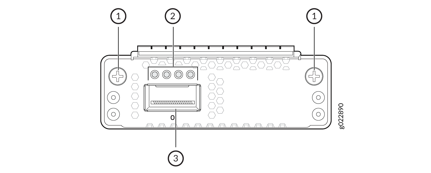
  • 1x100GbE QSFP28 extension module (model number: EX4400-EM-1C): 0.26 lb (0.12 kg)

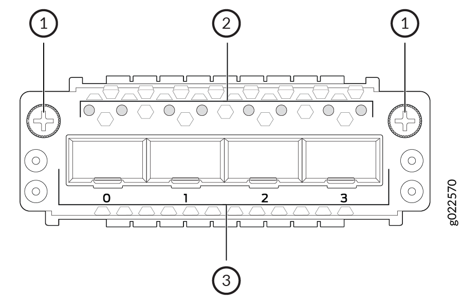
  • 4x10GbE SFP+ extension module (model number: EX4400-EM-4S): 0.2 lb (0.09 kg)

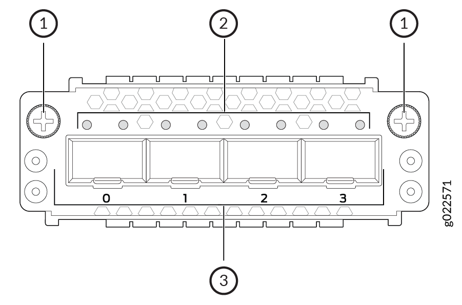
  • 4x25GbE SFP28 extension module (model number: EX4400-EM-4Y): 0.29 lb (0.13 kg)

We ship the switch preinstalled with one power supply, two fan modules, one cover for the empty extension module slot, and one cover for the empty power supply slot.

You can mount an EX4400 switch:

  • On a two-post rack or on two posts of a 19-in. four-post rack by using the two-post mounting brackets provided with the switch.

  • Flush with the front posts of a 19-in. four-post rack by using a separately orderable four-post rack mount kit.

  • In a recessed position inside a 19-in. four-post rack by using the recessed-mounting brackets provided with a separately orderable four-post rack mount kit.

  • On a desk or other level surface by using the rubber feet provided with the switch.

  • On a wall by using a separately orderable wall mount kit.

To know the part numbers for ordering the separately orderable mounting kits, see the EX4400 Switches Datasheet.

Field-Replaceable Units in EX4400 Switches

Field-replaceable units (FRUs) are components that you can replace at your site. The FRUs in EX4400 switches are hot-removable and hot-insertable: You can remove and replace them without powering off the switch or disrupting switch functions. The following are the FRUs in EX4400 switches:

  • Power supplies

  • Fan modules

  • Extension modules

  • Transceivers

Note:

If you have a Juniper J-Care service contract, register any addition, change, or upgrade of hardware components at https://www.juniper.net/customers/support/tools/updateinstallbase/. Failure to do so can result in significant delays if you need replacement parts. This note does not apply if you replace existing components with the same type of component.