EX4400 Models and Specifications
This topic provides details of the EX4400 models and their specifications, information on number of ports and PoE support, throughput, BASE-X and components in the shipment for each model.
The EX4400 line of switches consist of both PoE and non-PoE models and multigigabit port models. These switches run on either AC or DC power and support either back-to-front or front-to-back airflow.
Let's take a look at the different EX4400 models and their specifications.
| Non-PoE Models | PoE Models | Multigigabit Models |
|---|---|---|
| EX4400-24T | EX4400-24P | EX4400-24MP |
| EX4400-24X | EX4400-48P | EX4400-48MP |
| EX4400-48T | EX4400-48XP Switch | EX4400-48MXP Switch |
| EX4400-48F |
EX4400-24P Switch
Components on the Front and Rear Panels of EX4400-24P Switches
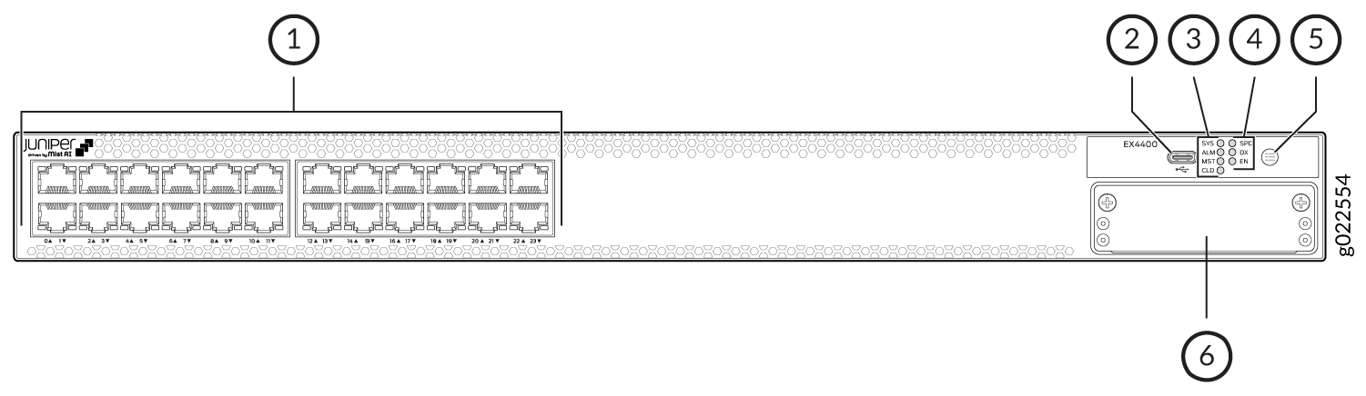
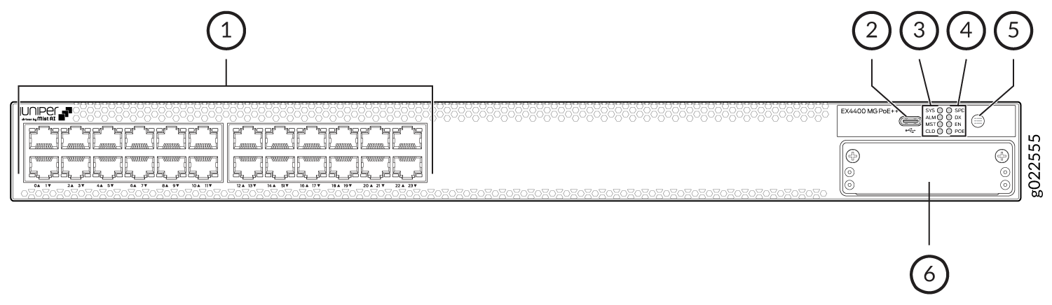
Figure 1 shows the front view of an EX4400-24P switch with 24 RJ-45 ports that support PoE-bt.
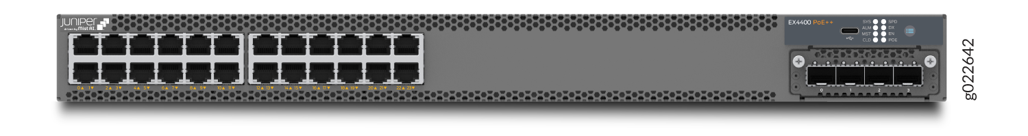
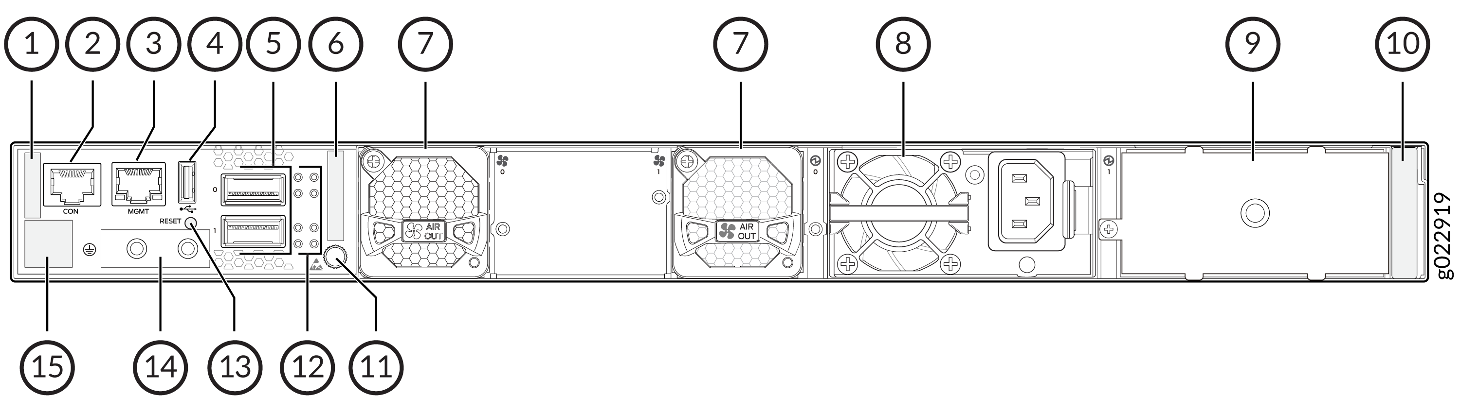
Figure 2 shows the rear view of an EX4400-24T and EX4400-24P switch with AC power supplies.
We enabled the CLD LED feature in Junos OS Release 21.2R1.
Figure 3 shows the components on the front panel of an EX4400-24P switch.

1 — 10/100/1000BASE-T ports. These ports support PoE-bt. | 4 — Port mode LEDs (labeled SPD, DX, EN, and POE) |
2 — USB-C console port | 5 — Factory reset/mode button |
3 — Chassis status LEDs (labeled SYS, ALM, MST, and CLD) | 6 — Extension module slot |
We enabled the CLD LED feature in Junos OS Release 21.2R1.
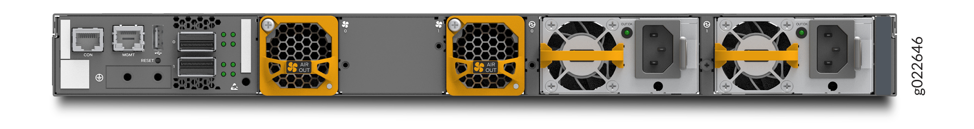
Figure 4 shows the components on the rear panel of an EX4400-24P switch. This model supports 1050-W, 1600-W AC and the 2000-W DC power supplies. The 2000-W DC power supply is separately orderable with the spare switch model - EX4400-24P. The EX4400-24P switch supports 1600-W AC power supply if you have Junos OS Release 22.3R1 or later installed. We ship the switch with one 1050-W power supply. You can order the additional power supply separately. You must not install different models of power supplies in the same chassis.

1 — Serial number ID label | 9 — Empty slot for power supply |
2 — Console port (labeled CON) | 10 — Power supply rating label |
3 — Management port (labeled MGMT) | 11 — ESD point |
4 — USB-A port | 12 — QSFP28 port LEDs |
5 — QSFP28 ports | 13 — Reset button |
6 — CLEI code label | 14 — Protective earthing terminal |
7 — Fan module | 15 — Claim code label |
8 — Power supply |
Table 2 lists the components shipped with EX4400-24P switch models.
Table 3 describes the physical specifications, ports, and throughput of EX4400-24P switches.
Table 4 describes the power supply and cooling system specifications of EX4400-24P switch models
| Model Number | Fan Modules | Power Supply | First Junos OS Release |
|---|---|---|---|
|
EX4400-24P |
Two fan modules with front-to-back airflow (indicated by the AIR OUT label and the orange handle) |
A 1050-W AC power supply with front-to-back airflow (indicated by the AIR OUT label and the orange handle) |
21.1R1 |
|
EX4400-24P-S |
We don't ship fan modules for this model by default; you must order two fan modules separately. |
We don't ship power supplies for this model by default; you must order them separately. |
21.1R1 |
| Item | Description | |
|---|---|---|
| Chassis Dimensions | Height | 1.72 in. (4.37 cm) |
| Width |
17.39 in. (44.17 cm) The outer edges of the front-mounting brackets extend the width to 19 in. (48.2 cm). |
|
| Depth |
15.71 in. (39.9 cm)—With no power supply, fan module, or extension module installed 16.93 in. (43 cm)—With power supply and fan module installed 17.35 in. (44.07 cm)—With power supply, fan module, and extension module installed |
|
| Weight |
We ship the switch preinstalled with one power supply, two fan modules, one cover for the empty extension module slot, and one cover for the empty power supply slot. |
|
| Built-in ports |
100/1000BASE-X ports: 36 100GbE QSFP28 ports: 2 |
|
| PoE Ports (PoE-bt) | 24—delivers upto 90 W per port | |
| Throughput |
324 Gbps—Unidirectional) 648 Gbps—Bbidirectional |
|
| Model | Power Supply Specifications | Cooling System Specifications |
|---|---|---|
| EX4400-24P |
Two power supply slots with one power supply preinstalled 1050 W AC (preinstalled) 1600 W AC (optional) Front-to-back airflow (indicated by the AIR OUT label and the orange handle) |
Two fan module slots with fan modules preinstalled Front-to-back airflow (indicated by the AIR OUT label and the orange handle) |
| EX4400-24P-S |
Two power supply slots 2000 W DC (optional) You need to order power supplies separately and install them in these slots |
Two fan module slots You need to order front-to-back airflow (AFO) fan modules separately and install them in these slots |
EX4400-24T Switches
Components on the Front and Rear Panels of EX4400-24T
Figure 5 shows the front view of an EX4400-24T switch with 24 RJ-45 ports.
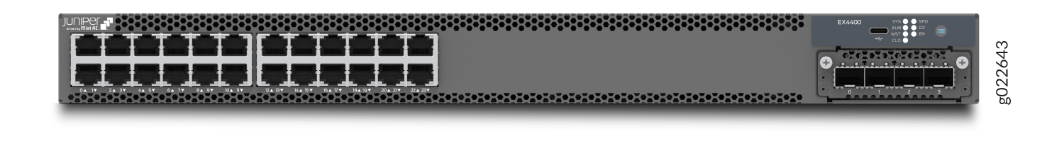
Figure 6 shows the rear view of an EX4400-24T switch with AC power supplies.
Figure 7 shows the rear view of an EX4400-24T switch with DC power supplies.
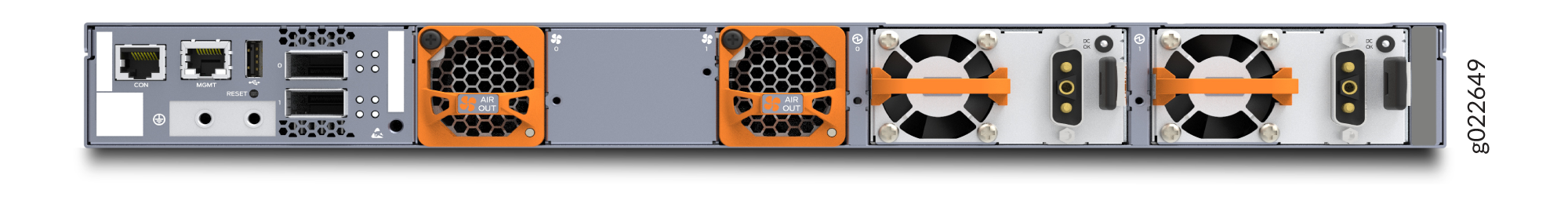
Figure 8 shows the components on the front panel of an EX4400-24T switch.
1 — 10/100/1000BASE-T ports | 4 — Port mode LEDs (labeled SPD, DX, and EN) |
2 — USB-C console port | 5 — Factory reset/mode button |
3 — Chassis status LEDs (labeled SYS, ALM, MST, and CLD) | 6 — Extension module slot |
We enabled the CLD LED feature in Junos OS Release 21.2R1.
EX4400-24T model supports 550-W AC or DC power supplies. You must not install AC and DC power supplies in the same chassis.
Figure 9 shows the components on the rear panel of an EX4400-24T switch with an AC power supply.
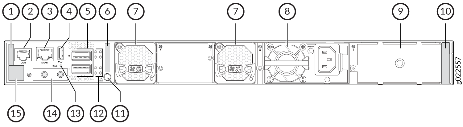
1 — Serial number ID label | 9 — Empty slot for power supply |
2 — Console port (labeled CON) | 10 — Power supply rating label |
3 — Management port (labeled MGMT) | 11 — Electrostatic discharge (ESD) point |
4 — USB-A port | 12 — QSFP28 port LEDs |
5 — QSFP28 ports | 13 — Reset button |
6 — Common Language Equipment Identifier (CLEI) code label | 14 — Protective earthing terminal |
7 — Fan module | 15 — Claim code label |
8 — 550-W AC power supply |
Figure 10 shows the components on the rear panel of an EX4400-24T switch with a DC power supply.
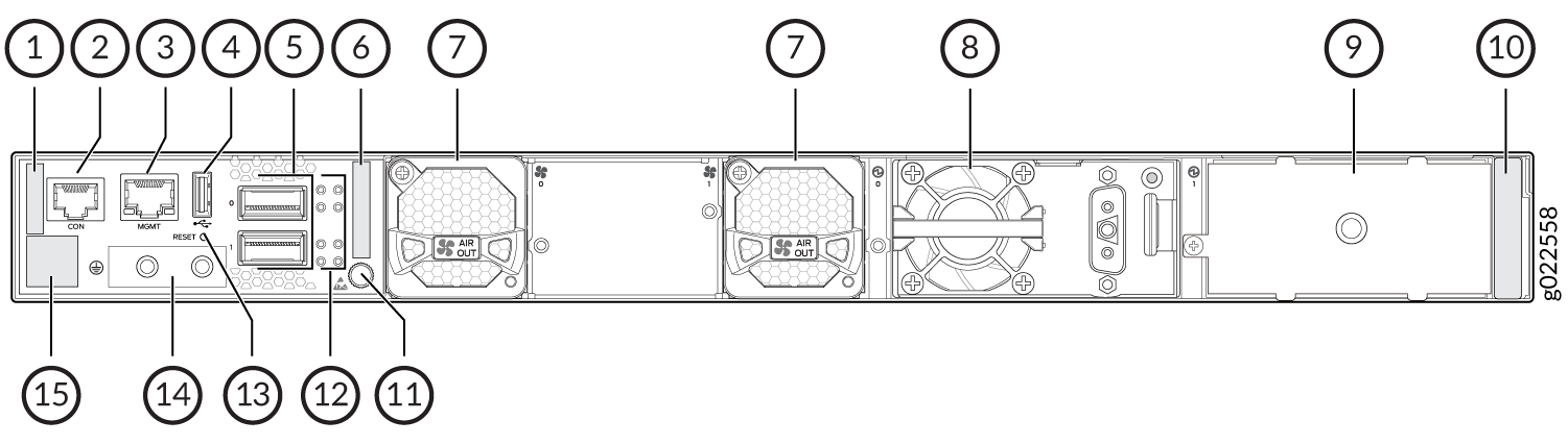
1 — Serial number ID label | 9 — Empty slot for power supply |
2 — Console port (labeled CON) | 10 — Power supply rating label |
3 — Management port (labeled MGMT) | 11 — ESD point |
4 — USB-A port | 12 — QSFP28 port LEDs |
5 — QSFP28 ports | 13 — Reset button |
6 — CLEI code label | 14 — Protective earthing terminal |
7 — Fan module | 15 — Claim code label |
8 — 550-W DC power supply |
Table 5 lists the components shipped with EX4400-24T switch models.
Table 6 describes the physical specifications, ports, and throughput of EX4400-24T switches.
Table 7 describes the power supply and cooling system specifications of EX4400-24T switch models
| Model Number | Fan Modules | Power Supply | First Junos OS Release |
|---|---|---|---|
|
EX4400-24T |
Two fan modules with front-to-back airflow (indicated by the AIR OUT label and the orange handle) |
A 550-W AC power supply with front-to-back airflow (indicated by the AIR OUT label and the orange handle) |
21.1R1 |
|
EX4400-24T-AFI |
Two fan modules with back-to-front airflow (indicated by the AIR IN label and the blue handle) |
A 550-W AC power supply with back-to-front airflow (indicated by the AIR IN label and the blue handle) |
21.1R1 |
|
EX4400-24T-DC |
Two fan modules with front-to-back airflow (indicated by the AIR OUT label and the orange handle) |
A 550-W DC power supply with front-to-back airflow (indicated by the AIR OUT label and the orange handle) |
21.1R1 |
|
EX4400-24T-DC-AFI |
Two fan modules with back-to-front airflow (indicated by the AIR IN label and the blue handle) |
A 550-W DC power supply with back-to-front airflow (indicated by the AIR IN label and the blue handle) |
21.1R1 |
|
EX4400-24T-S |
We don't ship fan modules for this model by default; you must order two fan modules separately. |
We don't ship power supplies for this model by default; you must order them separately. |
21.1R1 |
| Item | Description | |
|---|---|---|
| Chassis Dimensions | Height | 1.72 in. (4.37 cm) |
| Width |
17.39 in. (44.17 cm) The outer edges of the front-mounting brackets extend the width to 19 in. (48.2 cm). |
|
| Depth |
15.71 in. (39.9 cm)—With no power supply, fan module, or extension module installed 16.93 in. (43 cm)—With power supply and fan module installed 17.35 in. (44.07 cm)—With power supply, fan module, and extension module installed |
|
| Weight |
We ship the switch preinstalled with one power supply, two fan modules, one cover for the empty extension module slot, and one cover for the empty power supply slot. |
|
| Built-in ports |
10/100/1000BASE-T ports: 24 100GbE QSFP28 ports: 2 |
|
| Throughput |
324 Gbps—Unidirectional) 648 Gbps—Bbidirectional |
|
| Model | Power Supply Specifications | Cooling System Specifications |
|---|---|---|
| EX4400-24T |
Two power supply slots with one power supply preinstalled 550 W AC Front-to-back airflow (indicated by the AIR OUT label and the orange handle) |
Two fan module slots with fan modules preinstalled Front-to-back airflow (indicated by the AIR OUT label and the orange handle) |
| EX4400-24T-AFI |
Two power supply slots with one power supply preinstalled 550 W AC Back-to-front airflow (indicated by the AIR IN label and the blue handle) |
Two fan module slots with fan modules preinstalled Back-to-front airflow (indicated by the AIR IN label and the blue handle) |
| EX4400-24T-DC |
Two power supply slots with one power supply preinstalled 550 W DC Front-to-back airflow (indicated by the AIR OUT label and the orange handle) |
Two fan module slots with fan modules preinstalled Front-to-back airflow (indicated by the AIR OUT label and the orange handle) |
| EX4400-24T-DC-AFI |
Two power supply slots with one power supply preinstalled 550 W DC Back-to-front airflow (indicated by the AIR IN label and the blue handle) |
Two fan module slots with fan modules preinstalled Back-to-front airflow (indicated by the AIR IN label and the blue handle) |
| EX4400-24T-S |
Two power supply slots You need to order AC or DC power supplies separately and install them in these slots |
Two fan module slots You need to order front-to-back airflow (AFO) or back-to-front airflow (AFI) fan modules separately and install them in these slots |
EX4400-24X Switch
Components on the Front and Rear Panels of EX4400-24X Switches
Figure 11 shows the front view of an EX4400-24X switch with 24 10GbE small form-factor pluggable (SFP)/small form-factor pluggable plus (SFP+) ports.
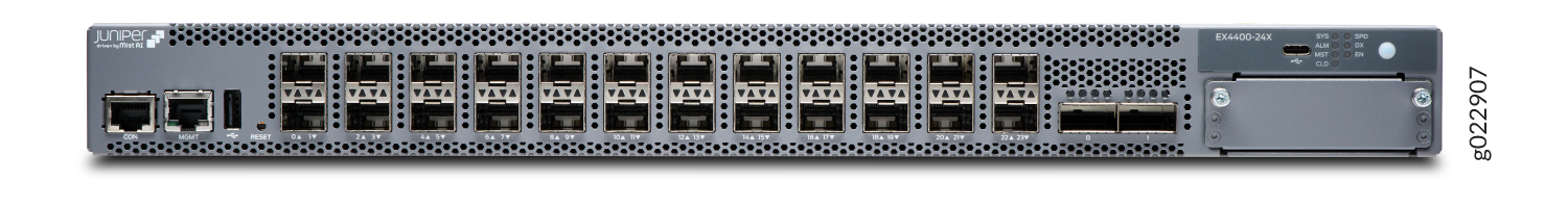
Figure 12 shows the rear view of an EX4400-24X switch with an AC power supply.
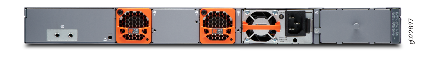
Figure 13 shows the components on the front panel of an EX4400-24X switch.
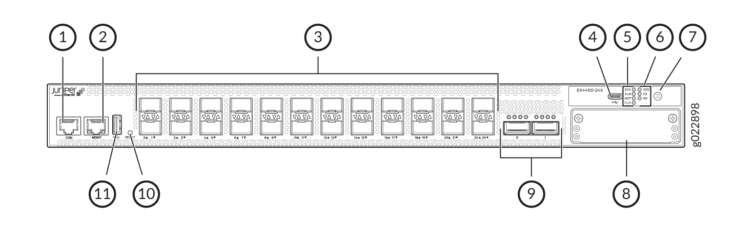
1 — Console port (labeled CON) | 7 — Factory reset/mode button |
2 — Management port (labeled MGMT) | 8 — Extension module slot |
3 — 24 SFP/SFP+ ports | 9 — QSFP28 ports |
4 — USB-C console port | 10 — Reset button |
5 — Chassis status LEDs (labeled SYS, ALM, MST, and CLD) | 11 — USB-A port |
6 — Port mode LEDs (labeled SPD, DX, and EN) |
Figure 14 shows the components on the rear panel of an EX4400-24X switch with an AC power supply.
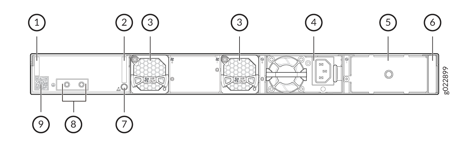
1 — Serial number ID label | 6 — Power supply rating label |
2 — CLEI code label | 7 — ESD point |
3 — Fan module | 8 — Protective earthing terminal |
4 — 550-W AC power supply | 9 — Claim code label |
5 — Empty slot for power supply |
Figure 15 shows the components on the rear panel of an EX4400-24X switch with a DC power supply.
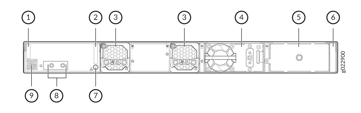
1 — Serial number ID label | 6 — Power supply rating label |
2 — CLEI code label | 7 — ESD point |
3 — Fan module | 8 — Protective earthing terminal |
4 — 550-W DC power supply | 9 — Claim code label |
5 — Empty slot for power supply |
Table 8 lists the components shipped with EX4400-24X switch models.
Table 9 describes the physical specifications, ports, and throughput of EX4400-24X switches.
Table 10 describes the power supply and cooling system specifications of EX4400-24X switch models
| Model Number | Fan Modules | Power Supply | First Junos OS Release |
|---|---|---|---|
|
EX4400-24X |
Two fan modules with front-to-back airflow (indicated by the AIR OUT label and the orange handle) |
A 550-W AC power supply with front-to-back airflow (indicated by the AIR OUT label and the orange handle) |
21.1R1 |
|
EX4400-24X-AFI |
Two fan modules with back-to-front airflow (indicated by the AIR IN label and the blue handle) |
A 550-W AC power supply with back-to-front airflow (indicated by the AIR IN label and the blue handle) |
23.1R1 |
|
EX4400-24X-DC |
Two fan modules with front-to-back airflow (indicated by the AIR OUT label and the orange handle) |
A 550-W DC power supply with front-to-back airflow (indicated by the AIR OUT label and the orange handle) |
23.1R1 |
|
EX4400-24X-DC-AFI |
Two fan modules with back-to-front airflow (indicated by the AIR IN label and the blue handle) |
A 550-W DC power supply with back-to-front airflow (indicated by the AIR IN label and the blue handle) |
23.1R1 |
| Item | Description | |
|---|---|---|
| Chassis Dimensions | Height | 1.72 in. (4.37 cm) |
| Width |
17.39 in. (44.17 cm) The outer edges of the front-mounting brackets extend the width to 19 in. (48.2 cm). |
|
| Depth |
15.71 in. (39.9 cm)—With no power supply, fan module, or extension module installed 16.93 in. (43 cm)—With power supply and fan module installed 17.35 in. (44.07 cm)—With power supply, fan module, and extension module installed |
|
| Weight |
We ship the switch preinstalled with one power supply, two fan modules, one cover for the empty extension module slot, and one cover for the empty power supply slot. |
|
| Built-in ports |
1/10GbE ports: 24 100GbE QSFP28 ports: 2 |
|
| Throughput |
540 Gbps—Unidirectional) 1080 Gbps—Bbidirectional |
|
| Model | Power Supply Specifications | Cooling System Specifications |
|---|---|---|
| EX4400-24X |
Two power supply slots with one power supply preinstalled 550 W AC Front-to-back airflow (indicated by the AIR OUT label and the orange handle) |
Two fan module slots with fan modules preinstalled Front-to-back airflow (indicated by the AIR OUT label and the orange handle) |
| EX4400-24X-AFI |
Two power supply slots with one power supply preinstalled 550 W AC Back-to-front airflow (indicated by the AIR IN label and the blue handle) |
Two fan module slots with fan modules preinstalled Back-to-front airflow (indicated by the AIR IN label and the blue handle) |
| EX4400-24X-DC |
Two power supply slots with one power supply preinstalled 550 W DC Front-to-back airflow (indicated by the AIR OUT label and the orange handle) |
Two fan module slots with fan modules preinstalled Front-to-back airflow (indicated by the AIR OUT label and the orange handle) |
| EX4400-24X-DC-AFI |
Two power supply slots with one power supply preinstalled 550 W DC Back-to-front airflow (indicated by the AIR IN label and the blue handle) |
Two fan module slots with fan modules preinstalled Back-to-front airflow (indicated by the AIR IN label and the blue handle) |
EX4400-48F Switches
Components on the Front and Rear Panels of EX4400-48F Switches
Figure 16 shows the front view of an EX4400-48F switch with 36 SFP ports and 12 SFP+ ports.
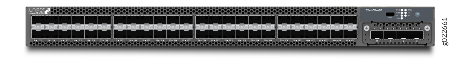
Figure 17 shows the rear view of an EX4400-48F switch with AC power supplies.
Figure 18 shows the rear view of an EX4400-48F switch with DC power supplies.
Figure 19 shows the components on the front panel of an EX4400-48F switch.
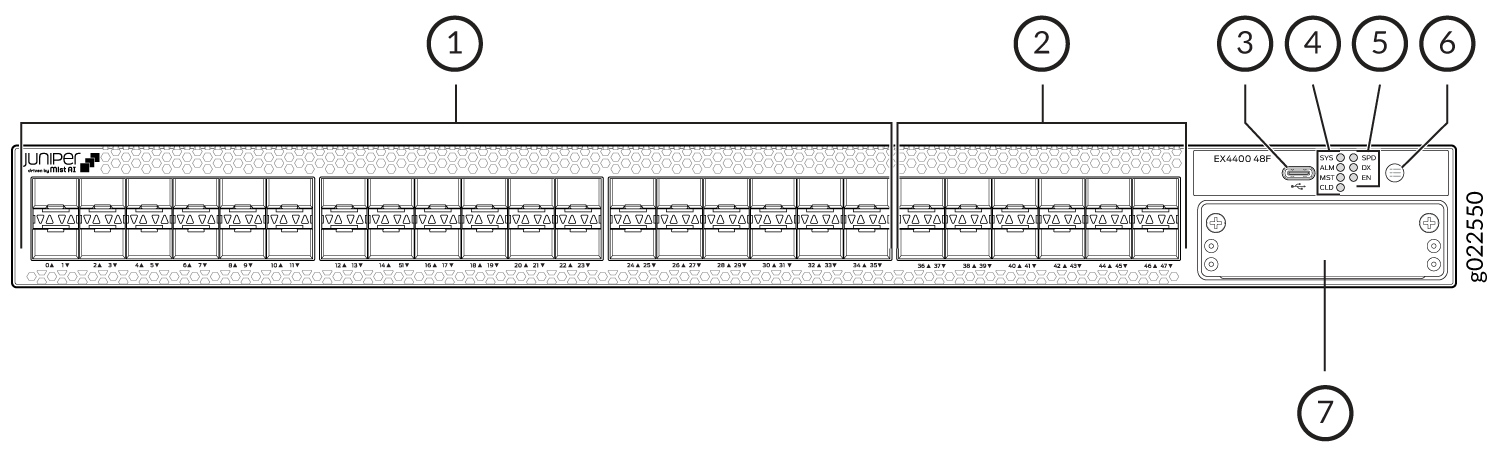
1 — SFP ports | 5 — Port mode LEDs (labeled SPD, DX, and EN) |
2 — SFP+ ports | 6 — Factory reset/mode button |
3 — USB-C console port | 7 — Extension module slot |
4 — Chassis status LEDs (labeled SYS, ALM, MST, and CLD) |
We enabled the CLD LED feature in Junos OS Release 21.2R1.
EX4400-48F model supports 550-W AC or DC power supplies. The EX4400-48F-S switch model supports the 550-W VDC (variable DC) PSU. You must not install a mix of AC,DC, and VDC power supplies in the same chassis.
Figure 20 shows the components on the rear panel of an EX4400-48F switch with an AC power supply.
1 — Serial number ID label | 9 — Empty slot for power supply |
2 — Console port (labeled CON) | 10 — Power supply rating label |
3 — Management port (labeled MGMT) | 11 — ESD point |
4 — USB-A port | 12 — QSFP28 port LEDs |
5 — QSFP28 ports | 13 — Reset button |
6 — CLEI code label | 14 — Protective earthing terminal |
7 — Fan module | 15 — Claim code label |
8 — 550-W AC power supply |
Figure 21 shows the components on the rear panel of an EX4400-48F switch with a DC power supply.
1 — Serial number ID label | 9 — Empty slot for power supply |
2 — Console port (labeled CON) | 10 — Power supply rating label |
3 — Management port (labeled MGMT) | 11 — ESD point |
4 — USB-A port | 12 — QSFP28 port LEDs |
5 — QSFP28 ports | 13 — Reset button |
6 — CLEI code label | 14 — Protective earthing terminal |
7 — Fan module | 15 — Claim code label |
8 — 550-W DC/VDC power supply |
Table 11 lists the components shipped with EX4400-48F switch models.
Table 12 describes the physical specifications, ports, and throughput of EX4400-48F switches.
Table 13 describes the power supply and cooling system specifications of EX4400-48F switch models
| Model Number | Fan Modules | Power Supply | First Junos OS Release |
|---|---|---|---|
|
EX4400-48F |
Two fan modules with front-to-back airflow (indicated by the AIR OUT label and the orange handle) |
A 550-W AC power supply with front-to-back airflow (indicated by the AIR OUT label and the orange handle) |
21.1R1 |
|
EX4400-48F-AFI |
Two fan modules with back-to-front airflow (indicated by the AIR IN label and the blue handle) |
A 550-W AC power supply with back-to-front airflow (indicated by the AIR IN label and the blue handle) |
21.1R1 |
|
EX4400-48F-DC |
Two fan modules with front-to-back airflow (indicated by the AIR OUT label and the orange handle) |
A 550-W DC power supply with front-to-back airflow (indicated by the AIR OUT label and the orange handle) |
21.1R1 |
|
EX4400-48F-DC-AFI |
Two fan modules with back-to-front airflow (indicated by the AIR IN label and the blue handle) |
A 550-W DC power supply with back-to-front airflow (indicated by the AIR IN label and the blue handle) |
21.1R1 |
|
EX4400-48F-S |
We don't ship fan modules for this model by default; you must order two fan modules separately. |
We don't ship power supplies for this model by default; you must order them separately. |
21.1R1 |
| Item | Description | |
|---|---|---|
| Chassis Dimensions | Height | 1.72 in. (4.37 cm) |
| Width |
17.39 in. (44.17 cm) The outer edges of the front-mounting brackets extend the width to 19 in. (48.2 cm). |
|
| Depth |
15.71 in. (39.9 cm)—With no power supply, fan module, or extension module installed 16.93 in. (43 cm)—With power supply and fan module installed 17.35 in. (44.07 cm)—With power supply, fan module, and extension module installed |
|
| Weight |
We ship the switch preinstalled with one power supply, two fan modules, one cover for the empty extension module slot, and one cover for the empty power supply slot. |
|
| Built-in ports |
10/100/1000BASE-X ports: 36 100/1000/2500/5000/10000BASE-X ports: 12 Note:
Following are the port speeds supported when we have fiber transceivers (Base-X) on the ports of EX4400-48F:
In addition these ports can support 1G SFP-T as well. 1G SFP-T speed:
Note: For ports 36-47 these optics
EX-SFP-1FE-[FX/SX/LX] do not support auto negotiation.
|
|
| Throughput |
348 Gbps—Unidirectional) 696 Gbps—Bbidirectional |
|
| Model | Power Supply Specifications | Cooling System Specifications |
|---|---|---|
| EX4400-48F |
Two power supply slots with one power supply preinstalled 550 W AC Front-to-back airflow (indicated by the AIR OUT label and the orange handle) |
Two fan module slots with fan modules preinstalled Front-to-back airflow (indicated by the AIR OUT label and the orange handle) |
| EX4400-48F-AFI |
Two power supply slots with one power supply preinstalled 550 W AC Back-to-front airflow (indicated by the AIR IN label and the blue handle) |
Two fan module slots with fan modules preinstalled Back-to-front airflow (indicated by the AIR IN label and the blue handle) |
| EX4400-48F-DC |
Two power supply slots with one power supply preinstalled 550 W DC Front-to-back airflow (indicated by the AIR OUT label and the orange handle) |
Two fan module slots with fan modules preinstalled Front-to-back airflow (indicated by the AIR OUT label and the orange handle) |
| EX4400-48F-DC-AFI |
Two power supply slots with one power supply preinstalled 550 W DC Back-to-front airflow (indicated by the AIR IN label and the blue handle) |
Two fan module slots with fan modules preinstalled Back-to-front airflow (indicated by the AIR IN label and the blue handle) |
| EX4400-48F-S |
Two power supply slots You need to order AC or DC power supplies separately and install them in these slots |
Two fan module slots You need to order front-to-back airflow (AFO) or back-to-front airflow (AFI) fan modules separately and install them in these slots |
EX4400-48P Switch
Components on the Front and Rear Panels of an EX4400-48P Switch
Figure 22 shows the front view of an EX4400-48P switch with 48 RJ-45 ports that support PoE-bt.
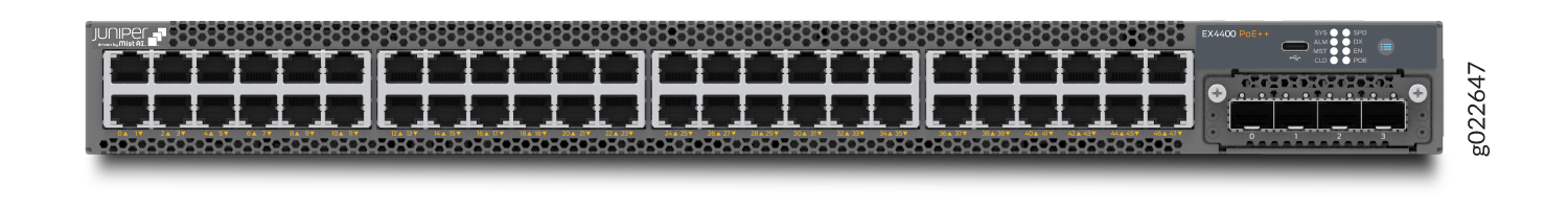
Figure 23 shows the rear view of an EX4400-48P switch.
We’ve enabled the CLD LED feature in Junos OS Release 21.2R1.
Figure 24 shows the components on the front panel of an EX4400-48P switch.

1 — 10/100/1000BASE-T ports. These ports support PoE-bt. | 4 — Port mode LEDs (labeled SPD, DX, EN, and POE) |
2 — USB-C console port | 5 — Factory reset/mode button |
3 — Chassis status LEDs (labeled SYS, ALM, MST, and CLD) | 6 — Extension module slot |
We enabled the CLD LED feature in Junos OS Release 21.2R1.
Figure 25 shows the components on the rear panel of an EX4400-48P switch. This model supports 1600-W AC and 2000-W DC power supplies. The 2000-W DC power supply is separately orderable with the spare switch model - EX4400-48P-S.

1 — Serial number ID label | 9 — Empty slot for power supply |
2 — Console port (labeled CON) | 10 — Power supply rating label |
3 — Management port (labeled MGMT) | 11 — ESD point |
4 — USB-A port | 12 — QSFP28 port LEDs |
5 — QSFP28 ports | 13 — Reset button |
6 — CLEI code label | 14 — Protective earthing terminal |
7 — Fan module | 15 — Claim code label |
8 — Power supply |
Table 14 lists the components shipped with EX4400-48P switch models.
Table 15 describes the physical specifications, ports, and throughput of EX4400-48P switches.
Table 16 describes the power supply and cooling system specifications of EX4400-48P switch models
| Model Number | Fan Modules | Power Supply | First Junos OS Release |
|---|---|---|---|
|
EX4400-48P |
Two fan modules with front-to-back airflow (indicated by the AIR OUT label and the orange handle) |
A 1600-W AC power supply with front-to-back airflow (indicated by the AIR OUT label and the orange handle). |
21.1R1 |
|
EX4400-48P-S |
We don't ship fan modules for this model by default; you must order two fan modules separately. |
We don't ship power supplies for this model by default; you must order them separately. |
21.1R1 |
| Item | Description | |
|---|---|---|
| Chassis Dimensions | Height | 1.72 in. (4.37 cm) |
| Width |
17.39 in. (44.17 cm) The outer edges of the front-mounting brackets extend the width to 19 in. (48.2 cm). |
|
| Depth |
15.71 in. (39.9 cm)—With no power supply, fan module, or extension module installed 16.93 in. (43 cm)—With power supply and fan module installed 17.35 in. (44.07 cm)—With power supply, fan module, and extension module installed |
|
| Weight |
We ship the switch preinstalled with one power supply, two fan modules, one cover for the empty extension module slot, and one cover for the empty power supply slot. |
|
| Built-in ports |
10-Mbps/100-Mbps/1000-Mbps PoE ports: 48 100GbE QSFP28 ports: 2 |
|
| PoE Ports (PoE-bt) | 48—delivers upto 90 W per port | |
| Throughput |
324 Gbps—Unidirectional) 648 Gbps—Bbidirectional |
|
| Model | Power Supply Specifications | Cooling System Specifications |
|---|---|---|
| EX4400-48P |
Two power supply slots with one power supply preinstalled 1600 W AC (optional) Front-to-back airflow (indicated by the AIR OUT label and the orange handle) |
Two fan module slots with fan modules preinstalled Front-to-back airflow (indicated by the AIR OUT label and the orange handle) |
| EX4400-48P-S |
Two power supply slots 2000 DC (optional) You need to order power supplies separately and install them in these slots |
Two fan module slots You need to order front-to-back airflow (AFO) fan modules separately and install them in these slots |
EX4400-48XP Switch
Components on the Front and Rear Panels of an EX4400-48XP Switch
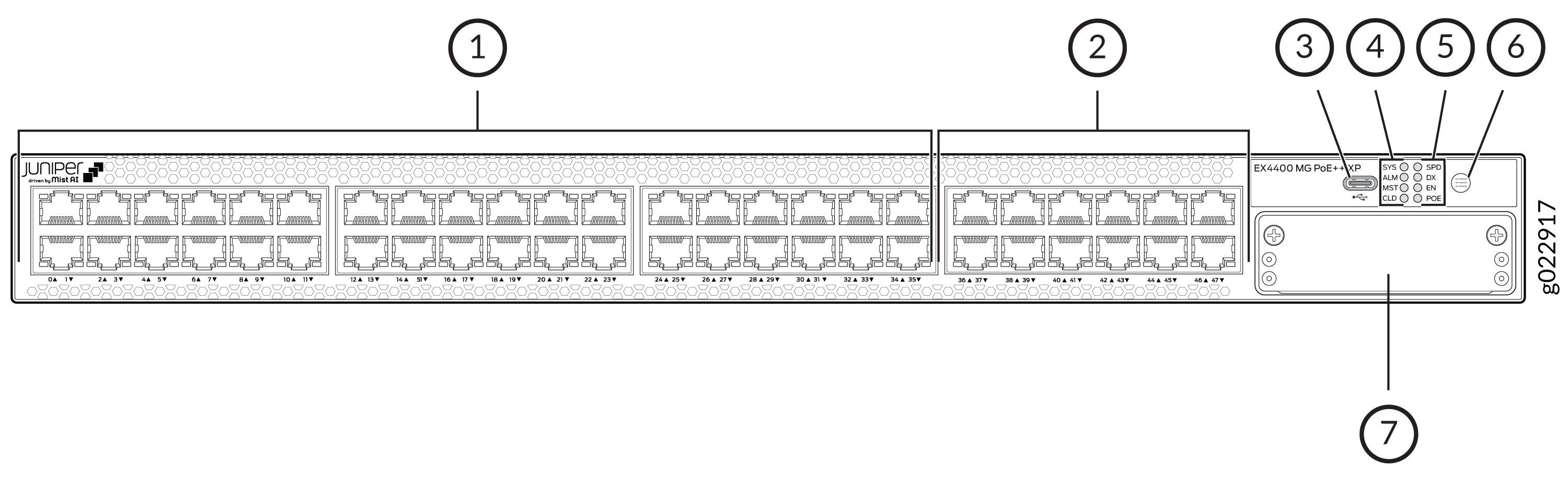
The following figure shows the components on the front panel of an EX4400-48XP switch.
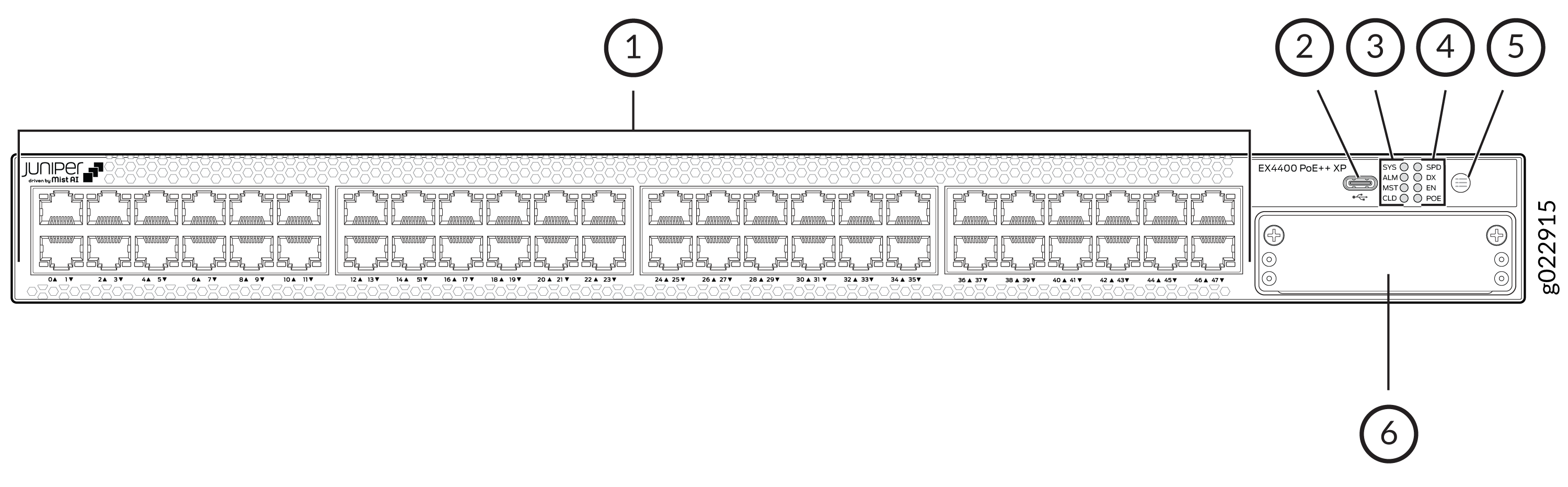
1 — 10/100/1000BASE-T ports. These ports support PoE-bt. | 4 — Port mode LEDs (labeled SPD, DX, EN, and POE) |
2 — USB-C console port | 5 — Factory reset/mode button |
3 — Chassis status LEDs (labeled SYS, ALM, MST, and CLD) | 6 — Extension module slot |
We enabled the CLD LED feature in Junos OS Release 21.2R1.
The following figure shows the components on the rear panel of an EX4400-48XP switch with AC power supply. This model supports the 2000-W AC and the 2000-W DC power supply. The 2000-W DC power supply is separately orderable with the spare switch model - EX4400-48XP-S.
1 — Serial number ID label | 9 — Empty slot for power supply |
2 — Console port (labeled CON) | 10 — Power supply rating label |
3 — Management port (labeled MGMT) | 11 — ESD point |
4 — USB-A port | 12 — QSFP28 port LEDs |
5 — QSFP28 ports | 13 — Reset button |
6 — CLEI code label | 14 — Protective earthing terminal |
7 — Fan module | 15 — Claim code label |
8 — Power supply |
| Model Number | Fan Modules | Power Supply | First Junos OS Release |
|---|---|---|---|
|
EX4400-48XP |
Two fan modules with front-to-back airflow (indicated by the AIR OUT label and the orange handle) |
A 2000-W AC power supply with front-to-back airflow (indicated by the AIR OUT label and the orange handle) |
24.2R1-S1 |
|
EX4400-48XP-S |
We don't ship fan modules for this model by default; you must order two fan modules separately. |
We don't ship power supplies for this model by default; you must order them separately. |
24.2R1-S1 |
| Item | Description | |
|---|---|---|
| Chassis Dimensions | Height | 1.72 in. (4.37 cm) |
| Width |
17.39 in. (44.17 cm) The outer edges of the front-mounting brackets extend the width to 19 in. (48.2 cm). |
|
| Depth |
15.71 in. (39.9 cm)—With no power supply, fan module, or extension module installed 16.93 in. (43 cm)—With power supply and fan module installed 17.35 in. (44.07 cm)—With power supply, fan module, and extension module installed |
|
| Weight |
We ship the switch preinstalled with one power supply, two fan modules, one cover for the empty extension module slot, and one cover for the empty power supply slot. |
|
| Built-in ports |
10-Mbps/100-Mbps/1000-Mbps PoE ports: 48 100GbE QSFP28 ports: 2 |
|
| PoE Ports (PoE-bt) |
48—delivers maximum value of 90W per port and an average of 75W per port when all 48 ports are loaded simultaneously using dual PSU at high voltage line. |
|
| Throughput |
324 Gbps—Unidirectional) 648 Gbps—Bbidirectional |
|
| Model | Power Supply Specifications | Cooling System Specifications |
|---|---|---|
| EX4400-48XP |
Two power supply slots with one power supply preinstalled 2000 W AC Front-to-back airflow (indicated by the AIR OUT label and the orange handle) |
Two fan module slots with fan modules preinstalled Front-to-back airflow (indicated by the AIR OUT label and the orange handle) |
|
EX4400-48XP-S |
Two power supply slots 2000 W DC (optional) You need to order power supplies separately and install them in these slots |
Two fan module slots You need to order front-to-back airflow (AFO) fan modules separately and install them in these slots |
EX4400-48T Switches
Components on the Front and Rear Panels of EX4400-48T and EX4400-48P Switches
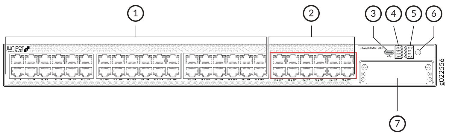
Figure 28 shows the front view of an EX4400-48T switch with 48 RJ-45 ports.
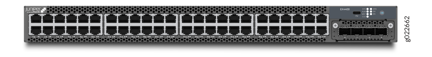
Figure 29 shows the rear view of an EX4400-48T switch with AC power supplies.
Figure 30 shows the rear view of an EX4400-48T switch with DC power supplies.
Figure 31 shows the components on the front panel of an EX4400-48T switch.
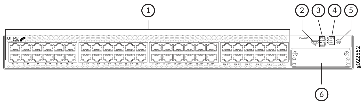
1 — 10/100/1000BASE-T ports | 4 — Port mode LEDs (labeled SPD, DX, and EN) |
2 — USB-C console port | 5 — Factory reset/mode button |
3 — Chassis status LEDs (labeled SYS, ALM, MST, and CLD) | 6 — Extension module slot |
We enabled the CLD LED feature in Junos OS Release 21.2R1.
EX4400-48T model supports 550-W AC or DC power supplies. You must not install AC and DC power supplies in the same chassis.
Figure 32 shows the components on the rear panel of an EX4400-48T switch with an AC power supply.
1 — Serial number ID label | 9 — Empty slot for power supply |
2 — Console port (labeled CON) | 10 — Power supply rating label |
3 — Management port (labeled MGMT) | 11 — ESD point |
4 — USB-A port | 12 — QSFP28 port LEDs |
5 — QSFP28 ports | 13 — Reset button |
6 — CLEI code label | 14 — Protective earthing terminal |
7 — Fan module | 15 — Claim code label |
8 — 550-W AC power supply |
Figure 33 shows the components on the rear panel of an EX4400-48T switch with a DC power supply.
1 — Serial number ID label | 9 — Empty slot for power supply |
2 — Console port (labeled CON) | 10 — Power supply rating label |
3 — Management port (labeled MGMT) | 11 — ESD point |
4 — USB-A port | 12 — QSFP28 port LEDs |
5 — QSFP28 ports | 13 — Reset button |
6 — CLEI code label | 14 — Protective earthing terminal |
7 — Fan module | 15 — Claim code label |
8 — 550-W DC power supply |
Table 20 lists the components shipped with EX4400-48T switch models.
Table 21 describes the physical specifications, ports, and throughput of EX4400-48T switches.
Table 22 describes the power supply and cooling system specifications of EX4400-48T switch models
| Model Number | Fan Modules | Power Supply | First Junos OS Release |
|---|---|---|---|
|
EX4400-48T |
Two fan modules with front-to-back airflow (indicated by the AIR OUT label and the orange handle) |
A 550-W AC power supply with front-to-back airflow (indicated by the AIR OUT label and the orange handle) |
21.1R1 |
|
EX4400-48T-AFI |
Two fan modules with back-to-front airflow (indicated by the AIR IN label and the blue handle) |
A 550-W AC power supply with back-to-front airflow (indicated by the AIR IN label and the blue handle) |
21.1R1 |
|
EX4400-48T-DC |
Two fan modules with front-to-back airflow (indicated by the AIR OUT label and the orange handle) |
A 550-W DC power supply with front-to-back airflow (indicated by the AIR OUT label and the orange handle) |
21.1R1 |
|
EX4400-48T-DC-AFI |
Two fan modules with back-to-front airflow (indicated by the AIR IN label and the blue handle) |
A 550-W DC power supply with back-to-front airflow (indicated by the AIR IN label and the blue handle) |
21.1R1 |
|
EX4400-48T-S |
We don't ship fan modules for this model by default; you must order two fan modules separately. |
We don't ship power supplies for this model by default; you must order them separately. |
21.1R1 |
| Item | Description | |
|---|---|---|
| Chassis Dimensions | Height | 1.72 in. (4.37 cm) |
| Width |
17.39 in. (44.17 cm) The outer edges of the front-mounting brackets extend the width to 19 in. (48.2 cm). |
|
| Depth |
15.71 in. (39.9 cm)—With no power supply, fan module, or extension module installed 16.93 in. (43 cm)—With power supply and fan module installed 17.35 in. (44.07 cm)—With power supply, fan module, and extension module installed |
|
| Weight |
We ship the switch preinstalled with one power supply, two fan modules, one cover for the empty extension module slot, and one cover for the empty power supply slot. |
|
| Built-in ports |
10/100/1000BASE-T ports: 48 100GbE QSFP28 ports: 2 |
|
| Throughput |
348 Gbps—Unidirectional) 696 Gbps—Bbidirectional |
|
| Model | Power Supply Specifications | Cooling System Specifications |
|---|---|---|
| EX4400-48T |
Two power supply slots with one power supply preinstalled 550 W AC Front-to-back airflow (indicated by the AIR OUT label and the orange handle) |
Two fan module slots with fan modules preinstalled Front-to-back airflow (indicated by the AIR OUT label and the orange handle) |
| EX4400-48T-AFI |
Two power supply slots with one power supply preinstalled 550 W AC Back-to-front airflow (indicated by the AIR IN label and the blue handle) |
Two fan module slots with fan modules preinstalled Back-to-front airflow (indicated by the AIR IN label and the blue handle) |
| EX4400-48T-DC |
Two power supply slots with one power supply preinstalled 550 W DC Front-to-back airflow (indicated by the AIR OUT label and the orange handle) |
Two fan module slots with fan modules preinstalled Front-to-back airflow (indicated by the AIR OUT label and the orange handle) |
| EX4400-48T-DC-AFI |
Two power supply slots with one power supply preinstalled 550 W DC Back-to-front airflow (indicated by the AIR IN label and the blue handle) |
Two fan module slots with fan modules preinstalled Back-to-front airflow (indicated by the AIR IN label and the blue handle) |
| EX4400-48T-S |
Two power supply slots You need to order AC or DC power supplies separately and install them in these slots |
Two fan module slots You need to order front-to-back airflow (AFO) or back-to-front airflow (AFI) fan modules separately and install them in these slots |
EX4400-24MP Switch
Components on the Front and Rear Panels of EX4400-24MP Switches
Figure 34 shows the front view of an EX4400-24MP switch with 24 RJ-45 ports that support PoE-bt.
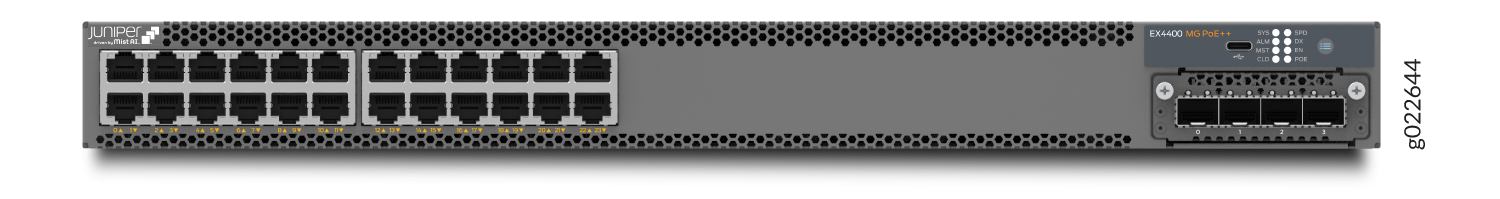
Figure 35 shows the rear view of an EX4400-24MP switch.
Figure 36 shows the components on the front panel of an EX4400-24MP switch.
1 — 100-Mbps/1-Gbps/2.5-Gbps/5-Gbps/10-Gbps RJ-45 ports. These ports support PoE-bt. | 4 — Port mode LEDs (labeled SPD, DX, EN, and POE) |
2 — USB-C console port | 5 — Factory reset/mode button |
3 — Chassis status LEDs (labeled SYS, ALM, MST, and CLD) | 6 — Extension module slot |
Figure 37 shows the components on the rear panel of an EX4400-24MP switch. We ship the switch with one 1050-W power supply by default. You can order an additional power supply separately. The model also supports the 2000-W DC PSU, which you can order separately with the spare switch model- EX4400-24MP-S.
If you have Junos OS Release 22.3R1 or later installed, the switch supports the 1600-W AC power supply.
You must install only one model of power supply in a chassis. Do not mix different models.
1 — Serial number ID label | 9 — Empty slot for power supply |
2 — Console port (labeled CON) | 10 — Power supply rating label |
3 — Management port (labeled MGMT) | 11 — ESD point |
4 — USB-A port | 12 — QSFP28 port LEDs |
5 — QSFP28 ports | 13 — Reset button |
6 — CLEI code label | 14 — Protective earthing terminal |
7 — Fan module | 15 — Claim code label |
8 — Power supply |
Table 23 lists the components shipped with EX4400-24MP switch models.
Table 24 describes the physical specifications, ports, and throughput of EX4400-24MP switches.
Table 25 describes the power supply and cooling system specifications of EX4400-24MP switch models
| Model Number | Fan Modules | Power Supply | First Junos OS Release |
|---|---|---|---|
|
EX4400-24MP |
Two fan modules with front-to-back airflow (indicated by the AIR OUT label and the orange handle) |
A 1050-W AC power supply with front-to-back airflow (indicated by the AIR OUT label and the orange handle) |
21.1R1 |
|
EX4400-24MP-S |
We don't ship fan modules for this model by default; you must order two fan modules separately. |
We don't ship power supplies for this model by default; you must order them separately. |
21.1R1 |
| Item | Description | |
|---|---|---|
| Chassis Dimensions | Height | 1.72 in. (4.37 cm) |
| Width |
17.39 in. (44.17 cm) The outer edges of the front-mounting brackets extend the width to 19 in. (48.2 cm). |
|
| Depth |
15.71 in. (39.9 cm)—With no power supply, fan module, or extension module installed 16.93 in. (43 cm)—With power supply and fan module installed 17.35 in. (44.07 cm)—With power supply, fan module, and extension module installed |
|
| Weight |
We ship the switch preinstalled with one power supply, two fan modules, one cover for the empty extension module slot, and one cover for the empty power supply slot. |
|
| Built-in ports |
100-Mbps/1-Gbps/2.5-Gbps/5-Gbps/10-Gbps ports: 24 |
|
| PoE Ports (PoE-bt) | 24—delivers upto 90 W per port | |
| Throughput |
540 Gbps—Unidirectional) 1080 Gbps—Bbidirectional |
|
| Model | Power Supply Specifications | Cooling System Specifications |
|---|---|---|
| EX4400-24MP |
Two power supply slots with one power supply preinstalled 1050 W AC (preinstalled) 1600 W AC (optional) Front-to-back airflow (indicated by the AIR OUT label and the orange handle) |
Two fan module slots with fan modules preinstalled Front-to-back airflow (indicated by the AIR OUT label and the orange handle) |
| EX4400-24MP-S |
Two power supply slots 2000 W DC (optional) You need to order power supplies separately and install them in these slots |
Two fan module slots You need to order front-to-back airflow (AFO) fan modules separately and install them in these slots |
EX4400-48MP Switch
Components on the Front and Rear Panels of EX4400-48MP Switches
Figure 38 shows the front view of an EX4400-48MP switch with 48 RJ-45 ports that support PoE-bt.
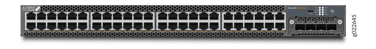
Figure 39 shows the rear view of an EX4400-48MP switch.
Figure 40 shows the components on the front panel of an EX4400-48MP switch.
1 — 100-Mbps/1-Gbps/2.5-Gbps RJ-45 ports. These ports support PoE-bt. | 5 — Port mode LEDs (labeled SPD, DX, EN, and POE) |
2 — 100-Mbps/1-Gbps/2.5-Gbps/5-Gbps/10-Gbps RJ-45 ports. These ports support PoE-bt. | 6 — Factory reset/mode button |
3 — USB-C console port | 7 — Extension module slot |
4 — Chassis status LEDs (labeled SYS, ALM, MST, and CLD) |
Figure 41 shows the components on the rear panel of an EX4400-48MP switch. This model supports the 1600-W AC power supply and the 2000-W DC power supply. The 2000-W DC power supply is separately orderable with the spare switch model - EX4400-48MP-S.
1 — Serial number ID label | 9 — Empty slot for power supply |
2 — Console port (labeled CON) | 10 — Power supply rating label |
3 — Management port (labeled MGMT) | 11 — ESD point |
4 — USB-A port | 12 — QSFP28 port LEDs |
5 — QSFP28 ports | 13 — Reset button |
6 — CLEI code label | 14 — Protective earthing terminal |
7 — Fan module | 15 — Claim code label |
8 — Power supply |
Table 26 lists the components shipped with EX4400-48MP switch models.
Table 27 describes the physical specifications, ports, and throughput of EX4400-48MP switches.
Table 28 describes the power supply and cooling system specifications of EX4400-48MP switch models
| Model Number | Fan Modules | Power Supply | First Junos OS Release |
|---|---|---|---|
|
EX4400-48MP |
Two fan modules with front-to-back airflow (indicated by the AIR OUT label and the orange handle) |
A 1600-W AC power supply with front-to-back airflow (indicated by the AIR OUT label and the orange handle) |
21.1R1 |
|
EX4400-48MP-S |
We don't ship fan modules for this model by default; you must order two fan modules separately. |
We don't ship power supplies for this model by default; you must order them separately. |
21.1R1 |
| Item | Description | |
|---|---|---|
| Chassis Dimensions | Height | 1.72 in. (4.37 cm) |
| Width |
17.39 in. (44.17 cm) The outer edges of the front-mounting brackets extend the width to 19 in. (48.2 cm). |
|
| Depth |
15.71 in. (39.9 cm)—With no power supply, fan module, or extension module installed 16.93 in. (43 cm)—With power supply and fan module installed 17.35 in. (44.07 cm)—With power supply, fan module, and extension module installed |
|
| Weight |
We ship the switch preinstalled with one power supply, two fan modules, one cover for the empty extension module slot, and one cover for the empty power supply slot. |
|
| Built-in ports |
100-Mbps/1-Gbps/2.5-Gbps/5-Gbps/10-Gbps PoE ports: 12 100-Mbps/1-Gbps/2.5-Gbps PoE ports: 36 |
|
| PoE Ports (PoE-bt) | 48—delivers upto 90 W per port | |
| Throughput |
510 Gbps—Unidirectional) 1020 Gbps—Bidirectional |
|
| Model | Power Supply Specifications | Cooling System Specifications |
|---|---|---|
| EX4400-48MP |
Two power supply slots with one power supply preinstalled 1600 W AC (optional) Front-to-back airflow (indicated by the AIR OUT label and the orange handle) |
Two fan module slots with fan modules preinstalled Front-to-back airflow (indicated by the AIR OUT label and the orange handle) |
| EX4400-48MP-S |
Two power supply slots 2000 W DC (optional) You need to order power supplies separately and install them in these slots |
Two fan module slots You need to order front-to-back airflow (AFO) fan modules separately and install them in these slots |
EX4400-48MXP Switch
Components on the Front and Rear Panels of EX4400-48MXP Switches
The following figure shows the components on the front panel of an EX4400-48MXP switch.
1 — 100-Mbps/1-Gbps/2.5-Gbps RJ-45 ports. These ports support PoE-bt. | 5 — Port mode LEDs (labeled SPD, DX, EN, and POE) |
2 — 100-Mbps/1-Gbps/2.5-Gbps/5-Gbps/10-Gbps RJ-45 ports. These ports support PoE-bt. | 6 — Factory reset/mode button |
3 — USB-C console port | 7 — Extension module slot |
4 — Chassis status LEDs (labeled SYS, ALM, MST, and CLD) |
The following figure shows the components on the rear panel of an EX4400-48MXP switch. This model supports 2000-W AC and 2000-W DC power supplies. The 2000-W DC power supply is separately orderable with the spare switch model - EX4400-48MXP-S.
1 — Serial number ID label | 9 — Empty slot for power supply |
2 — Console port (labeled CON) | 10 — Power supply rating label |
3 — Management port (labeled MGMT) | 11 — ESD point |
4 — USB-A port | 12 — QSFP28 port LEDs |
5 — QSFP28 ports | 13 — Reset button |
6 — CLEI code label | 14 — Protective earthing terminal |
7 — Fan module | 15 — Claim code label |
8 — Power supply |
| Model Number | Fan Modules | Power Supply | First Junos OS Release |
|---|---|---|---|
|
EX4400-48MXP |
Two fan modules with front-to-back airflow (indicated by the AIR OUT label and the orange handle) |
A 2000-W AC power supply with front-to-back airflow (indicated by the AIR OUT label and the orange handle) |
24.2R1-S1 |
|
EX4400-48MXP-S |
We don't ship fan modules for this model by default; you must order two fan modules separately. |
We don't ship power supplies for this model by default; you must order them separately. |
24.2R1-S1 |
| Item | Description | |
|---|---|---|
| Chassis Dimensions | Height | 1.72 in. (4.37 cm) |
| Width |
17.39 in. (44.17 cm) The outer edges of the front-mounting brackets extend the width to 19 in. (48.2 cm). |
|
| Depth |
15.71 in. (39.9 cm)—With no power supply, fan module, or extension module installed 16.93 in. (43 cm)—With power supply and fan module installed 17.35 in. (44.07 cm)—With power supply, fan module, and extension module installed |
|
| Weight |
We ship the switch preinstalled with one power supply, two fan modules, one cover for the empty extension module slot, and one cover for the empty power supply slot. |
|
| Built-in ports |
100-Mbps/1-Gbps/2.5-Gbps/5-Gbps/10-Gbps PoE ports: 12 100-Mbps/1-Gbps/2.5-Gbps PoE ports: 36 100GbE QSFP28 ports: 2 |
|
| PoE Ports (PoE-bt) |
48—delivers up to maximum value of 90W per port and an average of 75W per port when all 48 ports are loaded simultaneously using dual PSU at high voltage line. |
|
| Throughput |
510 Gbps—Unidirectional) 1020 Gbps—Bidirectional |
|
| Model | Power Supply Specifications | Cooling System Specifications |
|---|---|---|
| EX4400-48MXP |
Two power supply slots with one power supply preinstalled 2000 W AC Front-to-back airflow (indicated by the AIR OUT label and the orange handle) |
Two fan module slots with fan modules preinstalled Front-to-back airflow (indicated by the AIR OUT label and the orange handle) |
| EX4400-48MXP-S |
Two power supply slots 2000 W DC (optional) You need to order power supplies separately and install them in these slots |
Two fan module slots You need to order front-to-back airflow (AFO) fan modules separately and install them in these slots |
EX4400 could be stuck during reboot, if one end of a twisted pair cable is connected to primary console port (RJ45) and the other end is left dangling/unconnected. This is noticed with twisted pair cables of length 15ft and above only. And no issues noticed when the box is up and running even if there is a dangling twisted pair cable. So, it is not recommended to use twisted pair cable of length 15 ft and above. And if it is unavoidable to use twisted pair cable of length 15 ft and above, atleast ensure that both ends of the the cable are connected or both ends disconnected. Connecting one end of such a cable to the switch and leaving the other end dangling can cause this issue during reboot.