EX4400 Chassis
Chassis Physical Specifications for EX4400 Switches
The EX4400 switch chassis is a rigid sheet-metal structure that houses all components of the switch. Table 1 summarizes the physical specifications of the EX4400 switch chassis.
|
Description |
Value |
|---|---|
|
Chassis height |
1.72 in. (4.37 cm) |
|
Chassis width |
17.39 in. (44.17 cm) The outer edges of the front-mounting brackets extend the width to 19 in. (48.2 cm). |
|
Chassis depth |
|
|
Weight |
We ship the switch preinstalled with one power supply, two fan modules, one cover for the empty extension module slot, and one cover for the empty power supply slot. |
|
Description |
Value |
|---|---|
|
Width |
1.65 in (4.18 cm) |
|
Height |
1.65 in (4.18 cm) |
|
Depth |
4.55 in (11.57 cm) |
|
Description |
Value |
|---|---|
|
Width |
3.27 in (8.3 cm) |
|
Height |
1.59 in (4.04 cm) |
|
Depth |
8.88 in (22.56 cm) 550-W VDC PSU - 9.48 in (24 cm) |
You can mount an EX4400 switch:
-
On a two-post rack or on two posts of a 19-in. four-post rack by using the two-post mounting brackets provided with the switch.
-
Flush with the front posts of a 19-in. four-post rack by using a separately orderable four-post rack mount kit.
-
In a recessed position inside a 19-in. four-post rack by using the recessed-mounting brackets provided with a separately orderable four-post rack mount kit.
-
On a desk or other level surface by using the rubber feet provided with the switch.
-
On a wall by using a separately orderable wall mount kit.
To know the part numbers for ordering the separately orderable mounting kits, see the EX4400 Switches Datasheet.
See EX4400 Models and Specifications to know more about the EX4400 models and their specifications.
Chassis Status LEDs on EX4400 Switches
Each EX4400 switch has four chassis status LEDs (labeled SYS, ALM, MST, and CLD) on the right-hand side of the front panel (see Figure 1).
For information on the blink patterns of the CLD LED, which provide the cloud connection status of the switch, see Cloud-Ready LED Blink Patterns, or see Cloud-Ready Connection Process, to understand how the cloud connection works.
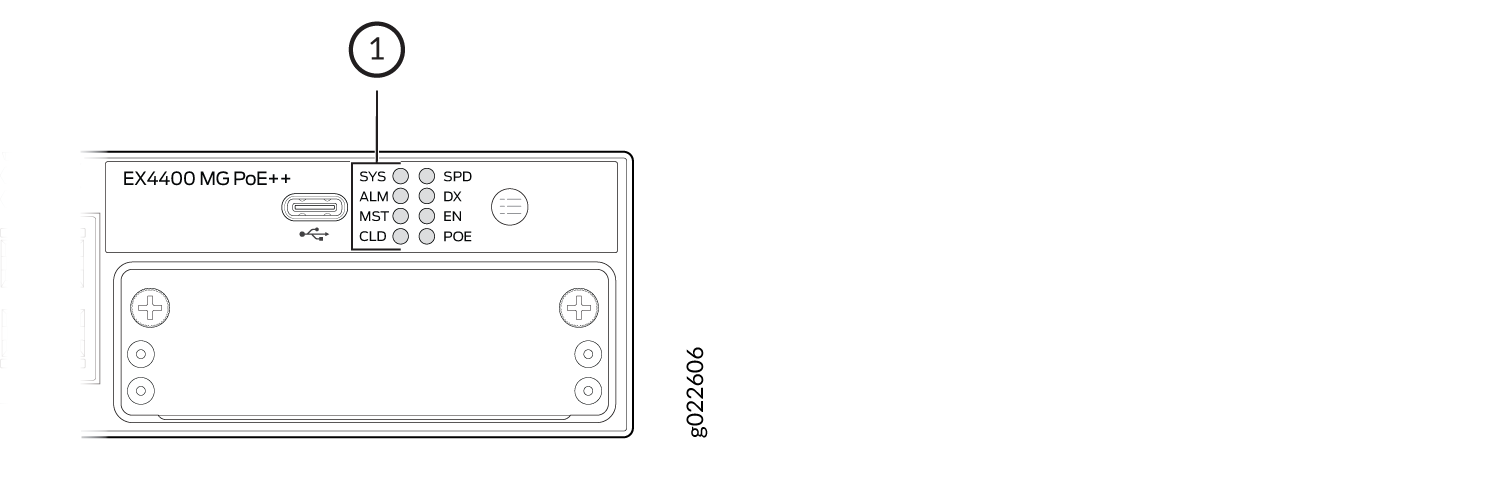
1 — Chassis status LEDs |
Table 4
describes the chassis status LEDs labeled SYS,
ALM, and MST on an EX4400 switch,
their colors and states, and the status they indicate. You can view the colors of
the LEDs remotely through the CLI by issuing the show chassis led
operational mode command. All LEDs can be lit simultaneously.
|
LED Label |
Color |
State and Description |
|---|---|---|
|
SYS |
Green |
|
|
Unlit |
The switch is powered off or is halted. |
|
|
ALM |
Red |
There is a major hardware fault, such as a temperature alarm or a power failure alarm, and the switch is halted. A major alarm indicates a critical error condition that requires immediate attention (see Chassis Component Alarm Conditions on EX4400 Switches). |
|
Amber |
There is a minor alarm, such as a software or a hardware error. Power off the switch and then power it on. Monitor the switch to see whether it is working properly. A minor alarm indicates a noncritical condition that requires monitoring or maintenance. A minor alarm that is left unchecked might cause interruption in service or performance degradation. |
|
|
Unlit |
There is no alarm or the switch is halted. |
|
|
MST |
Green |
In a standalone switch:
|
|
In a Virtual Chassis configuration:
|
Issuing request system power-off doesn't power-off the
SYS LED, which continues to blink. It is because this
command will power-off only the CPU board. As CPU board asserts platform reset
during shutdown process, it will trigger SYS LED to enter
default state of blinking. This is expected behavior.
In a VC involving EX4400-48XP or EX4400-48MXP, if request system
power-off member member number of the EX4400-48XP or
EX4400-48MXP
is issued to power-off the FPC; all of
its LEDs become unlit as expected but the SYS LED
continues to blink, the CLD LED continues to glow
(Green), and the Virtual Chassis port LEDs at the rear of the switch will
continue to glow (Amber).
LEDs on the Management Port on EX4400 Switches
The management port—labeled MGMT—has two LEDs that indicate link activity and status of the port (see Figure 2 and Figure 3). The management port is on the rear panel of EX4400 switch models except the EX4400-24X model. The management port is on the front panel of the EX4400-24X model.
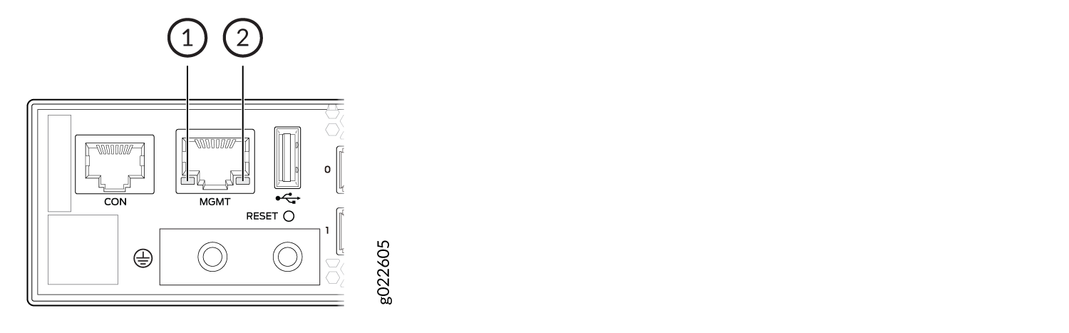
1 — Link activity LED | 2 — Status LED |
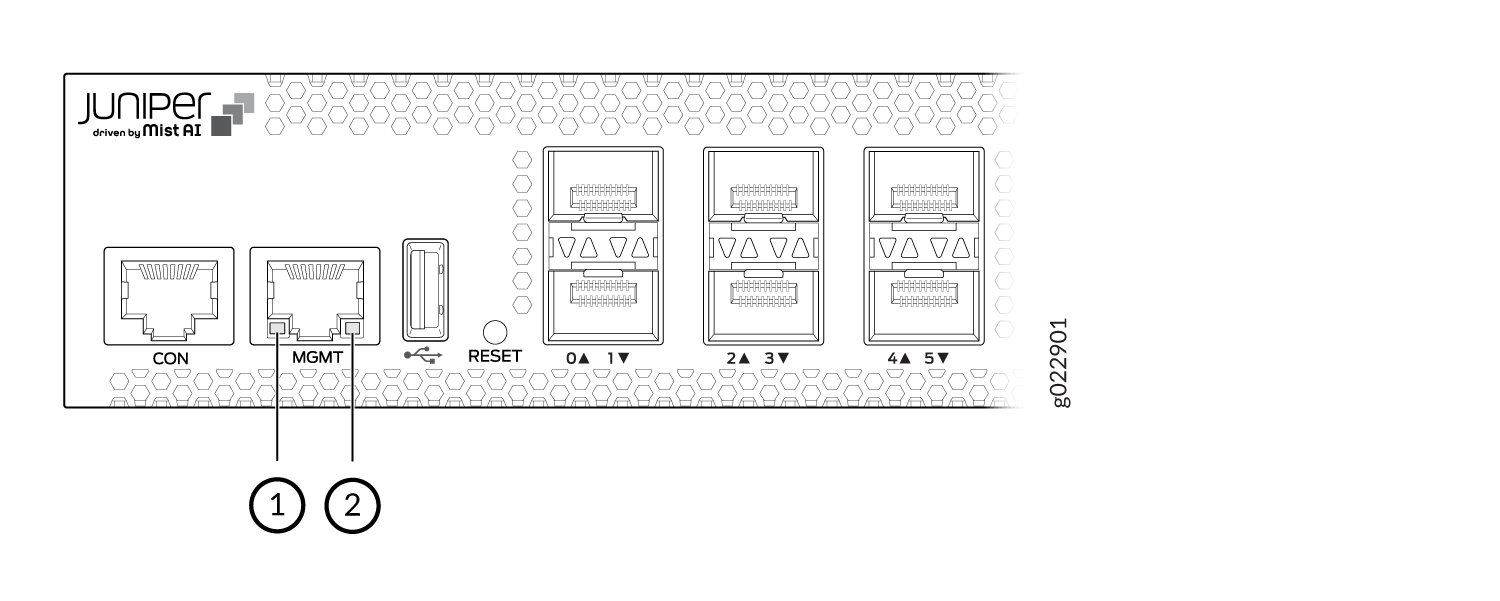
1 — Link activity LED | 2 — Status LED |
Table 5 describes the LEDs.
|
LED |
State and Description |
|---|---|
|
Link activity |
|
|
Status |
Indicates the speed:
|
LEDs on the RJ-45, SFP, and SFP+ Network Ports, QSFP28 Ports, and Extension Module Ports on EX4400 Switches
The RJ-45, small form-factor pluggable (SFP), and small form-factor pluggable plus (SFP+) network ports, SFP+, SFP28, and QSFP28 extension module ports, and QSFP28 ports on EX4400 switches have LEDs that show the link activity and status of the port.
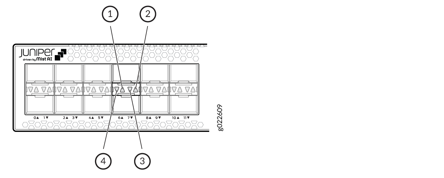
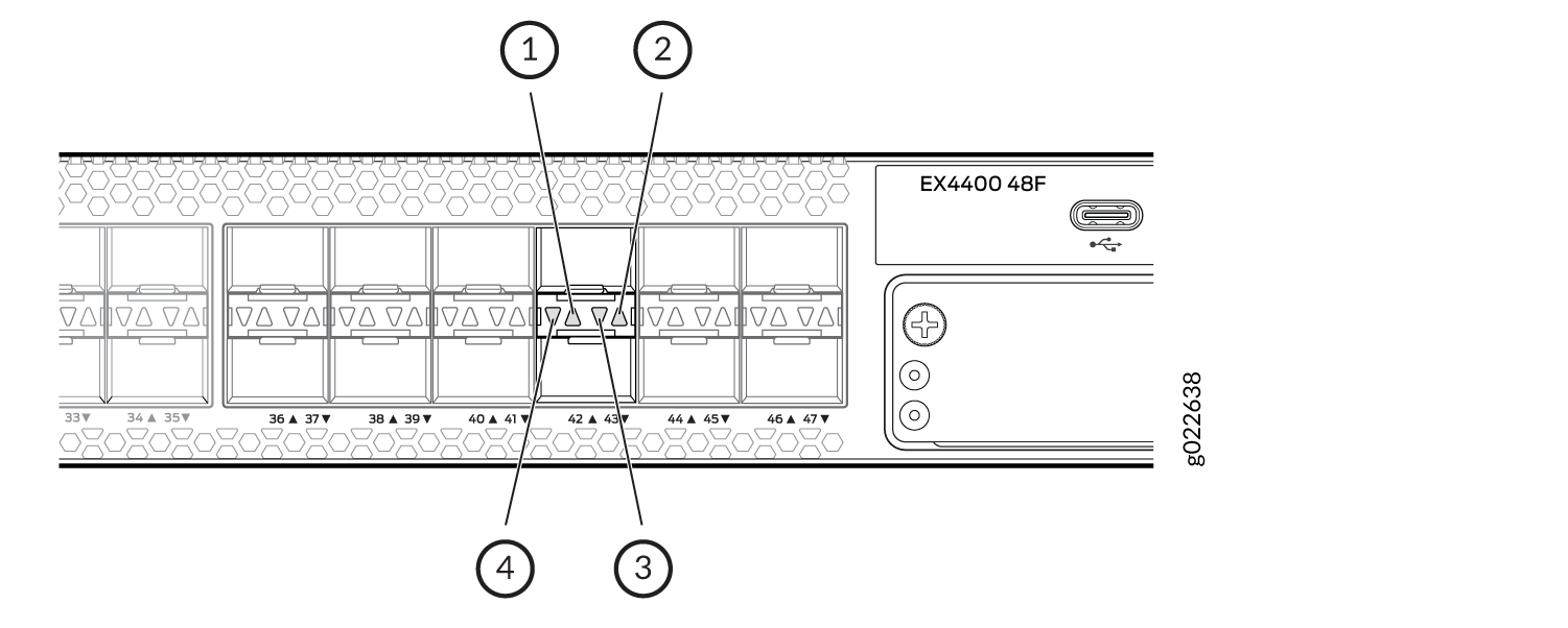
LEDs on the Network Ports
Figure 4 shows the LEDs on the RJ-45 network ports on EX4400-24T, EX4400-24P, EX4400-24MP, EX4400-48T, EX4400-48P, EX4400-48XP, EX4400-48MXP and EX4400-48MP switches. Figure 5 shows the LEDs on the SFP+ network ports on EX4400-24X switches. Figure 6 shows the LEDs on the SFP network ports on EX4400-48F switches. Figure 7 shows the LEDs on the SFP+ network ports on EX4400-48F switches.
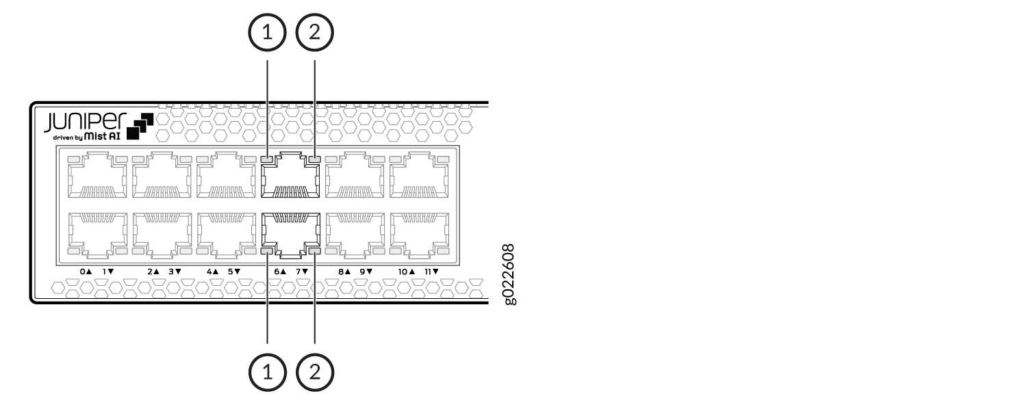
1 — Link activity LED | 2 — Status LED |
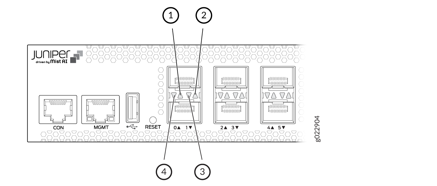
1 — Link activity LED for the upper port | 3 — Status LED for the lower port |
2 — Status LED for the upper port | 4 — Link activity LED for the lower port |
1 — Link activity LED for the upper port | 3 — Status LED for the lower port |
2 — Status LED for the upper port | 4 — Link activity LED for the lower port |
1 — Link activity LED for the upper port | 3 — Status LED for the lower port |
2 — Status LED for the upper port | 4 — Link activity LED for the lower port |
Table 6 describes the link activity LED on the network ports.
|
Color |
State and Description |
|---|---|
|
Green |
|
EX4400 switches have network port mode LEDs labeled SPD, DX, and EN on the right-hand side of the front panel; models with ports that support PoE-bt have an additional mode LED labeled POE (see Figure 8). These LEDs indicate the status of the network ports. Use the mode button on the right-hand side of the front panel to toggle the status LEDs to show the different port parameters for the network ports; the port parameter is indicated by the LED that is lit. Table 7 describes the status LEDs.
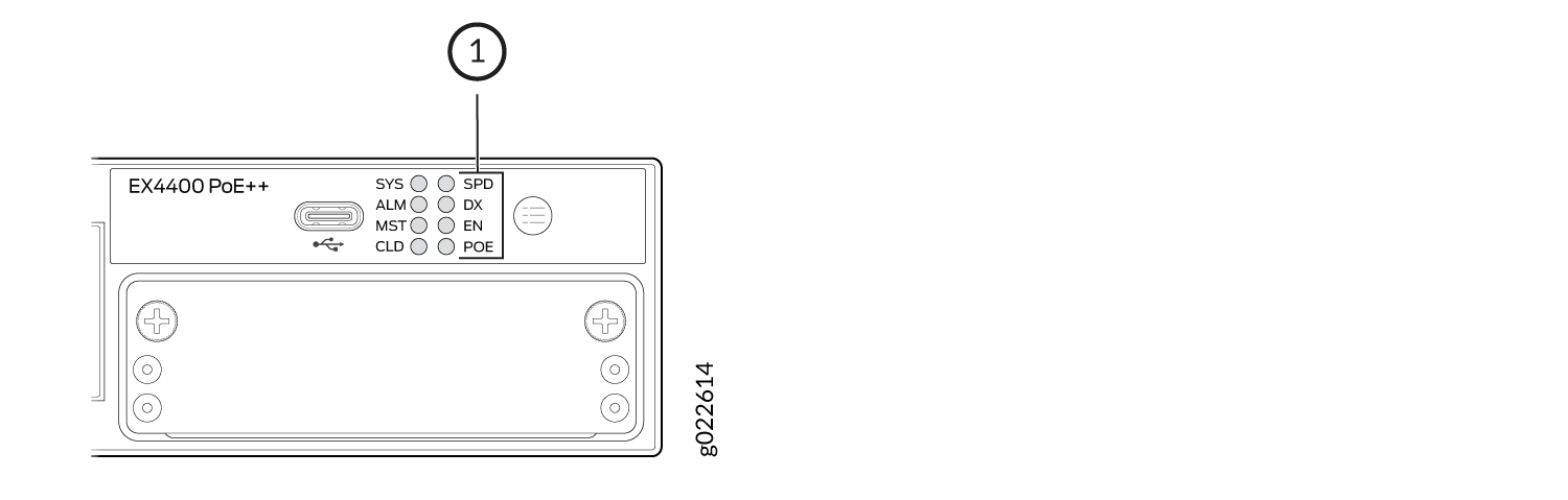
1 — Port Mode LEDs |
|
LED |
Color |
State and Description |
|---|---|---|
|
SPD |
Green |
Indicates the speed at which the RJ-45, SFP, and SFP+ network ports operate.
|
|
Amber |
The speed indicators for EX4400-24MP and EX4400-48MP are:
|
|
|
Blue |
The speed indicator for EX4400-24MP and EX4400-48MP is:
|
|
|
DX |
Green |
Indicates the duplex mode. The status indicators are:
|
|
EN |
Green |
Indicates the administrative status. The status indicators are:
|
|
POE |
Green |
Indicates the PoE-bt mode for ports that support PoE-bt. The status indicators are:
|
Table 8 describes the beacon functionality on the status LEDs on the RJ-45, SFP, and
SFP+ network ports when you execute the
                  request chassis
                            beacon
command.
|
LED |
Color |
State |
Description |
|---|---|---|---|
|
Status LEDs on all the ports |
Green |
Blinking, irrespective of the mode the ports are operating in. |
Helps identify the switch. |
|
Status LED on the applicable port |
Helps identify the port. |
LEDs on the QSFP28 Ports
Figure 9 and Figure 10 show the LEDs for the QSFP28 ports on EX4400 switch models except the EX4400-24X model. The two left LEDs are lit green when the ports operate as Virtual Chassis ports (VCPs).
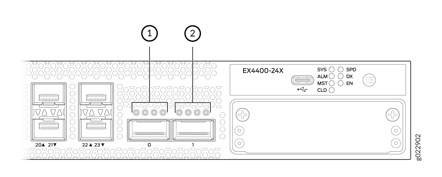
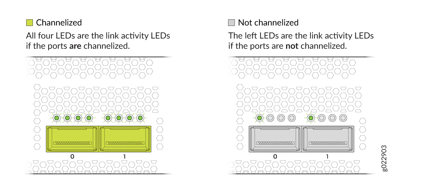
Figure 11 and Figure 12 show the LEDs for the QSFP28 ports on the EX4400-24X model. The LEDs on the extreme left hand side are lit green when the ports operate as VCPs. Table 9 describes the LED when the ports are configured as network ports.
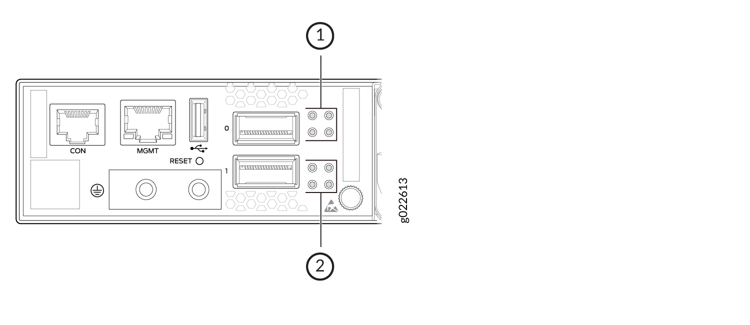
1 — LEDs for the upper port | 2 — LEDs for the lower port |
|
LED |
Color |
State and Description |
|---|---|---|
|
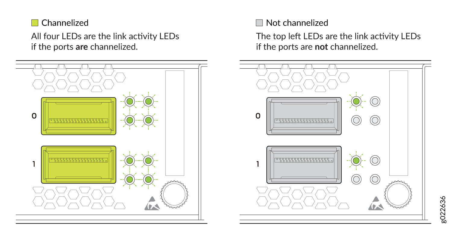
Link activity (non-channelized ports) |
Green |
|
|
Amber Note:
The support for 40-Gbps nonchannelized speed is available from Junos OS Release 22.1R1. |
|
|
|
All four LEDs (channelized ports). The LEDs correspond to the four channels. |
Green |
|
|
Amber |
|
LEDs on the Extension Module Ports
Figure 13 shows the LEDs on the 1x100GbE QSFP28 extension module port. Table 11 describes the LEDs on that port.
Figure 14 shows the LEDs on the 4x10GbE SFP+ extension module ports. Table 10 describes the link activity LED on those ports and Table 12 describes the status LED on those ports.
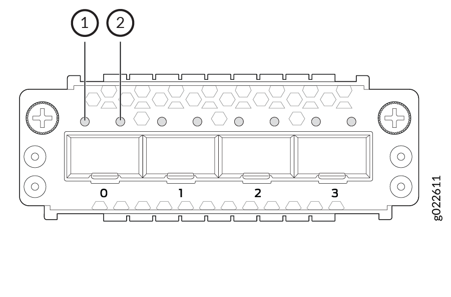
Figure 15 shows the LEDs on the 4x25GbE SFP28 extension module ports. Table 10 describes the link activity LED on those ports and Table 13 describes the status LED on those ports.
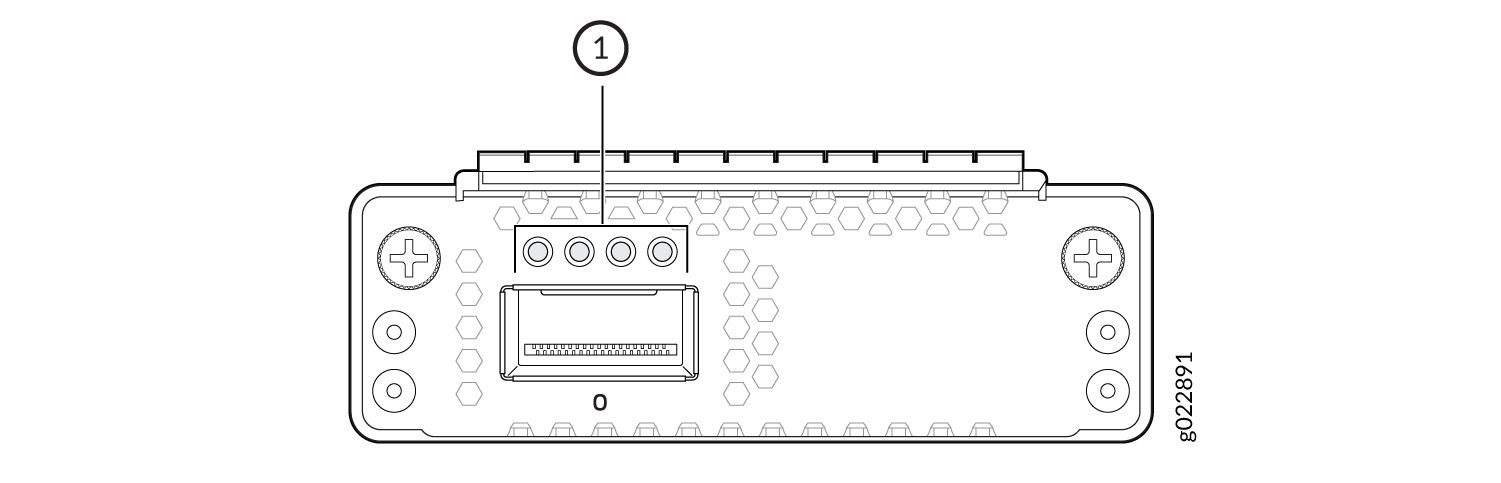
1 — LEDs |
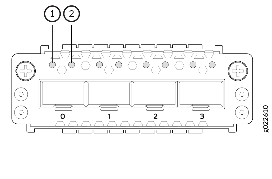
1 — Link activity LED | 2 — Status LED |
|
Color |
State and Description |
|---|---|
|
Green |
|
|
LED |
Color |
State and Description |
|---|---|---|
|
The LED on the extreme left |
Green |
|
|
Amber |
|
|
|
All four LEDs (channelized ports). The LEDs correspond to the four channels. |
Green |
|
|
Amber |
|
|
Color |
State and Description |
|---|---|
|
Green |
Indicates the speed. The speed indicators are:
|
1 — Link activity LED | 2 — Status LED |
|
Color |
State and Description |
|---|---|
|
Green |
Indicates the speed. The speed indicators are:
|