EX4400 Power System
AC Power Supply in EX4400 Switches
We ship the EX4400 switches with one power supply preinstalled in the rear panel of the switches. You can install up to two power supplies in the switch. You must order the second power supply and a power source cord separately. The power supply slots are numbered 0 and 1, and each slot has a power icon next to it. The power supplies support front-to-back or back-to-front airflow directions. The power supplies are fully redundant, load-sharing, and hot-removable and hot-insertable field-replaceable units (FRUs) when the second power supply is installed and running. You can remove and replace either one of the power supplies without powering off the switch or disrupting switch functions.
Do not mix:
-
AC and DC power supplies in the same chassis.
-
Power supplies with different airflow directions in the same chassis.
-
Fan modules with different airflow directions in the same chassis.
-
Power supplies and fan modules with different airflow directions in the same chassis.
This topic describes the AC power supplies that EX4400 switches support.
- Characteristics of the AC Power Supply
- Specifications of the AC Power Supplies Used in EX4400 Switches
- AC Power Supply Airflow
- Specifications of the Power Cord for AC Power Supplies for EX4400 Switches
- PoE-bt Budget Planning
Characteristics of the AC Power Supply
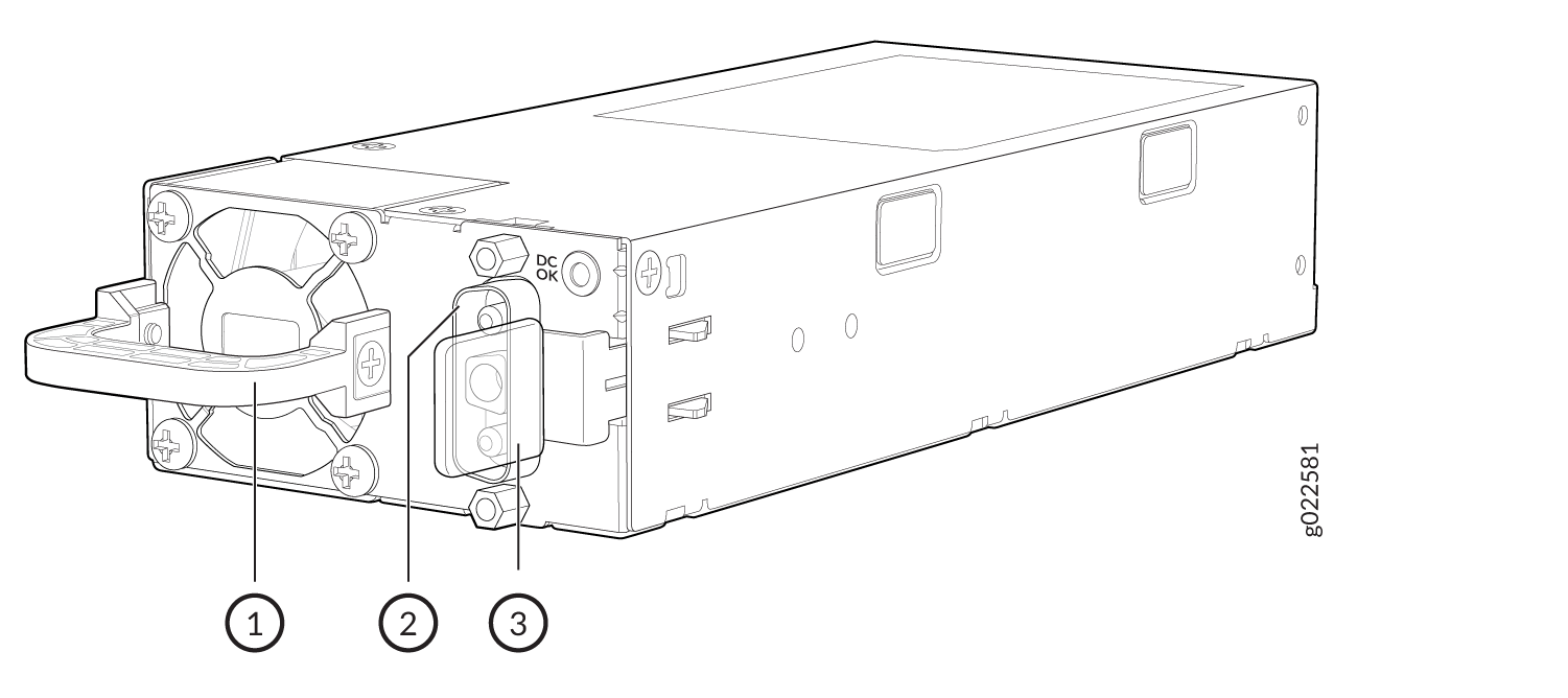
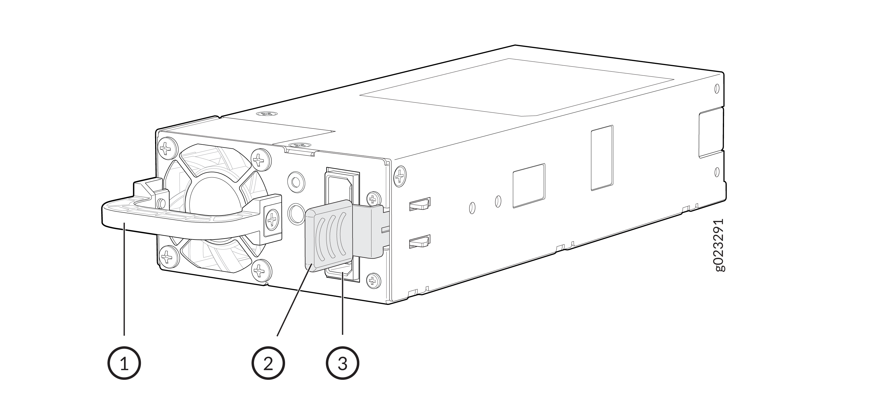
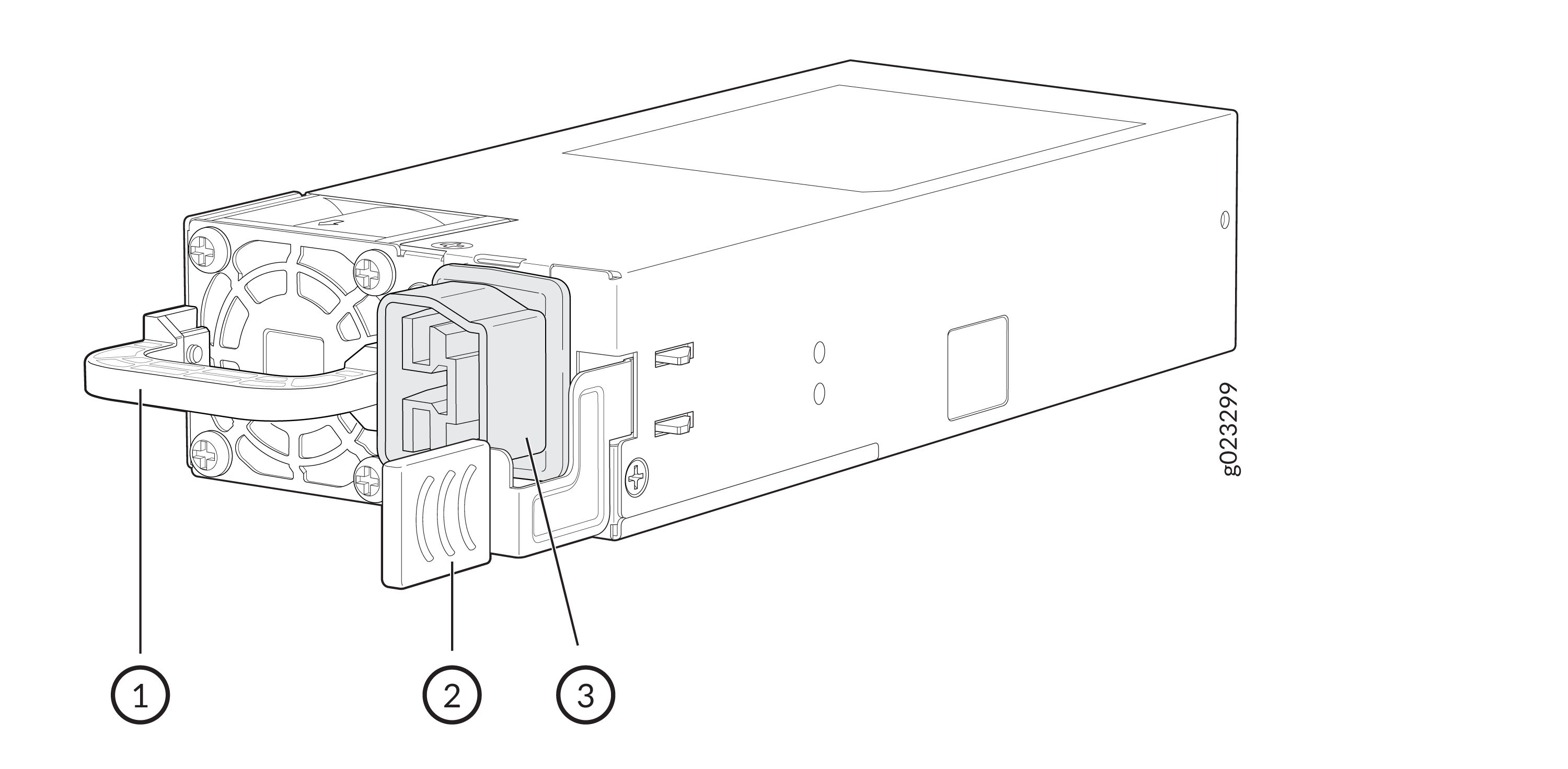
The AC power supplies for EX4400 switches come in 550-W, 1050-W, 1600-W, and 2000-W models. EX4400-24T, EX4400-24X, EX4400-48T, and EX4400-48F switches support 550-W AC power supplies (see Figure 1). EX4400-24P and EX4400-24MP switches support 1050W and 1600-W AC power supplies. These models support 1600-W AC power supply if you have Junos OS Release 22.3R1 or later installed. We ship the models with one 1050-W power supply. You can order the 1600-W power supply separately. EX4400-48P and EX4400-48MP switches support 1600-W AC power supplies. EX4400-48XP and EX4400-48MXP support 2000-W AC power supplies. You must not install different models of power supplies in the same chassis. The AC power supplies support IEEE 802.3bt Power over Ethernet (PoE-bt) in EX4400-24P, EX4400-24MP, EX4400-48P, EX4400-48XP, EX4400-48MXP, and EX4400-48MP models.
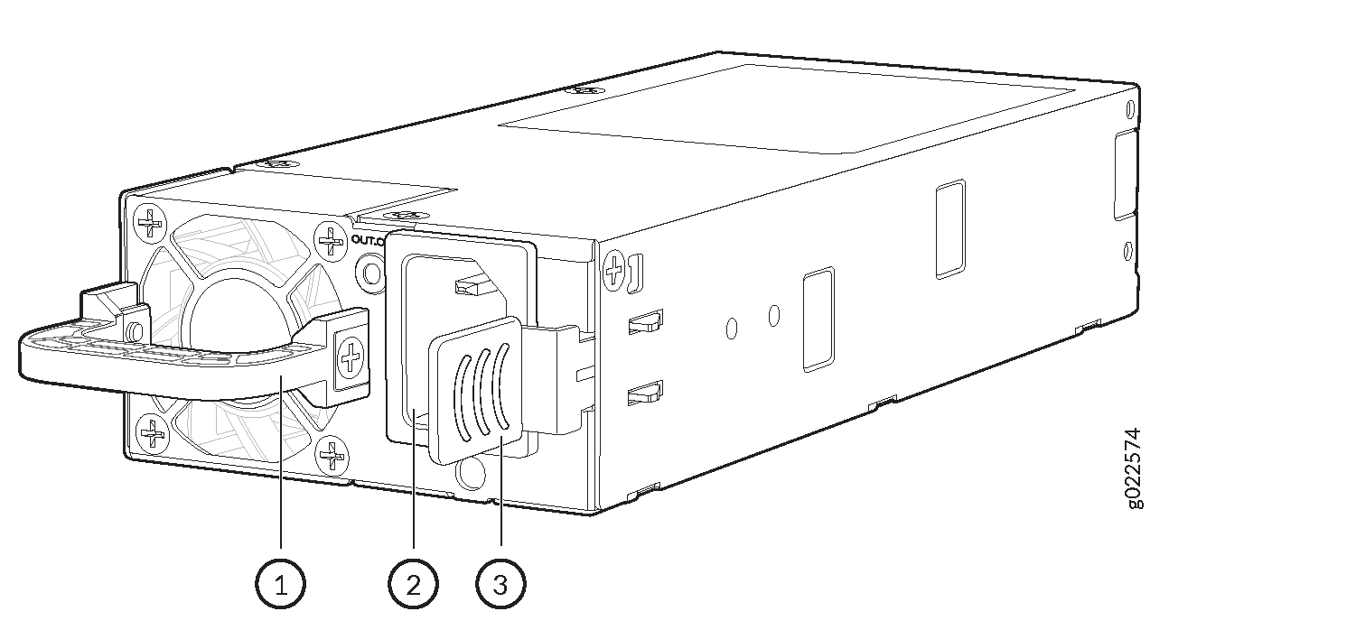
1 — Power supply handle | 3 — Power supply ejector lever |
2 — Power supply inlet |
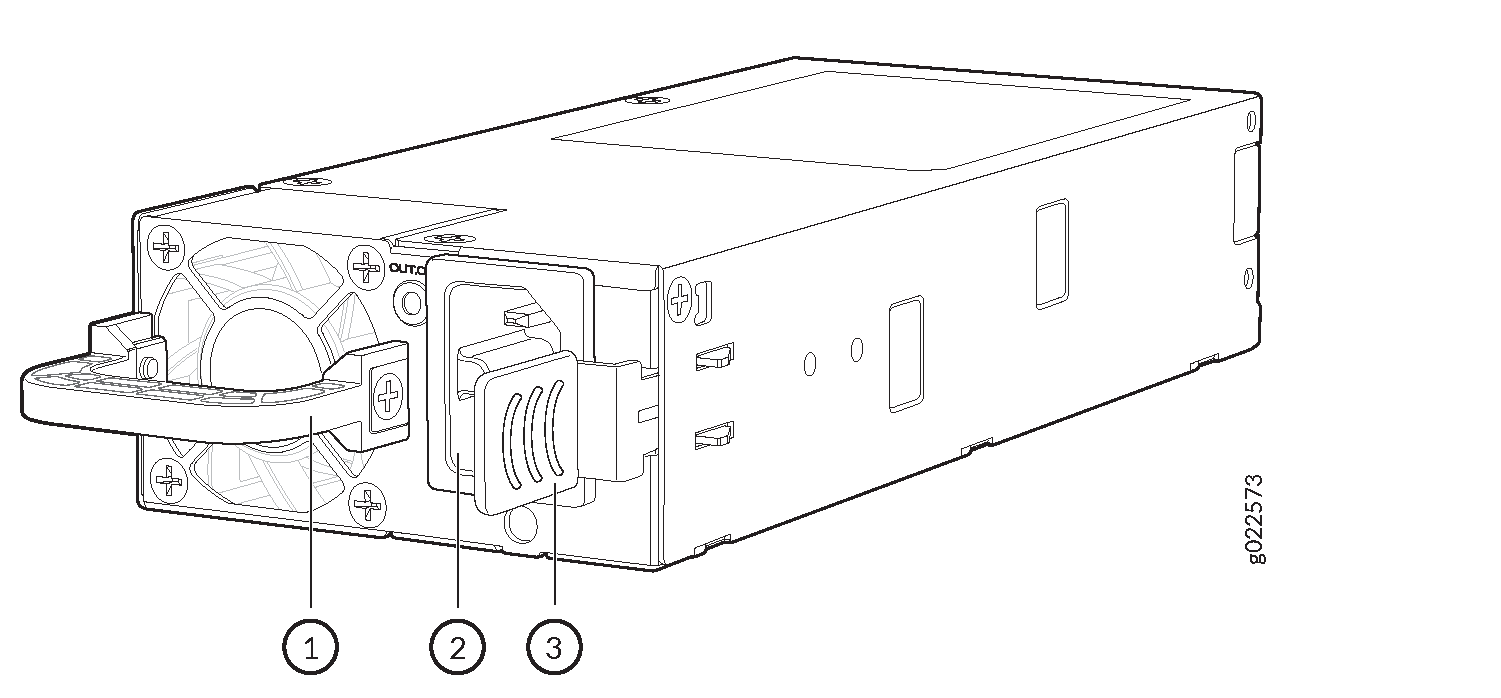
1 — Power supply handle | 3 — Power supply ejector lever |
2 — Power supply inlet |
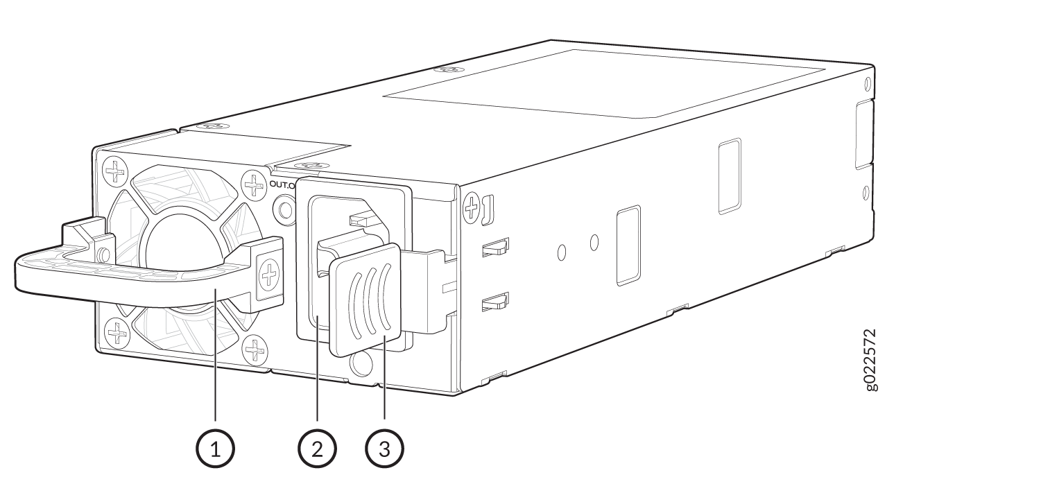
1 — Power supply handle | 3 — Power supply ejector lever |
2 — Power supply inlet |
1 — Power supply handle | 3 — Power supply ejector lever |
2 — Power supply inlet |
Table 1 lists the details of the 550-W, 1050-W, 1600-W, and 2000-W AC power supplies used in EX4400 switches.
|
Details |
550-W AC Power Supply |
1050-W AC Power Supply |
1600-W AC Power Supply |
2000-W AC Power Supply |
|
|---|---|---|---|---|---|
|
Model number |
|
JPSU-1050-C-AC-AFO |
JPSU-1600-C-AC-AFO |
JPSU-2000-C-AC-AFO |
|
|
Minimum installed in chassis |
1 |
1 |
1 |
1 |
|
|
Maximum installed in chassis |
2 |
2 |
2 |
2 |
|
|
AC appliance inlet Note:
Each AC appliance inlet requires a dedicated AC power feed. |
Number |
1 |
1 |
1 |
1 |
|
Type |
IEC-320-C13 |
IEC-320-C15 |
IEC-320-C15 |
IEC-320-C15 |
|
|
Power supply status LED |
OUT.OK |
OUT.OK |
OUT.OK |
OUT.OK |
|
To prevent electrical injury while installing or removing AC power supplies, carefully follow instructions in Install a Power Supply in an EX4400 Switch and Remove a Power Supply from an EX4400 Switch.
Specifications of the AC Power Supplies Used in EX4400 Switches
-
Table 2 provides the power supply specifications of the 550-W AC power supplies.
-
Table 3 provides the power supply specifications of the 1050-W AC power supplies.
-
Table 4 provides the power supply specifications of the 1600-W AC power supplies.
-
Table 5 provides the power supply specifications of the 2000-W AC power supplies.
|
Item |
Specification |
|---|---|
|
AC input voltage |
|
|
AC input line frequency |
47–63 Hz |
|
AC input current rating |
|
|
Output power |
550 W |
|
Efficiency |
80-plus platinum efficiency certified |
|
Item |
Specification |
|---|---|
|
AC input voltage |
|
|
AC input line frequency |
50–60 Hz |
|
AC input current rating |
|
|
Output power |
1050 W |
|
Efficiency |
80-plus platinum efficiency certified |
|
Item |
Specification |
|---|---|
|
AC input voltage |
|
|
AC input line frequency |
50–60 Hz |
|
AC input current rating |
|
|
Output power |
1600 W |
|
Efficiency |
80-plus platinum efficiency certified |
|
Item |
Specification |
|---|---|
|
AC input voltage |
|
|
AC input line frequency |
50–60 Hz |
|
AC input current rating |
|
|
Output power |
2000 W |
|
Efficiency |
80-plus platinum efficiency certified |
AC Power Supply Airflow
Each power supply has its own fan and is cooled by its own internal cooling system. EX4400 switches support power supplies with the following airflow directions:
-
Front-to-back (cold air enters through the vents on the front panel of the switch and hot air exhausts through the vents on the rear panel), indicated by the AIR OUT label and the orange handle.
-
Back-to-front (cold air enters through the vents on the rear panel of the switch and hot air exhausts through the vents on the front panel), indicated by the AIR IN label and the Juniper Azure Blue handle.
Table 6 lists the AC power supply models and the direction of airflow in them.
|
Model |
Direction of Airflow |
|---|---|
|
Front-to-back—that is, cold air enters the chassis through the vents on the front panel of the chassis and hot air exhausts through the vents on the rear panel of the chassis, indicated by the AIR OUT label and the orange handle. |
|
JPSU-550-C-AC-AFI |
Back-to-front—that is, cold air enters the chassis through the vents on the rear panel of the chassis and hot air exhausts through the vents on the front panel of the chassis, indicated by the AIR IN label and the Juniper Azure Blue handle. |
Specifications of the Power Cord for AC Power Supplies for EX4400 Switches
Each AC power supply has a single AC appliance inlet that requires a dedicated AC power feed. A detachable AC power cord is supplied with each AC power supply. We ship the 550-W AC power supplies with AC power cords with the C13 coupler type and the 1050-W, 1600-W AC, and 2000-W AC power supplies with the C15 coupler type as described by International Electrotechnical Commission (IEC) standard 60320. The plug end of the power cord fits into the power source outlet that is standard for your geographical location.
In North America, AC power cords must not exceed 14.75 ft (4.5 m) in length, to comply with National Electrical Code (NEC) Section 400-8 (NFPA 75, 5-2.2) and Canadian Electrical Code (CEC) Section 4-010(3).
Table 7 lists the AC power cords specifications provided for the 550-W power supplies for each country or region.
|
Country/Region |
Electrical Specifications |
Plug Standards |
Juniper Model Number |
Graphic |
|---|---|---|---|---|
|
Argentina |
250 VAC, 10 A, 50 Hz |
IRAM 2073 Type RA/3 |
CBL-EX-PWR-C13-AR |
No graphic available |
|
Australia |
250 VAC, 10 A, 50 Hz |
AS/NZS 3112 Type SAA/3 |
CBL-EX-PWR-C13-AU |
|
|
Brazil |
250 VAC, 10 A, 50 Hz |
NBR 14136 Type BR/3 |
CBL-EX-PWR-C13-BR |
No graphic available |
|
China |
250 VAC, 10 A, 50 Hz |
GB 1002-1996 Type PRC/3 |
CBL-EX-PWR-C13-CH |
|
|
Europe (except Italy, Switzerland, and United Kingdom) |
250 VAC, 10 A, 50 Hz |
CEE (7) VII Type VIIG |
CBL-EX-PWR-C13-EU |
|
|
India |
250 VAC, 10 A, 50 Hz |
IS 1293 Type IND/3 |
CBL-EX-PWR-C13-IN |
No graphic available |
|
Israel |
250 VAC, 10 A, 50 Hz |
SI 32/1971 Type IL/3G |
CBL-EX-PWR-C13-IL |
|
|
Italy |
250 VAC, 10 A, 50 Hz |
CEI 23-16 Type I/3G |
CBL-EX-PWR-C13-IT |
|
|
Japan |
125 VAC, 12 A, 50 Hz or 60 Hz |
JIS 8303 |
CBL-EX-PWR-C13-JP |
|
|
Korea |
250 VAC, 10 A, 50 Hz or 60 Hz |
CEE (7) VII Type VIIGK |
CBL-EX-PWR-C13-KR |
|
|
North America |
125 VAC, 13 A, 60 Hz |
NEMA 5-15 Type N5-15 |
CBL-EX-PWR-C13-US |
|
|
South Africa |
250 VAC, 10 A, 50 Hz |
SABS 164/1:1992 Type ZA/3 |
CBL-EX-PWR-C13-SA |
|
|
Switzerland |
250 VAC, 10 A, 50 Hz |
SEV 6534-2 Type 12G |
CBL-EX-PWR-C13-SZ |
No graphic available |
|
Taiwan |
125 VAC, 10 A, 50 Hz |
NEMA 5-15P Type N5-15P |
CBL-EX-PWR-C13-TW |
|
|
United Kingdom |
250 VAC, 10 A, 50 Hz |
BS 1363/A Type BS89/13 |
CBL-EX-PWR-C13-UK |
|
Table 8 lists the specifications of the power cords used to connect EX4400 switches to C13 Power Strips.
|
Country/Region |
Electrical Specifications |
Juniper Model Number |
|---|---|---|
|
USA, China, Japan, Europe, South Korea, Australia |
250 VAC, 10 A, 50 Hz |
CBL-EX-PWR-C13-C14 |
|
Country/Region |
Electrical Specifications |
Plug Standards |
Juniper Model Number |
|---|---|---|---|
|
Argentina |
250 VAC, 10 A, 50 Hz |
IRAM 2073 Type RA/3 |
CBL-PWR-C15M-HITEMP-AR |
|
Australia |
250 VAC, 10 A, 50 Hz |
AS/NZZS 3112-2000 Type SAA/3 |
CBL-PWR-C15M-HITEMP-AU |
|
Brazil |
250 VAC, 10 A, 50 Hz |
NBR 14136 Type BR/3 |
CBL-PWR-C15M-HITEMP-BR |
|
China |
250 VAC, 10 A, 50 Hz |
GB2099, GB1002 Type PRC/3 |
CBL-PWR-C15M-HITEMP-CH |
|
Europe (except Italy, Switzerland, and United Kingdom) |
250 VAC, 10 A, 50 Hz |
CEE (7) VII Type VIIG |
CBL-PWR-C15M-HITEMP-EU |
|
Israel |
250 VAC, 10 A, 50 Hz |
SI 32 Type IL/3G |
CBL-PWR-C15M-HITEMP-IL |
|
India |
250 VAC, 10 A, 50 Hz |
SABS 164/1:1992 Type ZA/3 |
CBL-PWR-C15M-HITEMP-IN |
|
Italy |
250 VAC, 10 A, 50 Hz |
CEI 23-16 Type I/3G |
CBL-PWR-C15M-HITEMP-IT |
|
Japan |
125 VAC, 15 A, 50 Hz or 60 Hz |
JIS 8303 Type 498GJ |
CBL-PWR-C15M-HITEMP-JP |
|
Korea |
250 VAC, 10 A, 50 Hz |
CEE (7) VII Type VIIG |
CBL-PWR-C15M-HITEMP-KR |
|
South Africa |
250 VAC, 10 A, 50 Hz |
SABS 164/1:1992 Type ZA/3 |
CBL-PWR-C15M-HITEMP-SA |
|
North America |
125 VAC, 15 A, 60 Hz |
NEMA 5-15 Type N5/15 |
CBL-PWR-C15M-HITEMP-US |
|
Switzerland |
250 VAC, 10 A, 50 Hz |
SEV 1011 / 6534-2 Type 12G |
CBL-PWR-C15M-HITEMP-SZ |
|
United Kingdom |
250 VAC, 10 A, 50 Hz |
BS 1363/A Type BS89/13 |
CBL-PWR-C15M-HITEMP-UK |
Table 10 lists the specifications of the power cords used to connect EX4400 switches to C13 Power Strips.
|
Country/Region |
Electrical Specifications |
Juniper Model Number |
|---|---|---|
|
Europe |
250 VAC, 10 A, 50 Hz |
CBL-PWR-C15-C14-EU |
| North America | 125 VAC, 15 A, 60 Hz | CBL-PWR-C15-C14-US |
You must use the AC power cord for the EX4400 switch with this switch only. Do not use the cord with any other product.
Power cords must not block access to switch components.
PoE-bt Budget Planning
Table 11 lists the PoE-bt power available in an EX4400-24P switch.
| Power Supply | Input Voltage | Available PoE-bt Power | |
|---|---|---|---|
| 1 | 2 | ||
|
1050 W |
– |
110 V |
783 W |
|
230 V |
783 W |
||
|
1050 W |
1050 W |
110 V |
1806 W |
|
230 V |
1806 W |
||
|
1600 W |
– |
110 V |
783 W |
|
230 V |
1320 W |
||
|
1600 W |
1600 W |
110 V |
1806 W |
|
230 V |
2160 W |
||
Table 12 lists the PoE-bt power available in an EX4400-24P switch if Junos OS Release 22.2R1 or earlier is installed in the switch.
|
Power Supply |
Input Voltage |
Available PoE-bt Power |
|
|---|---|---|---|
|
1 |
2 |
||
|
1050 W |
– |
110 V |
788 W |
|
230 V |
788 W |
||
|
1050 W |
1050 W |
110 V |
1440 W |
|
230 V |
1440 W |
||
Table 13 lists the PoE-bt power available in an EX4400-24MP switch.
|
Power Supply |
Input Voltage |
Available PoE-bt Power |
|
|---|---|---|---|
|
1 |
2 |
||
|
1050 W |
– |
110 V |
753 W |
|
230 V |
753 W |
||
|
1050 W |
1050 W |
110 V |
1776 W |
|
230 V |
1776 W |
||
|
1600 W |
– |
110 V |
753 W |
|
230 V |
1290 W |
||
|
1600 W |
1600 W |
110 V |
1776 W |
|
230 V |
2160 W |
||
Table 14 lists the PoE-bt power available in an EX4400-24MP switch if Junos OS Release 22.2R1 or earlier is installed in the switch.
|
Power Supply |
Input Voltage |
Available PoE-bt Power |
|
|---|---|---|---|
|
1 |
2 |
||
|
1050 W |
– |
110 V |
780 W |
|
230 V |
780 W |
||
|
1050 W |
1050 W |
110 V |
1800 W |
|
230 V |
1800 W |
||
Table 15 lists the PoE-bt power available in an EX4400-48P switch.
|
Power Supply |
Input Voltage |
Available PoE-bt Power |
|
|---|---|---|---|
|
1 |
2 |
||
|
1600 W |
– |
110 V |
773 W |
|
230 V |
1310 W |
||
|
1600 W |
1600 W |
110 V |
1796 W |
|
230 V |
2200 W |
||
Table 16 lists the PoE-bt power available in an EX4400-48P switch if Junos OS Release 22.2R1 or earlier is installed in the switch.
|
Power Supply |
Input Voltage |
Available PoE-bt Power |
|
|---|---|---|---|
|
1 |
2 |
||
|
1600 W |
– |
110 V |
768 W |
|
230 V |
1290 W |
||
|
1600 W |
1600 W |
110 V |
1440 W |
|
230 V |
1800 W |
||
Table 17 lists the PoE-bt power available in an EX4400-48XP switch.
|
Power Supply |
Input Voltage |
Available PoE-bt Power |
|
|---|---|---|---|
|
1 |
2 |
||
|
2000 W |
– |
110 V |
724 W |
|
230 V |
1650 W |
||
|
2000 W |
2000 W |
110 V |
1748 W |
|
230 V |
3600 W |
||
Table 18 lists the PoE-bt power available in an EX4400-48MXP switch.
|
Power Supply |
Input Voltage |
Available PoE-bt Power |
|
|---|---|---|---|
|
1 |
2 |
||
|
2000 W |
– |
110 V |
724 W |
|
230 V |
1650 W |
||
|
2000 W |
2000 W |
110 V |
1748 W |
|
230 V |
3600 W |
||
Table 19 lists the PoE-bt power available in an EX4400-48MP switch.
|
Power Supply |
Input Voltage |
Available PoE-bt Power |
|
|---|---|---|---|
|
1 |
2 |
||
|
1600 W |
– |
110 V |
723 W |
|
230 V |
1260 W |
||
|
1600 W |
1600 W |
110 V |
1746 W |
|
230 V |
2200 W |
||
Table 20 lists the PoE-bt power available in an EX4400-48MP switch if Junos OS Release 22.2R1 or earlier is installed in the switch.
|
Power Supply |
Input Voltage |
Available PoE-bt Power |
|
|---|---|---|---|
|
1 |
2 |
||
|
1600 W |
– |
110 V |
750 W |
|
230 V |
1300 W |
||
|
1600 W |
1600 W |
110 V |
1800 W |
|
230 V |
2200 W |
||
DC Power Supply in EX4400 Switches
We ship the EX4400 switches with one power supply installed in the rear panel of the switches. You can install up to two power supplies in the switch. You must order the second power supply and a power source cord (part number: CBL-JNP-PWR-DSUB) separately. The power supply slots are numbered 0 and 1 and each slot has a power icon next to it. The power supplies support front-to-back or back-to-front airflow directions. The power supplies are fully redundant, load-sharing, and hot-removable and hot-insertable field-replaceable units (FRUs) when the second power supply is installed and running: You can remove and replace either one of them without powering off the switch or disrupting switch functions.
Do not mix:
-
AC and DC power supplies in the same chassis.
-
Power supplies with different airflow directions in the same chassis.
-
Fan modules with different airflow directions in the same chassis.
-
Power supplies and fan modules with different airflow directions in the same chassis.
This topic describes the DC power supplies that EX4400 switches support.
- Characteristics of the DC Power Supply
- Specifications of the DC Power Supplies Used in EX4400 Switches
- EX4400 DC Power Cable Specification
- DC Power Supply Airflow
- PoE-bt Budget Planning (DC power supply)
Characteristics of the DC Power Supply
DC-powered EX4400-24T, EX4400-24X, EX4400-48T, and EX4400-48F switches support 550-W DC power supplies. See Figure 5.
1 — Power supply handle | 3 — Power supply ejector lever |
2 — Power supply inlet |
DC-powered EX4400-24P, EX4400-24MP, EX4400-48P, EX4400-48MP, EX4400-48XP, and EX4400-48MXP support 2000-W DC power supplies. See Figure 6.
1 — Power supply handle | 3 — Power supply ejector lever |
2 — Power supply inlet |
The EX4400-48F-S switch supports the 550-W VDC power supplies.
1 — Power supply handle | 3 — Power supply ejector lever |
2 — Power supply inlet |
Table 21 lists the details of the 550 W DC power supply used in EX4400 switches. Table 22 lists the details of the 550 W VDC power supply used in the EX4400-48F-S switch, and Table 23 lists the details of the 2000 W DC power supply used in EX4400 switches.
|
Details |
550-W DC Power Supplies |
|
|---|---|---|
|
Model number |
|
|
|
Minimum installed in chassis |
1 |
|
|
Maximum installed in chassis |
2 |
|
|
Power supply status LED |
DC.OK |
|
|
Details |
550-W VDC Power Supplies |
|
|---|---|---|
|
Model number |
|
|
|
Minimum installed in chassis |
1 |
|
|
Maximum installed in chassis |
2 |
|
|
Power supply status LED |
OUT.OK |
|
|
Details |
2000-W DC Power Supplies |
|
|---|---|---|
|
Model number |
|
|
|
Minimum installed in chassis |
1 |
|
|
Maximum installed in chassis |
2 |
|
|
Power supply status LED |
DC.OK |
|
To prevent electrical injury while installing or removing DC power supplies, carefully follow instructions in Install a Power Supply in an EX4400 Switch and Remove a Power Supply from an EX4400 Switch.
Specifications of the DC Power Supplies Used in EX4400 Switches
Table 24 provides the power supply specifications of the 550-W DC power supplies.
Table 25 provides the power supply specifications of the 550-W VDC power supplies.
Table 26 provides the power supply specifications of the 2000-W DC power supplies.
|
Item |
Specification |
|---|---|
|
DC input voltage |
Rated operating voltage: –48 VDC through –60 VDC |
|
DC input current rating |
13 A |
|
Output power |
550 W |
|
Item |
Specification |
|---|---|
|
DC input voltage |
Rated operating voltage: 120–310 VDC |
|
DC input current rating |
7 A |
|
Output power |
550 W |
|
Item |
Specification |
|---|---|
|
DC input voltage |
Rated operating voltage: –48 VDC through –60 VDC |
|
DC input current rating |
53 A |
|
Output power |
2000 W |
EX4400 DC Power Cable Specification
EX4400 DC power supplies require a D-Sub 3W3- type connector. The three pins on the connector provide –48 VDC input (–), return (+), and ground connections to the power supply.
Regardless which DC power cable you use, you must connect the EX4400 to earth ground before you connect it to power.
DC power cables, each 4 m (approximately 13.1 ft) long, are supplied with the EX4400 switches. The provided cables include the three-pin connector on one end and three insulated wires at the opposite end, for connection to the site’s DC power distribution system.
EX4400 DC Power Cable Specification lists the specifications for the EX4400 DC power cables.
Table 28 lists the power cable specifications of the 550-W VDC PSU used in the EX4400-48F-S switch model.
Table 29 lists the specifications for the EX4400 2000-W DC PSU power cable.
|
Juniper Model |
Wire Function |
Insulation Color |
Wire Size |
|---|---|---|---|
|
CBL-JNP-PWR-DSUB (straight cable) |
–48 VDC input (–) |
Blue |
8 AWG (8.4 mm²), 90° C |
|
Return (+) |
Black |
8 AWG (8.4 mm²), 90° C |
|
|
Ground |
Green and yellow |
8 AWG (8.4 mm²), 90° C |
|
|
CBL-JNP-PWR-DSUB4 (straight cable) |
–48 VDC input (–) |
Blue |
12 AWG (3.31 mm²), 90° C |
|
Return (+) |
Black |
12 AWG (3.31 mm²), 90° C |
|
|
Ground |
Green and yellow |
12 AWG (3.31 mm²), 90° C |
|
Country |
Electrical Specifications |
Juniper Model Number |
Wire Insulation Color |
||
|---|---|---|---|---|---|
|
Positive/Neutral |
Negative |
Ground |
|||
|
Argentina |
HVDC, 25A, 400V, 3m, SDG Straight Single End plug to Bare wire |
CBL-EX-PWR-SDG-INT |
Blue |
Brown |
Green/Yellow |
|
Australia |
|||||
|
New Zealand |
|||||
|
China |
|||||
|
Europe |
|||||
|
South Korea |
|||||
|
Italy |
|||||
|
Switzerland |
|||||
|
Israel |
|||||
|
South Africa |
|||||
|
North America |
HVDC, 25A, 400V, 3m, SDG Straight Single End plug to Bare wire |
CBL-EX-PWR-SDG-US |
White |
Black |
Green |
|
India |
HVDC, 25A, 400V, 3m, SDG Straight Single End plug to Bare wire |
CBL-EX-PWR-SDG-IN |
Black |
Red |
Green/Yellow |
|
Taiwan |
AC, SDG, Bare wire, 15A, 400V, 3m, Straight |
CBL-EX-PWR-SDG-TW |
White |
Black |
Green |
|
Japan |
AC, SDG, Bare wire, 15A, 400V, 3m, Straight |
CBL-EX-PWR-SDG-JP |
White |
Black |
Green/Yellow |
|
Juniper Model |
Wire Function |
Insulation Color |
Wire Size |
|---|---|---|---|
|
CBL-PWR-2K-DSUB4 |
–48 VDC input (V–) |
Black |
6 AWG (13 mm²), 85° C |
|
Return (V+) |
Red |
6 AWG (13 mm²), 85° C |
CBL-JNP-PWR-DSUB4 (straight cable) can be separately ordered.
CBL-PWR-2K-DSUB4 is 3.9 metres in length.
The connector has 3 pins and the middle one is the Ground.
For field-wiring connections, use copper conductors only.
Power cables must not block access to components or drape where people could trip on them.
You must ensure that power connections maintain the proper polarity. The power source cables might be labeled (+) and (–) to indicate their polarity. There is no standard color coding for DC power cables. The color coding used by the external DC power source at your site might be different from the color coding for the leads on the DC power cable provided with the chassis.
DC Power Supply Airflow
Each power supply has its own fan and is cooled by its own internal cooling system. EX4400 switches support power supplies with the following airflow directions:
-
Front-to-back (cold air enters through the vents on the front panel of the switch and hot air exhausts through the vents on the rear panel), indicated by the AIR OUT label and the orange handle.
-
Back-to-front (cold air enters through the vents on the rear panel of the switch and hot air exhausts through the vents on the front panel), indicated by the AIR IN label and the Juniper Azure Blue handle.
Table 30 lists the DC power supply models and the direction of airflow in them.
|
Model |
Direction of Airflow |
|---|---|
|
JPSU-550-C-DC-AFO JPSU-2000-C-DC-AFO JPSU-550-C-VDC-AFO |
Front-to-back—that is, cold air enters the chassis through the vents on the front panel of the chassis and hot air exhausts through the vents on the rear panel of the chassis, indicated by the AIR OUT label and the orange handle. |
|
JPSU-550-C-DC-AFI |
Back-to-front—that is, cold air enters the chassis through the vents on the rear panel of the chassis and hot air exhausts through the vents on the front panel of the chassis, indicated by the AIR IN label and the Juniper Azure Blue handle. |
PoE-bt Budget Planning (DC power supply)
Table 11 lists the PoE-bt power available in an EX4400-24P switch with DC power supply.
| Power Supply | Available PoE-bt Power | |
|---|---|---|
| 1 | 2 | |
|
2000 W |
– |
1710 W |
|
2000 W |
2000 W |
2160 W |
Table 13 lists the PoE-bt power available in an EX4400-24MP switch with DC power supply.
|
Power Supply |
Available PoE-bt Power |
|
|---|---|---|
|
1 |
2 |
|
|
2000 W |
– |
1680 W |
|
2000 W |
2000 W |
2160 W |
Table 15 lists the PoE-bt power available in an EX4400-48P switch with DC power supply.
|
Power Supply |
Available PoE-bt Power |
|
|---|---|---|
|
1 |
2 |
|
|
2000 W |
– |
1700 W |
|
2000 W |
2000 W |
2200 W |
Table 34 lists the PoE-bt power available in an EX4400-48XP switch with DC power supply.
| Power Supply | Available PoE-bt Power | |
|---|---|---|
| 1 | 2 | |
|
2000 W |
– |
1650 W |
|
2000 W |
2000 W |
3600 W |
Table 35 lists the PoE-bt power available in an EX4400-48MXP switch with DC power supply.
| Power Supply | Available PoE-bt Power | |
|---|---|---|
| 1 | 2 | |
|
2000 W |
– |
1650 W |
|
2000 W |
2000 W |
3600 W |
Table 19 lists the PoE-bt power available in an EX4400-48MP switch with DC power supply.
|
Power Supply |
Available PoE-bt Power |
|
|---|---|---|
|
1 |
2 |
|
|
2000 W |
– |
1650 W |
|
2000 W |
2000 W |
2200 W |
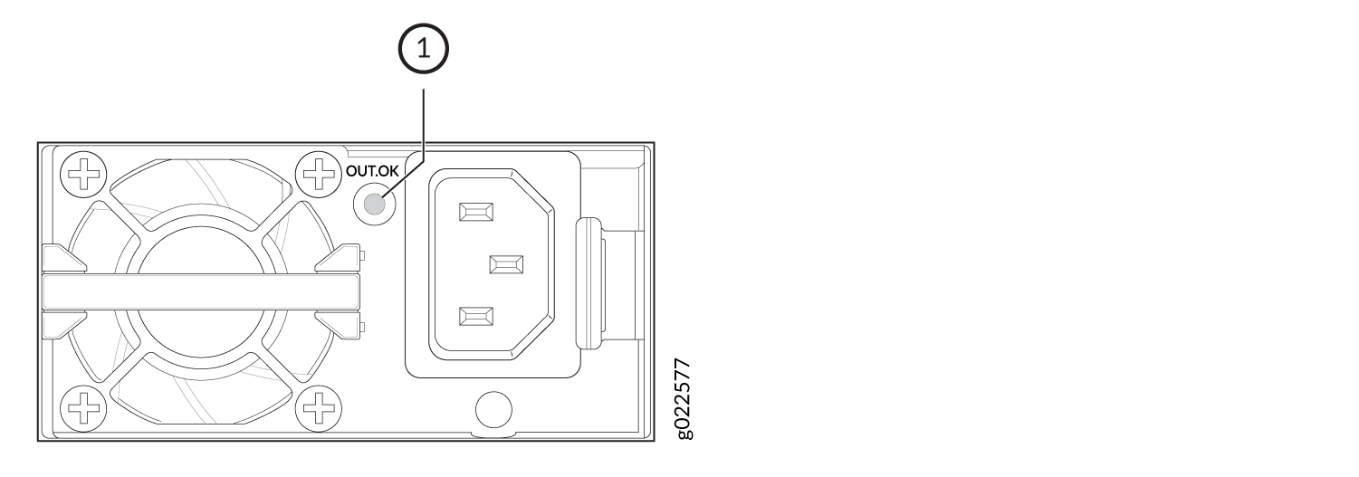
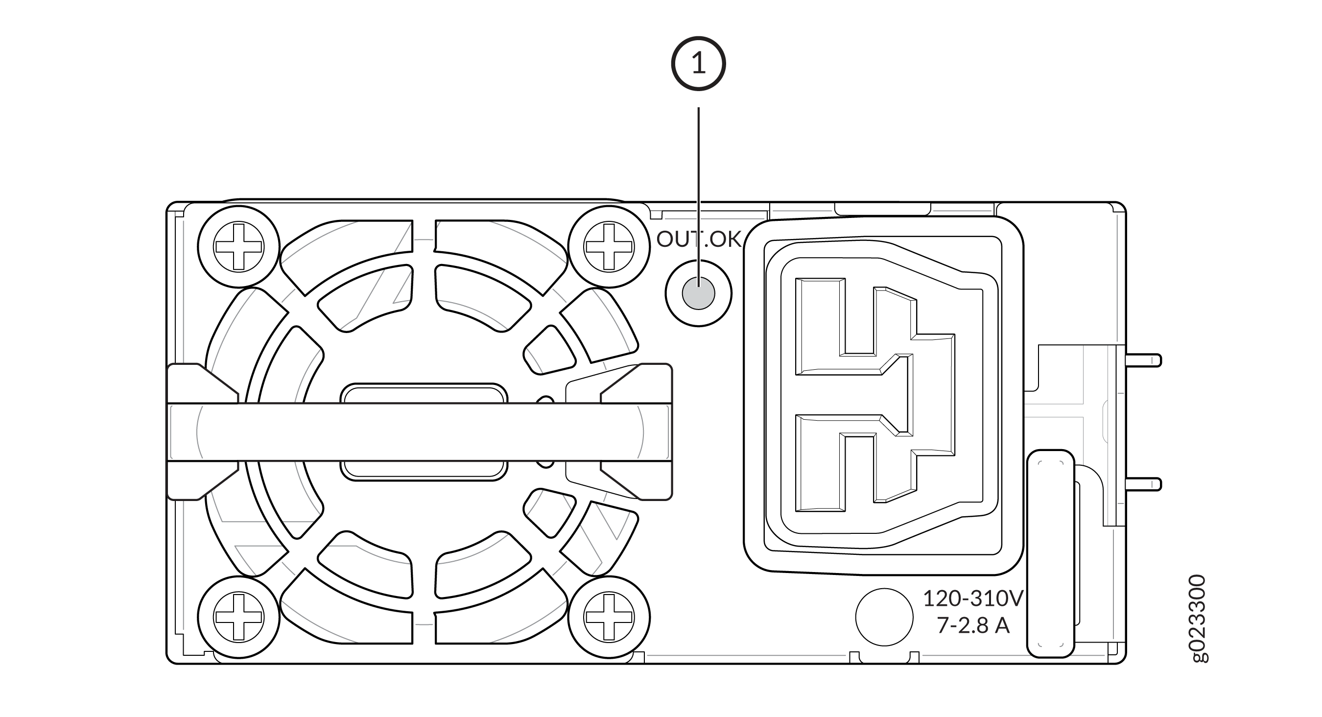
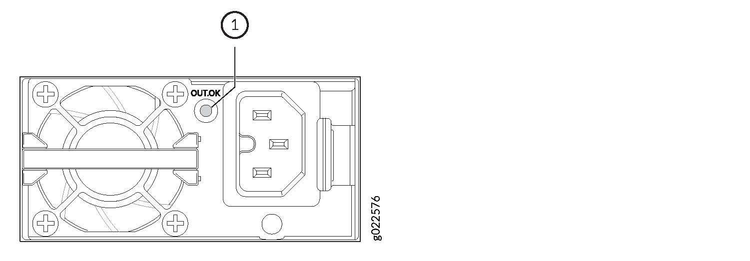
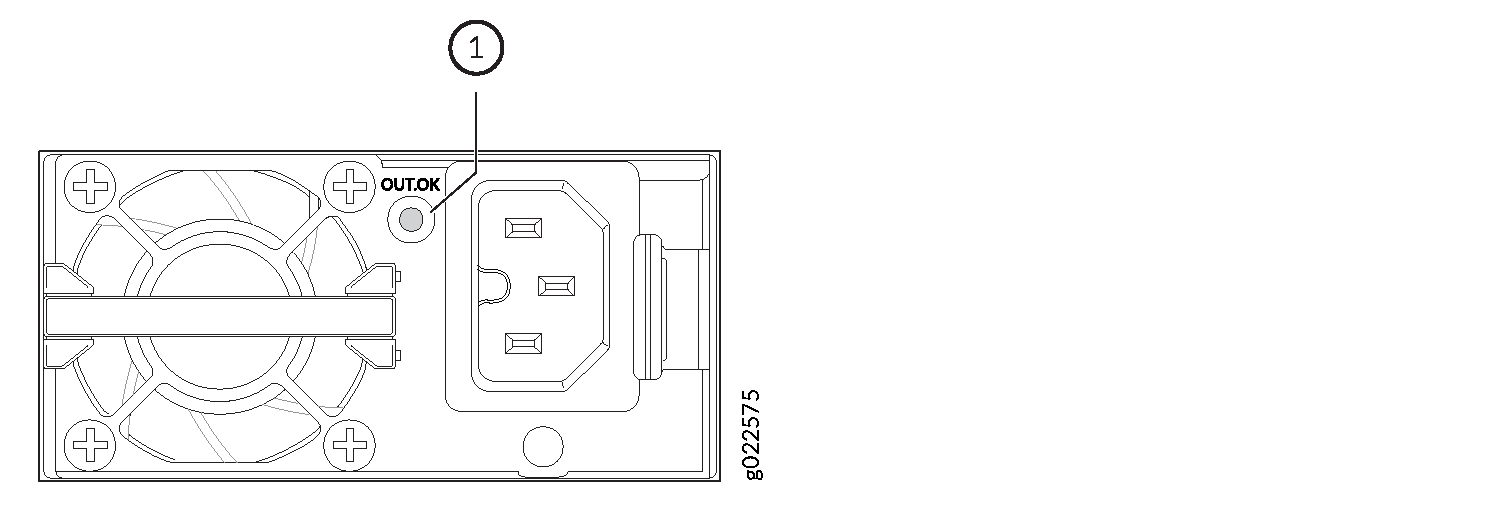
Power Supply LEDs in EX4400 Switches
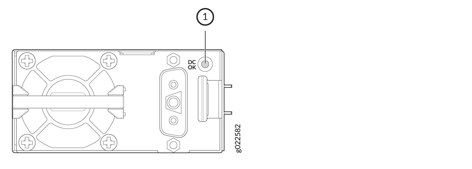
The power supplies for EX4400 switches have one LED that indicates its state.
-
Figure 8 shows the LED on the 550-W AC power supply for EX4400 switches.
-
Figure 9 shows the LED on the 550-W VDC power supply for the EX4400-48F-S switch.
-
Figure 10 shows the LED on the 1050-W AC power supply for EX4400 switches.
-
Figure 11 shows the LED on the 1600-W AC power supply for EX4400 switches.
-
Figure 12 shows the LED on the 2000-W AC power supply for EX4400 switches.
-
Figure 14 shows the LED on the 2000-W DC power supply for EX4400 switches.
-
Figure 13 shows the LED on the 550-W DC power supply for EX4400 switches.
1 — Power supply LED |
1 — Power supply LED |
1 — Power supply LED |
1 — Power supply LED |
1 — Power supply LED |
1 — Power supply LED |
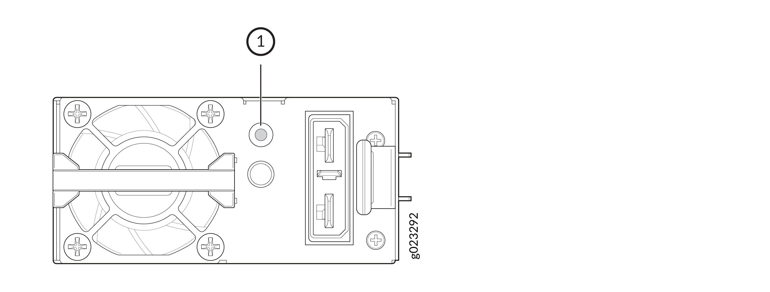
1 — Power supply LED |
Table 37 describes the power supply LED.
|
Color |
State |
Description |
|---|---|---|
|
Green |
On steadily |
The power supply is receiving input and is providing proper output to the switch. |
|
Blinking |
The fan in the power supply has failed or there is an internal communication failure in the power supply; you must replace it. |
|
|
Unlit |
Indicates one of the following:
|
- EX4400 AC Power Supply Ratings and PoE Budget in Watts
- EX4400 DC Power Supply Ratings and PoE Budget in Watts
EX4400 AC Power Supply Ratings and PoE Budget in Watts
|
Model |
Power Supply Ratings |
PoE Budget |
|
|---|---|---|---|
|
220 V (1 PSU / 2 PSU) |
110 V (1 PSU / 2 PSU) |
||
|
EX4400-48XP |
2000 W AC |
1650 W/3600 W |
724 W/ 1748 W |
|
EX4400-48P |
1600 W AC |
1310 W / 2200 W |
773 W/ 1796 W |
|
EX4400-24P |
1050 W AC |
783 W / 1806 W |
783 W/ 1806 W |
|
EX4400-24P-S |
1600 W AC |
1320 W/ 2160 W |
783 W/ 1806 W |
|
EX4400-24MP |
1050 W AC |
753 W/ 1776 W |
753 W/ 1776 W |
|
EX4400-24MP-S |
1600 W AC |
1290 W / 2160 W |
753 W/ 1776 W |
|
EX4400-48MXP |
2000 W AC |
1650 W/ 3600 W |
724 W/ 1748 W |
|
EX4400-48MP |
1600 W AC |
1260 W/ 2200 W |
723 W/ 1746 W |
EX4400-24P, EX4400-24MP, EX4400-48P, and EX4400-48MP are not supported with 2000 W AC PSU.
EX4400 DC Power Supply Ratings and PoE Budget in Watts
|
Model |
Power Supply Rating |
PoE Budget |
|---|---|---|
|
48-60 V (1 PSU / 2 PSU) |
||
|
EX4400-48XP-S |
2000 W DC |
1650 W / 3600 W |
|
EX4400-48P-S |
2000 W DC |
1700 W / 2200 W |
|
EX4400-24P-S |
2000 W DC |
1710 W / 2160 W |
|
EX4400-24MP-S |
2000 W DC |
1680 W / 2160 W |
|
EX4400-48MXP-S |
2000 W DC |
1600 W / 3600 W |
|
EX4400-48MP-S |
2000 W DC |
1650 W / 2200 W |