Cooling System and Airflow in an EX4400 Switch
The cooling system in an EX4400 switch consists of two fan modules for the chassis and a single built-in fan in each power supply. The airflow direction depends on the fan modules and power supplies installed in the switch. You can order an EX4400 switch that supports front-to-back (air enters through the front panel of the switch) or back-to-front airflow (air enters through the rear panel of the switch).
Fan Modules
The fan modules are hot-removable and hot-insertable field-replaceable units (FRUs) installed in the rear panel of the switch: You can remove and replace them without powering off the switch or disrupting switch functions.
We ship EX4400 switches with two fan modules (1+1 redundancy) preinstalled in the rear panel of the switch. The fan module slots are numbered 0 and 1, and each slot has a fan icon next to it.
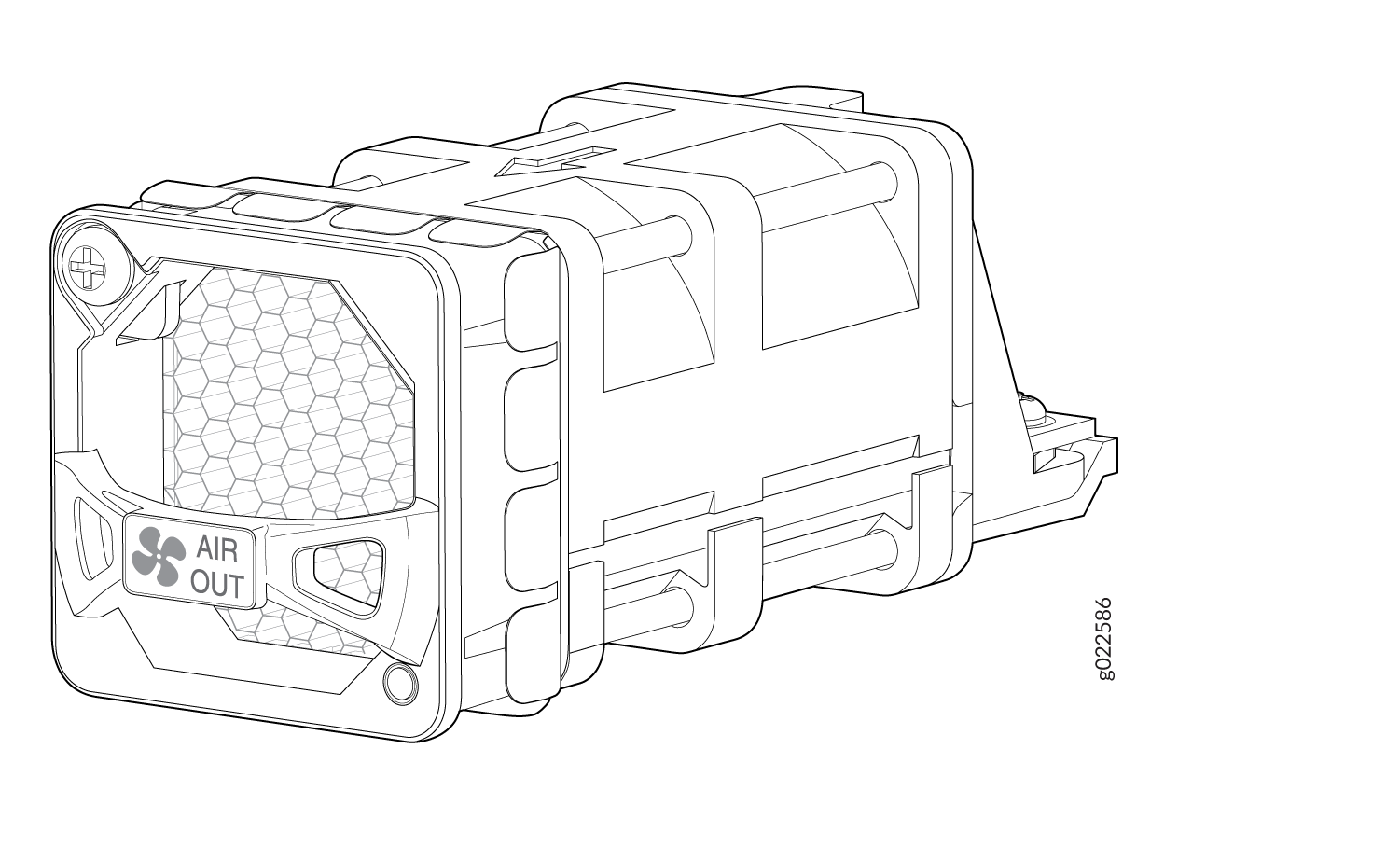
The fan modules are available in two models that have different airflow directions:
-
Front-to-back (cold air enters through the vents on the front panel of the switch and hot air exhausts through the vents on the rear panel), indicated by the AIR OUT label and the Juniper Gold handle.
-
Back-to-front (cold air enters through the vents on the rear panel of the switch and hot air exhausts through the vents on the front panel), indicated by the AIR IN label and the Juniper Azure Blue handle.
Figure 1 shows the fan module used in an EX4400 switch.
You must install all the fan modules and they must be operational for optimal functioning of the switch.
Leave at least 6 in. (15.2 cm) clearance in front and 6 in. (15.2 cm) behind the chassis for airflow.
If the switch is operational while you are replacing fan modules, you must remove only one fan module at a time. The switch continues to operate for 60 seconds without thermal shutdown while you are replacing a fan module.
Do not mix:
-
Fan modules with different airflow directions in the same chassis.
-
Power supplies with different airflow directions in the same chassis.
-
Power supplies and fan modules with different airflow directions in the same chassis.
If you install power supplies or fan modules with different airflow directions, Junos OS raises an alarm.
Under normal operating conditions, the fan modules operate at a moderate speed. Temperature sensors in the chassis monitor the temperature within the chassis.
If a fan module fails or if the ambient temperature inside the chassis rises above the acceptable range, Junos OS raises an alarm. If the temperature inside the chassis rises above the threshold temperature, the system shuts down automatically.
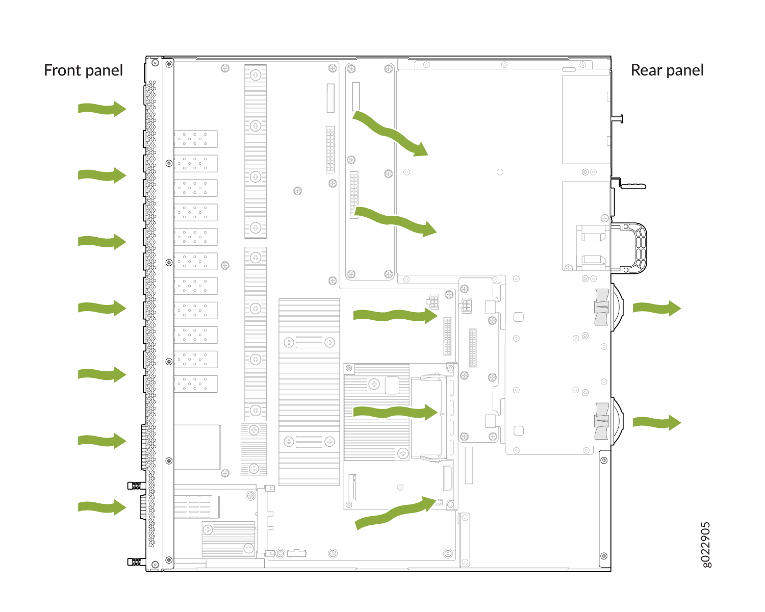
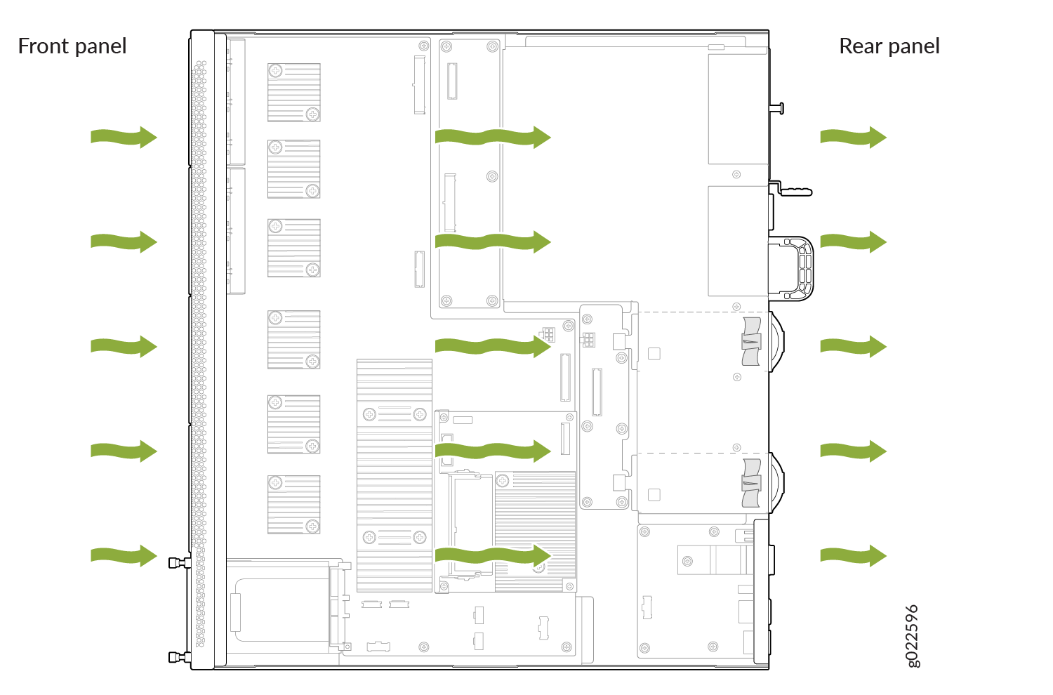
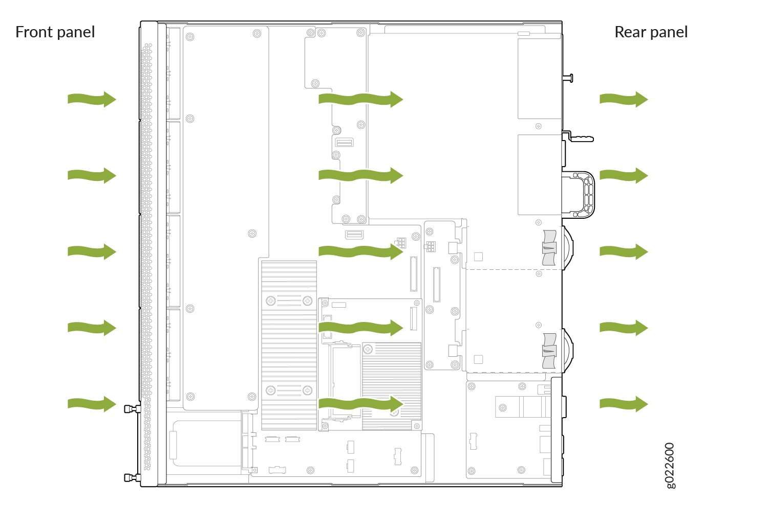
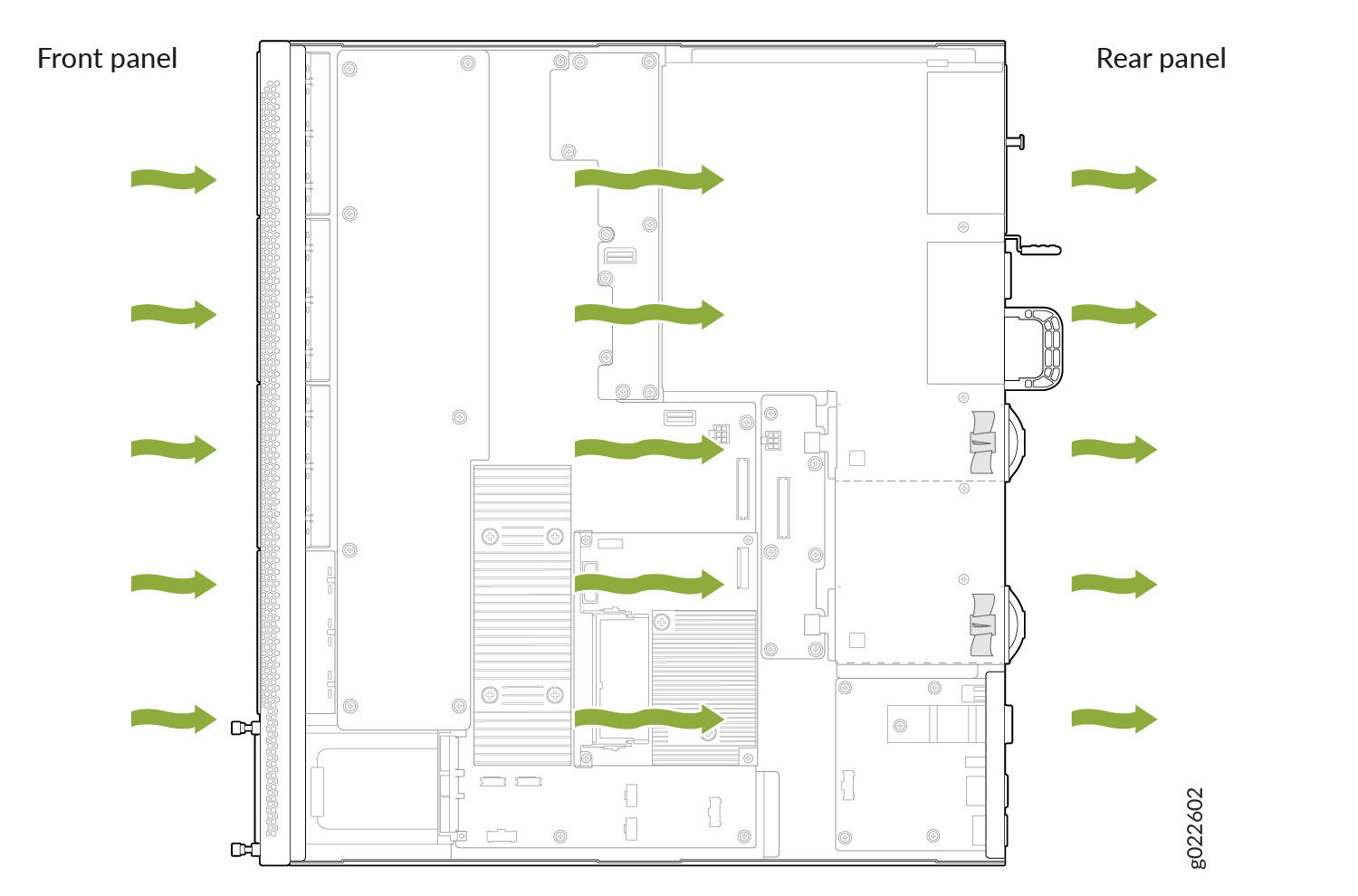
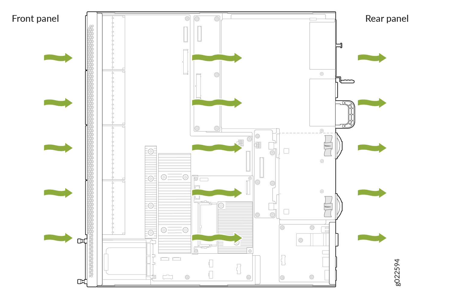
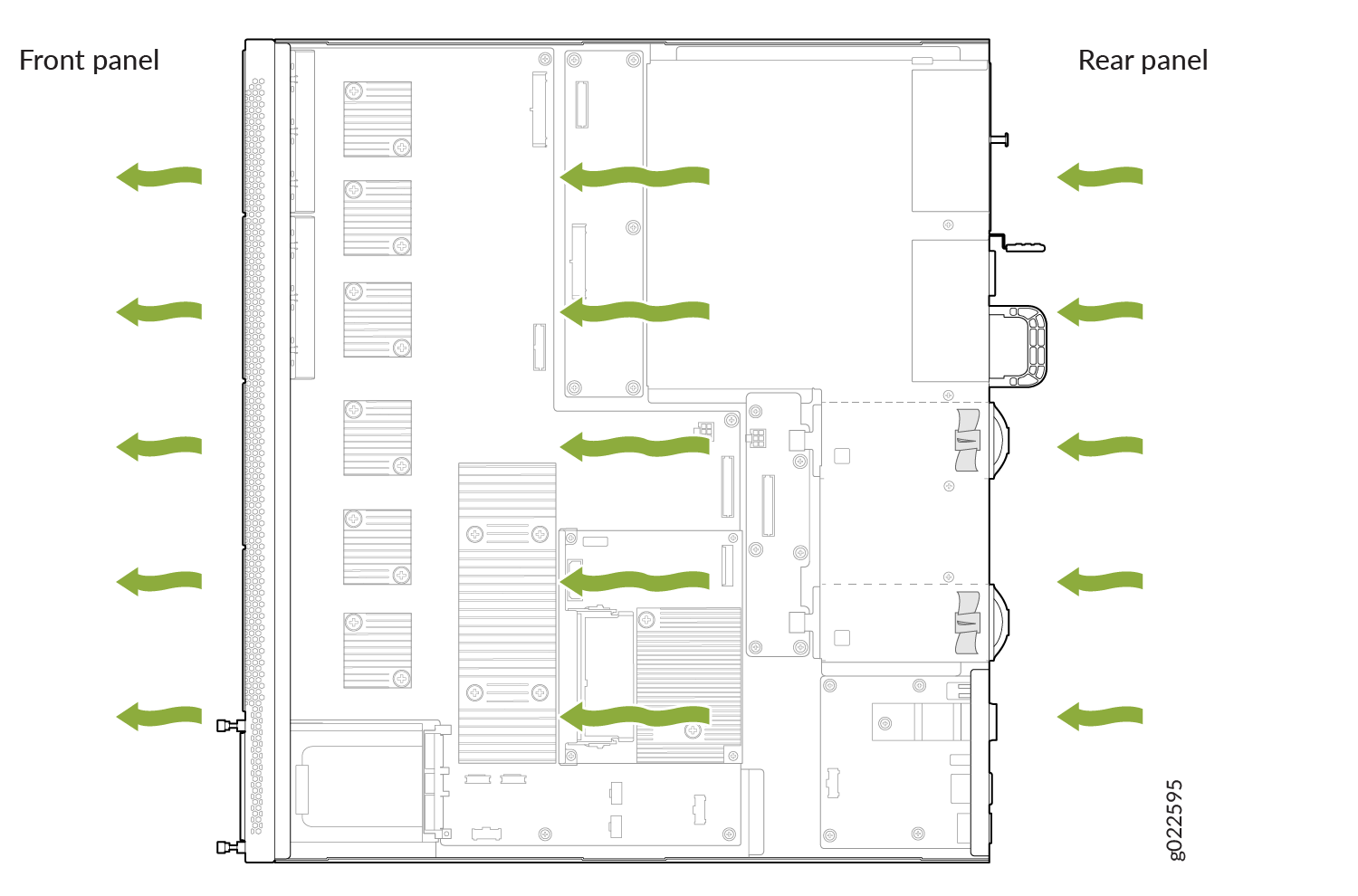
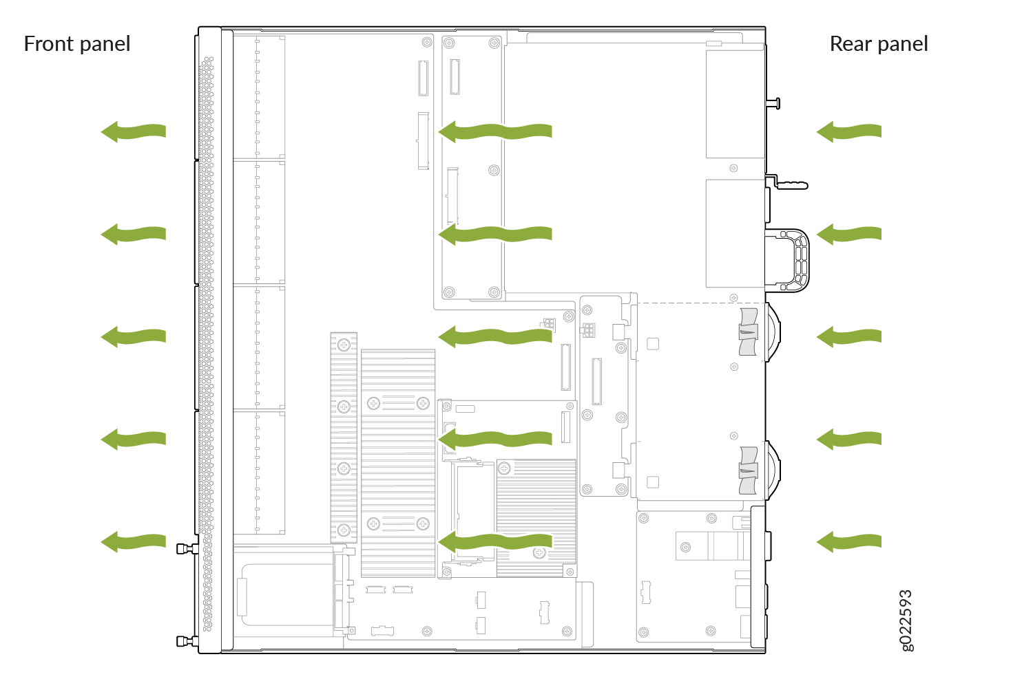
EX4400 Switches with Front-to-Back Airflow
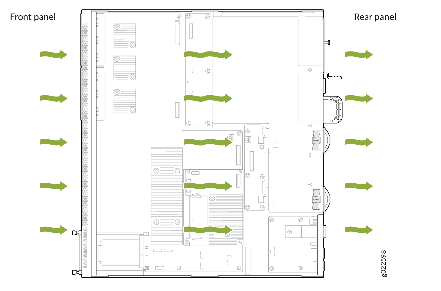
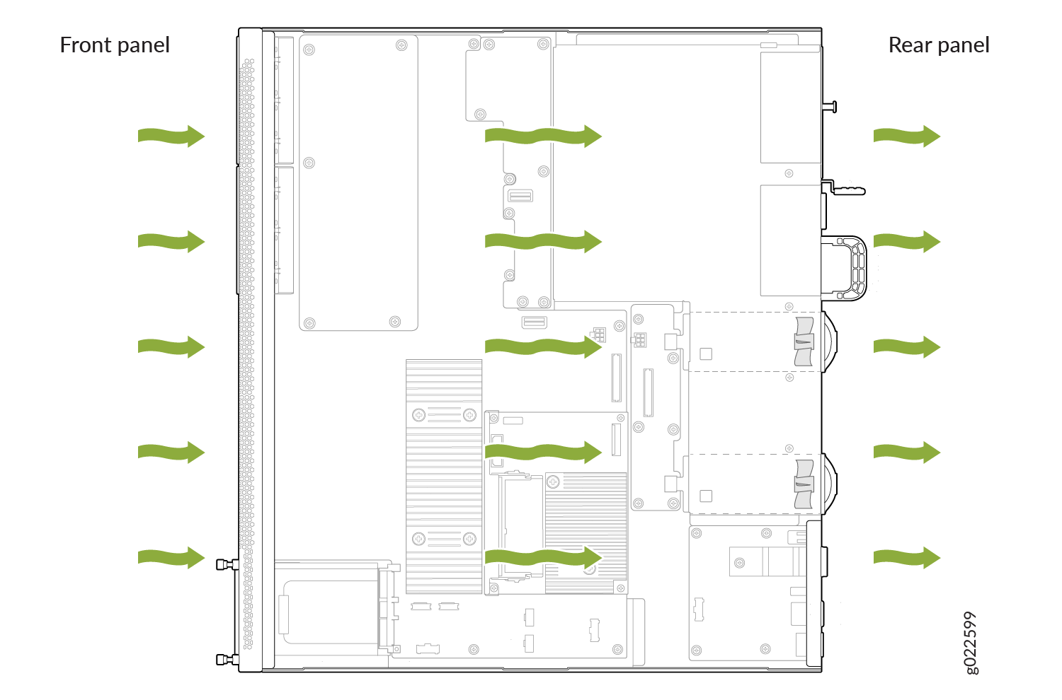
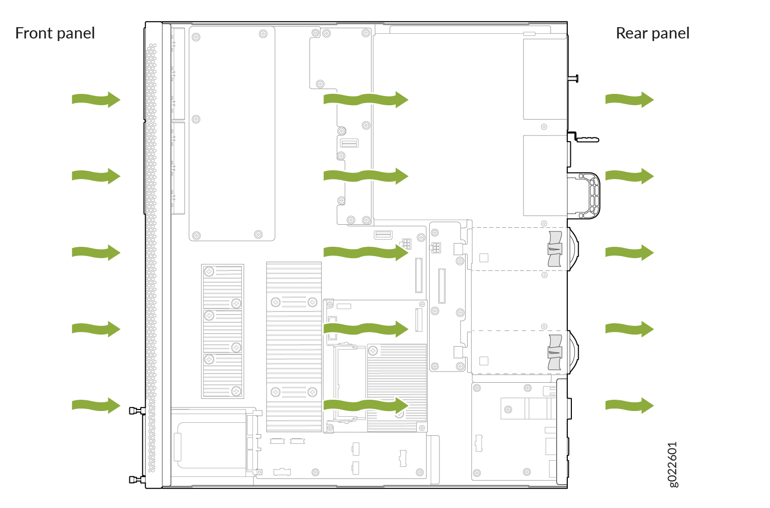
In the EX4400 switch models that have front-to-back airflow, cold air enters the chassis through the vents on the front panel and hot air exhausts the chassis through the vents on the rear panel.
-
Figure 2 shows the front-to-back airflow through an EX4400-24T switch.
-
Figure 3 shows the front-to-back airflow through an EX4400-24P switch.
-
Figure 4 shows the front-to-back airflow through an EX4400-24MP switch.
-
Figure 5 shows the front-to-back airflow through an EX4400-24X switch.
-
Figure 6 shows the front-to-back airflow through an EX4400-48T switch.
-
Figure 7 shows the front-to-back airflow through an EX4400-48P switch.
-
Figure 8 shows the front-to-back airflow through an EX4400-48XP switch.
-
Figure 9 shows the front-to-back airflow through an EX4400-48MP switch.
-
Figure 11 shows the front-to-back airflow through an EX4400-48F switch.
-
Figure 10 shows the front-to-back airflow through an EX4400-48MXP switch.
Mixing components with different airflow directions in the same chassis hampers the performance of the cooling system of the switch and leads to overheating of the chassis.
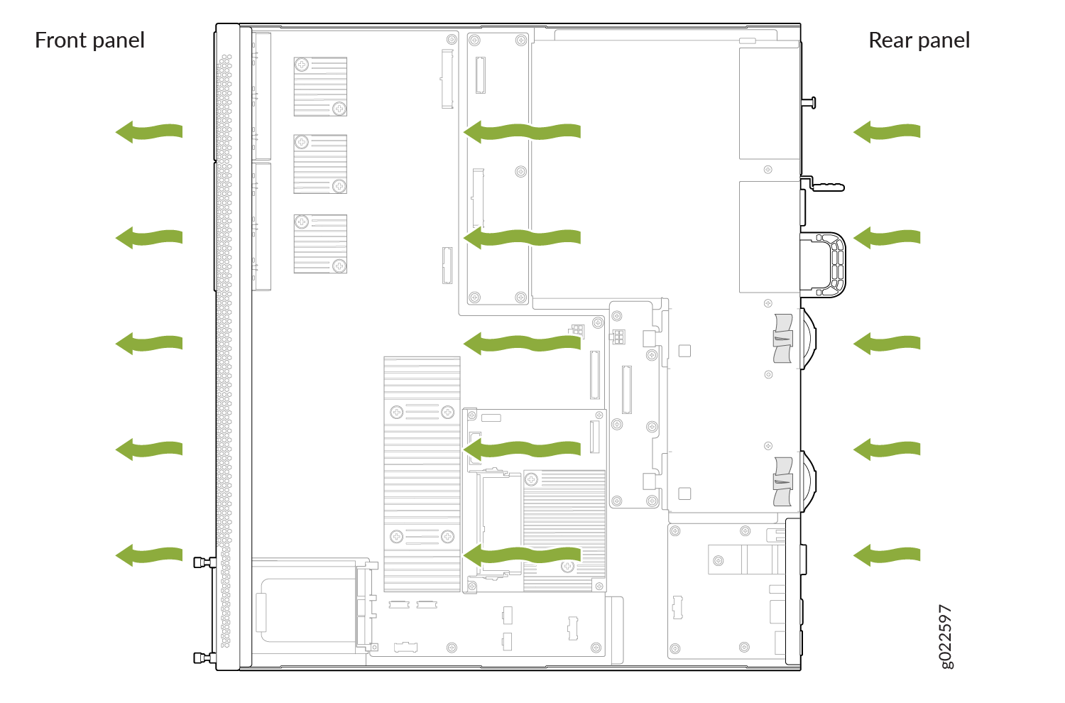
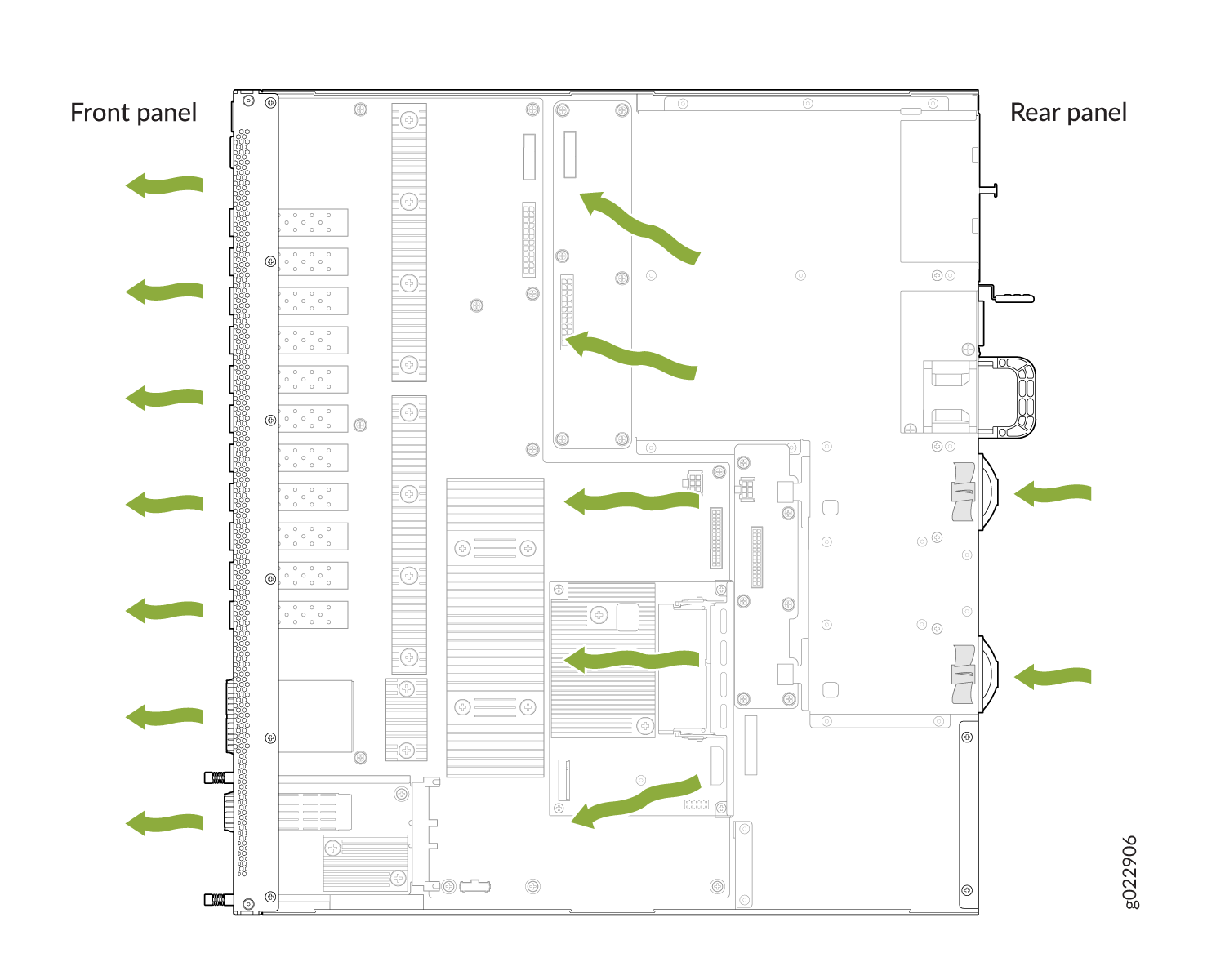
EX4400 Switches with Back-to-Front Airflow
In the EX4400 switch models that have back-to-front airflow, cold air enters the chassis through the vents on the rear panel of the switch and hot air exhausts the chassis through the vents on the front panel.
-
Figure 12 shows the back-to-front airflow through an EX4400-24T switch.
-
Figure 13 shows the back-to-front airflow through an EX4400-24X switch.
-
Figure 14 shows the back-to-front airflow through an EX4400-48T switch.
-
Figure 15 shows the back-to-front airflow through an EX4400-48F switch.
Mixing components with different airflow directions in the same chassis hampers the performance of the cooling system of the switch and leads to overheating of the chassis.
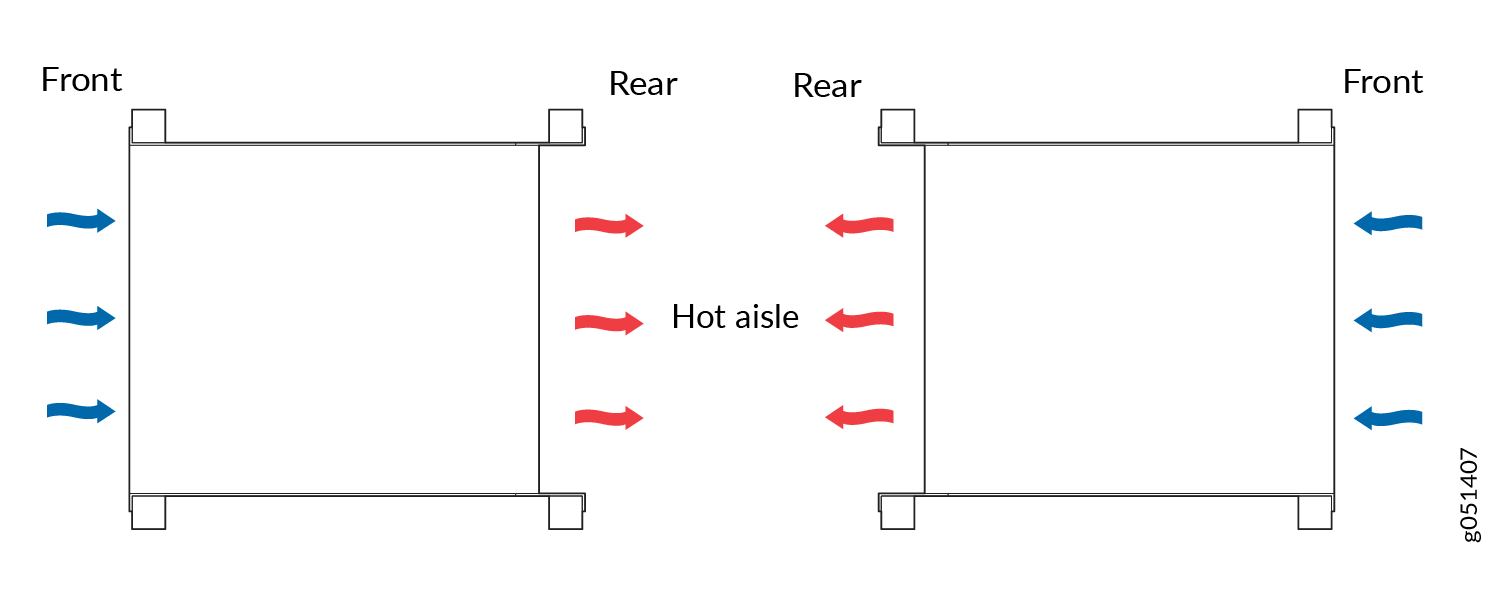
How to Position the Switch
Position the switch with front-to-back airflow in such a manner that the AIR OUT labels on the fan modules and power supplies are next to the hot aisle (see Figure 16).
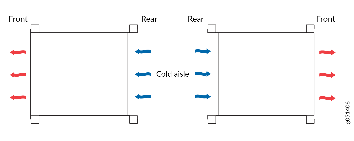
Position the switch with back-to-front airflow in such a manner that the AIR IN labels on the fan modules and power supplies are next to the cold aisle (see Figure 17).
Fan Module Status
Each fan module has a status LED on it that indicates the status of the fan module (see Figure 18).
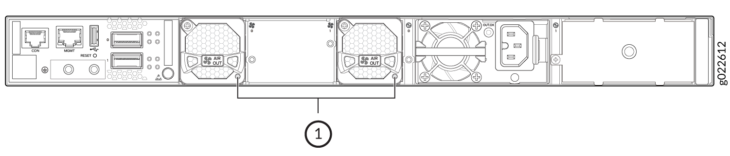
Table 1 describes the LED.
|
State |
Description |
|---|---|
|
Lit green |
The fan module is functioning normally. |
|
Unlit |
Indicates one of the following:
|
Heat Dissipation Values
The following table enumerates the heat dissipation values for the EX4400 switches.
|
Switch Model |
PSU Type |
PSU (W) |
Dissipation Values (BTU/hr) |
||||
|---|---|---|---|---|---|---|---|
|
Idle 0% Traffic |
10% Traffic |
30% Traffic |
50% Traffic |
100% Max |
|||
|
EX4400-24MP |
AC |
1050 |
467.17 |
467.17 |
470.58 |
473.99 |
477.4 |
|
EX4400-24MP with PoE |
AC |
1050 |
6,339.19 |
6,339.19 |
6,342.6 |
6,342.6 |
6,346.01 |
|
EX4400-24MP-S |
DC |
2000 |
306.9 |
375.1 |
388.74 |
405.7 |
419.4 |
|
EX4400-24MP-S with PoE |
DC |
2000 |
7672.5 |
7,740.7 |
7,754.34 |
7,771.39 |
7,785.03 |
|
EX4400-24P |
AC |
1050 |
296.67 |
385.33 |
402.38 |
416.02 |
433.07 |
|
EX4400-24P with PoE |
AC |
1050 |
5,445.77 |
5,445.77 |
5,452.59 |
5,452.59 |
5,459.41 |
|
EX4400-24P-S |
DC |
2000 |
296.67 |
385.33 |
402.38 |
416.02 |
433.07 |
|
EX4400-24P-S with PoE |
DC |
2000 |
7,662.27 |
7,750.93 |
7,767.98 |
7,781.62 |
7,798.67 |
|
EX4400-24T |
AC |
550 |
300.08 |
296.67 |
306.9 |
310.31 |
313.72 |
|
EX4400-24T |
DC |
550 |
320.54 |
323.95 |
327.36 |
330.77 |
337.59 |
|
EX4400-24X |
AC |
550 |
422.84 |
433.07 |
443.3 |
453.53 |
470.58 |
|
EX4400-24X |
DC |
550 |
463.76 |
467.17 |
473.99 |
480.81 |
497.86 |
|
EX4400-48MP |
AC |
1600 |
620.62 |
620.62 |
624.03 |
624.03 |
630.85 |
|
EX4400-48MP with PoE |
AC |
1600 |
8,470.44 |
8,470.44 |
8,470.44 |
8,473.85 |
8,477.26 |
|
EX4400-48MP-S |
DC |
2000 |
364.87 |
579.7 |
600.16 |
613.8 |
630.85 |
|
EX4400-48MP-S with PoE |
DC |
2000 |
7,866.87 |
8,081.7 |
8,102.16 |
8,115.8 |
8,132.85 |
|
EX4400-48P |
AC |
1600 |
456.94 |
456.94 |
460.35 |
463.76 |
470.58 |
|
EX4400-48P with PoE |
AC |
1600 |
6,693.83 |
6,693.83 |
6,697.24 |
6,704.06 |
6,707.47 |
|
EX4400-48P-S |
DC |
2000 |
412.61 |
477.4 |
501.27 |
514.91 |
531.96 |
|
EX4400-48P-S with PoE |
DC |
2000 |
7,914.61 |
7,979.4 |
8,003.27 |
801.35 |
8,033.96 |
|
EX4400-48T |
DC |
550 |
344.41 |
344.41 |
347.82 |
351.23 |
361.46 |
|
EX4400-48T |
AC |
550 |
323.95 |
323.95 |
327.36 |
330.77 |
337.59 |
|
EX4400-48F |
AC |
550 |
388.74 |
392.15 |
395.56 |
402.38 |
412.61 |
|
EX4400-48F |
DC |
550 |
429.66 |
433.07 |
436.48 |
443.3 |
453.53 |
|
EX4400-48XP |
AC |
2000 |
318.835 |
535.029 |
555.148 |
565.037 |
575.267 |
|
EX4400-48XP with PoE |
AC |
2000 |
12,937.54 |
12,951.18 |
12,964.82 |
12,978.46 |
12,998.92 |
|
EX4400-48XP-S |
DC |
2000 |
405.79 |
409.2 |
419.43 |
439.89 |
450.12 |
|
EX4400-48XP-S with PoE |
DC |
2000 |
12,681.79 |
12,685.2 |
12,695.43 |
12,715.89 |
12,726.12 |
|
EX4400-48MXP |
AC |
2000 |
357.368 |
358.05 |
367.257 |
387.717 |
398.288 |
|
EX4400-48MXP with PoE |
AC |
2000 |
12,753.4 |
12,794.32 |
12,814.78 |
12,835.24 |
12,876.16 |
|
EX4400-48MXP-S |
DC |
2000 |
388.74 |
603.57 |
624.03 |
634.26 |
647.9 |
|
EX4400-48MXP-S with PoE |
DC |
2000 |
12,664.74 |
12,879.57 |
12,900.03 |
12,910.26 |
12,920.49 |