SRX 시리즈 방화벽을 연결하여 섀시 클러스터 생성
SRX 시리즈 섀시 클러스터는 동일한 유형의 이더넷 연결 한 쌍을 사용하여 두 개의 동일한 클러스터 지원 SRX 시리즈 방화벽을 물리적으로 함께 연결하여 생성됩니다. 연결은 두 디바이스 간의 제어 링크 및 패브릭(데이터) 링크 모두에 대해 이루어집니다.
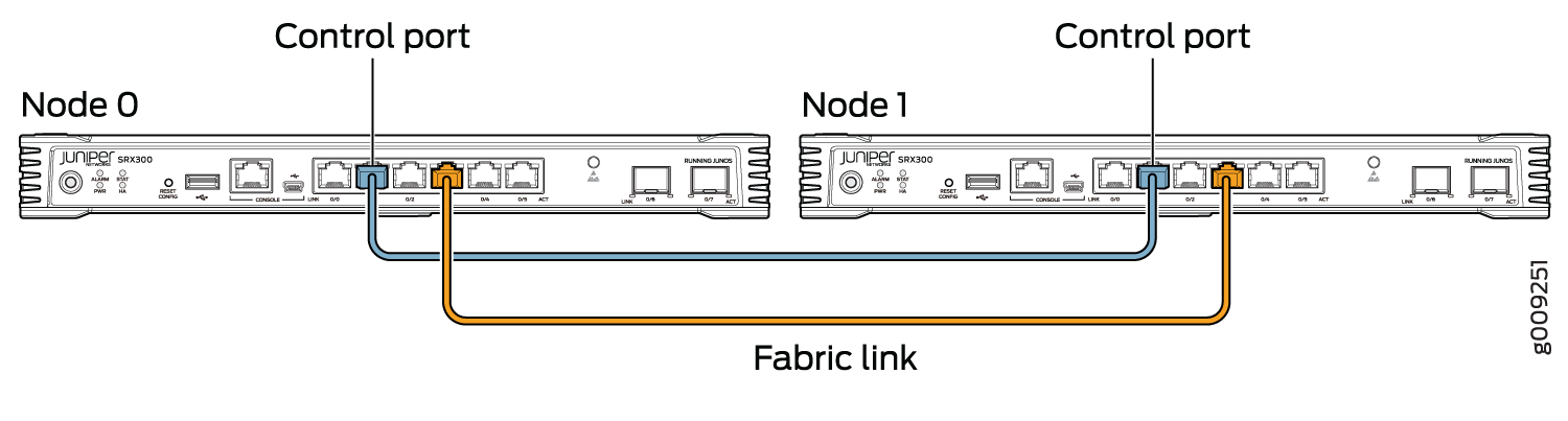
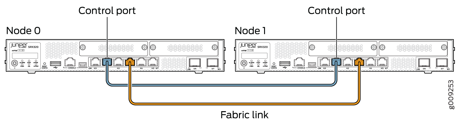
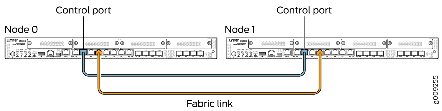
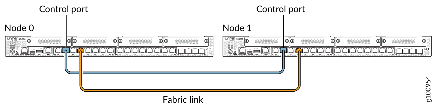
섀시 클러스터의 제어 링크는 특정 포트를 사용하여 만들어집니다.
인터페이스 값은 클러스터 오프셋 값에 따라 변경됩니다. 클러스터 인덱스에 따라 인터페이스 이름은 type-fpc/pic/port로 지정됩니다. 예를 들어, ge-1/0/1 입니다. 여기서 1은 클러스터 인덱스이고 FPC 번호입니다. 다음 SRX 시리즈 방화벽에서 제어 링크를 형성하려면 다음 포트를 사용해야 합니다.
-
SRX300 디바이스의 경우 노드 0의 ge-0/0/1을 노드 1의 ge-1/0/1에 연결합니다.
-
SRX320 디바이스의 경우 노드 0의 ge-0/0/1을 노드 1의 ge-3/0/1에 연결합니다.
-
SRX340, SRX345, SRX380 디바이스의 경우 노드 0의 ge-0/0/1을 노드 1의 ge-5/0/1에 연결합니다.
-
SRX1500 디바이스의 경우 노드 0의 HA 제어 포트를 노드 1의 HA 제어 포트에 연결합니다.
-
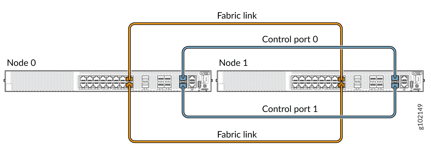
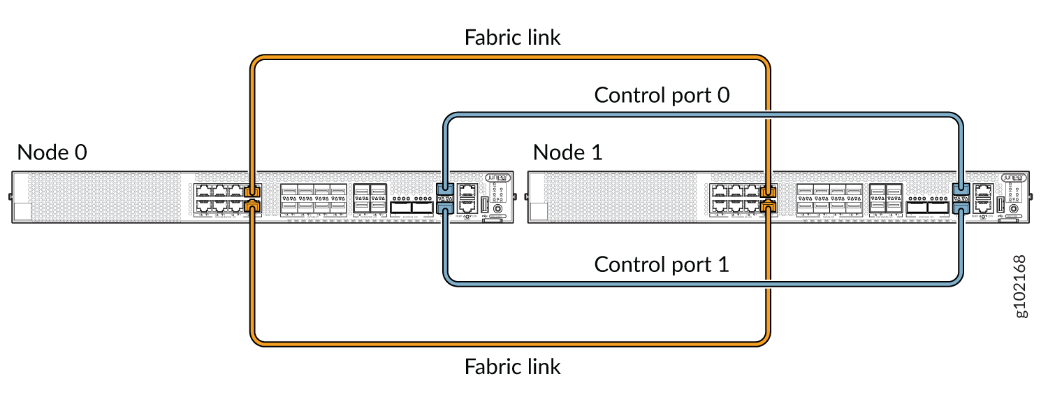
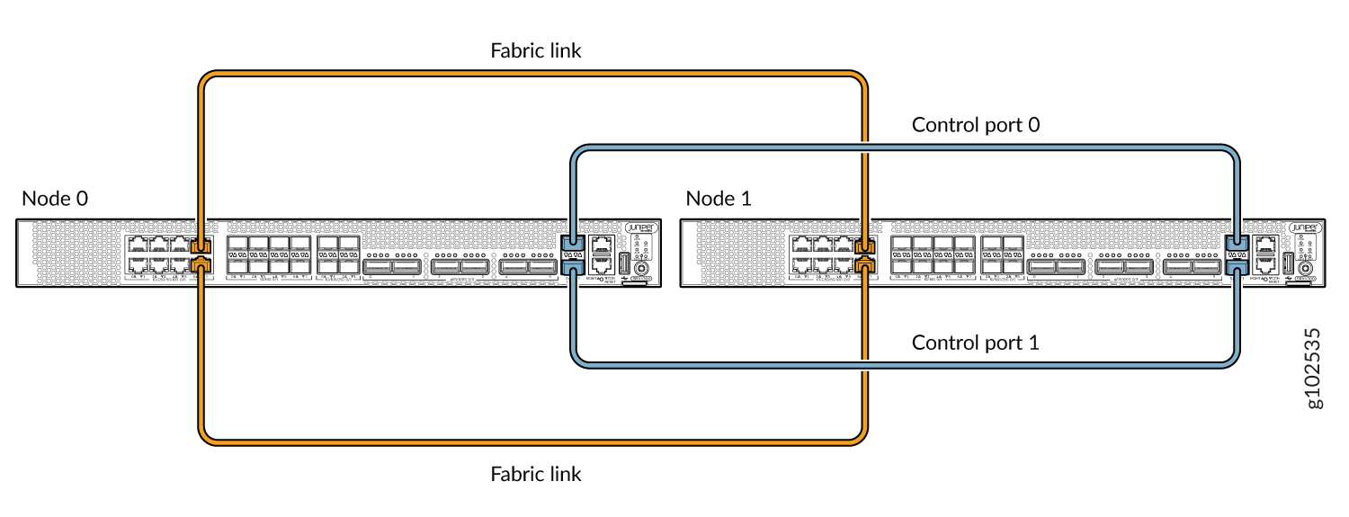
SRX1600, SRX2300, SRX4120 및 SRX4300 디바이스 이중 제어 링크 구성의 경우 노드 0의 HA 제어 포트 0을 노드 1의 HA 제어 포트 0에 연결하고 노드 0의 HA 제어 포트 1을 노드 1의 제어 포트 1에 연결합니다.
패브릭 링크 설정 방법:
-
SRX300 및 SRX320 디바이스의 경우 ge-0/0/0 및 ge-0/0/1을 제외한 인터페이스를 연결합니다.
-
SRX340, SRX345 및 SRX380 디바이스의 경우 fxp0 및 ge-0/0/1을 제외한 인터페이스를 연결합니다.
그림 2, 그림 3, 그림 4 및 그림 6은 패브릭 링크와 제어 링크가 연결된 SRX 시리즈 방화벽 쌍을 보여줍니다.
 에서 SRX300 디바이스 연결
 에서 SRX320 디바이스 연결
 에서 SRX340 디바이스 연결
 에서 SRX345 디바이스 연결
 에서 SRX380 디바이스 연결
 에서 SRX1500 디바이스 연결
 에서 SRX1600 디바이스 연결
SRX1500, SRX1600, SRX2300, SRX4120 및 SRX4300 디바이스의 경우, 제어 링크 역할을 하는 연결은 각 디바이스에 내장된 제어 포트 사이에 있어야 합니다.
클러스터에 있는 두 디바이스 간에 두 개의 제어 링크(SRX4600, SRX5600 및 SRX5800)와 두 개의 패브릭 링크를 연결하여 제어 링크 및 패브릭 링크 실패 가능성을 줄일 수 있습니다. 섀시 클러스터 이중 제어 링크 이해 및 섀시 클러스터 이중 패브릭 링크 이해를 참조하십시오.
그림 12, 그림 9 및 그림 10은 패브릭 링크와 제어 링크가 연결된 SRX 시리즈 방화벽 쌍을 보여줍니다.
 에서 SRX2300 및 SRX4120 디바이스 연결
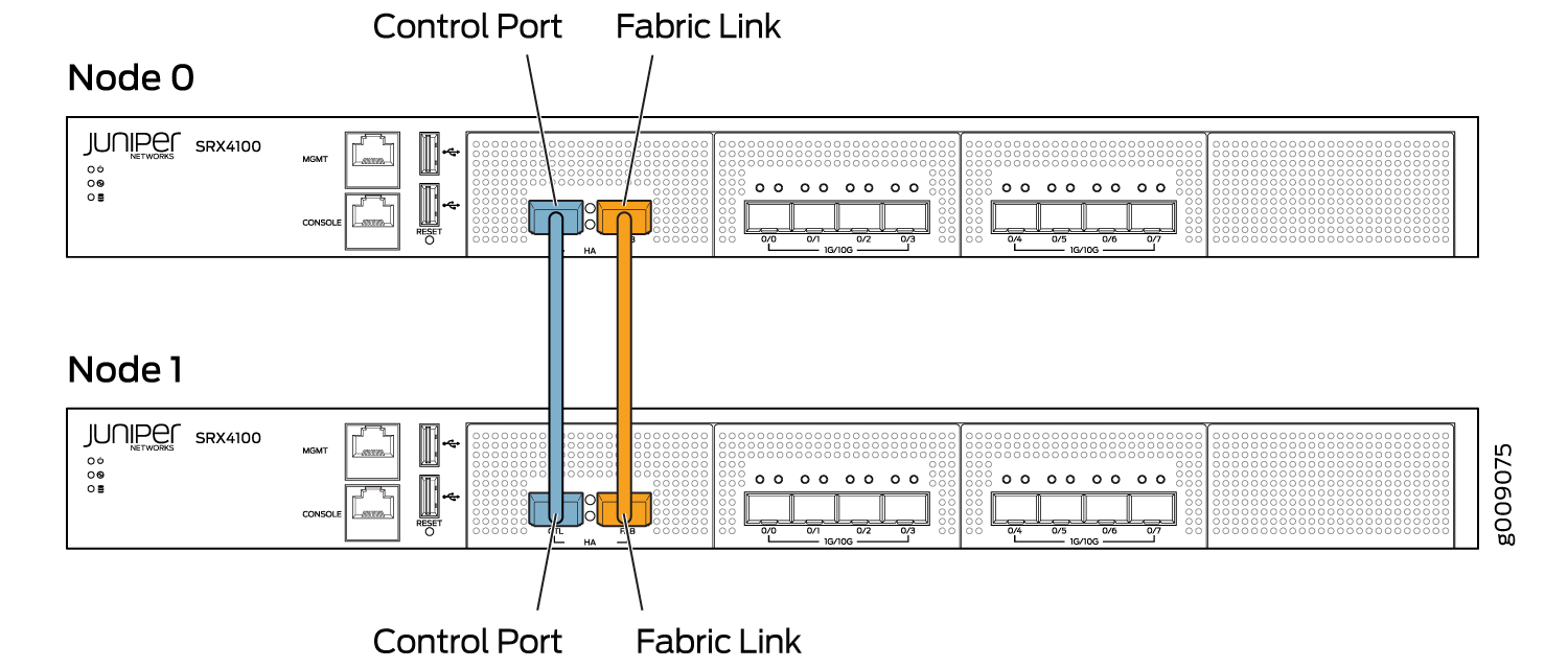 에서 SRX4100 디바이스 연결
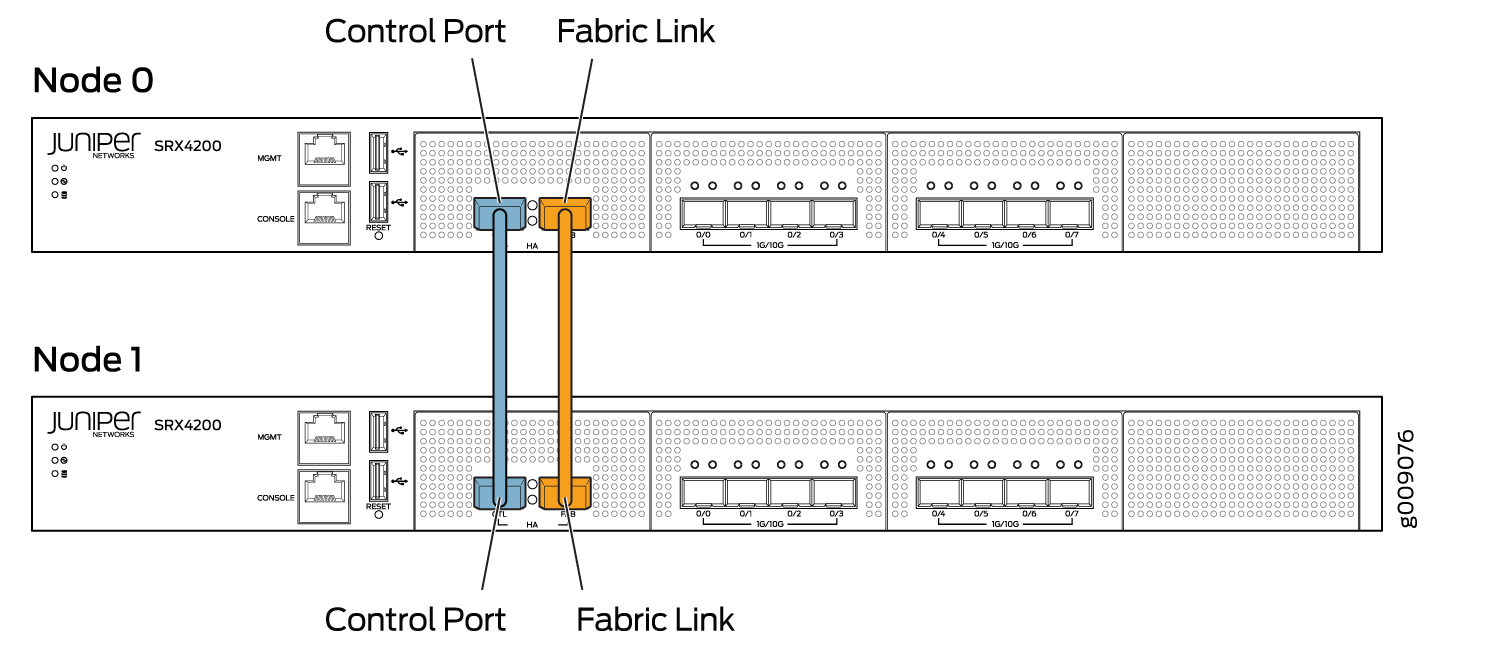 에서 SRX4200 디바이스 연결
 에서 SRX4300 디바이스 연결
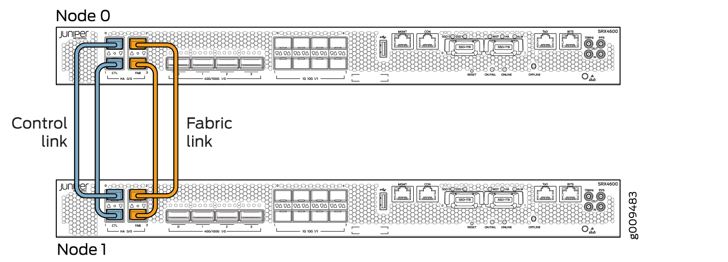 에서 SRX4600 디바이스 연결
그림 13, 그림 14 및 그림 15는 패브릭 링크와 제어 링크가 연결된 SRX 시리즈 방화벽 쌍을 보여줍니다.
SPC(Service Processing Card)에는 섀시 클러스터의 제어 링크를 연결하기 위한 2개의 전용 포트(HA0 및 HA1)가 있습니다.
패브릭 포트는 모든 IOC 카드에서 사용할 수 있는 수익 포트입니다. 패브릭 링크는 SRX5000 라인 모두에서 동일한 슬롯과 포트에 연결됩니다.
SRX5000 라인 디바이스에는 내장 포트가 없으므로 이러한 게이트웨이의 제어 링크는 SRX5400의 경우 슬롯 번호 오프셋이 3, SRX5600 디바이스의 경우 6, SRX5800 디바이스의 경우 12의 슬롯 번호 오프셋을 가진 SPC의 제어 포트여야 합니다.
그림 13은 각각 제어 링크로 연결된 단일 SPC 카드가 있는 SRX5800 디바이스 쌍을 보여줍니다. 패브릭 링크는 IOC 카드를 사용하여 연결됩니다. 이중 제어 링크는 각 노드에서 하나의 SPC 카드를 사용하여 설정됩니다. 중복을 위해 각 노드에 있는 두 개의 서로 다른 SPC 카드에서 1차 및 2차 제어 포트를 분리하는 것이 좋습니다.
 에서 SRX5800 디바이스 연결
그림 14 는 두 개의 SPC3 카드를 사용하여 연결된 이중 제어 링크와 IOC 카드를 사용하여 연결된 이중 패브릭 링크를 보여줍니다.
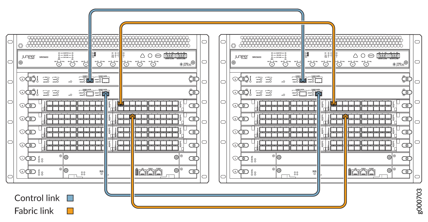 에서 SRX5600 디바이스 연결
SRX5000 라인 디바이스에서 단일 제어 링크를 연결할 때, 제어 링크 포트는 라우팅 엔진 슬롯과 일대일 매핑입니다. 라우팅 엔진이 슬롯 0에 있는 경우, 컨트롤 포트 0을 사용하여 라우팅 엔진을 연결해야 합니다.
SPC가 중앙 지점이면서 제어 포트를 호스팅하는 경우, 단일 장애 지점이 생성됩니다. 기본 노드에서 SPC가 다운되면 스플릿 브레인을 방지하기 위해 노드가 자동으로 재부팅됩니다.
 에서 SRX5400 디바이스 연결
이중 제어 링크는 슬롯 수가 제한되어 있기 때문에 SRX5400 디바이스에서 지원되지 않습니다.