シャーシ クラスタを作成するためのSRXシリーズ ファイアウォールの接続
SRXシリーズシャーシクラスターは、同じタイプのイーサネット接続のペアを使用して、クラスターがサポートする2つの同一のSRXシリーズファイアウォールを物理的に接続することによって作成されます。2つのデバイス間の制御リンクとファブリック(データ)リンクの両方に対して接続が確立されます。
シャーシクラスタ内の制御リンクは、特定のポートを使用して作成されます。
インターフェイス値は、クラスタオフセット値によって変化します。クラスタインデックスに基づいて、インターフェイスの名前はtype-fpc/pic/portとなります。例えば、ge-1/0/1 では、1 はクラスター インデックスと FPC 番号です。以下のSRXシリーズファイアウォールで制御リンクを形成するには、以下のポートを使用する必要があります。
-
SRX300デバイスの場合、ノード0のge-0/0/1をノード1のge-1/0/1に接続します。
-
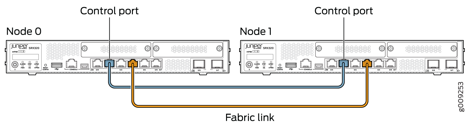
SRX320デバイスの場合、ノード0のge-0/0/1をノード1のge-3/0/1に接続します。
-
SRX340、SRX345、SRX380のデバイスでは、ノード0のge-0/0/1をノード1のge-5/0/1に接続します。
-
SRX1500 デバイスの場合は、ノード 0 の HA 制御ポートをノード 1 の HA 制御ポートに接続します。
-
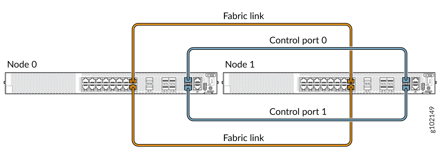
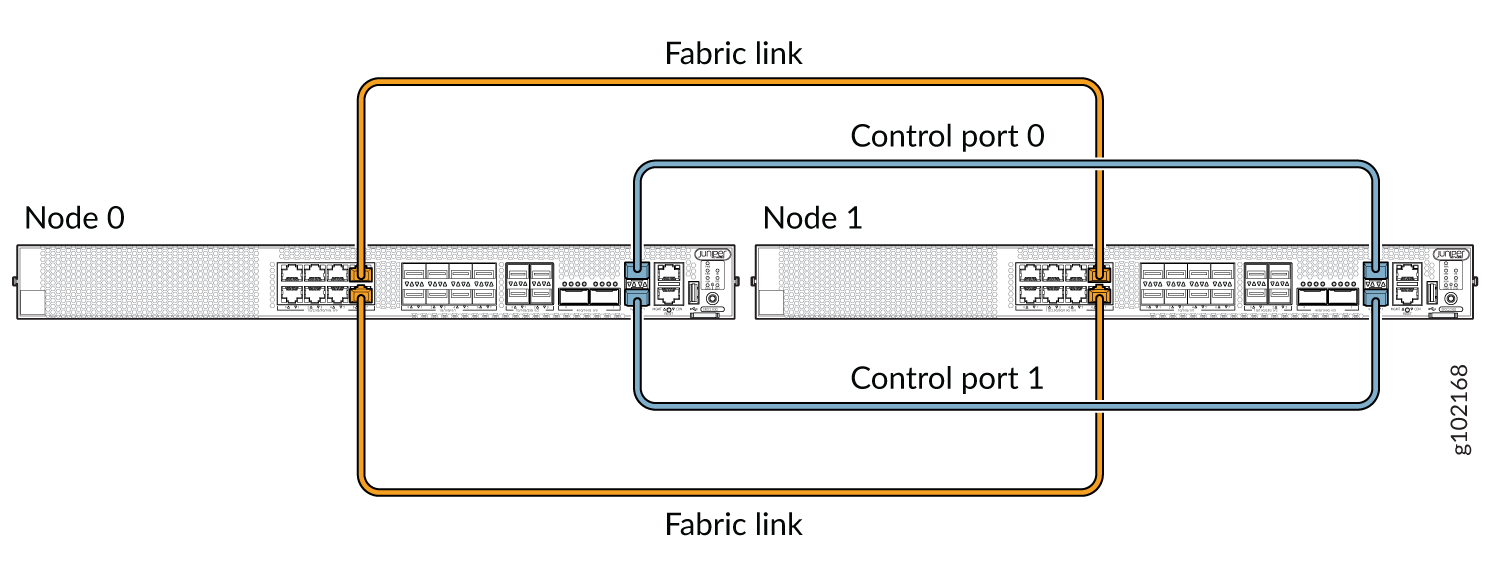
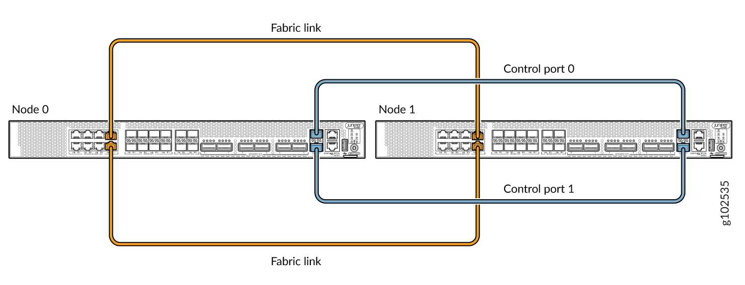
SRX1600、SRX2300、SRX4120、およびSRX4300デバイスのデュアル制御リンク構成では、ノード0のHA制御ポート0をノード1のHA制御ポート0に接続し、ノード0のHA制御ポート1をノード1の制御ポート1に接続します。
ファブリックリンクを確立するには:
-
SRX300 および SRX320 デバイスでは、ge-0/0/0 と ge-0/0/1 以外の任意のインターフェイスを接続します。
-
SRX340、SRX345、SRX380 デバイスでは、fxp0 と ge-0/0/1 以外の任意のインターフェイスを接続します。
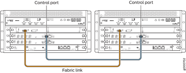
図2、図3、図4、および図6は、ファブリックリンクと制御リンクが接続されたSRXシリーズファイアウォールのペアを示しています。
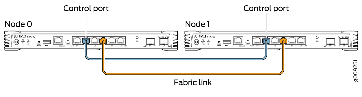 でのSRX300デバイスの接続
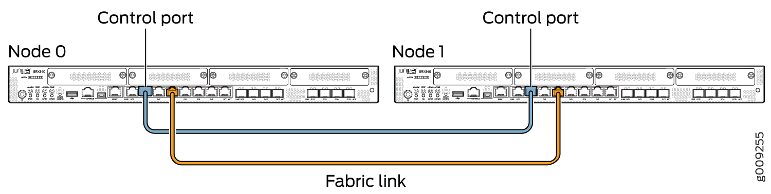 でのSRX340デバイスの接続
 でのSRX345デバイスの接続
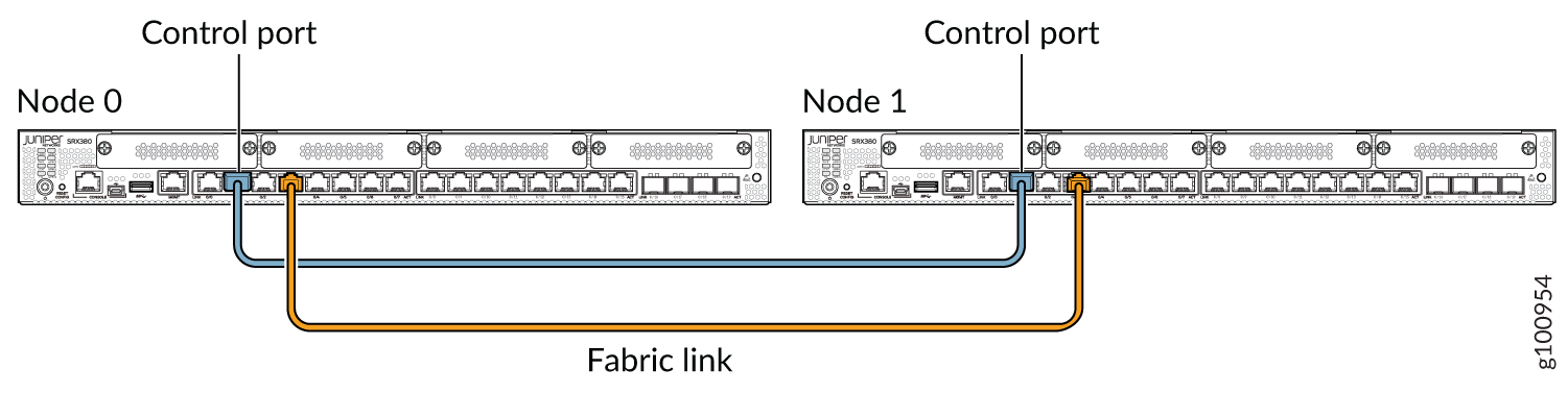 でのSRX380デバイスの接続
 でのSRX1500 デバイスの接続
 でのSRX1600 デバイスの接続
SRX1500、SRX1600、SRX2300、SRX4120、およびSRX4300デバイスの場合、制御リンクとして機能する接続は、各デバイスの組み込み制御ポート間にある必要があります。
クラスタ内の2つのデバイス間で、2つの制御リンク(SRX4600、SRX5600、SRX5800)と2つのファブリックリンクを接続して、制御リンクとファブリックリンクの障害の可能性を減らすことができます。 シャーシ クラスタ デュアル コントロール リンクについて および シャーシ クラスタ デュアル ファブリック リンクについてを参照してください。
図12、図9、図10は、ファブリックリンクと制御リンクが接続されたSRXシリーズファイアウォールのペアを示しています。
 での SRX2300 デバイスと SRX4120 デバイスの接続
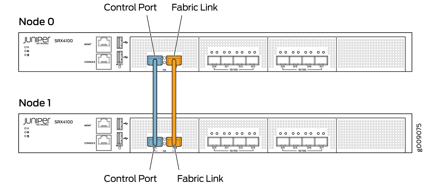 でのSRX4100 デバイスの接続
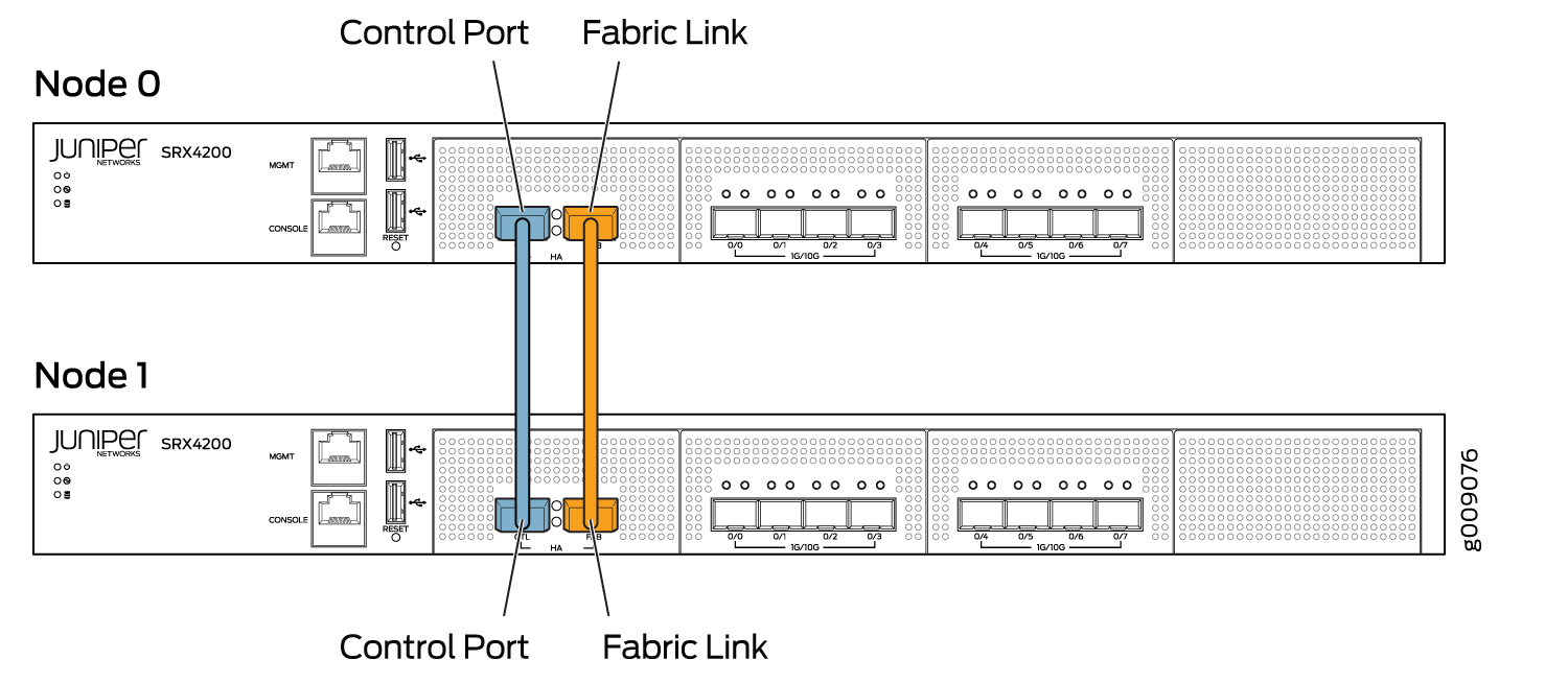 でのSRX4200 デバイスの接続
 でのSRX4300 デバイスの接続
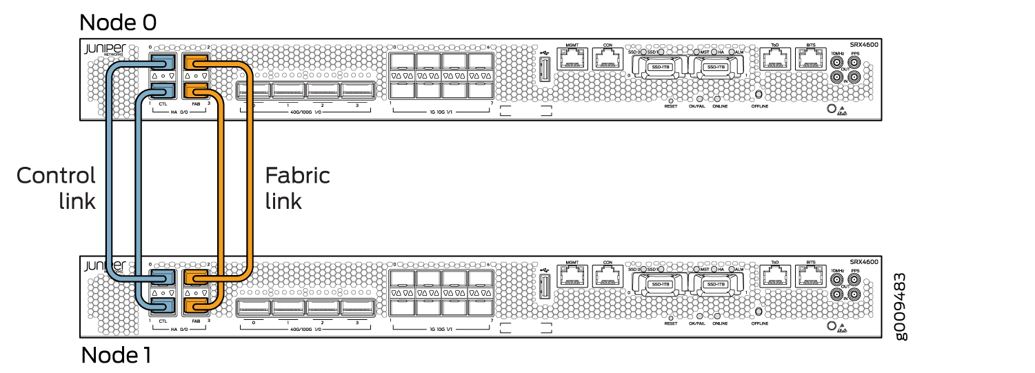 でのSRX4600 デバイスの接続
図13、図14、および図15は、ファブリックリンクと制御リンクが接続されたSRXシリーズファイアウォールのペアを示しています。
サービス処理カード(SPC)には、シャーシクラスター内の制御リンクを接続するための2つの専用ポート(HA0およびHA1)があります。
ファブリックポートは、任意のIOCカードから使用できる収益ポートです。ファブリック リンクは、両方の SRX5000シリーズ デバイスの同じスロットとポートに接続されます。
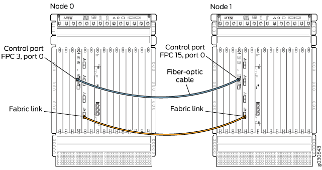
SRX5000シリーズ デバイスにはポートが組み込まれていないため、これらのゲートウェイの制御リンクは、スロット番号オフセットが SRX5400 の場合は 3、SRX5600 デバイスのオフセットが 6、SRX5800 デバイスのスロット番号オフセットが 12 の SPC 上の制御ポートである必要があります。
図 13 は、1 枚の SPC カードを持ち、それぞれに制御リンクが接続された SRX5800 デバイスのペアを示しています。ファブリック リンクは IOC カードを使用して接続されます。デュアル コントロール リンクは、各ノードで 1 枚の SPC カードを使用して設定されます。冗長性を確保するために、各ノード上の 2 つの異なる SPC カードのプライマリおよびセカンダリ制御ポートを分離することを推奨します。
 でのSRX5800 デバイスの接続
図 14 は、2 枚の SPC3 カードを使用して接続されたデュアル コントロール リンクと、IOC カードを使用したデュアル ファブリック リンクを示しています。
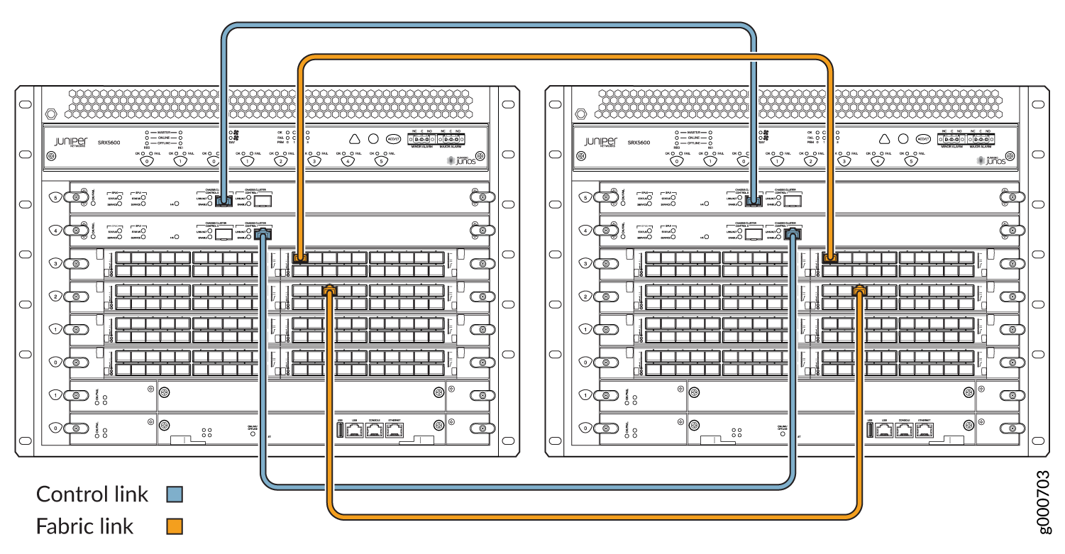 でのSRX5600 デバイスの接続
SRX5000シリーズデバイスで単一のコントロールリンクを接続する場合、コントロールリンクポートはルーティングエンジンスロットと1対1のマッピングになります。ルーティングエンジンがスロット0にある場合、ルーティングエンジンをリンクするには、制御ポート0を使用する必要があります。
SPCが中央点であり、制御ポートをホストしている場合、単一障害点が生じます。プライマリ ノードで SPC がダウンした場合、スプリット ブレインを回避するためにノードが自動的に再起動されます。
 でのSRX5400 デバイスの接続
デュアルコントロールリンクは、スロット数が限られているため、SRX5400デバイスではサポートされていません。