このページの内容
BGPセッションの負荷分散
BGPマルチパスについて
BGPマルチパスでは、複数の内部BGPパスと複数の外部BGPパスを転送テーブルにインストールできます。複数のパスを選択することで、BGPは複数のリンク間でトラフィックを負荷分散できます。
IGPコストをネクストホップと比較した後、BGPパス選択プロセスがタイブレークを行った場合、パスはBGPイコールコストパスとみなされます(そして転送に使用されます)。デフォルトでは、マルチパス対応のBGPネイバーによって学習された、同じネイバー ASを持つすべてのパスが、マルチパス選択プロセスで考慮されます。
通常、BGP は各プレフィックスに対して 1 つの最適なパスのみを選択し、そのルートを転送テーブルにインストールします。BGP マルチパスが有効な場合、デバイスは特定の宛先に到達するように複数のイコールコスト BGP パスを選択し、これらのパスはすべて転送テーブルにインストールされます。BGPは、add-pathが使用されていない限り、ネイバーへのアクティブなパスのみをアドバタイズします。
Junos OS BGPマルチパス機能は、以下のアプリケーションをサポートします。
異なる自律システム(AS)に属している2つのルーティングデバイス間の複数リンクにわたるロードバランシング
同じピアASに属する異なるルーティングデバイスに対する、共通のサブネットまたは複数のサブネット間のロードバランシング
異なる外部コンフェデレーション ピアに属する 2 つのルーティング デバイス間の複数リンクにわたるロード バランシング
外部コンフェデレーション ピアに属するさまざまなルーティング デバイスに対する、共通のサブネットまたは複数のサブネット間のロード バランシング
ロードバランシングの一般的なシナリオでは、顧客はポイントオブプレゼンス(POP)で複数のルーターまたはスイッチにマルチホームされます。デフォルトの動作としては、利用可能なリンクの 1 つのみにすべてのトラフィックを送信します。負荷分散により、トラフィックは 2 つ以上のリンクを使用します。
BGPマルチパスは、MED-plus-IGPコストが同じながら、IGPコストが異なるパスには適用されません。マルチパスのパス選択は、2つのパスが同じIGPプラスIGPコストを持つ場合でも、IGPコスト・メトリックに基づいて行われます。
Junos OSリリース18.1R1以降BGPマルチパス[edit protocols bgp]階層レベルでグローバルにサポートされています。一部の BGP グループとネイバーでマルチパスを選択的に無効にできます。グループまたは特定のBGPネイバーに対してマルチパスオプションを無効にするには[edit protocols bgp group group-name multipath]階層レベルにdisableを含めます。
Junos OSリリース18.1R1以降、すべてのBGPルートが受信されるまでマルチパス計算を遅らせることができます。マルチパスが有効な場合、新しいルートが追加されるたびに、または既存のルートが変更されるたびに、BGPはルートをマルチパスキューに挿入します。BGP add-path 機能によって複数のパスを受信すると、BGP は 1 つのマルチパス ルートを複数回計算する場合があります。マルチパス計算により、RIB(ルーティングテーブルとも呼ばれます)学習速度が遅くなります。RIB 学習を高速化するには、BGP ルートを受信するまで計算マルチパス遅らせるか、BGP ルートが解決されるまで要件に従ってマルチパスビルドジョブの優先度を下げることができます。マルチパス計算を遅らせるには、[edit protocols bgp]階層レベルでdefer-initial-multipath-buildを設定します。または、階層レベルで設定ステートメントを使用してmultipath-build-priorityBGPマルチパスビルドジョブの優先度を下げ[edit protocols bgp]RIB学習を高速化することもできます。
関連項目
例:BGPトラフィックの負荷分散
この例では、複数の等価コスト外部BGP(EBGP)または内部BGP(IBGP)パスをアクティブパスとして選択するようにBGPを設定する方法を示します。
要件
始める前に:
デバイスインターフェイスを設定します。
内部ゲートウェイプロトコル(IGP)を設定します。
BGPを設定します。
ルーティングテーブルからBGPにルート(直接ルートやIGPルートなど)をエクスポートするルーティングポリシーを設定します。
概要
次の手順では、パケット単位のロードバランシングを設定する方法を示します。
[edit policy-options]階層レベルで1つ以上のpolicy-statementステートメントを含め、load-balance per-packetのアクションを定義することで、負荷分散ルーティングポリシーを定義します。policy-statement policy-name { from { match-conditions; route-filter destination-prefix match-type <actions>; prefix-list name; } then { load-balance per-packet; } }ルーティングテーブルから転送テーブルにエクスポートされたルートにポリシーを適用します。これを行うには、
forwarding-tableステートメントとexportステートメントを含めます。forwarding-table { export policy-name; }
VRFルーティングインスタンスにエクスポートポリシーを適用することはできません。
広告中のルートに対応するラベルを割り当てる際に、そのルートのネクストホップが複数存在する場合は、すべてのネクストホップを指定します。
IP ペイロードを含めるように MPLS の転送オプション ハッシュ キーを設定します。
一部のプラットフォームでは、chassis maximum-ecmp ステートメントを使用して、負荷分散されるパスの数を増やすことができます。
このステートメントにより、等価コストの負荷分散パスの最大数を 32、64、128、256、または 512 に変更できます(最大数はプラットフォームごとに異なります。 maximum-ecmpを参照してください)。
マルチパス機能は、BGPをサポートするすべてのプラットフォームでサポートされています。QFXプラットフォームに、いくつかの機能強化が行われました。
-
- Junos OSリリース19.1R1以降、QFX10000スイッチでは、最大128個の等価コストパスを指定することができます。
-
- Junos OSリリース19.2R1以降、QFX10000スイッチでは、最大512個の等価コストパスを指定できます。オプションの コンシステントロードバランシングによる最大512個の等価コストパスの設定についてを参照してください。
この例では、デバイス R1 はAS 64500 にあり、AS 64501 にあるデバイス R2 とデバイス R3 に接続されています。この例では、デバイスR1の設定を示しています。
設定
手順
CLIクイックコンフィグレーション
この例を簡単に設定するには、以下のコマンドをコピーしてテキストファイルに貼り付け、改行を削除して、ネットワーク構成に合わせて必要な詳細を変更し、コマンドを [edit] 階層レベルのCLIにコピー&ペーストしてください。
set protocols bgp group external type external
set protocols bgp group external peer-as 64501
set protocols bgp group external multipath
set protocols bgp group external neighbor 10.0.1.1
set protocols bgp group external neighbor 10.0.0.2
set policy-options policy-statement loadbal from route-filter 10.0.0.0/16 orlonger
set policy-options policy-statement loadbal then load-balance per-packet
set routing-options forwarding-table export loadbal
set routing-options autonomous-system 64500
ステップバイステップの手順
次の例では、設定階層内のさまざまなレベルに移動する必要があります。CLIのナビゲーションについては、『Junos OS CLIユーザーガイド』の「構成モードでのCLIエディターの使用」を参照してください。
BGPピアセッションを設定するには:
BGPグループを設定します。
[edit protocols bgp group external]
user@R1# set type external
user@R1# set peer-as 64501
user@R1# set neighbor 10.0.1.1
user@R1# set neighbor 10.0.0.2
BGPグループが複数のパスを使用できるようにします。
注:BGPマルチパスが受け入れるパスに、同じ隣接自律システム(AS)を要求するデフォルトのチェックを無効にするには、
multiple-asオプションを含めます。[edit protocols bgp group external] user@R1# set multipath
負荷分散ポリシーを設定します。
[edit policy-options policy-statement loadbal]
user@R1# set from route-filter 10.0.0.0/16 orlonger
user@R1# set then load-balance per-packet
負荷分散ポリシーを適用します。
[edit routing-options]
user@R1# set forwarding-table export loadbal
ローカル自律システム(AS)番号を設定します。
[edit routing-options]
user@R1# set autonomous-system 64500
結果
設定モードから、 show protocols、 show policy-options、 show routing-options コマンドを入力して設定を確認します。出力に意図した設定が表示されない場合は、この例の手順を繰り返して設定を修正します。
[edit]
user@R1# show protocols
bgp {
    group external {
        type external;
        peer-as 64501;
        multipath;
        neighbor 10.0.1.1;
        neighbor 10.0.0.2;
    }
}
[edit]
user@R1# show policy-options
policy-statement loadbal {
    from {
        route-filter 10.0.0.0/16 orlonger;
    }
    then {
        load-balance per-packet;
    }
}
[edit]
user@R1# show routing-options
autonomous-system 64500;
forwarding-table {
    export loadbal;
}
デバイスの設定が完了したら、設定モードから commit を入力します。
検証
設定が正常に機能していることを確認します。
ルートの検証
目的
隣接する AS の両方のルーターからルートが学習されていることを確認します。
アクション
動作モードから、 show route コマンドを実行します。
user@R1> show route 10.0.2.0
inet.0: 12 destinations, 15 routes (12 active, 0 holddown, 0 hidden)
+ = Active Route, - = Last Active, * = Both

10.0.2.0/30        *[BGP/170] 03:12:32, localpref 100
                      AS path: 64501 I
                      to 10.0.1.1 via ge-1/2/0.0
                    > to 10.0.0.2 via ge-1/2/1.0
                    [BGP/170] 03:12:32, localpref 100
                      AS path: 64501 I
                    > to 10.0.1.1 via ge-1/2/0.0
user@R1> show route 10.0.2.0 detail
inet.0: 12 destinations, 15 routes (12 active, 0 holddown, 0 hidden)
10.0.2.0/30 (2 entries, 1 announced)
        *BGP    Preference: 170/-101
                Next hop type: Router, Next hop index: 262142
                Next-hop reference count: 3
                Source: 10.0.0.2
                Next hop: 10.0.1.1 via ge-1/2/0.0
                Next hop: 10.0.0.2 via ge-1/2/1.0, selected
                State: <Active Ext>
                Local AS: 64500 Peer AS: 64501
                Age: 3:18:30
                Task: BGP_64501.10.0.0.2+55402
                Announcement bits (1): 2-KRT
                AS path: 64501 I
                Accepted Multipath
                Localpref: 100
                Router ID: 192.168.2.1
         BGP    Preference: 170/-101
                Next hop type: Router, Next hop index: 602
                Next-hop reference count: 5
                Source: 10.0.1.1
                Next hop: 10.0.1.1 via ge-1/2/0.0, selected
                State: <NotBest Ext>
                Inactive reason: Not Best in its group - Active preferred
                Local AS: 64500 Peer AS: 64501
                Age: 3:18:30
                Task: BGP_64501.10.0.1.1+53135
                AS path: 64501 I
                Accepted
                Localpref: 100
                Router ID: 192.168.3.1
意味
アスタリスク(*)で示されるアクティブパスには、10.0.1.1と10.0.0.2の2つのネクストホップがあり、宛先は10.0.2.0です。10.0.1.1 ネクストホップは、非アクティブなパスからアクティブなパスにコピーされます。
show route detailコマンドの出力は、1 つのゲートウェイをselectedとして指定します。この出力は、ロードバランシングのコンテキストでは混乱する可能性があります。選択したゲートウェイは、Junos OS がパケット単位の負荷分散を実行していない場合に、どのゲートウェイをカーネルにインストールするかを決定する以外にも、多くの目的で使用されます。例えば、ping mplsコマンドは、パケットを送信するときに選択したゲートウェイを使用します。マルチキャストプロトコルでは、アップストリームのインターフェイスを決定するために、選択したゲートウェイを使用する場合があります。そのため、Junos OSが転送テーブルのポリシーによってパケット単位の負荷分散を実行している場合でも、選択したゲートウェイ情報は他の目的で必要となります。トラブルシューティングのために、選択したゲートウェイを表示すると便利です。さらに、転送テーブルポリシーを使用して、カーネルにインストールされているものを上書きすることができます(たとえば、install-nexthopアクションを使用することで)。この場合、転送テーブルにインストールされているネクストホップゲートウェイは、show routeコマンドで表示される全ゲートウェイのサブセットである可能性があります。
転送の検証
目的
両方のネクストホップが転送テーブルにインストールされていることを確認します。
アクション
動作モードから、 show route forwarding-table コマンドを実行します。
user@R1> show route forwarding-table destination 10.0.2.0
Routing table: default.inet
Internet:
Destination        Type RtRef Next hop           Type Index NhRef Netif
10.0.2.0/30        user     0                    ulst 262142     2
                              10.0.1.1           ucst   602     5 ge-1/2/0.0
                              10.0.0.2           ucst   522     6 ge-1/2/1.0
オプションのコンシステントロードバランシングによる最大512本のイコールコストパスの設定の理解
ECMP(イコールコスト マルチパス)機能は、外部 BGP ピアに対して最大 512 本のパスを設定することができます。ECMP ネクスト ホップを最大 512 個まで設定できるため、指定したルーティング デバイスとの直接 BGPピア接続の数を増やすことができ、遅延を改善し、データ フローを最適化できます。その ECMP 設定に、オプションで一貫したロードバランシングを含めることができます。一貫したロードバランシングにより、ECMP メンバー(つまりパス)に障害が発生した場合、障害が発生したメンバーを流れるフローのみが他のアクティブな ECMP メンバーに再分配されます。また、ECMP メンバーが追加された場合、既存の EMCP メンバーから新しい ECMP メンバーへのフローの再分配が最小限に抑えられるように、一貫したロードバランシングが行われます。
- 256 から 512 の等コスト パスを設定する際のガイドラインと制限事項(オプションで一貫したロード バランシングを設定可能)
- 最大 512 の ECMP ネクスト ホップを設定し、オプションで一貫したロード バランシングを設定する手順を説明します。
256 から 512 の等コスト パスを設定する際のガイドラインと制限事項(オプションで一貫したロード バランシングを設定可能)
この機能は、シングルホップの外部 BGP ピアにのみ適用されます。(この機能は MPLS ルートには適用されません。
デバイスのルーティング プロセス(RPD)は 64 ビット モードをサポートしている必要があります。32ビットRPDはサポートされていません。
この機能は、ユニキャストトラフィックにのみ適用されます。
トラフィック パターンとハードウェアのハッシュ フロー セット テーブルの構成に依存します。一貫したハッシュにより、グループへのメンバーの追加や削除があった場合に、フローからデスティネーション リンクへの再マッピングを 最小限に抑えることができます 。
hash-mode、inet、inet6、またはlayer2のいずれかのオプションでset forwarding-options enhanced-hash-keyを設定すると、新しいハッシュ パラメータがフローの新しいハッシュ インデックスを生成し、新しい宛先リンクになる可能性があるため、一部のフローで宛先リンクが変更される場合があります。この機能は、可能な限り最高のハッシュ精度を達成するために、128 以上のネクストホップ構成に対して、 カスケードト ポロジーを使用してネクストホップ構造を実装します。そのため、ハッシュ化の精度は、カスケード トポロジーを必要としない 128 未満の ECMP ネクスト ホップ構成の場合よりもやや劣ります。
ローカル ルート修復中に、影響を受けた ECMP パス上の既存のフローと、影響を受けた ECMP パス上を流れる新しいフローがパスを切り替える可能性があり、トラフィックの偏りが顕著になる可能性があります。しかし、そのような歪みは、その後のグローバル ルート修復の際に修正されます。
maximum-ecmp値を増やすと、ルートプレフィックスに対する次のネクストホップ変更イベントで一貫性ハッシュが失われます。既存の ECMP グループに新しいパスを追加すると、影響を受けていないパス上の一部のフローが新しく追加されたパスに移動することがあります。
高速リルート(FRR)は、一貫性のあるハッシュでは機能しない場合があります。
ECMP のような完全なトラフィック分散を実現することはできません。他のパスよりも多くの「バケット」を持つパスは、バケットの数が少ないパスよりも多くのトラフィック フローを持ちます( バケット とは、ECMP メンバーインデックスにマッピングされた負荷分散テーブルの分配リストのエントリーのことです)。
ネットワーク トポロジー変更時に、ネットワーク プレフィックスが以前の ECMP ネクスト ホップのすべてのプロパティを持たない新しい ECMP ネクストホップを指すため、場合によってはネットワーク プレフィックスに対する一貫したハッシュが失われます。
複数のネットワーク プレフィックスが同じ ECMP ネクストホップを指し、そのうちの 1 つ以上のプレフィックスが
consistent-hashステートメントで有効になっている場合、その同じ ECMP ネクスト ホップを指す すべての ネットワーク プレフィックスが一貫したハッシング動作を示します。コンシステント ハッシュは、イコール コスト BGP ルートベースの ECMP グループでのみサポートされます。BGPルートより優先される他のプロトコルやスタティックルートが設定されている場合、コンシステントハッシュはサポートされません。
コンシステント ハッシュは、次の機能の設定と組み合わせた場合に制限が発生する場合があります。これらの機能には、トンネルの終端があるか、パスの選択にハッシュを使用しないトラフィック エンジニアリングがあるためです。BUM トラフィック;EVPN-VXLAN;および MPLS TE、自動帯域幅。
最大 512 の ECMP ネクスト ホップを設定し、オプションで一貫したロード バランシングを設定する手順を説明します。
最大 512 個のネクスト ホップを設定できるようになったら、以下の設定方法を使用してください。
ECMP ネクスト ホップの最大数を設定します(例:512 ECMP ネクストホップを設定する)。
[edit]
user@host# set chassis maximum-ecmp 512
ルーティングポリシーを作成し、パケット単位のロードバランシングを有効にすることで、システム上でグローバルにECMPを有効にする。
[edit]
user@host# set routing-options forwarding-table export load-balancing-policy
user@host# set policy-options policy-statement load-balancing-policy then load-balance per-packet
1つまたは複数の宛先プレフィックスへの着信ルートをマッチングする別のルーティングポリシーを作成し、選択したプレフィックスで耐障害性を有効にします(例)。
[edit]
user@host# set policy-options policy-statement c-hash from route-filter 20.0.0.0/24 orlonger
 user@host# set policy-options policy-statement c-hash then load-balance consistent-hash
外部ピアの BGP グループに eBGP インポートポリシー(例:「c-hash」)をBGPに適用します。
[edit]
user@host# set protocols bgp import c-hash
イコール コスト パスの設定の詳細については、このドキュメントの前半で紹介した 例:BGPトラフィックの負荷分散を参照してください。
(オプション)一貫性のあるロードバランシング(一貫性のあるハッシュとも呼ばれる)の設定の詳細については、ECMP グループの一貫性のあるロード バランシングの設定を参照してください
関連項目
例:リモートネクストホップを受け入れるためのシングルホップEBGPピアの設定
この例では、シングルホップ外部BGP(EBGP)ピアが、共通のサブネットを共有していないリモートネクストホップを受け入れるように設定する方法を示します。
要件
この例を設定する前に、デバイスの初期化以外の特別な設定は必要ありません。
概要
状況によっては、共通のサブネットを共有していないリモートネクストホップを受け入れるようにシングルホップEBGPピアを設定する必要があります。デフォルトの動作は、破棄する共通のサブネットの共有と見なされないシングルホップEBGPピアから受信したネクストホップアドレスの動作です。また、シングルホップEBGPピアが、直接接続されていないリモートネクストホップを受け取ることができるため、シングルホップEBGPネイバーをマルチホップセッションとして設定する必要がなくなります。このような状況でマルチホップセッションを設定すると、このEBGPピアを介して学習したすべてのネクストホップルートには、共通のサブネットを共有していても間接的なラベルが付けられます。この状況は、これらのネクストホップアドレスを含むルート上で再帰的に解決されたルートのマルチパス機能を破壊します。 accept-remote-nexthop ステートメントを設定することで、シングルホップEBGPピアはリモートネクストホップを受け取ることができます。これにより、これらのネクストホップアドレス上で解決されたルートのマルチパス機能が復元されます。このステートメントは、BGPのグローバル、グループ、およびネイバー階層レベルで設定できます。また、このステートメントは、論理システムとVPNルーティングおよび転送(VRF)ルーティングインスタンスタイプでもサポートされています。リモートネクストホップとEBGPピアの両方BGP、RFC 2918( BGP-4のルート更新機能)で定義されているルート更新をサポートする必要があります。リモートピアがBGPルートリフレッシュをサポートしていない場合、セッションはリセットされます。
シングルホップEBGPピアは、デフォルトで、自身のアドレスをネクストホップとしてアドバタイズします。別のネクストホップをアドバタイズする場合は、EBGPピアでインポートルーティングポリシーを定義する必要があります。シングルホップEBGPピアがリモートネクストホップを受け取れるようにすると、EBGPピアでインポートルーティングポリシーを設定することもできます。ただし、リモートネクストホップを設定している場合は、ルーティングポリシーは必要ありません。
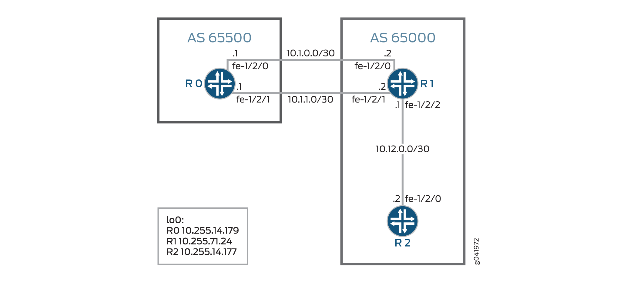
この例では、シングルホップ外部BGPピア(デバイス R1)が 10.1.230.0/23 ネットワークへのルートに対してリモート ネクストホップ 10.1.10.10 を受け取れるようにするインポート ルーティングポリシー agg_route が含まれています。 [edit protocols bgp] 階層レベルでは、この例は、ポリシーを外部BGPピアに適用する import agg_route ステートメントと、シングルホップEBGPピアがリモートネクストホップを受け取れるようにする accept-remote-nexthop ステートメントを含みます。
図2は、サンプルトポロジーを示しています。
 を受け取るためのトポロジー
設定
CLIクイックコンフィグレーション
この例をすばやく設定するには、以下のコマンドをコピーしてテキストファイルに貼り付け、改行を削除して、ネットワーク構成に合わせて必要な詳細を変更してから、コマンドを [edit] 階層レベルのCLIにコピー&ペーストします。
デバイスR0
set interfaces fe-1/2/0 unit 0 family inet address 10.1.0.1/30
set interfaces fe-1/2/1 unit 0 family inet address 10.1.1.1/30
set interfaces lo0 unit 0 family inet address 10.255.14.179/32
set protocols bgp group ext type external
set protocols bgp group ext export test_route
set protocols bgp group ext export agg_route
set protocols bgp group ext peer-as 65000
set protocols bgp group ext multipath
set protocols bgp group ext neighbor 10.1.0.2
set protocols bgp group ext neighbor 10.1.1.2
set policy-options policy-statement agg_route term 1 from protocol static
set policy-options policy-statement agg_route term 1 from route-filter 10.1.230.0/23 exact
set policy-options policy-statement agg_route term 1 then accept
set policy-options policy-statement test_route term 1 from protocol static
set policy-options policy-statement test_route term 1 from route-filter 10.1.10.10/32 exact
set policy-options policy-statement test_route term 1 then accept
set routing-options static route 10.1.10.10/32 reject
set routing-options static route 10.1.230.0/23 reject
set routing-options autonomous-system 65500
デバイスR1
set interfaces fe-1/2/0 unit 0 family inet address 10.1.0.2/30
set interfaces fe-1/2/1 unit 0 family inet address 10.1.1.2/30
set interfaces fe-1/2/2 unit 0 family inet address 10.12.0.1/30
set interfaces lo0 unit 2 family inet address 10.255.71.24/32
set protocols bgp accept-remote-nexthop
set protocols bgp group ext type external
set protocols bgp group ext import agg_route
set protocols bgp group ext peer-as 65500
set protocols bgp group ext multipath
set protocols bgp group ext neighbor 10.1.0.1
set protocols bgp group ext neighbor 10.1.1.1
set protocols bgp group int type internal
set protocols bgp group int local-address 10.255.71.24
set protocols bgp group int neighbor 10.255.14.177
set protocols ospf area 0.0.0.0 interface fe-1/2/1.4
set protocols ospf area 0.0.0.0 interface 10.255.71.24
set policy-options policy-statement agg_route term 1 from protocol bgp
set policy-options policy-statement agg_route term 1 from route-filter 10.1.230.0/23 exact
set policy-options policy-statement agg_route term 1 then next-hop 10.1.10.10
set policy-options policy-statement agg_route term 1 then accept
set routing-options autonomous-system 65000
デバイスR2
set interfaces fe-1/2/0 unit 0 family inet address 10.12.0.2/30
set interfaces lo0 unit 0 family inet address 10.255.14.177/32
set protocols bgp group int type internal
set protocols bgp group int local-address 10.255.14.177
set protocols bgp group int neighbor 10.255.71.24
set protocols ospf area 0.0.0.0 interface fe-1/2/0.6
set protocols ospf area 0.0.0.0 interface 10.255.14.177
set routing-options autonomous-system 65000
デバイスR0
ステップバイステップの手順
次の例では、設定階層のさまざまなレベルに移動する必要があります。CLIのナビゲーションについては、『Junos OS CLIユーザーガイド』の「設定モードでのCLIエディタの使用」を参照してください。
デバイスR0を設定するには:
-
インターフェイスを設定します。
[edit interfaces fe-1/2/0 unit 0]
user@R0# set family inet address 10.1.0.1/30
[edit interfaces fe-1/2/1 unit 0]
user@R0# set family inet address 10.1.1.1/30
[edit interfaces lo0 unit 0]
user@R0# set family inet address 10.255.14.179/32
-
EBGPを設定します。
[edit protocols bgp group ext]
user@R0# set type external
user@R0# set peer-as 65000
user@R0# set neighbor 10.1.0.2
user@R0# set neighbor 10.1.1.2
-
デバイスR0とデバイスR1の間のマルチパスBGPを有効にします。
[edit protocols bgp group ext]
user@R0# set multipath
-
リモートネットワークへのスタティックルートを設定します。 これらのルートはトポロジーの一部ではありません。これらのルートの目的は、この例で機能を示すことです。
[edit routing-options]
user@R0# set static route 10.1.10.10/32 reject
user@R0# set static route 10.1.230.0/23 reject
-
スタティックルートを受け取るルーティングポリシーを設定します。
[edit policy-options policy-statement agg_route term 1]
user@R0# set from protocol static
user@R0# set from route-filter 10.1.230.0/23 exact
user@R0# set then accept
[edit policy-options policy-statement test_route term 1]
user@R0# set from protocol static
user@R0# set from route-filter 10.1.10.10/32 exact
user@R0# set then accept
-
agg_routeポリシーとtest_routeポリシーをルーティングテーブルからBGPにエクスポートします。[edit protocols bgp group ext] user@R0# set export test_route user@R0# set export agg_route
-
自律システム(AS)番号を設定します。
[edit routing-options]
user@R0# set autonomous-system 65500
結果
設定モードから、 show interfaces、 show policy-options、 show protocols、 show routing-options コマンドを入力して設定を確認します。出力に意図した設定が表示されない場合は、この例の手順を繰り返して設定を修正します。
user@R0# show interfaces
fe-1/2/0 {
    unit 0 {
        family inet {
            address 10.1.0.1/30;
        }
    }
}
fe-1/2/1 {
    unit 0 {
        family inet {
            address 10.1.1.1/30;
        }
    }
}
lo0 {
    unit 0 {
        family inet {
            address 10.255.14.179/32;
        }
    }
}
user@R0# show policy-options
policy-statement agg_route {
    term 0 {
        from {
            protocol static;
            route-filter 10.1.230.0/23 exact;
        }
        then accept;
    }
}
policy-statement test_route {
    term 1 {
        from {
            protocol static;
            route-filter 10.1.10.10/32 exact;
        }
        then accept;
    }
}
user@R0# show protocols
bgp {
    group ext {
        type external;
        export [ test_route agg_route ];
        peer-as 65000;
        multipath;
        neighbor 10.1.0.2;
        neighbor 10.1.1.2;
    }
}
user@R0# show routing-options
static {
    route 10.1.10.10/32 reject;
    route 10.1.230.0/23 reject;
}
autonomous-system 65500;
デバイスの設定が完了したら、設定モードから commit を入力します。
デバイスR1の設定
ステップバイステップの手順
次の例では、設定階層のさまざまなレベルに移動する必要があります。CLIのナビゲーションについては、『Junos OS CLIユーザーガイド』の「設定モードでのCLIエディタの使用」を参照してください。
デバイスR1を設定するには:
-
インターフェイスを設定します。
[edit interfaces fe-1/2/0 unit 0]
user@R1# set family inet address 10.1.0.2/30
[edit interfaces fe-1/2/1 unit 0]
user@R1# set family inet address 10.1.1.2/30
[edit interfaces fe-1/2/2 unit 0]
user@R1# set family inet address 10.12.0.1/30
[edit interfaces lo0 unit 0]
user@R1# set family inet address 10.255.71.24/32
-
OSPFを設定します。
[edit protocols ospf area 0.0.0.0]
user@R1# set interface fe-1/2/1.0
user@R1# set interface 10.255.71.24
-
デバイスR1がリモートネクストホップを受け取れるようにします。
[edit protocols bgp]
user@R1# set accept-remote-nexthop
-
IBGPを設定します。
[edit protocols bgp group int]
user@R1# set type internal
user@R1# set local-address 10.255.71.24
user@R1# set neighbor 10.255.14.177
-
EBGPを設定します。
[edit protocols bgp group ext]
user@R1# set type external
user@R1# set peer-as 65500
user@R1# set neighbor 10.1.0.1
user@R1# set neighbor 10.1.1.1
-
デバイスR0とデバイスR1の間のマルチパスBGPを有効にします。
[edit protocols bgp group ext]
user@R1# set multipath
-
シングルホップ外部BGPピア(デバイスR1)が、10.1.230.0/23ネットワークへのルートに対してリモートネクストホップ10.1.10.10を受け取れるようにするルーティングポリシーを設定します。
[edit policy-options policy-statement agg_route term 1]
user@R1# set from protocol bgp
user@R1# set from route-filter 10.1.230.0/23 exact
user@R1# set then next-hop 10.1.10.10
user@R1# set then accept
-
デバイスR1のルーティングテーブルに
agg_routeポリシーをインポートします。[edit protocols bgp group ext] user@R1# set import agg_route
-
自律システム(AS)番号を設定します。
[edit routing-options]
user@R1# set autonomous-system 65000
結果
設定モードから、 show interfaces、 show policy-options、 show protocols、 show routing-options コマンドを入力して設定を確認します。出力に意図した設定が表示されない場合は、この例の手順を繰り返して設定を修正します。
user@R1# show interfaces
fe-1/2/0 {
    unit 0 {
        family inet {
            address 10.1.0.2/30;
        }
    }
}
fe-1/2/1 {
    unit 0 {
        family inet {
            address 10.1.1.2/30;
        }
    }
}
fe-1/2/2 {
    unit 0 {
        family inet {
            address 10.12.0.1/30;
        }
    }
}
lo0 {
    unit 0 {
        family inet {
            address 10.255.71.24/32;
        }
    }
}
user@R1# show policy-options
policy-statement agg_route {
    term 1 {
        from {
            protocol bgp;
            route-filter 10.1.230.0/23 exact;
        }
        then {
            next-hop 10.1.10.10;
            accept;
        }
    }
}
user@R1# show protocols
bgp {
    accept-remote-nexthop;
    group ext {
        type external;
        import agg_route;
        peer-as 65500;
        multipath;
        neighbor 10.1.0.1;
        neighbor 10.1.1.1;
    }
    group int {
        type internal;
        local-address 10.255.71.24;
        neighbor 10.255.14.177;
    }
}
ospf {
    area 0.0.0.0 {
        interface fe-1/2/1.0;
        interface 10.255.71.24;
    }
}
user@R1# show routing-options
autonomous-system 65000;
デバイスの設定が完了したら、設定モードから commit を入力します。
デバイスR2の設定
ステップバイステップの手順
次の例では、設定階層のさまざまなレベルに移動する必要があります。CLIのナビゲーションについては、『Junos OS CLIユーザーガイド』の「設定モードでのCLIエディタの使用」を参照してください。
デバイスR2を設定するには:
-
インターフェイスを設定します。
[edit interfaces fe-1/2/0 unit 0]
user@R2# set family inet address 10.12.0.2/30
[edit  interfaces lo0 unit 0]
user@R2# set family inet address 10.255.14.177/32
-
OSPFを設定します。
[edit protocols ospf area 0.0.0.0]
user@R2# set interface fe-1/2/0.0
user@R2# set interface 10.255.14.177
-
IBGPを設定します。
[edit protocols bgp group int]
user@R2# set type internal
user@R2# set local-address 10.255.14.177
user@R2# set neighbor 10.255.71.24
-
自律システム(AS)番号を設定します。
[edit routing-options]
user@R1# set autonomous-system 65000
結果
設定モードから、 show interfaces、 show protocols、 show routing-options コマンドを入力して設定を確認します。出力に意図した設定が表示されない場合は、この例の手順を繰り返して設定を修正します。
user@R2# show interfaces
fe-1/2/0 {
    unit 0 {
        family inet {
            address 10.12.0.2/30;
        }
    }
}
lo0 {
    unit 0 {
        family inet {
            address 10.255.14.177/32;
        }
    }
}
user@R2# show protocols
bgp {
    group int {
        type internal;
        local-address 10.255.14.177;
        neighbor 10.255.71.24;
    }
}
ospf {
    area 0.0.0.0 {
        interface fe-1/2/0.0;
        interface 10.255.14.177;
    }
}
user@R2# show routing-options
autonomous-system 65000;
デバイスの設定が完了したら、設定モードから commit を入力します。
検証
設定が正常に機能していることを確認します。
間接ネクストホップによるマルチパスルートがルーティングテーブルに存在することの確認
目的
デバイスR1に10.1.230.0/23ネットワークへのルートがあることを確認します。
アクション
動作モードから、 show route 10.1.230.0 extensive コマンドを入力します。
user@R1> show route 10.1.230.0 extensive
inet.0: 11 destinations, 13 routes (11 active, 0 holddown, 0 hidden)
Restart Complete
10.1.230.0/23 (2 entries, 1 announced)
TSI:
KRT in-kernel 10.1.230.0/23 -> {indirect(262142)}
Page 0 idx 1 Type 1 val 9168f6c
    Nexthop: 10.1.10.10
    Localpref: 100
    AS path: [65000] 65500 I
    Communities:
Path 10.1.230.0 from 10.1.0.1 Vector len 4.  Val: 1
        *BGP    Preference: 170/-101
                Next hop type: Indirect
                Address: 0x90c44d8
                Next-hop reference count: 4
                Source: 10.1.0.1
                Next hop type: Router, Next hop index: 262143
                Next hop: 10.1.0.1 via fe-1/2/0.0, selected
                Next hop: 10.1.1.1 via fe-1/2/2.0
                Protocol next hop: 10.1.10.10
                Indirect next hop: 91c0000 262142
                State: <Active Ext>
                Local AS: 65000 Peer AS: 65500
                Age: 2:55:31    Metric2: 0
                Task: BGP_65500.10.1.0.1+64631
                Announcement bits (3): 2-KRT 3-BGP_RT_Background 4-Resolve tree 1
                AS path: 65500 I
                Accepted Multipath
                Localpref: 100
                Router ID: 10.255.14.179
                Indirect next hops: 1
                        Protocol next hop: 10.1.10.10
                        Indirect next hop: 91c0000 262142
                        Indirect path forwarding next hops: 2
                                Next hop type: Router
                                Next hop: 10.1.0.1 via fe-1/2/0.0
                                Next hop: 10.1.1.1 via fe-1/2/2.0
                        10.1.10.10/32 Originating RIB: inet.0
                          Node path count: 1
                          Forwarding nexthops: 2
                                Nexthop: 10.1.0.1 via fe-1/2/0.0
                                Nexthop: 10.1.1.1 via fe-1/2/2.0
         BGP    Preference: 170/-101
                Next hop type: Indirect
                Address: 0x90c44d8
                Next-hop reference count: 4
                Source: 10.1.1.1
                Next hop type: Router, Next hop index: 262143
                Next hop: 10.1.0.1 via fe-1/2/0.0, selected
                Next hop: 10.1.1.1 via fe-1/2/2.0
                Protocol next hop: 10.1.10.10
                Indirect next hop: 91c0000 262142
                State: <NotBest Ext>
                Inactive reason: Not Best in its group - Update source
                Local AS: 65000 Peer AS: 65500
                Age: 2:55:27    Metric2: 0
                Task: BGP_65500.10.1.1.1+53260
                AS path: 65500 I
                Accepted
                Localpref: 100
                Router ID: 10.255.14.179
                Indirect next hops: 1
                        Protocol next hop: 10.1.10.10
                        Indirect next hop: 91c0000 262142
                        Indirect path forwarding next hops: 2
                                Next hop type: Router
                                Next hop: 10.1.0.1 via fe-1/2/0.0
                                Next hop: 10.1.1.1 via fe-1/2/2.0
                        10.1.10.10/32 Originating RIB: inet.0
                          Node path count: 1
                          Forwarding nexthops: 2
                                Nexthop: 10.1.0.1 via fe-1/2/0.0
                                Nexthop: 10.1.1.1 via fe-1/2/2.0
意味
出力は、デバイスR1にマルチパス機能が有効になっている10.1.230.0ネットワークへのルートがあることを示しています(Accepted Multipath)。また、出力は、ルートに 10.1.10.10 の間接ネクストホップがあることを示しています。
accept-remote-nexthopステートメントの無効化と再活性化
目的
accept-remote-nexthopステートメントを無効にする場合は、間接ネクストホップを持つマルチパスルートがルーティングテーブルから削除されていることを確認してください。
アクション
-
設定モードから、
deactivate protocols bgp accept-remote-nexthopコマンドを入力します。user@R1# deactivate protocols bgp accept-remote-nexthop user@R1# commit
-
動作モードから、
show route 10.1.230.0コマンドを入力します。user@R1> show route 10.1.230.0
-
設定モードから、
activate protocols bgp accept-remote-nexthopコマンドを入力してステートメントを再活性化します。user@R1# activate protocols bgp accept-remote-nexthop user@R1# commit
-
動作モードから、
show route 10.1.230.0コマンドを再入力します。user@R1> show route 10.1.230.0 inet.0: 11 destinations, 13 routes (11 active, 0 holddown, 0 hidden) Restart Complete + = Active Route, - = Last Active, * = Both 10.1.230.0/23 *[BGP/170] 03:13:19, localpref 100 AS path: 65500 I > to 10.1.0.1 via fe-1/2/0.0 to 10.1.1.1 via fe-1/2/2.0 [BGP/170] 03:13:15, localpref 100, from 10.1.1.1 AS path: 65500 I > to 10.1.0.1 via fe-1/2/0.0 to 10.1.1.1 via fe-1/2/2.0
意味
accept-remote-nexthop ステートメントが無効化されると、10.1.230.0 ネットワークへのマルチパスルートがルーティングテーブルから削除されます。
パスに割り当てられた帯域幅が不均等なBGPトラフィックのロードバランシングの理解
マルチパスオプションは、アクティブなルート決定プロセスからタイブレイカーを削除します。従って、複数ソースから学習した等コストのBGPルートを転送テーブルにインストールすることができます。ただし、利用可能なパスが等コストでない場合は、トラフィックを非対称にロードバランンシングすることをお勧めします。
複数のネクストホップを転送テーブルにインストールすると、特定の転送ネクストホップが、Junos OSのプレフィックス単位のロードバランシングアルゴリズムによって選択されます。このプロセスは、パケットの送信元アドレスと宛先アドレスに対してハッシュを行い、利用可能なネクストホップの1つにプレフィックスペアを決定的にマップします。プレフィックス単位マッピングは、インターネットピアリング交換で起こり得るハッシュ機能が多数のプレフィックスとともに提示されている場合に最も効果的に機能し、通信ノードのペア間のパケットの並べ替えを防止する役割を果たします。
エンタープライズネットワークは、通常、デフォルト動作を変更して、 パケット単位 のロードバランシングアルゴリズムを起動します。ここでパケット単位ということを強調しているのは、その用途が、元のインターネットプロセッサASICの動作履歴に由来する誤った名称だからです。実際には、現在のジュニパーネットワークスルーターは、プレフィックス単位(デフォルト)とフロー単位のロードバランシングをサポートしています。後者では、送信元アドレス、宛先アドレス、トランスポートプロトコル、着信インターフェイス、アプリケーションポートの一部を含む、さまざまなレイヤー3およびレイヤー4ヘッダーに対するハッシュを要します。その効果は、個々のフローが特定のネクストホップにハッシュされるようになったため、特に少数の発信元と宛先のペア間のルーティングの場合、利用可能なネクストホップ間でより均等な分散が行われるようになります。
パケット単位のロードバランシングでは、2つのエンドポイント間の通信ストリームを構成するパケットの並べ替えが行われる可能性がありますが、個々のフロー内のパケットは正しいシーケンスを維持します。プレフィックス単位とパケット単位のどちらのロードバランシングを選択する場合でも、アクセスリンクの非対称性には技術的な課題が発生する可能性があります。どちらの場合も、例えば、T1リンクにマッピングされたプレフィックスまたはフローは、例えばファストイーサネットアクセスリンクにマッピングされたフローと比較すると、パフォーマンスの低下を示します。さらに悪いことに、トラフィック負荷が多い場合、等しいロードバランシングを試みても、T1リンクが完全に飽和状態になり、パケット損失から生じるセッション中断が生じる可能性があります。
幸いなことに、ジュニパーネットワークスのBGP実装は、帯域幅コミュニティーの概念をサポートしています。この拡張コミュニティーは特定のネクストホップの帯域幅を符号化し、マルチパスと組み合わされた場合、ロードバランシングアルゴリズムは、相対帯域幅に比例する一連のネクストホップにフローを分散します。つまり、10Mbpsと1Mbpsのネクストホップがある場合、平均9フローが、低速のものすべてを高速ネクストホップにマップします。
BGP帯域幅コミュニティーの使用は、パケット単位のロードバランシングでのみサポートされています。
設定タスクは、次の 2 つの部分で構成されています。
外部BGP(EBGP)ピアリングセッションを設定し、マルチパスを有効にし、リンク速度を反映する帯域幅コミュニティーでルートをタグ付けするインポートポリシーを定義します。
トラフィックの最適な分散のために、パケット単位(実際にはフロー単位)のロードバランシングを有効にします。
関連項目
BGPリンク帯域幅コミュニティ
概要
BGP実装内では、リンク帯域幅拡張コミュニティが特定のネクストホップの帯域幅をエンコードします。BGPは、BGPリンクの速度をリモートピアに通信することで、BGPトラフィックの負荷分散を支援します。ネットワーク管理者がリンク帯域幅コミュニティとマルチパスを組み合わせると、選択したロードバランシングアルゴリズムが、相対帯域幅に比例する一連のネクストホップにトラフィックフローを分散します。
BGPリンク帯域幅拡張コミュニティが自律システム(AS)全体の推移的な属性である場合、BGPグループはリンク帯域幅拡張コミュニティを隣接するASにアドバタイズします。BGPリンク帯域幅コミュニティを非推移的属性として使用することを選択することで、ルーターはAS境界でリンク帯域幅コミュニティをドロップします。BGPグループは、外部BGP(EBGP)ネイバーに非推移的リンク帯域幅コミュニティをアドバタイズしません。
また、帯域幅を自動的に検知し、グループまたはネイバーレベルでコミュニティをインポートするようにBGPを設定することもできます。このリンク帯域幅オートセンス機能を使用すると、ネットワークは、デバイスが BGP ルートを受信したインターフェイスの速度にリンク帯域幅値を自動的に設定できます。
パケット単位のロードバランシングのみが、BGPリンク帯域幅コミュニティをサポートします。
利点
-
マルチパスを有効にすると、リンク帯域幅は不等ロードバランシングに対して重み付けされた等価コストマルチパス(WECMP)を提供します。
-
高帯域幅のリンクが、低帯域幅のリンクよりも多くのフローを伝送することを保証します。
-
交通渋滞の可能性を軽減します。
設定
帯域幅
デフォルトでは、リンク帯域幅コミュニティは推移的です。これらのステートメントのいずれかを使用して、リンク帯域幅コミュニティを推移的として設定できます。
set policy-options community name members bandwidth:value
set policy-options community name members bandwidth-transitive:value
非推移的にするには、以下の設定を使用します。
set policy-options community policy-name members bandwidth-non-transitive:value
非推移的上書き
非推移的設定をオーバーライドすることで、リンク帯域幅が非推移的であっても、BGPグループがEBGPセッションを介してリンク帯域幅拡張コミュニティを送信するようにすることができます。EBGPネイバーを介して非推移的リンク帯域幅コミュニティを送信するには、以下の設定を含めます。
set protocols bgp group group-name send-non-transitive-link-bandwidth
send-non-transitive-link-bandwidthステートメントは、発信されたリンク帯域幅コミュニティと、受信して再アドバタイズされたコミュニティを区別するものではありません。このオプションを有効にすると、BGPはすべての非推移的リンク帯域幅コミュニティをEBGPネイバーにアドバタイズします。
集合帯域幅
デフォルトでは、集約リンク帯域幅コミュニティは推移的です。これらのステートメントのいずれかを使用して、リンク帯域幅コミュニティを推移的として設定できます。
set policy-options policy-statement name then aggregate-bandwidth
set policy-options policy-statement name then aggregate-bandwidth transitive
非推移的にするには、以下の設定を使用します。
set policy-options policy-statement policy-name then aggregate-bandwidth non-transitive
総リンク帯域幅をアドバタイズグループ内のピアの数で割るには、 divide-equal ステートメントを有効にします。
set policy-options policy-statement policy-name then aggregate-bandwidth divide-equal
オートセンス
オートセンスは、シングルホップEBGPセッションに対してのみ有効にできます。
BGPグループのオートセンスを設定します。
neighbor階層でauto-senseステートメントを設定して、そのBGPネイバーへの帯域幅を検出して保存します。group階層で設定して、そのBGPグループの下のすべてのネイバーの帯域幅を検出して保存します。set protocols bgp group group-name link-bandwith auto-sense set protocols bgp group group-name neighbor link-bandwith auto-sense
auto-link-bandwidthをtransitiveまたはnon-transitiveに設定してインポートポリシーを設定します。指定しない場合、デフォルトではauto-link-bandwidthは推移的です。set protocols bgp group group-name import policy-name set policy-options policy-statement policy-name then auto-link-bandwidth non-transitive
(オプション)帯域幅が増加したときにリンク帯域幅値が頻繁に変化するのを防ぐために、オートセンスホールドダウンタイマーを設定することができます。ホールドダウンタイマーは、帯域幅が増加した場合にのみ作動します。デフォルトでは、タイマーは60秒に設定されています。
set protocols bgp group group-name link-bandwith auto-sense hold-down time-in-seconds
検証
以下のコマンドを使用して、設定が成功したことを確認します。
-
show route receive-protocol bgp peer-ip-address extensive -
show route advertising-protocol bgp peer-ip-address extensive -
show route address extensive -
show bgp neighbor address
例:パスに割り当てられた帯域幅が不均等な BGP トラフィックのロード バランシング
この例では、複数の不等コストパスをアクティブパスとして選択するようにBGPを設定する方法を示しています。
BGPコミュニティは、ルーティングポリシーの制御に役立ちます。BGPコミュニティの良い使用例としては、不等ロードバランシングがあります。自律システム境界ルーター(ASBR)が直接接続されている外部BGP(EBGP)ネイバーからルートを受信すると、ASBRはIBGPアドバタイズメントを使用して、そのルートを内部ネイバーにアドバタイズします。IBGPのアドバタイズメントでは、リンク帯域幅コミュニティーを接続して、アドバタイズ外部リンクの帯域幅を通信できます。これは、複数の外部リンクが利用可能で、リンク上で不等なロードバランシングを行いたい場合に有効です。ASのすべてのイングレスリンクでリンク帯域幅拡張コミュニティーを設定します。リンク帯域幅拡張コミュニティーの帯域幅情報は、設定されたEBGPリンクの帯域幅に基づきます。リンク上のトラフィック量に基づくものではありません。Junos OSは、リンク帯域幅拡張 コミュニティのインターネットドラフトdraft-ietf-idr-link-bandwidth-06に記載されているように、BGP BGPリンク帯域幅とマルチパスロードバランシングをサポートします。
要件
始める前に:
デバイスインターフェイスを設定します。
内部ゲートウェイプロトコル(IGP)を設定します。
BGPを設定します。
ルーティングテーブルからBGPにルート(直接ルートやIGPルートなど)をエクスポートするルーティングポリシーを設定します。
概要
この例では、デバイス R1 はAS 64500 にあり、AS 64501 にあるデバイス R2 とデバイス R3 に接続されています。
この例では、帯域幅拡張コミュニティーを使用しています。
デフォルトでは、BGPマルチパスが使用されている場合、トラフィックは計算された複数のパス間で均等に分散されます。帯域幅拡張コミュニティーでは、BGPパスに追加属性を追加できるため、トラフィックを不均一に分散させることができます。主用途は、特定のネットワークに対して、非対称帯域幅の機能を備えた複数の外部パスが存在するシナリオです。このようなシナリオでは、帯域幅拡張コミュニティーで受信したルートをタグ付けできます。帯域幅属性を含むルート間でBGPマルチパス(内部または外部)が動作する場合、転送エンジンは、各パスに対応する帯域幅に応じてトラフィックを不均一に分散することができます。
BGPにマルチパスの目的に使用可能な候補パスがいくつかある場合、すべての候補パスにこの属性がない限り、BGPは帯域幅コミュニティに従って不等コストロードバランシングを実行しません。
帯域幅拡張コミュニティーの適用性は、どのBGPマルチパスが複数のパスの検討を受け入れるかという制約条件によって制限されています。明示的には、BGPに関しては、ロードバランシングを実行するルーターと複数の出口ポイントとの間のIGP距離は同じである必要があります。これは、対応するIGPメトリックを追跡しないラベルスイッチパス(LSP)のフルメッシュを使用することで実現できます。しかし、回線の伝搬遅延が大きいネットワーク(長距離回線が存在する場合など)では、異なるパスの遅延特性を考慮することが大切です。
帯域幅コミュニティーを次のように設定します。
[edit policy-options]
user@host# set community members bandwidth:[1-65535]:[0-4294967295]
最初の16ビット数は、ローカル自律システムを表しています。2 番目の 32 ビット数は、リンク帯域幅をバイト/秒で表しています。
次に例を示します。
[edit policy-options]
user@host# show
community bw-t1 members bandwidth:10458:193000;
community bw-t3 members bandwidth:10458:5592000;
community bw-oc3 members bandwidth:10458:19440000;
10458がローカルAS番号の場合です。値は、バイト/秒で、T1、T3、およびOC-3パスの帯域幅に対応しています。帯域幅の値として指定された値は、特定のインターフェイスの実際の帯域幅と一致する必要はありません。使用するバランス係数は、指定された総帯域幅の関数として計算されています。この拡張コミュニティでルートをタグ付けするには、ポリシーステートメントを次のように定義します。
[edit policy-options]
user@host# show
policy-statement link-bw-t1 {
    then {
        community set bw-t1;
    }
    accept;
}
これを、非対称帯域幅のリンクに対応する BGP ピアリングセッションにインポートポリシーとして適用します。理論的には、コミュニティ属性はネットワーク内のどのポイントでも追加または削除できますが、前述のシナリオでは、外部リンクに面したEBGPピアリングセッションにインポートポリシーとしてコミュニティを適用することで、その属性がローカルマルチパスの決定に影響を与えることができ、管理が容易になる可能性があります。
トポロジー
図3 は、この例で使用されているトポロジーを示しています。
CLIクイックコンフィグレーション は、 図3に示すすべてのデバイスの構成を示しています。セクション#d15e120__d15e383 では、デバイスR1の手順を説明しています。
設定
手順
CLIクイックコンフィグレーション
この例を簡単に設定するには、以下のコマンドをコピーしてテキストファイルに貼り付け、改行を削除して、ネットワーク構成に合わせて必要な詳細を変更し、コマンドを [edit] 階層レベルのCLIにコピー&ペーストしてください。
デバイスR1
set interfaces ge-1/2/0 unit 0 description R1->R3
set interfaces ge-1/2/0 unit 0 family inet address 10.0.0.1/30
set interfaces ge-1/2/1 unit 0 description R1->R2
set interfaces ge-1/2/1 unit 0 family inet address 10.0.1.2/30
set interfaces lo0 unit 0 family inet address 192.168.0.1/32
set protocols bgp group external type external
set protocols bgp group external import bw-dis
set protocols bgp group external peer-as 64501
set protocols bgp group external multipath
set protocols bgp group external neighbor 10.0.1.1
set protocols bgp group external neighbor 10.0.0.2
set policy-options policy-statement bw-dis term a from protocol bgp
set policy-options policy-statement bw-dis term a from neighbor 10.0.1.1
set policy-options policy-statement bw-dis term a then community add bw-high
set policy-options policy-statement bw-dis term a then accept
set policy-options policy-statement bw-dis term b from protocol bgp
set policy-options policy-statement bw-dis term b from neighbor 10.0.0.2
set policy-options policy-statement bw-dis term b then community add bw-low
set policy-options policy-statement bw-dis term b then accept
set policy-options policy-statement loadbal from route-filter 10.0.0.0/16 orlonger
set policy-options policy-statement loadbal then load-balance per-packet
set policy-options community bw-high members bandwidth:65000:60000000
set policy-options community bw-low members bandwidth:65000:40000000
set routing-options autonomous-system 64500
set routing-options forwarding-table export loadbal
デバイスR2
set interfaces ge-1/2/0 unit 0 description R2->R1
set interfaces ge-1/2/0 unit 0 family inet address 10.0.1.1/30
set interfaces ge-1/2/1 unit 0 description R2->R3
set interfaces ge-1/2/1 unit 0 family inet address 10.0.2.2/30
set interfaces ge-1/2/1 unit 0 family iso
set interfaces lo0 unit 0 family inet address 192.168.0.2/32
set interfaces lo0 unit 0 family iso address 49.0001.1921.6800.0002.00
set protocols bgp group external type external
set protocols bgp group external export bgp-default
set protocols bgp group external export send-direct
set protocols bgp group external peer-as 64500
set protocols bgp group external multipath
set protocols bgp group external neighbor 10.0.1.2
set protocols isis interface ge-1/2/1.0
set protocols isis interface lo0.0
set policy-options policy-statement bgp-default from protocol static
set policy-options policy-statement bgp-default from route-filter 172.16.0.0/16 exact
set policy-options policy-statement bgp-default then accept
set policy-options policy-statement send-direct term 1 from protocol direct
set policy-options policy-statement send-direct term 1 then accept
set routing-options static route 172.16.0.0/16 discard
set routing-options static route 172.16.0.0/16 no-install
set routing-options autonomous-system 64501
デバイスR3
set interfaces ge-1/2/0 unit 0 description R3->R2
set interfaces ge-1/2/0 unit 0 family inet address 10.0.2.1/30
set interfaces ge-1/2/0 unit 0 family iso
set interfaces ge-1/2/1 unit 0 description R3->R1
set interfaces ge-1/2/1 unit 0 family inet address 10.0.0.2/30
set interfaces lo0 unit 0 family inet address 192.168.0.3/32
set interfaces lo0 unit 0 family iso address 49.0001.1921.6800.0003.00
set protocols bgp group external type external
set protocols bgp group external export send-direct
set protocols bgp group external export bgp-default
set protocols bgp group external peer-as 64500
set protocols bgp group external multipath
set protocols bgp group external neighbor 10.0.0.1
set protocols isis interface ge-1/2/0.0
set protocols isis interface lo0.0
set policy-options policy-statement bgp-default from protocol static
set policy-options policy-statement bgp-default from route-filter 172.16.0.0/16 exact
set policy-options policy-statement bgp-default then accept
set policy-options policy-statement send-direct term 1 from protocol direct
set policy-options policy-statement send-direct term 1 then accept
set routing-options static route 172.16.0.0/16 discard
set routing-options static route 172.16.0.0/16 no-install
set routing-options autonomous-system 64501
ステップバイステップの手順
次の例では、設定階層内のさまざまなレベルに移動する必要があります。CLIのナビゲーションについては、『Junos OS CLIユーザーガイド』の「設定モードでのCLIエディタの使用」を参照してください。
BGPピアセッションを設定するには:
インターフェイスを設定します。
user@R1# set ge-1/2/0 unit 0 description R1->R3
user@R1# set ge-1/2/0 unit 0 family inet address 10.0.0.1/30
user@R1# set ge-1/2/1 unit 0 description R1->R2
user@R1# set ge-1/2/1 unit 0 family inet address 10.0.1.2/30
user@R1# set lo0 unit 0 family inet address 192.168.0.1/32
BGPグループを設定します。
[edit protocols bgp group external]
user@R1# set type external
user@R1# set import bw-dis
user@R1# set peer-as 64501
user@R1# set neighbor 10.0.1.1
user@R1# set neighbor 10.0.0.2
BGPグループが複数のパスを使用できるようにします。
注:BGPマルチパスが受け入れるパスに、同じ隣接自律システム(AS)を要求するデフォルトのチェックを無効にするには、
multiple-asオプションを含めます。ネイバーが異なるASにある場合は、multiple-asオプションを使用します。[edit protocols bgp group external] user@R1# set multipath
負荷分散ポリシーを設定します。
[edit policy-options policy-statement loadbal]
user@R1# set from route-filter 10.0.0.0/16 orlonger
user@R1# set then load-balance per-packet
負荷分散ポリシーを適用します。
[edit routing-options]
user@R1# set forwarding-table export loadbal
BGP コミュニティメンバーを設定します。
この例では、帯域幅を 1 Gbps と仮定し、60% を bw-high に、40% を bw-low に割り当てています。基準帯域幅は、リンク帯域幅と同じである必要はありません。
[edit policy-options]
user@R1# set community bw-high members bandwidth:65000:60000000
user@R1# set community bw-low members bandwidth:65000:40000000
帯域幅分散ポリシーを設定します。
[edit policy-options bw-dis]
user@R1# set term a from protocol bgp
user@R1# set term a from neighbor 10.0.1.1
user@R1# set term a then community add bw-high
user@R1# set term a then accept
user@R1# set term b from protocol bgp
user@R1# set term b from neighbor 10.0.0.2
user@R1# set term b then community add bw-low
user@R1# set term b then accept
ローカル自律システム(AS)番号を設定します。
[edit routing-options]
user@R1# set autonomous-system 64500
結果
設定モードから、 show interfaces、 show protocols、 show policy-options、 show routing-options コマンドを入力して設定を確認します。出力に意図した設定が表示されない場合は、この例の手順を繰り返して設定を修正します。
user@R1# show interfaces
ge-1/2/0 {
    unit 0 {
        description R1->R3;
        family inet {
            address 10.0.0.1/30;
        }
    }
}
ge-1/2/1 {
    unit 0 {
        description R1->R2;
        family inet {
            address 10.0.1.2/30;
        }
    }
}
lo0 {
    unit 0 {
        family inet {
            address 192.168.0.1/32;
        }
    }
}
user@R1# show protocols
bgp {
    group external {
        type external;
        import bw-dis;
        peer-as 64501;
        multipath;
        neighbor 10.0.1.1;
        neighbor 10.0.0.2;
    }
}
user@R1# show policy-options
policy-statement bw-dis {
    term a {
        from {
            protocol bgp;
            neighbor 10.0.1.1;
        }
        then {
            community add bw-high;
            accept;
        }
    }
    term b {
        from {
            protocol bgp;
            neighbor 10.0.0.2;
        }
        then {
            community add bw-low;
            accept;
        }
    }
}
policy-statement loadbal {
    from {
        route-filter 10.0.0.0/16 orlonger;
    }
    then {
        load-balance per-packet;
    }
}
community bw-high members bandwidth:65000:60000000;
community bw-low members bandwidth:65000:40000000;
user@R1# show routing-options
autonomous-system 64500;
forwarding-table {
    export loadbal;
}
デバイスの設定が完了したら、設定モードから commit を入力します。
検証
設定が正常に機能していることを確認します。
ルートの検証
目的
両方のルートが選択され、ルート上のネクストホップが60%/40%のバランスを示していることを確認します。
アクション
動作モードから、 show route protocol bgp detail コマンドを実行します。
user@R1> show route 172.16/16 protocol bgp detail
inet.0: 9 destinations, 13 routes (9 active, 0 holddown, 0 hidden)
172.16.0.0/16 (2 entries, 1 announced)
        *BGP    Preference: 170/-101
                Next hop type: Router, Next hop index: 262143
                Address: 0x93fc078
                Next-hop reference count: 3
                Source: 10.0.0.2
                Next hop: 10.0.0.2 via ge-1/2/0.0 balance 40%
                Next hop: 10.0.1.1 via ge-1/2/1.0 balance 60%, selected
                State: **Active Ext>
                Local AS: 64500 Peer AS: 64501
                Age: 3:22:55
                Task: BGP_64501.10.0.0.2+55344
                Announcement bits (1): 0-KRT
                AS path: 64501 I
                Communities: bandwidth:65000:40000000
                Accepted Multipath
                Localpref: 100
                Router ID: 192.168.0.3
         BGP    Preference: 170/-101
                Next hop type: Router, Next hop index: 658
                Address: 0x9260520
                Next-hop reference count: 4
                Source: 10.0.1.1
                Next hop: 10.0.1.1 via ge-1/2/1.0, selected
                State: <NotBest Ext>
                Inactive reason: Not Best in its group - Active preferred
                Local AS: 64500 Peer AS: 64501
                Age: 3:22:55
                Task: BGP_65001.10.0.1.1+62586
                AS path: 64501 I
                Communities: bandwidth:65000:60000000
                Accepted MultipathContrib
                Localpref: 100
                Router ID: 192.168.0.2
user@R1> show route 10.0.2.0 protocol bgp detail
inet.0: 9 destinations, 13 routes (9 active, 0 holddown, 0 hidden)
10.0.2.0/30 (2 entries, 1 announced)
        *BGP    Preference: 170/-101
                Next hop type: Router, Next hop index: 262143
                Address: 0x93fc078
                Next-hop reference count: 3
                Source: 10.0.1.1
                Next hop: 10.0.0.2 via ge-1/2/0.0 balance 40%
                Next hop: 10.0.1.1 via ge-1/2/1.0 balance 60%, selected
                State: <Active Ext>
                Local AS: 64500 Peer AS: 64501
                Age: 3:36:37
                Task: BGP_65001.10.0.1.1+62586
                Announcement bits (1): 0-KRT
                AS path: 64501 I
                Communities: bandwidth:65000:60000000
                Accepted Multipath
                Localpref: 100
                Router ID: 192.168.0.2
         BGP    Preference: 170/-101
                Next hop type: Router, Next hop index: 657
                Address: 0x92604d8
                Next-hop reference count: 4
                Source: 10.0.0.2
                Next hop: 10.0.0.2 via ge-1/2/0.0, selected
                State: <NotBest Ext>
                Inactive reason: Not Best in its group - Active preferred
                Local AS: 64500 Peer AS: 65001
                Age: 3:36:36
                Task: BGP_65001.10.0.0.2+55344
                AS path: 64501 I
                Communities: bandwidth:65000:40000000
                Accepted MultipathContrib
                Localpref: 100
                Router ID: 192.168.0.3
意味
アスタリスク(*)で示されるアクティブパスには、10.0.1.1と10.0.0.2の2つのネクストホップがあり、宛先は172.16/16です。
同様に、アスタリスク(*)で示されるアクティブパスには、10.0.1.1と10.0.0.2の2つのネクストホップがあり、宛先は10.0.2.0です。
どちらの場合も、10.0.1.1ネクストホップは、非アクティブパスからアクティブパスにコピーされます。
40%と60%のバランスは、 show route 出力に表示されます。これは、トラフィックが2つのネクストホップ間で分散されており、トラフィックの60%が最初のパスに追従し、40%が2番目のパスに追従していることを示しています。
ロードバランシングのため、外部BGPリンク全体に集約帯域幅をアドバタイズする場合の概要
内部ピアから複数のパスを受信したBGPピアは、これらのパス間でトラフィックを負荷分散します。Junos OSリリース17.4より以前のリリースでは、内部ピアから複数のパスを受信するBGPスピーカーは、アクティブなルートに関連付けられたリンク帯域幅のみをアドバタイズしていました。BGPは、リンク帯域幅拡張コミュニティを使用して、外部リンクを経由する複数のルートの帯域幅を集約してアドバタイズします。BGPは、帯域幅の割り当てが不均等なマルチパスの集約帯域幅を計算し、外部のBGPピアに集約された帯域幅をアドバタイズします。集約帯域幅の閾値を設定することで、BGPグループの帯域幅の使用量を制限することができます。エニーキャストアドレスを含むIPv4とIPv6の両方のルートが、集約帯域幅に対応しています。
マルチパスルートの集約帯域幅をアドバタイズし、最大閾値を設定するには、[edit policy-options policy-statement name then]階層レベルでaggregate-bandwidthとlimit-bandwidthアクションを持つポリシーを設定します。
 のため、外部BGPリンク全体に集約帯域幅をアドバタイズする
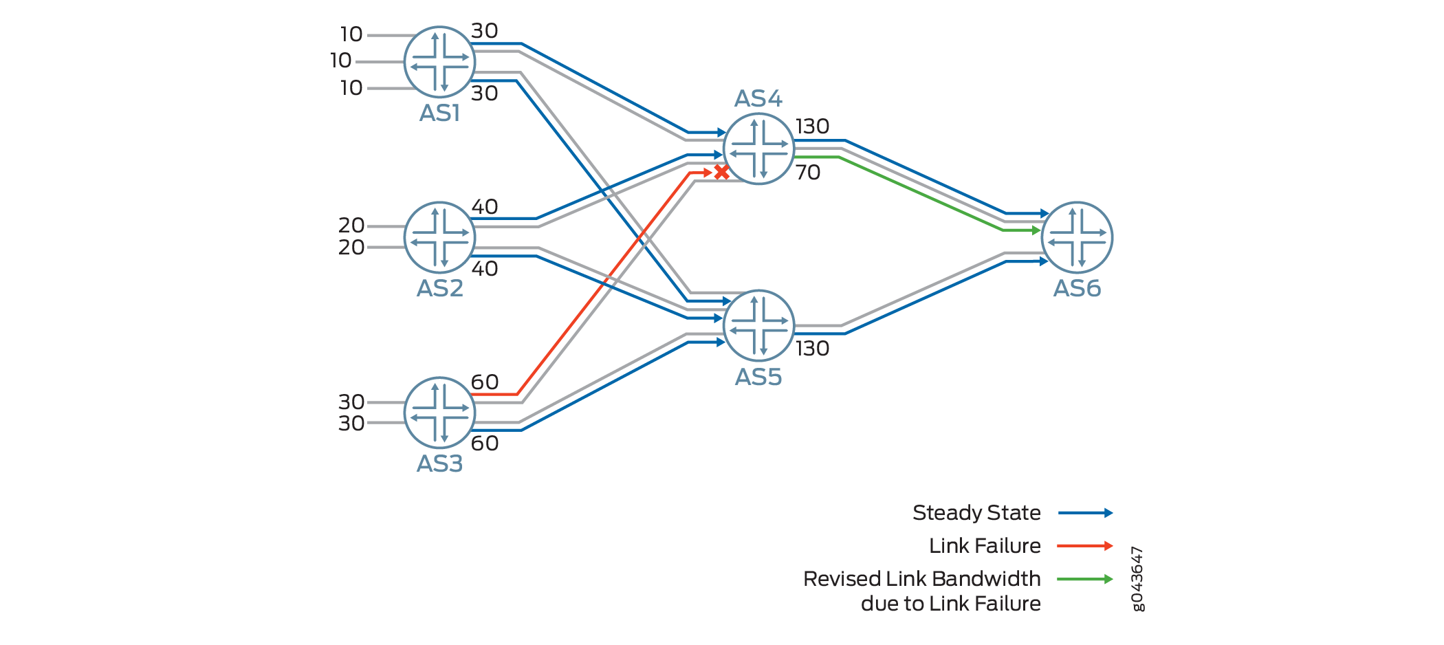
図4では、自律システム1(AS1)は、リモートプレフィックスへの3つのマルチパスルートの帯域幅を集約し、リンク帯域幅拡張コミュニティを使用して30の帯域幅で自律システム4(AS4)にアドバタイズしています。AS3とAS4の間にリンク障害が発生した場合、AS4はAS6にアドバタイズしている帯域幅から60を引き、アドバタイズしていた帯域幅を130から70に変更します。
マルチパスリンクの1つに障害が発生した場合、BGPは、送信リンク帯域幅コミュニティから障害が発生したリンクの帯域幅を差し引いたルートを再アドバタイズします。集約リンク帯域幅が設定された制限値を超えていることが判明した場合、アドバタイズされた集約帯域幅は、2つのピア間で設定されたリンク帯域幅制限値まで切り捨てられます。
BGPピアが、集約帯域幅コミュニティで設定されたマルチパスルートを伝送すると、新しいリンク帯域幅コミュニティには、受信帯域幅コミュニティまたはそのプレフィックスからの帯域幅の合計が追加されます。利用可能なリンク帯域幅は、インターフェースの速度から動的に導き出されます。リンク帯域幅は、推移的拡張コミュニティとして送信されます。
BGPはリンク速度をリモートピアに伝達できるため、ロードバランシングのためのトラフィック分散を最適化できます。BGPグループは、発信または受信、および再アドバタイズされたリンク帯域幅拡張コミュニティに対して、EBGPセッションを介してリンク帯域幅の非推移的拡張コミュニティを送信できます。非推移的リンク帯域幅拡張コミュニティを設定するには:
-
[edit policy-options community name members community-ids]階層レベルのエクスポートポリシーにbandwidth-non-transitive:valueを含めます。 -
[edit protocols bgp group (Protocols BGP) group-name]階層レベルにsend-non-transitive-link-bandwidthオプションを含め、リンク帯域幅コミュニティの場合にのみ、non-transitive-link-bandwidth-extended-communityをEBGPネイバーに送信します。
デバイスがインポート時にルート上のリンク帯域幅コミュニティを自動的に検出して接続できるようにするには、[edit protocols bgp group link-bandwidth]階層レベルにauto-senseステートメントを含めます。この機能により、ネットワーク内で伝送速度が異なるデバイスの統合が容易になり、リンク速度に基づいた効率的なトラフィック配信が可能になります。
関連項目
例:負荷分散のために外部 BGP リンクに集合帯域幅をアドバタイズするポリシーの設定
この例では、ロードバランシングのために外部BGPリンクに集合帯域幅をアドバタイズするポリシーを設定し、設定された集合帯域幅に閾値を指定する方法を示しています。BGPは、マルチパスの利用可能なリンク帯域幅を合計し、集合帯域幅を算出します。リンク障害が発生した場合は、利用可能な帯域幅の現在のステータスを反映して、集約された帯域幅が調整されます。
要件
この例では、以下のハードウェアおよびソフトウェアコンポーネントを使用しています。
-
ロードバランシング機能を備えたルーター4台
-
すべてのデバイスで実行されている Junos OS リリース 17.4 以降
概要
Junos OSリリース17.4R1以降、内部ピアから複数のパスを受信するBGPスピーカーは、これらのパス間でトラフィックを負荷分散します。以前の Junos OS リリースでは、内部ピアから複数のパスを受信する BGPスピーカーは、アクティブなルートに関連付けられたリンク帯域幅のみをアドバタイズしていました。BGPは、マルチパスをタグ付けするために、集合帯域幅を持つ新しいリンク帯域幅拡張コミュニティを使用し、これらの複数のルートの集合帯域幅をDMZリンクにアドバタイズします。集約された複数のルートをアドバタイズするには、[edit policy-options policy-statement name then]階層レベルでaggregate-bandwidthおよびlimit bandwidthアクションを持つポリシーを設定します。
トポロジー
 のために外部BGPリンクに集合帯域幅をアドバタイズするポリシーの設定
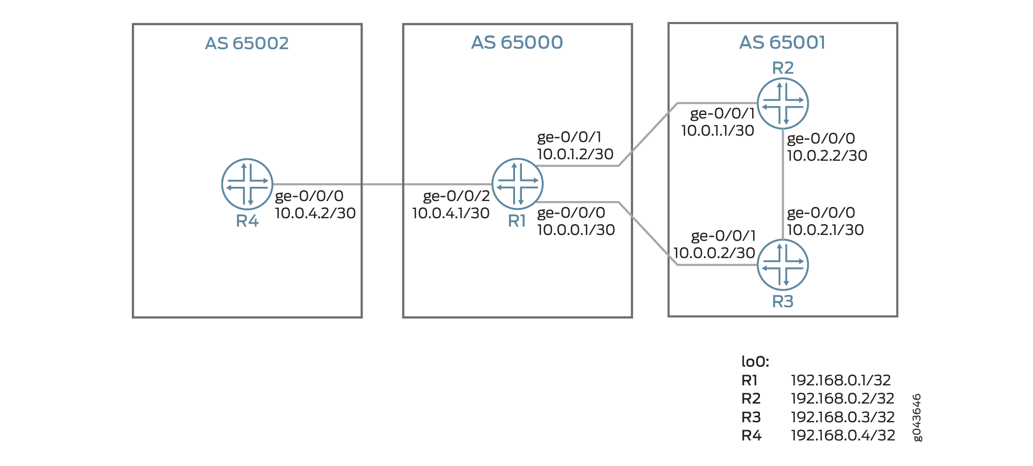
図5では、ルーターR1は、ルーターR2のネクストホップ10.0.1.1を介して、60,000,000バイト/秒、およびルーターR3の10.0.0.2を介して40,000,000バイト/秒で、リモートの宛先へのトラフィックを負荷分散しています。ルーターR1は、宛先10.0.2.0をルーターR4にアドバタイズします。ルーターR1は、利用可能な帯域幅の総量を計算します。これは10000000バイト/秒です。しかし、ルーターR1に設定されたポリシーでは、集合帯域幅の閾値を80,000,000バイト/秒に設定します。そのため、R1 は 1 秒間に 10,000,000 バイトではなく、80,000,000 バイト/秒をアドバタイズします。
マルチパスリンクの1つがダウンした場合、障害が発生したリンクの帯域幅は、BGPネイバーにアドバタイズされる集合帯域幅には追加されません。
設定
CLIクイックコンフィグレーション
この例をすばやく設定するには、以下のコマンドをコピーしてテキストファイルに貼り付け、改行を削除し、ネットワーク設定に一致させる必要がある詳細情報を変更し、コマンドを [edit] 階層レベルでCLIにコピーアンドペーストして、設定モードから commit を入力します。
ルーターR1
set interfaces ge-0/0/0 unit 0 description R1->R3
set interfaces ge-0/0/0 unit 0 family inet address 10.0.0.1/30
set interfaces ge-0/0/1 unit 0 description R1->R2
set interfaces ge-0/0/1 unit 0 family inet address 10.0.1.2/30
set interfaces ge-0/0/2 unit 0 description R1->R4
set interfaces ge-0/0/2 unit 0 family inet address 10.0.4.1/30
set interfaces lo0 unit 0 family inet address 192.168.0.1/32
set routing-options autonomous-system 65000
set protocols bgp group external type external
set protocols bgp group external import bw-dis
set protocols bgp group external peer-as 65001
set protocols bgp group external multipath
set protocols bgp group external neighbor 10.0.1.1
set protocols bgp group external neighbor 10.0.0.2
set protocols bgp group external2 type external
set protocols bgp group external2 peer-as 65002
set policy-options policy-statement bw-dis term a from protocol bgp
set policy-options policy-statement bw-dis term a from neighbor 10.0.1.1
set policy-options policy-statement bw-dis term a then community add bw-high
set policy-options policy-statement bw-dis term a then accept
set policy-options policy-statement bw-dis term b from protocol bgp
set policy-options policy-statement bw-dis term b from neighbor 10.0.0.2
set policy-options policy-statement bw-dis term b then community add bw-low
set policy-options policy-statement bw-dis term b then accept
set policy-options policy-statement aggregate_bw_and_limit_capacity then aggregate-bandwidth
set policy-options policy-statement aggregate_bw_and_limit_capacity then limit-bandwidth 80000000
set policy-options policy-statement aggregate_bw_and_limit_capacity then accept
set protocols bgp group external2 neighbor 10.0.4.2 export aggregate_bw_and_limit_capacity
set policy-options policy-statement loadbal from route-filter 10.0.0.0/16 orlonger
set policy-options policy-statement loadbal then load-balance per-packet
set routing-options forwarding-table export loadbal
set policy-options community bw-high members bandwidth:65000:60000000
set policy-options community bw-low members bandwidth:65000:40000000
ルーターR2
set interfaces ge-0/0/0 unit 0 description R2->R3
set interfaces ge-0/0/0 unit 0 family inet address 10.0.2.2/30
set interfaces ge-0/0/0 unit 0 family iso
set interfaces ge-0/0/1 unit 0 description R2->R1
set interfaces ge-0/0/1 unit 0 family inet address 10.0.1.1/30
set interfaces lo0 unit 0 family inet address 192.168.0.2/32
set interfaces lo0 unit 0 family iso address 49.0001.1921.6800.0002.00
set routing-options static route 172.16.0.0/16 discard
set routing-options static route 172.16.0.0/16 no-install
set routing-options autonomous-system 65001
set protocols bgp group external type external
set protocols bgp group external export bgp-default
set protocols bgp group external export send-direct
set protocols bgp group external peer-as 65000
set protocols bgp group external multipath
set protocols bgp group external neighbor 10.0.1.2
set protocols isis interface ge-0/0/0.0
set protocols isis interface lo0.0
set policy-options policy-statement bgp-default from protocol static
set policy-options policy-statement bgp-default from route-filter 172.16.0.0/16 exact
set policy-options policy-statement bgp-default then accept
set policy-options policy-statement send-direct term 1 from protocol direct
set policy-options policy-statement send-direct term 1 then accept
ルーターR3
set interfaces ge-0/0/0 description R3->R2
set interfaces ge-0/0/0 unit 0 family inet address 10.0.2.1/30
set interfaces ge-0/0/0 unit 0 family iso
set interfaces ge-0/0/1 unit 0 description R3->R1
set interfaces ge-0/0/1 unit 0 family inet address 10.0.0.2/30
set interfaces lo0 unit 0 family inet address 192.168.0.3/32
set interfaces lo0 unit 0 family iso address 49.0001.1921.6800.0003.00
set routing-options static route 172.16.0.0/16 discard
set routing-options static route 172.16.0.0/16 no-install
set routing-options autonomous-system 65001
set protocols bgp group external type external
set protocols bgp group external export bgp-default
set protocols bgp group external export send-direct
set protocols bgp group external peer-as 65000
set protocols bgp group external multipath
set protocols bgp group external neighbor 10.0.0.1
set protocols isis interface ge-0/0/0.0
set protocols isis interface lo0.0
set policy-options policy-statement bgp-default from protocol static
set policy-options policy-statement bgp-default from route-filter 172.16.0.0/16 exact
set policy-options policy-statement bgp-default then accept
set policy-options policy-statement send-direct term 1 from protocol direct
set policy-options policy-statement send-direct term 1 then accept
ルーターR4
set interfaces ge-0/0/0 unit 0 description R4->R1
set interfaces ge-0/0/0 unit 0 family inet address 10.0.4.2/30
set interfaces lo0 unit 0 family inet address 192.168.0.4/32
set routing-options autonomous-system 65002
set protocols bgp group external type external
set protocols bgp group external peer-as 65000
set protocols bgp group external neighbor 10.0.4.1
R1 以降のルーターの設定
ステップバイステップの手順
次の例では、設定階層内のさまざまなレベルに移動する必要があります。CLIのナビゲーションについては、『CLIユーザーガイド』の「設定モードでのCLIエディターの使用」を参照してください。
BGPピア(ルーターR1以降)に集約された帯域幅をアドバタイズするポリシーを設定するには:
ルーター R2、R3、R4 では、適切なインターフェイス名、アドレス、およびその他のパラメーターを変更した後、この手順を繰り返します。
-
インターフェイスにIPv4アドレスを設定します。
>[edit interfaces]
user@R1# set ge-0/0/0 unit 0 description R1->R3
user@R1# set ge-0/0/0 unit 0 family inet address 10.0.0.1/30
user@R1# set ge-0/0/1 unit 0 description R1->R2
user@R1# set ge-0/0/1 unit 0 family inet address 10.0.1.2/30
user@R1# set ge-0/0/2 unit 0 description R1->R4
user@R1# set ge-0/0/2 unit 0 family inet address 10.0.4.1/30
-
ループバックアドレスを設定します。
[edit interfaces]
user@R1# set lo0 unit 0 family inet address 192.168.0.1/32
-
BGPホストの自律システムを設定します。
[edit routing-options]
user@R1# set autonomous-system 65000
-
外部エッジルーターに EBGP を設定します。
[edit protocols]
user@R1# set bgp group external type external
user@R1# set bgp group external import bw-dis
user@R1# set bgp group external peer-as 65001
user@R1# set bgp group external multipath
user@R1# set bgp group external neighbor 10.0.1.1
user@R1# set bgp group external neighbor 10.0.0.2
user@R1# set bgp group external2 type external
user@R1# set bgp group external2 peer-as 65002
-
ルーター R3 を宛先とするトラフィックに高帯域幅コミュニティを割り当てるための帯域幅分配ポリシーを定義します。
[edit policy-options]
user@R1# set policy-statement bw-dis term a from protocol bgp
user@R1# set policy-statement bw-dis term a from neighbor 10.0.1.1
user@R1# set policy-statement bw-dis term a then community add bw-high
user@R1# set policy-statement bw-dis term a then accept
-
ルータ R2 を宛先とするトラフィックに低帯域コミュニティを割り当てるための帯域幅分配ポリシーを定義します。
[edit policy-options]
user@R1# set policy-statement bw-dis term b from protocol bgp
user@R1# set policy-statement bw-dis term b from neighbor 10.0.0.2
user@R1# set policy-statement bw-dis term b then community add bw-low
user@R1# set policy-statement bw-dis term b then accept
-
この機能を有効にして、80,000,000バイトの集合帯域幅を、BGPセッションを介してEBGPピアルーターR4にアドバタイズします。
[edit policy-options]
user@R1# set policy-statement aggregate_bw_and_limit_capacity then aggregate-bandwidth
user@R1# set policy-statement aggregate_bw_and_limit_capacity then limit-bandwidth 80000000
user@R1# set policy-statement aggregate_bw_and_limit_capacity then accept
-
EBGPグループ
external2にaggregate_bw_and limit_capacityポリシーを適用します。[edit protocols] user@R1# set bgp group external2 neighbor 10.0.4.2 export aggregate_bw_and_limit_capacity
-
ロードバランシングポリシーを定義します。
[edit policy-options]
user@R1# set policy-statement loadbal from route-filter 10.0.0.0/16 orlonger
user@R1# set policy-statement loadbal then load-balance per-packet
-
ロードバランシングポリシーを適用します。
[edit routing-options]
user@R1# set forwarding-table export loadbal
-
BGP コミュニティメンバーを設定します。最初の16ビット数は、ローカル自律システムを表しています。2 番目の 32 ビット数は、リンク帯域幅をバイト/秒で表しています。1 Gbps リンクの 60% を使用する
bw-highコミュニティと、1 Gbps リンクの 40% を使用する別のコミュニティbw-lowを設定します。1Gbpsのリンクの60%を高帯域幅コミュニティに設定し、40%を低帯域幅コミュニティに設定します。
[edit policy-options]
user@R1# set community bw-high members bandwidth:65000:60000000
user@R1# set community bw-low members bandwidth:65000:40000000
結果
設定モードから、 show interfaces、 show protocols、 show routing-options、および show policy-options コマンドを入力して設定を確認します。出力に意図した設定が表示されない場合は、この例の手順を繰り返して設定を修正します。
[edit]
user@R1# show interfaces
interfaces {
    ge-0/0/0 {
        unit 0 {
            description R1->R3;
            family inet {
                address 10.0.0.1/30;
            }
        }
    }
    ge-0/0/1 {
        unit 0 {
            description R1->R2;
            family inet {
                address 10.0.1.2/30;
            }
        }
    }
    ge-0/0/2 {
        unit 0 {
            description R1->R4;
            family inet {
                address 10.0.4.1/30;
            }
        }
    }
    lo0 {
        unit 0 {
            family inet {
                address 192.168.0.1/32;
            }
        }
    }
}
[edit]
user@R1# show protocols
protocols {
    bgp {
        group external {
            type external;
            import bw-dis;
            peer-as 65001;
            multipath;
            neighbor 10.0.1.1;
            neighbor 10.0.0.2;
        }
        group external2 {
            type external;
            peer-as 65002;
            neighbor 10.0.4.2 {
                export aggregate_bw_and_limit_capacity;
            }
        }
    }
}
[edit]
user@R1# show routing-options
routing-options {
    autonomous-system 65000;
    forwarding-table {
        export loadbal;
    }
}
[edit]
user@R1# show policy-options
policy-options {
    policy-statement bw-dis {
        term a {
            from {
                protocol bgp;
                neighbor 10.0.1.1;
            }
            then {
                community add bw-high;
                accept;
            }
        }
        term b {
            from {
                protocol bgp;
                neighbor 10.0.0.2;
            }
            then {
                community add bw-low;
                accept;
            }
        }
    }
    policy-statement aggregate_bw_and_limit_capacity {
        then {
            aggregate-bandwidth;
            limit-bandwidth 80000000;
            accept;
        }
    }
    policy-statement loadbal {
        from {
            route-filter 10.0.0.0/16 orlonger;
        }
        then {
            load-balance per-packet;
        }
    }
    community bw-high members bandwidth:65000:60000000;
    community bw-low members bandwidth:65000:40000000;
}
検証
BGPセッションが確立されたことを確認する
目的
BGPピアリングが完了し、ルーター間でBGPセッションが確立されていることを確認するには、次の手順に従います。
アクション
user@R1> show bgp summary
Groups: 2 Peers: 3 Down peers: 0
Table          Tot Paths  Act Paths Suppressed    History Damp State    Pending
inet.0
                      12          8          0          0          0          0
Peer                     AS      InPkt     OutPkt    OutQ   Flaps Last Up/Dwn State|#Active/Received/Accepted/Damped...
10.0.0.2              65001        153        149       0       0     1:07:23 4/6/6/0            0/0/0/0
10.0.1.1              65001        229        226       0       0     1:41:44 4/6/6/0            0/0/0/0
10.0.4.2              65002       1227       1227       0       0     9:10:27 0/0/0/0            0/0/0/0
意味
ルーター R1 は、ルーター R2、R3、および R4 とのピアリングを完了しました。
各パスに集合帯域幅が存在することの検証
目的
各ルートパスに拡張コミュニティが存在することを確認するには、次の手順に従います。
アクション
動作モードから、 show route protocol bgp detail コマンドを実行します。
user@R1> show route 10.0.2.0 protocol bgp detail
inet.0: 20 destinations, 26 routes (20 active, 0 holddown, 0 hidden)
10.0.2.0/30 (2 entries, 1 announced)
        *BGP    Preference: 170/-101
                Next hop type: Router, Next hop index: 0
                Address: 0xb618990
                Next-hop reference count: 3
                Source: 10.0.1.1
                Next hop: 10.0.0.2 via ge-0/0/0.0 balance 40%
                Session Id: 0x0
                Next hop: 10.0.1.1 via ge-0/0/1.0 balance 60%, selected
                Session Id: 0x0
                State: <Active Ext>
                Local AS: 65000 Peer AS: 65001
                Age: 20:33
                Validation State: unverified
                Task: BGP_65001.10.0.1.1
                Announcement bits (3): 0-KRT 2-BGP_Listen.0.0.0.0+179 3-BGP_RT_Background
                AS path: 65001 I
                Communities: bandwidth:65000:60000000
                Accepted Multipath
                Localpref: 100
                Router ID: 128.49.121.137
         BGP    Preference: 170/-101
                Next hop type: Router, Next hop index: 595
                Address: 0xb7a1330
                Next-hop reference count: 9
                Source: 10.0.0.2
                Next hop: 10.0.0.2 via ge-0/0/0.0, selected
                Session Id: 0x141
                State: <NotBest Ext>
                Inactive reason: Not Best in its group - Active preferred
                Local AS: 65000 Peer AS: 65001
                Age: 20:33
                Validation State: unverified
                Task: BGP_65001.10.0.0.2
                AS path: 65001 I
                Communities: bandwidth:65000:40000000
                Accepted MultipathContrib
                Localpref: 100
                Router ID: 128.49.121.132
意味
ルータ R1 が、隣接するルーター R4 に集合帯域幅を広告していることを確認します。
目的
ルーターR1が、外部ネイバーに集合帯域幅をアドバタイズしていることを確認するには、次の手順に従います。
アクション
user@R1> show route advertising-protocol bgp 10.0.4.2 10.0.2.0/30 detail
inet.0: 20 destinations, 26 routes (20 active, 0 holddown, 0 hidden)
* 10.0.2.0/30 (2 entries, 1 announced)
 BGP group external2 type External
     Nexthop: Self
     AS path: [65000] 65001 I
     Communities: bandwidth:65000:80000000
意味
ルーターR1は、80,000,000バイトの集合帯域幅をネイバーにアドバタイズしています。
BGPにおける単一宛先への複数パスのアドバタイズを理解する
BGPピアは、アップデートメッセージで互いにルートをアドバタイズします。BGPは、Junos OSルーティングテーブル(inet.0)にルートを保存します。ルーティングテーブルの各プレフィックスに対して、ルーティングプロトコルプロセスはアクティブパスと呼ばれる単一の最良のパスを選択します。同じ宛先への複数のパスをアドバタイズするように BGP を設定しない限り、BGP はアクティブなパスのみをアドバタイズします。
宛先へのアクティブなパスのみを広告する代わりに、宛先への複数のパスを広告するように BGP を設定できます。自律システム(AS)内では、目的地に到達するための出口を複数用意することで、以下のようなメリットがあります:
耐障害性-パスの多様性により、障害発生後の復旧時間を短縮できます。例えば、同じ宛先への複数のパスを受信したボーダーは、バックアップパスを事前に計算し、プライマリパスが無効になったときにボーダールーティングデバイスがバックアップを使用して迅速に接続を復元できるように準備しておくことができます。バックアップパスがない場合、復旧時間はBGP再コンバージェンスに依存し、新しい最適なパスを学習できるようになるまで、ネットワーク内の撤退およびアドバタイズメッセージが含まれます。
負荷分散—AS内のルーティングが一定の制約を満たす場合、同じ宛先に到達する複数のパスが利用可能なため、トラフィックのロードバランシングが可能になります。
メンテナンス-代替の出口を利用できるため、ルーターの正常なメンテナンス運用が可能になります。
BGPで複数のルートをアドバタイズする場合、以下の制限が適用されます。
-
サポートされるファミリのアドレス:
-
IPv4 ユニキャスト(
family inet unicast) -
IPv6 ユニキャスト(
family inet6 unicast) -
IPv4ラベル付きユニキャスト(
family inet labeled-unicast) -
IPv6ラベル付きユニキャスト(
family inet6 labeled-unicast) -
IPv4 VPNユニキャスト(
family inet-vpn unicast) -
IPv6 VPNユニキャスト(
family inet6-vpn unicast)
次の例は、IPv4 VPNユニキャストファミリとIPv6 VPNユニキャストファミリの設定を示しています。
bgp { group <group-name> { family inet-vpn unicast { add-path { send { include-backup-path include-backup-path; multipath; path-count path-count; path-selection-mode { (all-paths | equal-cost-paths); } prefix-policy [ policy-names ... ]; } receive; } family inet6-vpn unicast { add-path { send { include-backup-path include-backup-path; multipath; path-count path-count; path-selection-mode { (all-paths | equal-cost-paths); } prefix-policy [ policy-names ... ]; } receive; } } } -
-
内部BGP(IBGP)および外部BGP(EBGP)ピアの
add-pathをサポートします。注:-
IBGPおよびEBGPピアでは add-pathreceive をサポートします。
-
IBGPピアでは、add-pathsendのみをサポートします。
-
EBGPピアでは、 add-pathsend send はサポートされていません。EBGPピアで add-pathsend の設定をコミットしようとすると、CLIはコミットエラーをスローします。
-
-
マスターインスタンスのみです。ルーティングインスタンスはサポートされていません。
-
グレースフル リスタートとノンストップ アクティブ ルーティング(NSR)がサポートされています。
-
BGP監視プロトコル(BMP)をサポートしていません。
-
プレフィックス・ポリシーは、宛先への複数のパスをアドバタイズするように設定されたルーター上で、ルートをフィルタリングすることができます。プレフィックス ポリシーは、プレフィックスにのみ一致できます。ルートの属性を一致させることも、ルートの属性を変更することもできません。
Junos OSリリース18.4R1以降、BGPは複数のECMPパスに加えて、最大2つのアドパスルートをアドバタイズできます。
最大64個のアドパス、またはイコールコストパスのみをアドバタイズするには、[edit protocols bgp group group-name family name addpath send]階層レベルでpath-selection-modeを含めます。multipathとpath-selection-modeの両方を同時に有効にすることはできません。
関連項目
例:BGP における複数パスのアドバタイズ
この例では、BGPルーターはアクティブなパスのみをアドバタイズするのではなく、複数のパスをアドバタイズするように設定されています。BGPにおける複数パスのアドバタイズについては、RFC 7911、 BGPにおける複数パスのアドバタイズに記載されています。
要件
この例では、以下のハードウェアおよびソフトウェアコンポーネントを使用しています。
8 台の BGP 対応デバイス。
BGP対応デバイスのうち5台は、必ずしもルーターである必要はありません。例えば、EXシリーズのイーサネットスイッチなどです。
BGP対応デバイスのうち3台は、複数パスの送信または複数パスの受信(または複数パスの送信と受信の両方)を行うように設定されています。これら 3 つの BGP 対応デバイスは、M Series マルチサービス エッジ ルーター、MXシリーズ 5G ユニバーサルルーティングプラットフォーム、または T Series コア ルーターである必要があります。
3台のルーターは、Junos OSリリース11.4以降を実行している必要があります。
概要
宛先への複数のパスを設定するには、以下のステートメントを使用します。
[edit protocols bgp group group-name family family]
add-path {
    receive;
    send {
        include-backup-path include-backup-path;
        multipath;
        path-count path-count;
        path-selection-mode {
            (all-paths | equal-cost-paths);
        }
        prefix-policy [ policy-names ... ];
    }
}
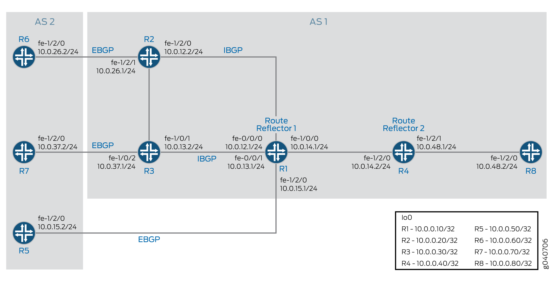
この例では、ルーター R5、ルーター R6、ルーター R7 が静的ルートを BGP に再分配しています。ルーター R1 とルーター R4 はルート リフレクタです。ルーター R2 とルーター R3 はルートリフレクタ R1 のクライアントです。ルーター R8 は、ルート リフレクタ R4 のクライアントです。
BGPでマルチパスアドバタイズメントが有効な場合、ルートリフレクションはオプションです。
add-path send path-count 6設定では、ルーター R1 はルーター R4 に最大 6 つのパス(宛先ごと)を送信するように構成されています。
add-path receive設定では、ルーターR4はルーターR1から複数のパスを受信するように構成されています。
add-path send path-count 6設定では、ルーター R4 はルーター R8 に最大 6 本のパスを送信するように構成されています。
add-path receive設定では、ルーター R8 はルーター R4 から複数のパスを受信するように構成されています。
add-path send prefix-policy allow_199ポリシー設定(対応するルート フィルターとともに)は、ルーター R4 が 172.16.199.1/32 ルートのみに対して複数のパスを送信することを制限しています。
設定
- CLIクイックコンフィグレーション
- ルーターR1の設定
- ルーターR2の設定
- ルーターR3の設定
- ルーターR4の設定
- ルーターR5の設定
- ルーターR6の設定
- ルーターR7の設定
- ルーターR8の設定
- 結果
CLIクイックコンフィグレーション
この例をすばやく設定するには、以下のコマンドをコピーしてテキストファイルに貼り付け、改行を削除して、ネットワーク構成に合わせて必要な詳細を変更してから、コマンドを [edit] 階層レベルのCLIにコピー&ペーストします。
ルーターR1
set interfaces fe-0/0/0 unit 12 family inet address 10.0.12.1/24
set interfaces fe-0/0/1 unit 13 family inet address 10.0.13.1/24
set interfaces fe-1/0/0 unit 14 family inet address 10.0.14.1/24
set interfaces fe-1/2/0 unit 15 family inet address 10.0.15.1/24
set interfaces lo0 unit 10 family inet address 10.0.0.10/32
set protocols bgp group rr type internal
set protocols bgp group rr local-address 10.0.0.10
set protocols bgp group rr cluster 10.0.0.10
set protocols bgp group rr neighbor 10.0.0.20
set protocols bgp group rr neighbor 10.0.0.30
set protocols bgp group e1 type external
set protocols bgp group e1 neighbor 10.0.15.2 local-address 10.0.15.1
set protocols bgp group e1 neighbor 10.0.15.2 peer-as 2
set protocols bgp group rr_rr type internal
set protocols bgp group rr_rr local-address 10.0.0.10
set protocols bgp group rr_rr neighbor 10.0.0.40 family inet unicast add-path send path-count 6
set protocols ospf area 0.0.0.0 interface lo0.10 passive
set protocols ospf area 0.0.0.0 interface fe-0/0/0.12
set protocols ospf area 0.0.0.0 interface fe-0/0/1.13
set protocols ospf area 0.0.0.0 interface fe-1/0/0.14
set protocols ospf area 0.0.0.0 interface fe-1/2/0.15
set routing-options router-id 10.0.0.10
set routing-options autonomous-system 1
ルーターR2
set interfaces fe-1/2/0 unit 21 family inet address 10.0.12.2/24
set interfaces fe-1/2/1 unit 26 family inet address 10.0.26.1/24
set interfaces lo0 unit 20 family inet address 10.0.0.20/32
set protocols bgp group rr type internal
set protocols bgp group rr local-address 10.0.0.20
set protocols bgp group rr neighbor 10.0.0.10 export set_nh_self
set protocols bgp group e1 type external
set protocols bgp group e1 neighbor 10.0.26.2 peer-as 2
set protocols ospf area 0.0.0.0 interface lo0.20 passive
set protocols ospf area 0.0.0.0 interface fe-1/2/0.21
set protocols ospf area 0.0.0.0 interface fe-1/2/1.28
set policy-options policy-statement set_nh_self then next-hop self
set routing-options autonomous-system 1
ルーターR3
set interfaces fe-1/0/1 unit 31 family inet address 10.0.13.2/24
set interfaces fe-1/0/2 unit 37 family inet address 10.0.37.1/24
set interfaces lo0 unit 30 family inet address 10.0.0.30/32
set protocols bgp group rr type internal
set protocols bgp group rr local-address 10.0.0.30
set protocols bgp group rr neighbor 10.0.0.10 export set_nh_self
set protocols bgp group e1 type external
set protocols bgp group e1 neighbor 10.0.37.2 peer-as 2
set protocols ospf area 0.0.0.0 interface lo0.30 passive
set protocols ospf area 0.0.0.0 interface fe-1/0/1.31
set protocols ospf area 0.0.0.0 interface fe-1/0/2.37
set policy-options policy-statement set_nh_self then next-hop self
set routing-options autonomous-system 1
ルーターR4
set interfaces fe-1/2/0 unit 41 family inet address 10.0.14.2/24
set interfaces fe-1/2/1 unit 48 family inet address 10.0.48.1/24
set interfaces lo0 unit 40 family inet address 10.0.0.40/32
set protocols bgp group rr type internal
set protocols bgp group rr local-address 10.0.0.40
set protocols bgp group rr family inet unicast add-path receive
set protocols bgp group rr neighbor 10.0.0.10
set protocols bgp group rr_client type internal
set protocols bgp group rr_client local-address 10.0.0.40
set protocols bgp group rr_client cluster 10.0.0.40
set protocols bgp group rr_client neighbor 10.0.0.80 family inet unicast add-path send path-count 6
set protocols bgp group rr_client neighbor 10.0.0.80 family inet unicast add-path send prefix-policy allow_199
set protocols ospf area 0.0.0.0 interface fe-1/2/0.41
set protocols ospf area 0.0.0.0 interface lo0.40 passive
set protocols ospf area 0.0.0.0 interface fe-1/2/1.48
set policy-options policy-statement allow_199 from route-filter 172.16.199.1/32 exact
set policy-options policy-statement allow_199 term match_199 from prefix-list match_199
set policy-options policy-statement allow_199 then add-path send-count 20
set policy-options policy-statement allow_199 then accept
set routing-options autonomous-system 1
ルーターR5
set interfaces fe-1/2/0 unit 51 family inet address 10.0.15.2/24
set interfaces lo0 unit 50 family inet address 10.0.0.50/32
set protocols bgp group e1 type external
set protocols bgp group e1 neighbor 10.0.15.1 export s2b
set protocols bgp group e1 neighbor 10.0.15.1 peer-as 1
set policy-options policy-statement s2b from protocol static
set policy-options policy-statement s2b from protocol direct
set policy-options policy-statement s2b then as-path-expand 2
set policy-options policy-statement s2b then accept
set routing-options autonomous-system 2
set routing-options static route 172.16.199.1/32 reject
set routing-options static route 172.16.198.1/32 reject
ルーターR6
set interfaces fe-1/2/0 unit 62 family inet address 10.0.26.2/24
set interfaces lo0 unit 60 family inet address 10.0.0.60/32
set protocols bgp group e1 type external
set protocols bgp group e1 neighbor 10.0.26.1 export s2b
set protocols bgp group e1 neighbor 10.0.26.1 peer-as 1
set policy-options policy-statement s2b from protocol static
set policy-options policy-statement s2b from protocol direct
set policy-options policy-statement s2b then accept
set routing-options autonomous-system 2
set routing-options static route 172.16.199.1/32 reject
set routing-options static route 172.16.198.1/32 reject
ルーターR7
set interfaces fe-1/2/0 unit 73 family inet address 10.0.37.2/24
set interfaces lo0 unit 70 family inet address 10.0.0.70/32
set protocols bgp group e1 type external
set protocols bgp group e1 neighbor 10.0.37.1 export s2b
set protocols bgp group e1 neighbor 10.0.37.1 peer-as 1
set policy-options policy-statement s2b from protocol static
set policy-options policy-statement s2b from protocol direct
set policy-options policy-statement s2b then accept
set routing-options autonomous-system 2
set routing-options static route 172.16.199.1/32 reject
ルーターR8
set interfaces fe-1/2/0 unit 84 family inet address 10.0.48.2/24
set interfaces lo0 unit 80 family inet address 10.0.0.80/32
set protocols bgp group rr type internal
set protocols bgp group rr local-address 10.0.0.80
set protocols bgp group rr neighbor 10.0.0.40 family inet unicast add-path receive
set protocols ospf area 0.0.0.0 interface lo0.80 passive
set protocols ospf area 0.0.0.0 interface fe-1/2/0.84
set routing-options autonomous-system 1
ルーターR1の設定
ステップバイステップの手順
次の例では、設定階層のさまざまなレベルに移動する必要があります。CLIのナビゲーションについては、『Junos OS CLIユーザーガイド』の「設定モードでのCLIエディタの使用」を参照してください。
ルーターR1を設定するには:
ルーター R2、ルーター R3、ルーター R4、およびルーター R5 へのインターフェイスを設定し、ループバック(lo0)インターフェイスを設定します。
[edit interfaces]
user@R1# set fe-0/0/0 unit 12 family inet address 10.0.12.1/24
user@R1# set fe-0/0/1 unit 13 family inet address 10.0.13.1/24
user@R1# set fe-1/0/0 unit 14 family inet address 10.0.14.1/24
user@R1# set fe-1/2/0 unit 15 family inet address 10.0.15.1/24
user@R1#set lo0 unit 10 family inet address 10.0.0.10/32
インターフェイスに BGP を設定し、IBGP ルート リフレクションを設定します。
[edit protocols bgp]
user@R1# set group rr type internal
user@R1# set group rr local-address 10.0.0.10
user@R1# set group rr cluster 10.0.0.10
user@R1# set group rr neighbor 10.0.0.20
user@R1# set group rr neighbor 10.0.0.30
user@R1# set group rr_rr type internal
user@R1# set group rr_rr local-address 10.0.0.10
user@R1# set group e1 type external
user@R1# set group e1 neighbor 10.0.15.2 local-address 10.0.15.1
user@R1# set group e1 neighbor 10.0.15.2 peer-as 2
ルーターR1は、隣接するルーターR4に最大6本のパスを送信するように設定します。
パスの宛先は、ルーター R1 が複数のパスを通じて到達できる任意の宛先とすることができます。
[edit protocols bgp]
user@R1# set group rr_rr neighbor 10.0.0.40 family inet unicast add-path send path-count 6
インターフェイスに OSPF を設定します。
[edit protocols ospf]
user@R1# set area 0.0.0.0 interface lo0.10 passive
user@R1# set area 0.0.0.0 interface fe-0/0/0.12
user@R1# set area 0.0.0.0 interface fe-0/0/1.13
user@R1# set area 0.0.0.0 interface fe-1/0/0.14
user@R1# set area 0.0.0.0 interface fe-1/2/0.15
ルーターIDと自律システム番号を設定します。
[edit routing-options]
user@R1# set router-id 10.0.0.10
user@R1# set autonomous-system 1
デバイスの設定が完了したら、設定をコミットします。
user@R1# commit
結果
設定モードから、 show interfaces、 show protocols、 show policy-options、 show routing-options コマンドを入力して設定を確認します。出力に意図した設定が表示されない場合は、この例の手順を繰り返して設定を修正します。
user@R1# show interfaces
fe-0/0/0 {
    unit 12 {
        family inet {
            address 10.0.12.1/24;
        }
    }
}
fe-0/0/1 {
    unit 13 {
        family inet {
            address 10.0.13.1/24;
        }
    }
}
fe-1/0/0 {
    unit 14 {
        family inet {
            address 10.0.14.1/24;
        }
    }
}
fe-1/2/0 {
    unit 15 {
        family inet {
            address 10.0.15.1/24;
        }
    }
}
lo0 {
    unit 10 {
        family inet {
            address 10.0.0.10/32;
        }
    }
}
user@R1# show protocols
bgp {
    group rr {
        type internal;
        local-address 10.0.0.10;
        cluster 10.0.0.10;
        neighbor 10.0.0.20;
        neighbor 10.0.0.30;
    }
    group e1 {
        type external;
        neighbor 10.0.15.2 {
            local-address 10.0.15.1;
            peer-as 2;
        }
    }
    group rr_rr {
        type internal;
        local-address 10.0.0.10;
        neighbor 10.0.0.40 {
            family inet {
                unicast {
                    add-path {
                        send {
                            path-count 6;
                        }
                    }
                }
            }
        }
    }
}
ospf {
    area 0.0.0.0 {
        interface lo0.10 {
            passive;
        }
        interface fe-0/0/0.12;
        interface fe-0/0/1.13;
        interface fe-1/0/0.14;
        interface fe-1/2/0.15;
    }
}
user@R1# show routing-options
router-id 10.0.0.10;
 autonomous-system 1;
ルーターR2の設定
ステップバイステップの手順
ルーターR2を設定するには:
ループバック(lo0)インタフェースとルーター R6、ルーター R1 へのインタフェースを設定します。
[edit interfaces]
user@R2# set fe-1/2/0 unit 21 family inet address 10.0.12.2/24
user@R2# set fe-1/2/1 unit 26 family inet address 10.0.26.1/24
user@R2# set lo0 unit 20 family inet address 10.0.0.20/32
ルーター R2 のインターフェイスに BGP と OSPF を設定します。
[edit protocols]
user@R2# set bgp group rr type internal
user@R2# set bgp group rr local-address 10.0.0.20
user@R2# set bgp group e1 type external
user@R2# set bgp group e1 neighbor 10.0.26.2 peer-as 2
user@R2# set ospf area 0.0.0.0 interface lo0.20 passive
user@R2# set ospf area 0.0.0.0 interface fe-1/2/0.21
user@R2# set ospf area 0.0.0.0 interface fe-1/2/1.28
ルーターR2からルーターR1へ送信されるルートは、ルーターR1が10.0.26.0/24ネットワーク上のルーターR6のアドレスへのルートを持っていないため、ルーターR2をネクストホップとしてアドバタイズしてください。
[edit]
user@R2# set policy-options policy-statement set_nh_self then next-hop self
user@R2# set protocols bgp group rr neighbor 10.0.0.10 export set_nh_self
自律システム番号を設定します。
[edit]
user@R2# set routing-options autonomous-system 1
デバイスの設定が完了したら、設定をコミットします。
user@R2# commit
結果
設定モードから、 show interfaces、 show protocols、 show policy-options、 show routing-options コマンドを入力して設定を確認します。出力に意図した設定が表示されない場合は、この例の手順を繰り返して設定を修正します。
user@R2# show interfaces
fe-1/2/0 {
    unit 21 {
        family inet {
            address 10.0.12.2/24;
        }
    }
}
fe-1/2/1 {
    unit 26 {
        family inet {
            address 10.0.26.1/24;
        }
    }
}
lo0 {
    unit 20 {
        family inet {
            address 10.0.0.20/32;
        }
    }
}
user@R2# show protocols
bgp {
    group rr {
        type internal;
        local-address 10.0.0.20;
        neighbor 10.0.0.10 {
            export set_nh_self;
        }
    }
    group e1 {
        type external;
        neighbor 10.0.26.2 {
            peer-as 2;
        }
    }
}
ospf {
    area 0.0.0.0 {
        interface lo0.20 {
            passive;
        }
        interface fe-1/2/0.21;
        interface fe-1/2/1.28;
    }
}
user@R2# show policy-options
policy-statement set_nh_self {
    then {
        next-hop self;
    }
}
user@R2# show routing-options
 autonomous-system 1;
ルーターR3の設定
ステップバイステップの手順
ルーターR3を設定するには:
ループバック(lo0)インタフェースと、ルーターR7、ルーターR1へのインタフェースを設定します。
[edit interfaces]
user@R3# set fe-1/0/1 unit 31 family inet address 10.0.13.2/24
user@R3# set fe-1/0/2 unit 37 family inet address 10.0.37.1/24
user@R3# set lo0 unit 30 family inet address 10.0.0.30/32
ルーター R3 のインターフェイスに BGP と OSPF を設定します。
[edit protocols]
user@R3# set bgp group rr type internal
user@R3# set bgp group rr local-address 10.0.0.30
user@R3# set bgp group e1 type external
user@R3# set bgp group e1 neighbor 10.0.37.2 peer-as 2
user@R3# set ospf area 0.0.0.0 interface lo0.30 passive
user@R3# set ospf area 0.0.0.0 interface fe-1/0/1.31
user@R3# set ospf area 0.0.0.0 interface fe-1/0/2.37
ルーターR3からルーターR1へ送信されるルートは、ルーターR1が10.0.37.0/24ネットワーク上のルーターR7のアドレスへのルートを持っていないため、ルーターR3をネクストホップとしてアドバタイズしてください。
[edit]
user@R3# set policy-options policy-statement set_nh_self then next-hop self
user@R3# set protocols bgp group rr neighbor 10.0.0.10 export set_nh_self
自律システム番号を設定します。
[edit]
user@R3# set routing-options autonomous-system 1
デバイスの設定が完了したら、設定をコミットします。
user@R3# commit
結果
設定モードから、 show interfaces、 show protocols、 show policy-options、および show routing-options コマンドを入力して設定を確認します。出力に意図した設定が表示されない場合は、この例の手順を繰り返して設定を修正します。
user@R3# show interfaces
fe-1/0/1 {
    unit 31 {
        family inet {
            address 10.0.13.2/24;
        }
    }
}
fe-1/0/2 {
    unit 37 {
        family inet {
            address 10.0.37.1/24;
        }
    }
}
lo0 {
    unit 30 {
        family inet {
            address 10.0.0.30/32;
        }
    }
}
user@R3# show protocols
bgp {
    group rr {
        type internal;
        local-address 10.0.0.30;
        neighbor 10.0.0.10 {
            export set_nh_self;
        }
    }
    group e1 {
        type external;
        neighbor 10.0.37.2 {
            peer-as 2;
        }
    }
}
ospf {
    area 0.0.0.0 {
        interface lo0.30 {
            passive;
        }
        interface fe-1/0/1.31;
        interface fe-1/0/2.37;
    }
}
user@R3# show policy-options
policy-statement set_nh_self {
    then {
        next-hop self;
    }
}
user@R3# show routing-options
 autonomous-system 1;
ルーターR4の設定
ステップバイステップの手順
ルーターR4を設定するには:
ルーター R1 とルーター R8 のインターフェイスを設定し、ループバック(lo0)インターフェイスを設定します。
[edit interfaces]
user@R4# set fe-1/2/0 unit 41 family inet address 10.0.14.2/24
user@R4# set fe-1/2/1 unit 48 family inet address 10.0.48.1/24
user@R4# set lo0 unit 40 family inet address 10.0.0.40/32
インターフェイスに BGP を設定し、IBGP ルート リフレクションを設定します。
[edit protocols bgp]
user@R4# set group rr type internal
user@R4# set group rr local-address 10.0.0.40
user@R4# set group rr neighbor 10.0.0.10
user@R4# set group rr_client type internal
user@R4# set group rr_client local-address 10.0.0.40
user@R4# set group rr_client cluster 10.0.0.40
ルーターR4は、隣接するルーターR8に最大6本のパスを送信するように設定します。
パスの宛先は、ルーターR4が複数のパスを通じて到達できる任意の宛先とすることができます。
[edit protocols bgp]
user@R4# set group rr_client neighbor 10.0.0.80 family inet unicast add-path send path-count 6
ルーターR4は、隣接するルーターR1から複数のパスを受信するように設定します。
パスの宛先は、ルーター R1 が複数のパスを通じて到達できる任意の宛先とすることができます。
[edit protocols bgp group rr family inet unicast]
user@R4# set add-path receive
インターフェイスに OSPF を設定します。
[edit protocols ospf area 0.0.0.0]
user@R4# set interface fe-1/2/0.41
user@R4# set interface lo0.40 passive
user@R4# set interface fe-1/2/1.48
ルーターR4がルーターR8に対して172.16.199.1/32のルートを複数回送信できるようにポリシーを設定します。
ルーターR4は、172.16.198.1/32ルートと172.16.199.1/32ルートで複数のパスを受信します。ただし、このポリシーのため、ルーターR4は172.16.199.1/32ルートに対してのみ複数のパスを送信します。
[edit protocols bgp group rr_client neighbor 10.0.0.80 family inet unicast]
user@R4# set add-path send prefix-policy allow_199
[edit policy-options policy-statement allow_199]
user@R4# set from route-filter 172.16.199.1/32 exact
user@R4# set then accept
ルーターR4は、アドパスアドバタイズされたプレフィックスのサブセットに対して、最大20 BGP
add-pathルートを送信するように設定することもできます。[edit policy-options policy-statement allow_199] user@R4# set term match_199 from prefix-list match_199 user@R4# set then add-path send-count 20
自律システム番号を設定します。
[edit routing-options]
user@R4# set autonomous-system 1
デバイスの設定が完了したら、設定をコミットします。
user@R4# commit
結果
設定モードから、 show interfaces、 show protocols、 show policy-options、 show routing-options コマンドを入力して設定を確認します。出力に意図した設定が表示されない場合は、この例の手順を繰り返して設定を修正します。
user@R4# show interfaces
fe-1/2/0 {
    unit 41 {
        family inet {
            address 10.0.14.2/24;
        }
    }
}
fe-1/2/1 {
    unit 48 {
        family inet {
            address 10.0.48.1/24;
        }
    }
}
lo0 {
    unit 40 {
        family inet {
            address 10.0.0.40/32;
        }
    }
}
user@R4# show protocols
bgp {
    group rr {
        type internal;
        local-address 10.0.0.40;
        family inet {
            unicast {
                add-path {
                    receive;
                }
            }
        }
        neighbor 10.0.0.10;
    }
    group rr_client {
        type internal;
        local-address 10.0.0.40;
        cluster 10.0.0.40;
        neighbor 10.0.0.80 {
            family inet {
                unicast {
                    add-path {
                        send {
                            path-count 6;
                            prefix-policy allow_199;
                        }
                    }
                }
            }
        }
    }
}
ospf {
    area 0.0.0.0 {
        interface lo0.40 {
            passive;
        }
        interface fe-1/2/0.41;
        interface fe-1/2/1.48;
    }
}
user@R4# show policy-options
policy-statement allow_199 {
    from {
        route-filter 172.16.199.1/32 exact;
    }
    from term match_199 {
        prefix-list match_199;
    }
        then add-path send-count 20;
    then accept;
}
user@R4# show routing-options
 autonomous-system 1;
ルーターR5の設定
ステップバイステップの手順
ルーターR5を設定するには:
ループバック(lo0)インタフェースとルーターR1へのインタフェースを設定します。
[edit interfaces]
user@R5# set fe-1/2/0 unit 51 family inet address 10.0.15.2/24
user@R5# set lo0 unit 50 family inet address 10.0.0.50/32
ルーターR5のインタフェースにBGPを設定します。
[edit protocols bgp group e1]
user@R5# set type external
user@R5# set neighbor 10.0.15.1 peer-as 1
BGPに再配布するためのスタティックルートを作成します。
[edit routing-options]
user@R5# set static route 172.16.199.1/32 reject
user@R5# set static route 172.16.198.1/32 reject
スタティックルートとダイレクトルートをBGPに再分配します。
[edit protocols bgp group e1 neighbor 10.0.15.1]
user@R5# set export s2b
[edit policy-options policy-statement s2b]
user@R5# set from protocol static
user@R5# set from protocol direct
user@R5# set then as-path-expand 2
user@R5# set then accept
自律システム番号を設定します。
[edit routing-options]
user@R5# set autonomous-system 2
デバイスの設定が完了したら、設定をコミットします。
user@R5# commit
結果
設定モードから、 show interfaces、 show protocols、 show policy-options、および show routing-options コマンドを入力して設定を確認します。出力に意図した設定が表示されない場合は、この例の手順を繰り返して設定を修正します。
user@R5# show interfaces
fe-1/2/0 {
    unit 51 {

        family inet {
            address 10.0.15.2/24;
        }
    }
}
lo0 {
    unit 50 {
        family inet {
            address 10.0.0.50/32;
        }
    }
}
user@R5# show protocols
bgp {
    group e1 {
        type external;
        neighbor 10.0.15.1 {
            export s2b;
            peer-as 1;
        }
    }
}
user@R5# show policy-options
policy-statement s2b {
    from protocol [ static direct ];
    then {
        as-path-expand 2;
        accept;
    }
}
user@R5# show routing-options
static {
    route 172.16.198.1/32 reject;
    route 172.16.199.1/32 reject;
}
 autonomous-system 2;
ルーターR6の設定
ステップバイステップの手順
ルーターR6を設定するには:
ループバック(lo0)インタフェースとルーターR2へのインタフェースを設定します。
[edit interfaces]
user@R6# set fe-1/2/0 unit 62 family inet address 10.0.26.2/24
user@R6# set lo0 unit 60 family inet address 10.0.0.60/32
ルーターR6のインタフェースにBGPを設定します。
[edit protocols]
user@R6# set bgp group e1 type external
user@R6# set bgp group e1 neighbor 10.0.26.1 peer-as 1
BGPに再配布するためのスタティックルートを作成します。
[edit]
user@R6# set routing-options static route 172.16.199.1/32 reject
user@R6# set routing-options static route 172.16.198.1/32 reject
ルーターR6のルーティングテーブルからスタティックルートとダイレクトルートをBGPに再分配します。
[edit protocols bgp group e1 neighbor 10.0.26.1]
user@R6# set export s2b
[edit policy-options policy-statement s2b]
user@R6# set from protocol static
user@R6# set from protocol direct
user@R6# set then accept
自律システム番号を設定します。
[edit routing-options]
user@R6# set autonomous-system 2
デバイスの設定が完了したら、設定をコミットします。
user@R6# commit
結果
設定モードから、 show interfaces、 show protocols、 show policy-options、および show routing-options コマンドを入力して設定を確認します。出力に意図した設定が表示されない場合は、この例の手順を繰り返して設定を修正します。
user@R6# show interfaces
fe-1/2/0 {
    unit 62 {

        family inet {
            address 10.0.26.2/24;
        }
    }
}
lo0 {
    unit 60 {
        family inet {
            address 10.0.0.60/32;
        }
    }
}
user@R6# show protocols
bgp {
    group e1 {
        type external;
        neighbor 10.0.26.1 {
            export s2b;
            peer-as 1;
        }
    }
}
user@R6# show policy-options
policy-statement s2b {
    from protocol [ static direct ];
    then accept;
}
user@R6# show routing-options
static {
    route 172.16.198.1/32 reject;
    route 172.16.199.1/32 reject;
}
 autonomous-system 2;
ルーターR7の設定
ステップバイステップの手順
ルーターR7を設定するには:
ループバック(lo0)インタフェースとルーターR3へのインタフェースを設定します。
[edit interfaces]
user@R7# set fe-1/2/0 unit 73 family inet address 10.0.37.2/24
user@R7# set lo0 unit 70 family inet address 10.0.0.70/32
ルーターR7のインタフェースにBGPを設定します。
[edit protocols bgp group e1]
user@R7# set type external
user@R7# set neighbor 10.0.37.1 peer-as 1
BGPに再配布するためのスタティックルートを作成します。
[edit]
user@R7# set routing-options static route 172.16.199.1/32 reject
ルーターR7のルーティングテーブルからスタティックルートとダイレクトルートをBGPに再分配します。
[edit protocols bgp group e1 neighbor 10.0.37.1]
user@R7# set export s2b
[edit policy-options policy-statement s2b]
user@R7# set from protocol static
user@R7# set from protocol direct
user@R7# set then accept
自律システム番号を設定します。
[edit routing-options]
user@R7# set autonomous-system 2
デバイスの設定が完了したら、設定をコミットします。
user@R7# commit
結果
設定モードから、 show interfaces、 show protocols、 show policy-options、および show routing-options コマンドを入力して設定を確認します。出力に意図した設定が表示されない場合は、この例の手順を繰り返して設定を修正します。
user@R7# show interfaces
fe-1/2/0 {
    unit 73 {

        family inet {
            address 10.0.37.2/24;
        }
    }
}
lo0 {
    unit 70 {
        family inet {
            address 10.0.0.70/32;
        }
    }
}
user@R7# show protocols
bgp {
    group e1 {
        type external;
        neighbor 10.0.37.1 {
            export s2b;
            peer-as 1;
        }
    }
}
user@R7# show policy-options
policy-statement s2b {
    from protocol [ static direct ];
    then accept;
}
user@R7# show routing-options
static {
    route 172.16.199.1/32 reject;
}
 autonomous-system 2;
ルーターR8の設定
ステップバイステップの手順
ルーターR8を設定するには:
ループバック(lo0)インタフェースとルーターR4へのインタフェースを設定します。
[edit interfaces]
user@R8# set fe-1/2/0 unit 84 family inet address 10.0.48.2/24
user@R8# set lo0 unit 80 family inet address 10.0.0.80/32
ルーター R8 のインタフェースに BGP と OSPF を設定します。
[edit protocols]
user@R8# set bgp group rr type internal
user@R8# set bgp group rr local-address 10.0.0.80
user@R8# set ospf area 0.0.0.0 interface lo0.80 passive
user@R8# set ospf area 0.0.0.0 interface fe-1/2/0.84
ルーターR8は、隣接するルーターR4から複数のパスを受信するように設定します。
パスの宛先は、ルーターR4が複数のパスを通じて到達できる任意の宛先とすることができます。
[edit protocols]
user@R8# set bgp group rr neighbor 10.0.0.40 family inet unicast add-path receive
自律システム番号を設定します。
[edit]
user@R8# set routing-options autonomous-system 1
デバイスの設定が完了したら、設定をコミットします。
user@R8# commit
結果
設定モードから、 show interfaces、 show protocols、 show policy-options、および show routing-options コマンドを入力して設定を確認します。出力に意図した設定が表示されない場合は、この例の手順を繰り返して設定を修正します。
user@R8# show interfaces
fe-1/2/0 {

    unit 84 {

        family inet {
            address 10.0.48.2/24;
        }
    }
}
lo0 {
    unit 80 {
        family inet {
            address 10.0.0.80/32;
        }
    }
}
user@R8# show protocols
bgp {
    group rr {
        type internal;
        local-address 10.0.0.80;
        neighbor 10.0.0.40 {
            family inet {
                unicast {
                    add-path {
                        receive;
                    }
                }
            }
        }
    }
}
ospf {
    area 0.0.0.0 {
        interface lo0.80 {
            passive;
        }
        interface fe-1/2/0.84;
    }
}
user@R8# show routing-options
 autonomous-system 1;
検証
設定が正常に機能していることを確認します。
- BGPピアに複数のパスを送受信する機能があることを確認する
- ルーターR1が複数のパスを広告していることの検証
- ルーターR4が複数のパスを受信してアドバタイズしていることの検証
- ルーターR8が複数のパスを受信していることの検証
- パスIDの確認
BGPピアに複数のパスを送受信する機能があることを確認する
目的
show bgp neighborコマンドの出力に以下の文字列のどちらか、または両方が表示されることを確認します。
NLRI's for which peer can receive multiple paths: inet-unicastNLRI's for which peer can send multiple paths: inet-unicast
アクション
user@R1> show bgp neighbor 10.0.0.40
Peer: 10.0.0.40+179 AS 1       Local: 10.0.0.10+64227 AS 1
  Type: Internal    State: Established    Flags: <Sync>
...  NLRI's for which peer can receive multiple paths: inet-unicast
...
user@R4> show bgp neighbor 10.0.0.10
Peer: 10.0.0.10+64227 AS 1     Local: 10.0.0.40+179 AS 1
  Type: Internal    State: Established    Flags: <Sync>
...
  NLRI's for which peer can send multiple paths: inet-unicast
...
user@R4> show bgp neighbor 10.0.0.80
Peer: 10.0.0.80+55416 AS 1     Local: 10.0.0.40+179 AS 1
  Type: Internal    State: Established  (route reflector client)Flags: <Sync>
  ,,,
  NLRI's for which peer can receive multiple paths: inet-unicast
  ...
user@R8> show bgp neighbor 10.0.0.40
Peer: 10.0.0.40+179 AS 1       Local: 10.0.0.80+55416 AS 1
  Type: Internal    State: Established    Flags: <Sync>
  ...
  NLRI's for which peer can send multiple paths: inet-unicast
  ...
ルーターR1が複数のパスを広告していることの検証
目的
172.16.198.1/32の宛先への複数のパスと172.16.199.1/32の宛先への複数のパスがルーターR4にアドバタイズされることを確認します。
アクション
user@R1> show route advertising-protocol bgp 10.0.0.40
inet.0: 21 destinations, 25 routes (21 active, 0 holddown, 0 hidden)
  Prefix                  Nexthop              MED     Lclpref    AS path
* 10.0.0.50/32            10.0.15.2                    100        2 2 I
* 10.0.0.60/32            10.0.0.20                    100        2 I
* 10.0.0.70/32            10.0.0.30                    100        2 I
* 172.16.198.1/32            10.0.0.20                    100        2 I
                          10.0.15.2                    100        2 2 I
* 172.16.199.1/32            10.0.0.20                    100        2 I
                          10.0.0.30                    100        2 I
                          10.0.15.2                    100        2 2 I
* 172.16.200.0/30            10.0.0.20                    100        2 I
意味
1つのプレフィックスと複数のネクストホップが表示されている場合は、ルーターR4に対して複数のパスがアドバタイズされていることを意味します。
ルーターR4が複数のパスを受信してアドバタイズしていることの検証
目的
ルーター R1 から宛先 172.16.199.1/32 への複数のパスが受信され、ルーター R8 にアドバタイズされていることを確認します。ルーター R1 からは宛先 172.16.198.1/32 への複数のパスが受信されるが、ルーター R8 にはこの宛先へのパスが 1 つだけ広告されることを確認することを確認します。
アクション
user@R4> show route receive-protocol bgp 10.0.0.10
inet.0: 19 destinations, 22 routes (19 active, 0 holddown, 0 hidden)
  Prefix                  Nexthop              MED     Lclpref    AS path
* 10.0.0.50/32            10.0.15.2                    100        2 2 I
* 10.0.0.60/32            10.0.0.20                    100        2 I
* 10.0.0.70/32            10.0.0.30                    100        2 I
* 172.16.198.1/32            10.0.0.20                    100        2 I
                          10.0.15.2                    100        2 2 I
* 172.16.199.1/32            10.0.0.20                    100        2 I
                          10.0.0.30                    100        2 I
                          10.0.15.2                    100        2 2 I
* 172.16.200.0/30            10.0.0.20                    100        2 I
user@R4> show route advertising-protocol bgp 10.0.0.80
inet.0: 19 destinations, 22 routes (19 active, 0 holddown, 0 hidden)
  Prefix                  Nexthop              MED     Lclpref    AS path
* 10.0.0.50/32            10.0.15.2                    100        2 2 I
* 10.0.0.60/32            10.0.0.20                    100        2 I
* 10.0.0.70/32            10.0.0.30                    100        2 I
* 172.16.198.1/32            10.0.0.20                    100        2 I
* 172.16.199.1/32            10.0.0.20                    100        2 I
                          10.0.0.30                    100        2 I
                          10.0.15.2                    100        2 2 I
* 172.16.200.0/30            10.0.0.20                    100        2 I
意味
show route receive-protocolコマンドは、ルーターR4が172.16.198.1/32の宛先への2本のパスと172.16.199.1/32の宛先への3本のパスを受信していることを示しています。show route advertising-protocolコマンドは、ルーターR4が172.16.198.1/32の宛先に対して1つのパスのみをアドバタイズし、172.16.199.1/32の宛先に対して3つのパスすべてをアドバタイズしていることを示しています。
ルーター R4 に適用されるプレフィックス ポリシーにより、ルーター R4 は 172.16.198.1/32 の宛先への複数のパスをアドバタイズしません。ルーターR4は、172.16.198.1/32への複数のパスを受信しても、この宛先へのパスを1つだけアドバタイズします。
ルーターR8が複数のパスを受信していることの検証
目的
ルーター R8 がルーター R4 を経由して 172.16.199.1/32 の宛先への複数のパスを受信することを確認します。ルーター R8 は、ルーター R4 を経由して 172.16.198.1/32 の宛先へのパスを 1 つだけ受信することを確認します。
アクション
user@R8> show route receive-protocol bgp 10.0.0.40
inet.0: 18 destinations, 20 routes (18 active, 0 holddown, 0 hidden)
  Prefix                  Nexthop              MED     Lclpref    AS path
* 10.0.0.50/32            10.0.15.2                    100        2 2 I
* 10.0.0.60/32            10.0.0.20                    100        2 I
* 10.0.0.70/32            10.0.0.30                    100        2 I
* 172.16.198.1/32            10.0.0.20                    100        2 I
* 172.16.199.1/32            10.0.0.20                    100        2 I
                          10.0.0.30                    100        2 I
                          10.0.15.2                    100        2 2 I
* 200.1.1.0/30            10.0.0.20                    100        2 I
パスIDの確認
目的
下流のデバイス、ルーター R4 とルーター R8 で、パスを一意に識別するパス ID を確認します。 Addpath Path ID: 文字列を探します。
アクション
user@R4> show route 172.16.199.1/32 detail

inet.0: 18 destinations, 20 routes (18 active, 0 holddown, 0 hidden)
172.16.199.1/32 (3 entries, 3 announced)
        *BGP    Preference: 170/-101
                Next hop type: Indirect
                Next-hop reference count: 9
                Source: 10.0.0.10
                Next hop type: Router, Next hop index: 676
                Next hop: 10.0.14.1 via lt-1/2/0.41, selected
                Protocol next hop: 10.0.0.20
                Indirect next hop: 92041c8 262146
                State: <Active Int Ext>
                Local AS:     1 Peer AS:     1
                Age: 1:44:37    Metric2: 2
                Task: BGP_1.10.0.0.10+64227
                Announcement bits (3): 2-KRT 3-BGP RT Background 4-Resolve tree 1
                AS path: 2 I (Originator) Cluster list:  10.0.0.10
                AS path:  Originator ID: 10.0.0.20
                Accepted
                Localpref: 100
                Router ID: 10.0.0.10
                Addpath Path ID: 1
         BGP    Preference: 170/-101
                Next hop type: Indirect
                Next-hop reference count: 4
                Source: 10.0.0.10
                Next hop type: Router, Next hop index: 676
                Next hop: 10.0.14.1 via lt-1/2/0.41, selected
                Protocol next hop: 10.0.0.30
                Indirect next hop: 92042ac 262151
                State: <NotBest Int Ext>
                Inactive reason: Not Best in its group - Router ID
                Local AS:     1 Peer AS:     1
                Age: 1:44:37    Metric2: 2
                Task: BGP_1.10.0.0.10+64227
                Announcement bits (1): 3-BGP RT Background
                AS path: 2 I (Originator) Cluster list:  10.0.0.10
                AS path:  Originator ID: 10.0.0.30
                Accepted
                Localpref: 100
                Router ID: 10.0.0.10
                Addpath Path ID: 2
         BGP    Preference: 170/-101
                Next hop type: Indirect
                Next-hop reference count: 4
                Source: 10.0.0.10
                Next hop type: Router, Next hop index: 676
                Next hop: 10.0.14.1 via lt-1/2/0.41, selected
                Protocol next hop: 10.0.15.2
                Indirect next hop: 92040e4 262150
                State: <Int Ext>
                Inactive reason: AS path
                Local AS:     1 Peer AS:     1
                Age: 1:44:37    Metric2: 2
                Task: BGP_1.10.0.0.10+64227
                Announcement bits (1): 3-BGP RT Background
                AS path: 2 2 I
                Accepted
                Localpref: 100
                Router ID: 10.0.0.10
                Addpath Path ID: 3
user@R8> show route 172.16.199.1/32 detail

inet.0: 17 destinations, 19 routes (17 active, 0 holddown, 0 hidden)
172.16.199.1/32 (3 entries, 1 announced)
        *BGP    Preference: 170/-101
                Next hop type: Indirect
                Next-hop reference count: 9
                Source: 10.0.0.40
                Next hop type: Router, Next hop index: 1045
                Next hop: 10.0.48.1 via lt-1/2/0.84, selected
                Protocol next hop: 10.0.0.20
                Indirect next hop: 91fc0e4 262148
                State: <Active Int Ext>
                Local AS:     1 Peer AS:     1
                Age: 1:56:51    Metric2: 3
                Task: BGP_1.10.0.0.40+179
                Announcement bits (2): 2-KRT 4-Resolve tree 1
                AS path: 2 I (Originator) Cluster list:  10.0.0.40 10.0.0.10
                AS path:  Originator ID: 10.0.0.20
                Accepted
                Localpref: 100
                Router ID: 10.0.0.40
                Addpath Path ID: 1
         BGP    Preference: 170/-101
                Next hop type: Indirect
                Next-hop reference count: 4
                Source: 10.0.0.40
                Next hop type: Router, Next hop index: 1045
                Next hop: 10.0.48.1 via lt-1/2/0.84, selected
                Protocol next hop: 10.0.0.30
                Indirect next hop: 91fc1c8 262152
                State: <NotBest Int Ext>
                Inactive reason: Not Best in its group - Router ID
                Local AS:     1 Peer AS:     1
                Age: 1:56:51    Metric2: 3
                Task: BGP_1.10.0.0.40+179
                AS path: 2 I (Originator) Cluster list:  10.0.0.40 10.0.0.10
                AS path:  Originator ID: 10.0.0.30
                Accepted
                Localpref: 100
                Router ID: 10.0.0.40
                Addpath Path ID: 2
         BGP    Preference: 170/-101
                Next hop type: Indirect
                Next-hop reference count: 4
                Source: 10.0.0.40
                Next hop type: Router, Next hop index: 1045
                Next hop: 10.0.48.1 via lt-1/2/0.84, selected
                Protocol next hop: 10.0.15.2
                Indirect next hop: 91fc2ac 262153
                State: <Int Ext>
                Inactive reason: AS path
                Local AS:     1 Peer AS:     1
                Age: 1:56:51    Metric2: 3
                Task: BGP_1.10.0.0.40+179
                AS path: 2 2 I (Originator) Cluster list:  10.0.0.40
                AS path:  Originator ID: 10.0.0.10
                Accepted
                Localpref: 100
                Router ID: 10.0.0.40
                Addpath Path ID: 3
例:負荷分散のための BGP 複数パスの選択的広告の設定
この例では、BGP複数パスの選択的広告を設定する方法を示しています。利用可能な複数のパスをすべてアドバタイズすると、デバイス メモリの処理に大規模なオーバーヘッドが発生する可能性があり、拡張上の懸念事項でもあります。BGPルートリフレクタを設定して、ロードバランシングのための貢献者マルチパスのみをアドバタイズすることができます。
要件
この例を設定する前に、デバイスの初期化以外の特別な設定を行う必要はありません。
この例では、以下のハードウェアおよびソフトウェアコンポーネントを使用しています。
-
M Series、MXシリーズ、またはT Seriesルーターの組み合わせが可能な8台のルーター
-
デバイス上の Junos OS リリース 16.1R2 以降
概要
Junos OSリリース16.1R2以降、BGP add-path が貢献者の複数パスのみをアドバタイズするように制限できます。BGP multipath アルゴリズムが選択する最大6つのプレフィックスを制限して設定できます。複数パスの選択的広告は、ルート リフレクタを使用して IBGP でパス内多様性を構築するインターネット サービス プロバイダーとデータ センターにとって有用です。BGPルートリフレクタが、ロードバランシングの貢献者パスであるマルチパスをアドバタイズできるようにすることができます。
トポロジー
図7では、RR1とRR4はルートリフレクタです。ルーター R2 および R3 は、ルート リフレクタ RR1 に対するクライアントです。ルーター R8 は、リフレクタ RR4 をルーティングするクライアントです。ネイバー R2 および R3 を持つ RR1 グループは、マルチパス用に設定されています。ルーターR5、R6、およびルーターR7は、スタティックルート199.1.1.1/32および198.1.1.1/32をBGPに再分散します。
負荷分散ポリシーは、199.1.1.1/32ルートがマルチパス計算されるようにルーターRR1で設定されています。マルチパス機能は、ネイバー RR4 の add-path の下に設定されます。ただし、ルーター RR4 は負荷分散マルチパスが設定されていません。ルーター RR1 は、マルチパス候補ルートから選択された 199.1.1.1/32 に最大 6 つの追加パス ルートを送信するように設定されています。
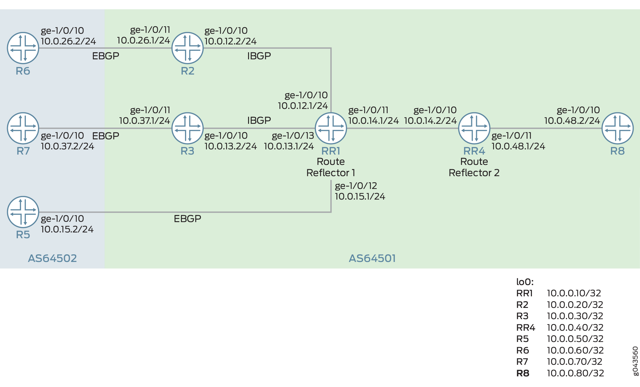 のためのBGP複数パスの選択的広告の設定
設定
CLIクイックコンフィグレーション
この例を迅速に設定するには、以下のコマンドをコピーしてテキストファイルに貼り付け、改行を削除し、ネットワーク設定に一致させる必要がある詳細情報を変更し、コマンドを [edit] 階層レベルでCLIにコピーアンドペーストして、設定モードからコミットを入力します。
ルーター RR1
set interfaces ge-1/0/10 unit 0 description RR1->R2
set interfaces ge-1/0/10 unit 0 family inet address 10.0.12.1/24
set interfaces ge-1/0/11 unit 0 description RR1->RR4
set interfaces ge-1/0/11 unit 0 family inet address 10.0.14.1/24
set interfaces ge-1/0/12 unit 0 description RR1->R5
set interfaces ge-1/0/12 unit 0 family inet address 10.0.15.1/24
set interfaces ge-1/0/13 unit 0 description RR1->R3
set interfaces ge-1/0/13 unit 0 family inet address 10.0.13.1/24
set interfaces lo0 unit 0 family inet address 10.0.0.10/32
set protocols bgp group rr type internal
set protocols bgp group rr local-address 10.0.0.10
set protocols bgp group rr cluster 10.0.0.10
set protocols bgp group rr multipath
set protocols bgp group rr neighbor 10.0.0.20
set protocols bgp group rr neighbor 10.0.0.30
set protocols bgp group e1 type external
set protocols bgp group e1 neighbor 10.0.15.2 local-address 10.0.15.1
set protocols bgp group e1 neighbor 10.0.15.2 peer-as 64502
set protocols bgp group rr_rr type internal
set protocols bgp group rr_rr local-address 10.0.0.10
set protocols bgp group rr_rr neighbor 10.0.0.40 family inet unicast add-path send path-count 6
set protocols bgp group rr_rr neighbor 10.0.0.40 family inet unicast add-path send multipath
set protocols ospf area 0.0.0.0 interface lo0.10 passive
set protocols ospf area 0.0.0.0 interface ge-1/0/10
set protocols ospf area 0.0.0.0 interface ge-1/0/13
set protocols ospf area 0.0.0.0 interface ge-1/0/11
set protocols ospf area 0.0.0.0 interface ge-1/0/12
set policy-options prefix-list match_199 199.1.1.1/32
set policy-options policy-statement loadbal_199 term match_100 from prefix-list match_199
set policy-options policy-statement loadbal_199 from route-filter 199.1.1.1/32 exact
set policy-options policy-statement loadbal_199 then load-balance per-packet
set routing-options router-id 10.0.0.10
set routing-options autonomous-system 64501
set routing-options forwarding-table export loadbal_199
ルーターR2
set interfaces ge-1/0/10 unit 0 description R2->RR1
set interfaces ge-1/0/10 unit 0 family inet address 10.0.12.2/24
set interfaces ge-1/0/11 unit 0 description R2->R6
set interfaces ge-1/0/11 unit 0 family inet address 10.0.26.1/24
set interfaces lo0 unit 0 family inet address 10.0.0.20/32
set protocols bgp group rr local-address 10.0.0.20
set protocols bgp group rr neighbor 10.0.0.10 export set_nh_self
set protocols bgp group e1 type external
set protocols bgp group e1 neighbor 10.0.26.2 peer-as 64502
set protocols ospf area 0.0.0.0 interface lo0.20 passive
set protocols ospf area 0.0.0.0 interface ge-1/0/10
set protocols ospf area 0.0.0.0 interface ge-1/0/11
set policy-options policy-statement set_nh_self then next-hop self
set routing-options autonomous-system 64501
ルーターR3
set interfaces ge-1/0/10 unit 0 description R3->RR1
set interfaces ge-1/0/10 unit 0 family inet address 10.0.13.2/24
set interfaces ge-1/0/11 unit 0 description R3->R7
set interfaces ge-1/0/11 unit 0 family inet address 10.0.37.1/24
set interfaces lo0 unit 0 family inet address 10.0.0.30/32
set protocols bgp group rr type internal
set protocols bgp group rr local-address 10.0.0.30
set protocols bgp group rr neighbor 10.0.0.10 export set_nh_self
set protocols bgp group e1 type external
set protocols bgp group e1 neighbor 10.0.37.2 peer-as 64502
set protocols ospf area 0.0.0.0 interface lo0.30 passive
set protocols ospf area 0.0.0.0 interface ge-1/0/10
set protocols ospf area 0.0.0.0 interface ge-1/0/13
set policy-options policy-statement set_nh_self then next-hop self
set routing-options autonomous-system 64501
ルーター RR4
set interfaces ge-1/0/10 unit 0 description RR4->RR1
set interfaces ge-1/0/10 unit 0 family inet address 10.0.14.2/24
set interfaces ge-1/0/11 unit 0 description RR4->R8
set interfaces ge-1/0/11 unit 0 family inet address 10.0.48.1/24
set interfaces lo0 unit 0 family inet address 10.0.0.40/32
set protocols bgp group rr type internal
set protocols bgp group rr local-address 10.0.0.40
set protocols bgp group rr family inet unicast add-path receive
set protocols bgp group rr neighbor 10.0.0.10
set protocols bgp group rr_client type internal
set protocols bgp group rr_client local-address 10.0.0.40
set protocols bgp group rr_client cluster 10.0.0.40
set protocols bgp group rr_client neighbor 10.0.0.80 family inet unicast add-path send prefix-policy addpath-communities-send-4713-100
set protocols bgp group rr_client neighbor 10.0.0.80 family inet unicast add-path send path-count 2
set protocols bgp group rr_client neighbor 10.0.0.80 family inet unicast add-path send multipath
set protocols ospf area 0.0.0.0 interface ge-1/0/10
set protocols ospf area 0.0.0.0 interface lo0.40 passive
set protocols ospf area 0.0.0.0 interface ge-1/0/11
set policy-options prefix-list match_199 199.1.1.1/32
set routing-options autonomous-system 64501
ルーターR5
set interfaces ge-1/0/10 unit 0 description R5->RR1
set interfaces ge-1/0/10 unit 0 family inet address 10.0.15.2/24
set interfaces lo0 unit 0 family inet address 10.0.0.50/32
set protocols bgp group e1 type external
set protocols bgp group e1 neighbor 10.0.15.1 export s2b
set protocols bgp group e1 neighbor 10.0.15.1 peer-as 64501
set policy-options policy-statement s2b from protocol static
set policy-options policy-statement s2b from protocol direct
set policy-options policy-statement s2b then community add addpath-community
set policy-options policy-statement s2b then as-path-expand 2
set policy-options policy-statement s2b then accept
set policy-options community addpath-community members 4713:100
set routing-options static route 199.1.1.1/32 reject
set routing-options static route 198.1.1.1/32 reject
set routing-options autonomous-system 64502
ルーターR6
set interfaces ge-1/0/10 unit 0 description R6->R2
set interfaces ge-1/0/10 unit 0 family inet address 10.0.26.2/24
set interfaces lo0 unit 0 family inet address 10.0.0.60/32
set protocols bgp group e1 type external
set protocols bgp group e1 neighbor 10.0.26.1 export s2b
set protocols bgp group e1 neighbor 10.0.26.1 peer-as 64501
set policy-options policy-statement s2b from protocol static
set policy-options policy-statement s2b from protocol direct
set policy-options policy-statement s2b then community add addpath-community
set policy-options policy-statement s2b then accept
set policy-options community addpath-community members 4713:100
set routing-options static route 199.1.1.1/32 reject
set routing-options static route 198.1.1.1/32 reject
set routing-options autonomous-system 64502
ルーターR7
set interfaces ge-1/0/10 unit 0 description R7->R3
set interfaces ge-1/0/10 unit 0 family inet address 10.0.37.2/24
set interfaces lo0 unit 0 family inet address 10.0.0.70/32
set protocols bgp group e1 type external
set protocols bgp group e1 neighbor 10.0.37.1 export s2b
set protocols bgp group e1 neighbor 10.0.37.1 peer-as 64501
set policy-options policy-statement s2b from protocol static
set policy-options policy-statement s2b from protocol direct
set policy-options policy-statement s2b then community add addpath-community
set policy-options policy-statement s2b then accept
set policy-options community addpath-community members 4713:100
set routing-options static route 199.1.1.1/32 reject
set routing-options autonomous-system 64502
ルーターR8
set interfaces ge-1/0/10 unit 0 description R8->RR4
set interfaces ge-1/0/10 unit 0 family inet address 10.0.48.2/24
set interfaces lo0 unit 0 family inet address 10.0.0.80/32
set protocols bgp group rr type internal
set protocols bgp group rr local-address 10.0.0.80
set protocols bgp group rr neighbor 10.0.0.40 family inet unicast add-path receive
set protocols ospf area 0.0.0.0 interface lo0.0 passive
set protocols ospf area 0.0.0.0 interface ge-1/0/10.8
set routing-options autonomous-system 64501
set chassis fpc 1 pic 0 tunnel-services bandwidth 1g
ルーターRR1の設定
ステップバイステップの手順
次の例では、設定階層内のさまざまなレベルに移動する必要があります。CLIのナビゲーションについては、『CLIユーザーガイド』の「設定モードでのCLIエディターの使用」を参照してください。
ルーターRR1を設定するには:
適切なインターフェイス名、アドレス、およびその他のパラメーターを変更した後、他のルーターに対してこの手順を繰り返します。
-
インターフェイスにIPv4アドレスを設定します。
[edit interfaces]
user@RR1# set ge-1/0/10 unit 0 description RR1->R2
user@RR1# set ge-1/0/10 unit 0 family inet address 10.0.12.1/24
user@RR1# set ge-1/0/11 unit 0 description RR1->RR4
user@RR1# set ge-1/0/11 unit 0 family inet address 10.0.14.1/24
user@RR1# set ge-1/0/12 unit 0 description RR1->R5
user@RR1# set ge-1/0/12 unit 0 family inet address 10.0.15.1/24
user@RR1# set ge-1/0/13 unit 0 description RR1->R3
user@RR1# set ge-1/0/13 unit 0 family inet address 10.0.13.1/24
-
ループバックアドレスを設定します。
[edit interfaces]
user@RR1# set lo0 unit 0 family inet address 10.0.0.10/32
-
OSPFやIS-ISなどの内部ゲートウェイプロトコル(IGP)を設定します。
[edit protocols]
user@RR1# set ospf area 0.0.0.0 interface lo0.10 passive
user@RR1# set ospf area 0.0.0.0 interface ge-1/0/10
user@RR1# set ospf area 0.0.0.0 interface ge-1/0/13
user@RR1# set ospf area 0.0.0.0 interface ge-1/0/11
user@RR1# set ospf area 0.0.0.0 interface ge-1/0/12
-
内部ルーター R2 および R3 に接続するインターフェイスに対して、内部グループ rr を設定します。
[edit protocols] user@RR1# set bgp group rr type internal user@RR1# set bgp group rr local-address 10.0.0.10 user@RR1# set bgp group rr cluster 10.0.0.10 user@RR1# set bgp group rr neighbor 10.0.0.20 user@RR1# set bgp group rr neighbor 10.0.0.30
-
内部BGPグループrrのロードバランシングを設定します。
[edit protocols] user@RR1# set bgp group rr multipath
-
ルートリフレクタの内部グループrr_rrを設定します。
[edit protocols] user@RR1# set bgp group rr_rr type internal user@RR1# set bgp group rr_rr local-address 10.0.0.10
-
addpath マルチパス機能を設定して、貢献者の複数パスのみを広告し、広告されるマルチパスの数を 6 に制限します。
[edit protocols] user@RR1# set bgp group rr_rr neighbor 10.0.0.40 family inet unicast add-path send multipath user@RR1# set bgp group rr_rr neighbor 10.0.0.40 family inet unicast add-path send path-count 6
-
外部エッジルーターに接続するインターフェイスでEBGPを設定します。
[edit protocols] user@RR1# set bgp group e1 type external user@RR1# set bgp group e1 neighbor 10.0.15.2 local-address 10.0.15.1 user@RR1# set bgp group e1 neighbor 10.0.15.2 peer-as 64502
-
パケットロードバランシングごとのポリシー loadbal_199を定義します。
[edit policy-options] user@RR1# set prefix-list match_199 199.1.1.1/32 user@RR1# set policy-statement loadbal_199 term match_100 from prefix-list match_199 user@RR1# set policy-statement loadbal_199 from route-filter 199.1.1.1/32 exact user@RR1# set policy-statement loadbal_199 then load-balance per-packet
-
定義したエクスポートポリシー loadbal_199を適用します。
[edit routing-options] user@RR1# set forwarding-table export loadbal_199
-
BGPホストのルーターIDと自律システムを設定します。
[edit routing-options] user@RR1# set router-id 10.0.0.10 user@RR1# set autonomous-system 64501
結果
設定モードから、 show interfaces、 show protocols、 show routing-options、および show policy-options コマンドを入力して設定を確認します。出力に意図した設定が表示されない場合は、この例の手順を繰り返して設定を修正します。
[edit]
user@RR1# show interfaces
ge-1/0/10 {
unit 0 {
description RR1->R2;
family inet {
address 10.0.12.1/24;
}
}
}
ge-1/0/11 {
unit 0 {
description RR1->RR4;
family inet {
address 10.0.14.1/24;
}
}
}
ge-1/0/12 {
unit 0 {
description RR1->R5;
family inet {
address 10.0.15.1/24;
}
}
}
ge-1/0/13 {
unit 0 {
description RR1->R3;
family inet {
address 10.0.13.1/24;
}
}
}
lo0 {
unit 0 {
family inet {
address 10.0.0.10/32;
}
}
}
[edit]
user@RR1# show protocols
bgp {
group rr {
type internal;
local-address 10.0.0.10;
cluster 10.0.0.10;
multipath;
neighbor 10.0.0.20;
neighbor 10.0.0.30;
}
group e1 {
type external;
neighbor 10.0.15.2 {
local-address 10.0.15.1;
peer-as 64502;
}
}
group rr_rr {
type internal;
local-address 10.0.0.10;
neighbor 10.0.0.40 {
family inet {
unicast {
add-path {
send {
path-count 6;
multipath;
}
}
}
}
}
}
}
ospf {
area 0.0.0.0 {
interface all;
interface fxp0.0 {
disable;
}
interface lo0.10 {
passive;
}
interface ge-1/0/10;
interface ge-1/0/13;
interface ge-1/0/11;
interface ge-1/0/12;
}
}
[edit]
user@RR1# show routing-options
router-id 10.0.0.10;
autonomous-system 64501;
forwarding-table {
export load-bal_199;
}
[edit]
user@RR1# show policy-options
prefix-list match_199 {
199.1.1.1/32;
}
policy-statement loadbal_199 {
term match_100 {
from {
prefix-list match_199;
}
}
from {
route-filter 199.1.1.1/32 exact;
}
then {
load-balance per-packet;
}
}
デバイスの設定が完了したら、設定をコミットします。
user@RR1# commit
検証
設定が正常に機能していることを確認します。
- スタティック ルート 199.1.1.1/32 のマルチパス ルートの検証
- マルチパス ルートがルーター RR1 からルーター RR4 にアドバタイズされていることの確認
- ルーター RR4 がルーター R8 に 199.1.1.1/32 用の 1 つのルートを広告していることの確認
スタティック ルート 199.1.1.1/32 のマルチパス ルートの検証
目的
宛先 199.1.1.1/32 で利用可能なマルチパス ルートを確認します。
アクション
運用モードから、ルーター RR1 で show route 199.1.1.1/32 detail コマンドを実行します。
user@RR1> show route 199.1.1.1/32 detail
inet.0: 22 destinations, 26 routes (22 active, 0 holddown, 0 hidden)
199.1.1.1/32 (3 entries, 2 announced)
*BGP Preference: 170/-101
Next hop type: Indirect, Next hop index: 0
Address: 0xae5cc90
Next-hop reference count: 1
Source: 10.0.0.20
Next hop type: Router, Next hop index: 1118
Next hop: 10.0.12.2 via lt-1/0/10.1, selected
Session Id: 0x0
Next hop type: Router, Next hop index: 1115
Next hop: 10.0.13.2 via lt-1/0/10.9
Session Id: 0x0
Protocol next hop: 10.0.0.20
Indirect next hop: 0xc409410 1048574 INH Session ID: 0x0
Protocol next hop: 10.0.0.30
Indirect next hop: 0xc409520 1048575 INH Session ID: 0x0
State: <Active Int Ext>
Local AS: 1 Peer AS: 1
Age: 4:03:29 Metric2: 1
Validation State: unverified
Task: BGP_1.10.0.0.20
Announcement bits (3): 2-KRT 3-BGP_RT_Background 4-Resolve tree 2
AS path: 2 I
Communities: 4713:100
Accepted Multipath
Localpref: 100
Router ID: 10.0.0.20
BGP Preference: 170/-101
Next hop type: Indirect, Next hop index: 0
Address: 0xae0ec10
Next-hop reference count: 4
Source: 10.0.0.30
Next hop type: Router, Next hop index: 1115
Next hop: 10.0.13.2 via lt-1/0/10.9, selected
Session Id: 0x0
Protocol next hop: 10.0.0.30
Indirect next hop: 0xc409520 1048575 INH Session ID: 0x0
State: <NotBest Int Ext>
Inactive reason: Not Best in its group - Router ID
Local AS: 64501 Peer AS: 64501
Age: 4:03:29 Metric2: 1
Validation State: unverified
Task: BGP_1.10.0.0.30
Announcement bits (1): 3-BGP_RT_Background
AS path: 2 I
Communities: 4713:100
Accepted MultipathContrib
Localpref: 100
Router ID: 10.0.0.30
BGP Preference: 170/-101
Next hop type: Router, Next hop index: 1105
Address: 0xae0e970
Next-hop reference count: 5
Source: 10.0.15.2
Next hop: 10.0.15.2 via lt-1/0/10.6, selected
Session Id: 0x0
State: <Ext>
Inactive reason: AS path
Local AS: 1 Peer AS: 2
Age: 4:05:01
Validation State: unverified
Task: BGP_2.10.0.15.2
AS path: 2 2 I
Communities: 4713:100
Accepted
Localpref: 100
Router ID: 10.0.0.50
意味
選択的広告マルチパス機能はルーター RR1 で有効になっており、ルート 199.1.1.1/32 で利用可能な複数のネクストホップがあります。ルート 199.1.1.1/32 で利用可能な 2 つのネクストホップは、10.0.0.20 と 10.0.0.30 です。
マルチパス ルートがルーター RR1 からルーター RR4 にアドバタイズされていることの確認
目的
ルーター RR1 がマルチパス ルートをアドバタイズしていることを確認します。
アクション
運用モードから、ルーター RR1 で show route advertising-protocol bgp 10.0.0.40 コマンドを実行します。
user@RR1> show route advertising-protocol bgp 10.0.0.40
inet.0: 22 destinations, 26 routes (22 active, 0 holddown, 0 hidden)
Prefix Nexthop MED Lclpref AS path
* 10.0.0.50/32 10.0.15.2 100 2 2 I
* 10.0.0.60/32 10.0.0.20 100 2 I
* 10.0.0.70/32 10.0.0.30 100 2 I
* 198.1.1.1/32 10.0.0.20 100 2 I
* 199.1.1.1/32 10.0.0.20 100 2 I
10.0.0.30 100 2 I
user@RR1> show route advertising-protocol bgp 10.0.0.40 detail
inet.0: 22 destinations, 26 routes (22 active, 0 holddown, 0 hidden)
* 10.0.0.50/32 (1 entry, 1 announced)
BGP group rr_rr type Internal
Nexthop: 10.0.15.2
Localpref: 100
AS path: [1] 2 2 I
Communities: 4713:100
Addpath Path ID: 1
….* 199.1.1.1/32 (3 entries, 2 announced)
BGP group rr_rr type Internal
Nexthop: 10.0.0.20
Localpref: 100
AS path: [1] 2 I
Communities: 4713:100
Cluster ID: 10.0.0.10
Originator ID: 10.0.0.20
Addpath Path ID: 1
BGP group rr_rr type Internal
Nexthop: 10.0.0.30
Localpref: 100
AS path: [1] 2 I
Communities: 4713:100
Cluster ID: 10.0.0.10
Originator ID: 10.0.0.30
Addpath Path ID: 2
意味
ルーター RR1 は、ルート 199.1.1.1/32 に対して 2 つのネクスト ホップ 10.0.0.20 および 10.0.0.30 をルーター RR4 にアドバタイズしています。
ルーター RR4 がルーター R8 に 199.1.1.1/32 用の 1 つのルートを広告していることの確認
目的
マルチパスはルーター RR4 で設定されていないため、ルート 199.1.1.1/32 は add-path の対象ではありません。ルーター RR4 がルーター R8 に対して 199.1.1.1/32 用の 1 つのルートのみを広告していることを確認します。
アクション
運用モードから、ルーター RR4 で show route advertising-protocol bgp 10.0.0.80 コマンドを実行します。
user@RR4> show route advertising-protocol bgp 10.0.0.80 detail
inet.0: 20 destinations, 21 routes (20 active, 0 holddown, 0 hidden)
* 10.0.0.50/32 (1 entry, 1 announced)
BGP group rr_client type Internal
Nexthop: 10.0.15.2
Localpref: 100
AS path: [1] 2 2 I
Communities: 4713:100
Cluster ID: 10.0.0.40
Originator ID: 10.0.0.10
Addpath Path ID: 1
…
* 198.1.1.1/32 (1 entry, 1 announced)
BGP group rr_client type Internal
Nexthop: 10.0.0.20
Localpref: 100
AS path: [1] 2 I (Originator)
Cluster list: 10.0.0.10
Originator ID: 10.0.0.20
Communities: 4713:100
Cluster ID: 10.0.0.40
Addpath Path ID: 1
* 199.1.1.1/32 (2 entries, 1 announced)
BGP group rr_client type Internal
Nexthop: 10.0.0.20
Localpref: 100
AS path: [1] 2 I (Originator)
Cluster list: 10.0.0.10
Originator ID: 10.0.0.20
Communities: 4713:100
Cluster ID: 10.0.0.40
Addpath Path ID: 1
意味
ルーター RR4 でマルチパスが有効化されていないため、ルーター R8 には 1 つのパス 10.0.0.20 のみがアドバタイズされます。
例:BGPコミュニティ値に基づいてマルチパスを選択およびアドバタイズするためのルーティングポリシーの設定
利用可能な複数のパスをすべてアドバタイズすると、デバイス メモリの処理に大規模なオーバーヘッドが発生する可能性があります。事前にプレフィックスを実際に知らずに、プレフィックスの限定されたサブセットをアドバタイズする場合は、BGPコミュニティ値を使用して、BGPネイバーにアドバタイズする必要があるプレフィックスルートを識別できます。この例では、既知のBGPコミュニティ値に基づいて複数のパスをフィルタリングおよびアドバタイズするルーティングポリシーを定義する方法を示します。
要件
この例を設定する前に、デバイスの初期化以外の特別な設定を行う必要はありません。
この例では、以下のハードウェアおよびソフトウェアコンポーネントを使用しています。
-
M Series、MXシリーズ、またはT Seriesルーターの組み合わせが可能な8台のルーター
-
デバイス上の Junos OS リリース 16.1R2 以降
概要
Junos OS 16.1R2以降、コミュニティ値に基づいて、対象となる複数のパスプレフィックスを特定するポリシーを定義できます。BGPは、特定の宛先へのアクティブなパスに加えて、これらのコミュニティタグ付きルートをアドバタイズします。ルートのコミュニティ値がポリシーで定義されたコミュニティ値と一致しない場合、BGPはそのルートをアドバタイズしません。この機能により、BGPは特定の宛先に20個以下のパスをアドバタイズできます。事前にプレフィックスを実際に知らなくても、BGPが複数のパスに対して考慮するプレフィックス数を制限および設定できます。代わりに、既知のBGPコミュニティ値によって、プレフィックスがアドバタイズされるかどうかが判断されます。
トポロジー
図8では、RR1とRR4がルートリフレクタです。ルーター R2 および R3 は、ルート リフレクタ RR1 に対するクライアントです。ルーター R8 は、リフレクタ RR4 をルーティングするクライアントです。ルーターR5、R6、およびルーターR7は、スタティックルートをBGPに再分散します。ルーターR5は、スタティックルート199.1.1.1/32および198.1.1.1/32をコミュニティ値4713:100でアドバタイズします。
ルーターRR1は、ルーターRR4に最大6つのパス(宛先ごと)を送信するように設定されています。ルーターRR4は、ルーターR8に最大6つのパスを送信するように設定されています。ルーターR8は、ルーターRR4から複数のパスを受信するように設定されています。add-pathコミュニティ設定は、ルーターRR4が4713:100コミュニティ値のみを含むルートに対して複数のパスを送信することを制限します。ルーターRR4は、4714:100のコミュニティ値のみを含むマルチパスをフィルタリングしてアドバタイズします。
設定
CLIクイックコンフィグレーション
この例を迅速に設定するには、以下のコマンドをコピーしてテキストファイルに貼り付け、改行を削除し、ネットワーク設定に一致させる必要がある詳細情報を変更し、コマンドを [edit] 階層レベルでCLIにコピーアンドペーストして、設定モードからコミットを入力します。
ルーター RR1
set interfaces ge-1/0/10 unit 0 description RR1->R2 set interfaces ge-1/0/10 unit 0 family inet address 10.0.12.1/24 set interfaces ge-1/0/11 unit 0 description RR1->RR4 set interfaces ge-1/0/11 unit 0 family inet address 10.0.14.1/24 set interfaces ge-1/0/12 unit 0 description RR1->R5 set interfaces ge-1/0/12 unit 0 family inet address 10.0.15.1/24 set interfaces ge-1/0/13 unit 0 description RR1->R3 set interfaces ge-1/0/13 unit 0 family inet address 10.0.13.1/24 set interfaces lo0 unit 0 family inet address 10.0.0.10/32 set protocols bgp group rr type internal set protocols bgp group rr local-address 10.0.0.10 set protocols bgp group rr cluster 10.0.0.10 set protocols bgp group rr multipath set protocols bgp group rr neighbor 10.0.0.20 set protocols bgp group rr neighbor 10.0.0.30 set protocols bgp group e1 type external set protocols bgp group e1 neighbor 10.0.15.2 local-address 10.0.15.1 set protocols bgp group e1 neighbor 10.0.15.2 peer-as 64502 set protocols bgp group rr_rr type internal set protocols bgp group rr_rr local-address 10.0.0.10 set protocols bgp group rr_rr neighbor 10.0.0.40 family inet unicast add-path send path-count 6 set protocols ospf area 0.0.0.0 interface lo0.10 passive set protocols ospf area 0.0.0.0 interface ge-1/0/10 set protocols ospf area 0.0.0.0 interface ge-1/0/13 set protocols ospf area 0.0.0.0 interface ge-1/0/11 set protocols ospf area 0.0.0.0 interface ge-1/0/12 set routing-options router-id 10.0.0.10 set routing-options autonomous-system 64501
ルーターR2
set interfaces ge-1/0/10 unit 0 description R2->RR1 set interfaces ge-1/0/10 unit 0 family inet address 10.0.12.2/24 set interfaces ge-1/0/11 unit 0 description R2->R6 set interfaces ge-1/0/11 unit 0 family inet address 10.0.26.1/24 set interfaces lo0 unit 0 family inet address 10.0.0.20/32 set protocols bgp group rr local-address 10.0.0.20 set protocols bgp group rr neighbor 10.0.0.10 export set_nh_self set protocols bgp group e1 type external set protocols bgp group e1 neighbor 10.0.26.2 peer-as 64502 set protocols ospf area 0.0.0.0 interface lo0.20 passive set protocols ospf area 0.0.0.0 interface ge-1/0/10 set protocols ospf area 0.0.0.0 interface ge-1/0/11 set policy-options policy-statement set_nh_self then next-hop self set routing-options autonomous-system 64501
ルーターR3
set interfaces ge-1/0/10 unit 0 description R3->RR1 set interfaces ge-1/0/10 unit 0 family inet address 10.0.13.2/24 set interfaces ge-1/0/11 unit 0 description R3->R7 set interfaces ge-1/0/11 unit 0 family inet address 10.0.37.1/24 set interfaces lo0 unit 0 family inet address 10.0.0.30/32 set protocols bgp group rr type internal set protocols bgp group rr local-address 10.0.0.30 set protocols bgp group rr neighbor 10.0.0.10 export set_nh_self set protocols bgp group e1 type external set protocols bgp group e1 neighbor 10.0.37.2 peer-as 64502 set protocols ospf area 0.0.0.0 interface lo0.30 passive set protocols ospf area 0.0.0.0 interface ge-1/0/10 set protocols ospf area 0.0.0.0 interface ge-1/0/13 set policy-options policy-statement set_nh_self then next-hop self set routing-options autonomous-system 64501
ルーター RR4
set interfaces ge-1/0/10 unit 0 description RR4->RR1 set interfaces ge-1/0/10 unit 0 family inet address 10.0.14.2/24 set interfaces ge-1/0/11 unit 0 description RR4->R8 set interfaces ge-1/0/11 unit 0 family inet address 10.0.48.1/24 set interfaces lo0 unit 0 family inet address 10.0.0.40/32 set protocols bgp group rr type internal set protocols bgp group rr local-address 10.0.0.40 set protocols bgp group rr family inet unicast add-path receive set protocols bgp group rr neighbor 10.0.0.10 set protocols bgp group rr_client type internal set protocols bgp group rr_client local-address 10.0.0.40 set protocols bgp group rr_client cluster 10.0.0.40 set protocols bgp group rr_client neighbor 10.0.0.80 family inet unicast add-path send prefix-policy addpath-communities-send-4713-100 set protocols bgp group rr_client neighbor 10.0.0.80 family inet unicast add-path send path-count 6 set protocols ospf area 0.0.0.0 interface ge-1/0/10 set protocols ospf area 0.0.0.0 interface lo0.40 passive set protocols ospf area 0.0.0.0 interface ge-1/0/11 set policy-options community addpath-communities-send members 4713:100 set policy-options policy-statement addpath-communities-send-4713-100 term term1 from protocol bgp set policy-options policy-statement addpath-communities-send-4713-100 term term1 from community addpath-communities-send set policy-options policy-statement addpath-communities-send-4713-100 term term1 then add-path send-count 16 set policy-options policy-statement addpath-communities-send-4713-100 term term1 then accept set routing-options autonomous-system 64501
ルーターR5
set interfaces ge-1/0/10 unit 0 description R5->RR1 set interfaces ge-1/0/10 unit 0 family inet address 10.0.15.2/24 set interfaces lo0 unit 0 family inet address 10.0.0.50/32 set protocols bgp group e1 type external set protocols bgp group e1 neighbor 10.0.15.1 export s2b set protocols bgp group e1 neighbor 10.0.15.1 peer-as 64501 set policy-options policy-statement s2b from protocol static set policy-options policy-statement s2b from protocol direct set policy-options policy-statement s2b then community add addpath-community set policy-options policy-statement s2b then as-path-expand 2 set policy-options policy-statement s2b then accept set policy-options community addpath-community members 4713:100 set routing-options static route 199.1.1.1/32 reject set routing-options static route 198.1.1.1/32 reject set routing-options autonomous-system 64502
ルーターR6
set interfaces ge-1/0/10 unit 0 description R6->R2 set interfaces ge-1/0/10 unit 0 family inet address 10.0.26.2/24 set interfaces lo0 unit 0 family inet address 10.0.0.60/32 set protocols bgp group e1 type external set protocols bgp group e1 neighbor 10.0.26.1 export s2b set protocols bgp group e1 neighbor 10.0.26.1 peer-as 64501 set policy-options policy-statement s2b from protocol static set policy-options policy-statement s2b from protocol direct set policy-options policy-statement s2b then community add addpath-community set policy-options policy-statement s2b then accept set policy-options community addpath-community members 4713:100 set routing-options static route 199.1.1.1/32 reject set routing-options static route 198.1.1.1/32 reject set routing-options autonomous-system 64502
ルーターR7
set interfaces ge-1/0/10 unit 0 description R7->R3 set interfaces ge-1/0/10 unit 0 family inet address 10.0.37.2/24 set interfaces lo0 unit 0 family inet address 10.0.0.70/32 set protocols bgp group e1 type external set protocols bgp group e1 neighbor 10.0.37.1 export s2b set protocols bgp group e1 neighbor 10.0.37.1 peer-as 64501 set policy-options policy-statement s2b from protocol static set policy-options policy-statement s2b from protocol direct set policy-options policy-statement s2b then community add addpath-community set policy-options policy-statement s2b then accept set policy-options community addpath-community members 4713:100 set routing-options static route 199.1.1.1/32 reject set routing-options autonomous-system 64502
ルーターR8
set interfaces ge-1/0/10 unit 0 description R8->RR4 set interfaces ge-1/0/10 unit 0 family inet address 10.0.48.2/24 set interfaces lo0 unit 0 family inet address 10.0.0.80/32 set protocols bgp group rr type internal set protocols bgp group rr local-address 10.0.0.80 set protocols bgp group rr neighbor 10.0.0.40 family inet unicast add-path receive set protocols ospf area 0.0.0.0 interface lo0.0 passive set protocols ospf area 0.0.0.0 interface ge-1/0/10.8 set routing-options autonomous-system 64501 set chassis fpc 1 pic 0 tunnel-services bandwidth 1g
ルーターRR4の設定
ステップバイステップの手順
次の例では、設定階層内のさまざまなレベルに移動する必要があります。CLIのナビゲーションについては、『CLIユーザーガイド』の「設定モードでのCLIエディターの使用」を参照してください。
ルーターRR4を設定するには:
適切なインターフェイス名、アドレス、およびその他のパラメーターを変更した後、他のルーターに対してこの手順を繰り返します。
-
インターフェイスにIPv4アドレスを設定します。
[edit interfaces] user@RR4# set ge-1/0/10 unit 0 description RR4->RR1 user@RR4# set ge-1/0/10 unit 0 family inet address 10.0.14.2/24 user@RR4# set ge-1/0/11 unit 0 description RR4->R8 user@RR4# set ge-1/0/11 unit 0 family inet address 10.0.48.1/24
-
ループバックアドレスを設定します。
[edit interfaces] user@RR4# set lo0 unit 0 family inet address 10.0.0.40/32
-
OSPFまたはその他の内部ゲートウェイプロトコル(IGP)を設定します。
[edit protocols] user@RR4# set ospf area 0.0.0.0 interface lo0.40 passive user@RR4# set ospf area 0.0.0.0 interface ge-1/0/10 user@RR4# set ospf area 0.0.0.0 interface ge-1/0/11
-
ルートリフレクタのクライアントには、ルートリフレクタとrr_clientの2つのIBGPグループrrを設定します。
[edit protocols] user@RR4# set bgp group rr type internal user@RR4# set bgp group rr local-address 10.0.0.40 user@RR4# set bgp group rr family inet unicast add-path receive user@RR4# set bgp group rr neighbor 10.0.0.10 user@RR4# set bgp group rr_client type internal user@RR4# set bgp group rr_client local-address 10.0.0.40 user@RR4# set bgp group rr_client cluster 10.0.0.40
-
この機能を設定し、4713:100のコミュニティ値のみを含む複数のパスを送信し、アドバタイズされるマルチパスの数を6に制限します。
[edit protocols] user@RR4# set bgp group rr_client neighbor 10.0.0.80 family inet unicast add-path send prefix-policy addpath-communities-send-4713-100 user@RR4# set bgp group rr_client neighbor 10.0.0.80 family inet unicast add-path send path-count 6
-
コミュニティ値4713:100でプレフィックスをフィルタリングするポリシー
addpath-community-members 4713:100を定義し、デバイスがルーターR8に最大16個のパスを送信するように制限します。この制限は、BGPグループ階層レベルで以前に設定されたadd-path send path-count6を上書きします。[edit policy-options] user@RR4# set community addpath-communities-send members 4713:100 user@RR4# set policy-statement addpath-communities-send-4713-100 term term1 from protocol bgp user@RR4# set policy-statement addpath-communities-send-4713-100 term term1 from community addpath-communities-send user@RR4# set policy-statement addpath-communities-send-4713-100 term term1 then add-path send-count 16 user@RR4# set policy-statement addpath-communities-send-4713-100 term term1 then accept
-
BGPホストのルーターIDと自律システムを設定します。
[edit routing-options] user@RR4# set router-id 10.0.0.40 user@RR4# set autonomous-system 64501
結果
設定モードから、 show interfaces、 show protocols、 show routing-options、および show policy-options コマンドを入力して設定を確認します。出力に意図した設定が表示されない場合は、この例の手順を繰り返して設定を修正します。
[edit]
user@RR4# show interfaces
ge-1/0/10 {
unit 0 {
description RR4->RR1;
family inet {
address 10.0.14.2/24;
}
}
}
ge-1/0/11 {
unit 0 {
description RR4->R8;
family inet {
address 10.0.48.1/24;
}
}
}
lo0 {
unit 0 {
family inet {
address 10.0.0.10/32;
}
}
}
[edit]
user@RR4# show protocols
bgp {
group rr {
type internal;
local-address 10.0.0.40;
family inet {
unicast {
add-path {
receive;
}
}
}
neighbor 10.0.0.10;
}
group rr_client {
type internal;
local-address 10.0.0.40;
cluster 10.0.0.40;
neighbor 10.0.0.80 {
family inet {
unicast {
add-path {
send {
prefix-policy addpath-communities-send-4713-100;
path-count 6;
}
}
}
}
}
}
}
ospf {
area 0.0.0.0 {
interface ge-1/0/10.0;
interface lo0.40 {
passive;
}
interface ge-1/0/11.0;
}
}
[edit]
user@RR4# show policy-options
policy-statement addpath-communities-send-4713-100 {
term term1 {
from {
protocol bgp;
community addpath-communities-send;
}
then {
add-path send-count 16;
accept;
}
}
}
community addpath-communities-send members 4713:100;
[edit] user@RR4# show routing-options router-id 10.0.0.40; autonomous-system 64501;
デバイスの設定が完了したら、設定をコミットします。
user@RR4# commit
検証
設定が正常に機能していることを確認します。
- マルチパス ルートがルーター RR4 からルーター R8 にアドバタイズされていることの検証
- ルーターR8がルーターRR4がアドバタイズするマルチパスルートを受信していることを検証
- ルーターRR4が、コミュニティ値4713:100のマルチパスルートのみをルーターR8にアドバタイズしていることを検証
マルチパス ルートがルーター RR4 からルーター R8 にアドバタイズされていることの検証
目的
ルーターRR4がルーターR8に複数のパスを送信できることを確認します。
アクション
運用モードから、ルーター RR4 で show route advertising-protocol bgp neighbor-address コマンドを実行します。
user@RR4> show route advertising-protocol bgp 10.0.0.80
inet.0: 20 destinations, 23 routes (20 active, 0 holddown, 0 hidden)
Prefix Nexthop MED Lclpref AS path
* 10.0.0.50/32 10.0.15.2 100 2 2 I
* 10.0.0.60/32 10.0.0.20 100 2 I
* 10.0.0.70/32 10.0.0.30 100 2 I
* 198.1.1.1/32 10.0.0.20 100 2 I
10.0.15.2 100 2 2 I
* 199.1.1.1/32 10.0.0.20 100 2 I
10.0.0.30 100 2 I
10.0.15.2 100 2 2 I
意味
ルーターRR4は、ルーターR8に複数のパス10.0.0.20、10.0.0.30、および10.0.15.2をアドバタイズしています。
ルーターR8がルーターRR4がアドバタイズするマルチパスルートを受信していることを検証
目的
ルーターR8がルーターRR4からマルチパスルートを受信していることを確認します。
アクション
運用モードから、ルーターR8で show route receive-protocol bgp neighbor-address コマンドを実行します。
user@R8> show route receive-protocol bgp 10.0.0.40
inet.0: 19 destinations, 22 routes (19 active, 0 holddown, 0 hidden)
Prefix Nexthop MED Lclpref AS path
* 10.0.0.50/32 10.0.15.2 100 2 2 I
* 10.0.0.60/32 10.0.0.20 100 2 I
* 10.0.0.70/32 10.0.0.30 100 2 I
* 198.1.1.1/32 10.0.0.20 100 2 I
10.0.15.2 100 2 2 I
* 199.1.1.1/32 10.0.0.20 100 2 I
10.0.0.30 100 2 I
10.0.15.2 100 2 2 I
意味
ルーターR8は、ルーターRR4からルート199.1.1.1/32で、複数のネクストホップ10.0.0.20、10.0.0.30、および10.0.15.2を受信しています。
ルーターRR4が、コミュニティ値4713:100のマルチパスルートのみをルーターR8にアドバタイズしていることを検証
目的
ルーターRR4は、コミュニティ値4713:100のマルチパスルートを、ルーターR8にのみアドバタイズする必要があります。
アクション
運用モードから、ルーター RR4 で show route 199.1.1.1/32 detail コマンドを実行します。
user@RR4> show route 199.1.1.1/32 detail
inet.0: 20 destinations, 23 routes (20 active, 0 holddown, 0 hidden)
199.1.1.1/32 (3 entries, 3 announced)
*BGP Preference: 170/-101
Next hop type: Indirect, Next hop index: 0
Address: 0xae0ea90
Next-hop reference count: 6
Source: 10.0.0.10
Next hop type: Router, Next hop index: 1115
Next hop: 10.0.14.1 via ge-1/0/10.4, selected
Session Id: 0x0
Protocol next hop: 10.0.0.20
Indirect next hop: 0xc4091f0 1048581 INH Session ID: 0x0
State: <Active Int Ext>
Local AS: 1 Peer AS: 1
Age: 4d 20:56:53 Metric2: 2
Validation State: unverified
Task: BGP_1.10.0.0.10
Announcement bits (3): 2-KRT 3-BGP_RT_Background 4-Resolve tree 2
AS path: 2 I (Originator)
Cluster list: 10.0.0.10
Originator ID: 10.0.0.20
Communities: 4713:100
Accepted
Localpref: 100
Router ID: 10.0.0.10
Addpath Path ID: 1
BGP Preference: 170/-101
Next hop type: Indirect, Next hop index: 0
Address: 0xae0eb50
Next-hop reference count: 3
Source: 10.0.0.10
Next hop type: Router, Next hop index: 1115
Next hop: 10.0.14.1 via lt-1/0/10.4, selected
Session Id: 0x0
Protocol next hop: 10.0.0.30
Indirect next hop: 0xc409300 1048582 INH Session ID: 0x0
State: <NotBest Int Ext>
Inactive reason: Not Best in its group - Router ID
Local AS: 1 Peer AS: 1
Age: 4d 20:56:53 Metric2: 2
Validation State: unverified
Task: BGP_1.10.0.0.10
Announcement bits (1): 3-BGP_RT_Background
AS path: 2 I (Originator)
Cluster list: 10.0.0.10
Originator ID: 10.0.0.30
Communities: 4713:100
Accepted
Localpref: 100
Router ID: 10.0.0.10
Addpath Path ID: 2
BGP Preference: 170/-101
Next hop type: Indirect, Next hop index: 0
Address: 0xae0e9d0
Next-hop reference count: 4
Source: 10.0.0.10
Next hop type: Router, Next hop index: 1115
Next hop: 10.0.14.1 via lt-1/0/10.4, selected
Session Id: 0x0
Protocol next hop: 10.0.15.2
Indirect next hop: 0xc4090e0 1048580 INH Session ID: 0x0
State: <Int Ext>
Inactive reason: AS path
Local AS: 1 Peer AS: 1
Age: 4d 20:56:53 Metric2: 2
Validation State: unverified
Task: BGP_1.10.0.0.10
Announcement bits (1): 3-BGP_RT_Background
AS path: 2 2 I
Communities: 4713:100
Accepted
Localpref: 100
Router ID: 10.0.0.10
Addpath Path ID: 3
意味
ルーターRR4は、コミュニティ値4713:100の3つのパスをルーターR8にアドバタイズしています。
BGPマルチパス上での再帰的解決の設定
Junos OS リリース 17.3R1 以降、単一のプロトコル ネクストホップを持つ BGP プレフィックスが、複数の解決済みパス(ユニリスト)を持つ別の BGP プレフィックス上で解決される場合、すべてのパスがプロトコル ネクストホップ解決に選択されます。以前の Junos OS リリースでは、リゾルバが IBGP マルチパス ルートのすべてのパスにわたる負荷分散をサポートしていなかったため、プロトコルのネクストホップ解決には 1 つのパスのみが選択されます。ルーティングプロトコルプロセス(rpd)内のリゾルバは、プロトコルネクストホップアドレス(PNH)を即時転送ネクストホップに解決します。BGP再帰的解決機能は、IBGPマルチパスルート上のルートを解決し、すべての実現可能なパスをネクストホップとして使用するためにリゾルバーを強化します。この機能は、高等コストのマルチパスとシームレスなMPLSトポロジーを持つWANネットワークなど、インフラストラクチャ接続の確立にBGPが使用される高密度接続ネットワークに有効です。
BGPマルチパスの再帰的解決の設定を開始する前に、以下を実行する必要があります。
デバイスインターフェイスを設定します。
OSPFまたはその他のIGPプロトコルを設定します。
MPLSとLDPを設定します。
BGPを設定します。
マルチパスでの再帰的解決を設定するには、
関連項目
負荷分散のためのRSVPおよびLDP LSPのECMPネクストホップの設定
Junos OSは、RSVPおよびLDP LSPに対して、16、32、64、または128の等価コストマルチパス(ECMP)ネクストホップの設定をサポートしています。大量のトラフィックが発生するネットワークでは、最大128個のLSPでトラフィックの負荷分散を行うことができる柔軟性を備えています。
ECMPネクストホップの最大制限を設定するには、[edit chassis]階層レベルでmaximum-ecmp next-hopsステートメントを含めます。
[edit chassis] maximum-ecmp next-hops;
このステートメントを使用すると、ECMPネクストホップの最大制限を16、32、64、または128に設定できます。デフォルトの上限は16です。
1枚以上のMPC(モジュラーポートコンセントレータ)カードを搭載し、Junos OS 11.4以前がインストールされているMXシリーズルーターは、16ネクストホップのみのmaximum-ecmpステートメントの設定をサポートしています。maximum-ecmp ステートメントに 32 または 64 のネクスト ホップを設定してはいけません。32または64ネクストホップで設定をコミットすると、以下の警告メッセージが表示されます。
Error: Number of members in Unilist NH exceeds the maximum supported 16 on Trio.
次のタイプのルートは、最大128台のECMPゲートウェイに対して、ECMP最大ネクストホップ設定をサポートしています。
-
ダイレクトおよびインダイレクトネクストホップECMPを持つ静的IPv4およびIPv6ルート
-
関連するIGPルートで学習したLDPのイングレスおよびトランジットIGPルート
-
LSPに対して作成されるRSVP ECMPネクストホップ
-
OSPF IPv4およびIPv6ルートECMP
-
IS-IS IPv4およびIPv6ルートECMP
-
EBGP IPv4およびIPv6ルートECMP
-
IBGP(IGPルート上の解決)IPv4およびIPv6ルートECMP
ECMPネクスト・ホップ128個までの拡張ECMP制限は、MPLSルート上で解決するレイヤー3 VPN、レイヤー2 VPN、レイヤー2回線、およびVPLSサービスにも適用されます。これは、MPLSルートで利用可能なECMPパスもそのトラフィックによって使用できるためです。
RSVP LSPに帯域幅割り当てが設定されている場合、LSPが16を超えるECMPネクストホップでは、設定された帯域幅に基づいてトラフィックが最適に分散されません。割り当て帯域が小さいLSPの中には、高い帯域で設定されたLSPよりも多くのトラフィックを受けるものがあります。トラフィックの配信が設定された帯域幅に厳密に適合していません。この注意事項は、以下のルーターに適用されます。
-
MPCを除くすべてのタイプのFPCおよびDPCを搭載したMXシリーズルーター。この注意事項は、Junos Trioチップセットをベースにしたラインカードを搭載したMXシリーズルーターには適用 されません 。
ECMPネクスト・ホップの詳細を表示するには、 show route コマンドを発行します。この show route summary command には、ECMP最大制限に関する現在の設定も表示されます。ECMP LDPパスの詳細を表示するには、 traceroute mpls ldp コマンドを発行します。
関連項目
ECMP グループの一貫したロード バランシングの設定
パケット単位のロードバランシングにより、トラフィックを複数の等コストパスに分散させることができます。デフォルトでは、1 つ以上のパスに障害が発生した場合、ハッシュ アルゴリズムがすべてのパスのネクストホップを再計算し、通常、すべてのフローを再分配します。 一貫したロードバランシング により、この動作をオーバーライドして、非アクティブなリンクに対するフローのみをリダイレクトすることができます。既存のアクティブなフローはすべて中断されることなく維持されます。データセンター環境では、リンクに障害が発生した場合にすべてのフローを再分配すると、トラフィックが大幅に減少したり、リンクがアクティブなサーバーのサービスが失われたりする可能性があります。一貫したロードバランシングは、すべてのアクティブなリンクを維持し、代わりに1つ以上のリンク障害の影響を受けるフローのみを再マップします。この機能により、アクティブな状態のリンクに接続されたフローは中断されることなく継続されます。
この機能は、ECMP(Equal Cost マルチパス)グループのメンバーがシングルホップの BGP セッションで外部 BGP ネイバーであるトポロジーに適用されます。新しいECMPパスを追加したり、既存のパスを変更したりした場合は、一貫したロードバランシングは適用されません。中断を最小限に抑えて新しいパスを追加するには、既存のパスを変更せずに新しい ECMP グループを定義します。このようにして、既存の接続を終了させることなく、クライアントを徐々に新しいグループに移動させることができます。
(MXシリーズの場合)MPC(モジュラーポートコンセントレータ)のみがサポートされます。
IPv4 と IPv6 の両方のパスがサポートされています。
仮想ルーティング転送(VRF)インスタンスまたは他のルーティング インスタンスの一部である ECMP グループもサポートされています。
マルチキャストトラフィックはサポートされていません。
アグリゲーション インターフェイスはサポートされていますが、リンク アグリゲーション(LAG)バンドルのメンバー間で一貫したロードバランシングはサポートされていません。LAGバンドルのアクティブメンバーからのトラフィックは、1つまたは複数のメンバーリンクに障害が発生した場合、別のアクティブメンバーに移動する場合があります。1 つ以上の LAG メンバー リンクに障害が発生した場合、フローはリハッシュされます。
ルーターまたはスイッチあたり最大 1,000 IP プレフィックスまで一貫したロードバランシングを適用することを強くお勧めします。
IRB(統合型ルーティングおよびブリッジング)インターフェイス上のレイヤー 3 アドジャシーをサポートします。
BGP add-path 機能を設定することで、ECMPグループ内の1つ以上のパスに障害が発生した場合に、障害パスを新しいアクティブパスに置き換えることができます。障害パスの置換を設定することで、障害パスのみのトラフィック フローがリダイレクトされるようになります。アクティブなパスのトラフィック フローは変更されません。
GRE(Generic Routing Encapsulation)トンネルインターフェイスで一貫したロードバランシングを設定する場合、GREトンネルインターフェイス上のレイヤー3隣接が転送テーブルに正しくインストールされるように、遠端トンネルインターフェイスのinetアドレスを指定する必要があります。ただし、GRE トンネル インターフェイスを介した ECMP 高速再ルート(FRR)は、一貫したロードバランシング中はサポートされません。
[edit interfaces interface name unit unit name family inet address address]階層レベルで一貫したロードバランシングで設定されたルーターで宛先アドレスを指定できます。次に例を示します。[edit interfaces] user@host# set interfaces gr-4/0/0 unit 21 family inet address 10.10.31.2/32 destination 10.10.31.1
汎用ルーティングカプセル化の詳細については、 汎用ルーティングカプセル化トンネルの設定を参照してください。
コンシステントロードバランシングは、EBGPネイバーのBGPマルチホップをサポートしません。したがって、コンシステントロードバランシングで設定されたデバイスでは、
multihopオプションを有効にしないでください。
ECMP グループに対して一貫したロードバランシングを設定するには:
複数のECMP BGPピアを使用したネットワーク耐障害性の向上
概要
等価コストマルチパス(ECMP)は、同じセッションまたはフローのトラフィックを等コストの複数のパスに伝送できるようにするネットワークルーティング戦略です。フローは、送信元と宛先が同じトラフィックです。ECMP プロセスは、フローの宛先に向かう正当なイコールコスト ネクスト ホップであるルーターを特定します。その後、デバイスはロードバランシングを使用して、これらの複数の等コストのネクストホップにトラフィックを均等に分散します。ECMP は、ネットワーク管理者が、同じ宛先へのリンクで未使用の帯域幅を最大限に活用することで、トラフィックの負荷分散と帯域幅の増加を可能にするメカニズムです。
BGPではECMPをよく使用します。各 BGP ルートは、複数の ECMP ネクスト ホップを持つことができます。BGPエクスポートポリシーは、これらのネクストホップにBGPルートをアドバタイズするかどうかを決定します。ネットワーク管理者は、これらの ECMP ピアとの間での BGP プレフィックスのアドバタイズと引き出しを制御できます。BGPエクスポートポリシーは、ポリシーがプレフィックスを受信するECMP BGPピアの数に基づいて、BGPプレフィックスをアドバタイズするかどうかを決定します。
最小数のECMP BGPピアからBGPルートプレフィックスを受信しない限り、BGPルートを取り消すようにBGPエクスポートポリシーを設定するBGPBGPできます。BGPルートに複数のECMP BGPピアを要求することで、リンク障害時の耐障害性が向上します。
利点
-
ネットワークの耐障害性を向上
-
リンクの偶発的な過負荷を防止
-
ロードバランシングを支援
設定
BGPエクスポートポリシーは、BGPルートのECMPネクストホップの数を、[edit policy-options policy-statement policy-name]または [edit policy-options policy-statement policy-name term term-name]のいずれかの階層でfrom nexthop-ecmpステートメントで設定した値と比較します。
このステートメントのオプションは次のとおりです。
-
value:条件を満たすために必要なECMPゲートウェイの正確な数(1〜512)。 -
equal:ゲートウェイの数は設定された値と同じである必要があります。 -
greater-than:ゲートウェイの数は設定値よりも大きい必要があります。 -
greater-than-equal:ゲートウェイの数は設定値以上である必要があります。 -
less-than:ゲートウェイの数は設定値より少なくなければなりません。 -
less-than-equal:ゲートウェイの数は設定値以下である必要があります。
BGPラベル付きユニキャストLSPのエントロピーラベルについて
エントロピーラベルとは?
エントロピーラベルは、等コストマルチパス(ECMP)またはリンクアグリゲーショングループ(LAG)を介してトラフィックを負荷分散するルーターの機能を強化する特別な負荷分散ラベルです。エントロピーラベルにより、ルーターはディープパケットインスペクション(DPI)ではなく、ラベルスタックのみを使用して、トラフィックを効率的に負荷分散できます。DPI は、ルーターの処理能力をより多く必要とし、すべてのルーターによって共有される機能ではありません。
IP パケットが宛先に到達するまでのパスが複数ある場合、Junos OS はパケット ヘッダーの特定のフィールドを使用して、パケットを決定論的なパスにハッシュします。特定のフローのパケットの並べ替えを避けるために、パケットの送信元または宛先アドレスとポート番号をハッシュに使用します。コアとなるラベルスイッチングルーター(LSR)がフローを識別するための DPI を実行できない場合、またはラインレートで実行できない場合、ラベルスタックのみが ECMP ハッシュに使用されます。これには、フロー情報を伝えることができる特別な負荷分散ラベルであるエントロピーラベルが必要です。イングレス LSR は、トランジット LSR よりも受信パケットに関するより多くのコンテキストと情報を持っています。そのため、イングレスラベルエッジルーター(LER)は、パケットのフロー情報を検査し、エントロピーラベルにマップして、ラベルスタックに挿入することができます。コアの LSR は、単にエントロピーラベルをキーとして使用し、パケットを正しいパスにハッシュします。
エントロピーラベルは、16〜1048575(通常の20ビットラベル範囲)の任意のラベル値にすることができます。この範囲は既存の標準ラベル範囲と重なるため、エントロピーラベルの前にエントロピーラベルインジケーター(ELI)と呼ばれる特別なラベルが挿入されます。ELIは、IANAによって割り当てられた特別なラベルで、値は7です。
図9は、RSVPのラベルスイッチパス(LSP)パケットラベルスタック内のエントロピーラベルを示しています。ラベルスタックは、エントロピーラベルインジケーター(ELI)、エントロピーラベル、およびIPパケットで構成されています。
 用のエントロピーラベル
BGPラベル付きユニキャスト用のエントロピーラベル
BGPラベル付きユニキャストは、複数の内部ゲートウェイプロトコル(IGP)エリアまたは複数の自律システム(AS間LSP)でRSVPまたはLDP LSPを連結します。エリア間BGPラベル付きユニキャストLSPは、イングレスPEとエグレスPEが異なるIGPエリアにある場合、通常VPNおよびIPトラフィックを伝送します。BGPラベル付きユニキャストがRSVPまたはLDP LSPを連結する場合、Junos OSはBGPラベル付きユニキャストLSPイングレスにエントロピーラベルを挿入し、エンドツーエンドのエントロピーラベルロードバランシングを実現します。これは、RSVPまたはLDPのエントロピーラベルは、通常、RSVPまたはLDPラベルとともに、最終ホップノードにポップされ、スティッチングポイント、つまり、2つのエリアまたは2つのAS間のルーターにはエントロピーラベルが存在しないからです。そのため、エントロピーラベルがない場合、ステッチングポイントのルーターはBGPラベルを使用してパケットを転送します。 図10 は、RSVPラベルスタック内のエントロピーラベルを用いたBGPラベル付きユニキャストパケットラベルスタックを示しています。RSVP ラベルスタックは、エントロピーラベルインジケーター(ELI)、エントロピーラベル、BGPラベル、および IP パケットで構成されています。RSVP エントロピーラベルは、最後から 2 番目のホップノードにポップされます。
 を使用したエリア間BGPラベル付きユニキャスト
BGPラベル付きユニキャストステッチノードは、ステッチングノードがBGPエグレスでエントロピーラベル機能を通知しない限り、ロードバランシングにエントロピーラベルを使用することはできません。BGPラベル付きユニキャストステッチノードがプロバイダエッジルーターにBGPエントロピーラベル機能(ELC)を通知する場合、BGPラベル付きユニキャストLSPイングレスは、BGPラベル付きユニキャストLSPエグレスがエントロピーラベルを処理できることを認識し、BGPラベルの下にエントロピーラベルインジケーターとエントロピーラベルを挿入します。すべての LSR は、ロードバランシングにエントロピーラベルを使用できます。BGPラベル付きユニキャストLSPは、異なるエリアやAS内の多くのルーターを越えることがありますが、一部のセグメントはエントロピーラベルをサポートしていて、他はサポートしていない可能性があります。 図11 は、BGPラベルスタック内のエントロピーラベルを示しています。ステッチングノードのラベルスタックは、ELI、エントロピーラベル、およびIPパケットで構成されています。
egressノードでBGPラベル付きユニキャストのエントロピーラベル機能を無効にするには、[edit policy-options policy-statement policy-name then]階層レベルでオプションno-entropy-label-capabilityポリシーを定義します。
[edit policy-options policy-statement policy-name then]user@PE#no-entropy-label-capability
デフォルトでは、エントロピーラベルをサポートするルーターには、[edit forwarding-options]階層レベルで負荷分散ラベル機能ステートメントが設定され、LSPごとにラベルを通知します。ピアルーターが負荷分散ラベルを処理する機能を備えていない場合、[edit forwarding-options]階層レベルでno-load-balance-label-capabilityステートメントを設定することで、エントロピーラベル機能のシグナリングを防止できます。
[edit forwarding-options]user@PE#no-load-balance-label-capability
デフォルトでは、BGPスピーカーは、IETF BGPルーター機能属性(RCA)内で定義されたエントロピーラベル機能(ELCv3)属性を使用してロードバランシングを行います。ELCv3属性のみを送受信します。RCAドラフトと相互運用可能なELCv2属性を使用する必要がある場合は、ラベル付きユニキャストエントロピーラベル階層で elc-v2-compatible ノブを明示的に設定します。このようなシナリオでは、ELCv3とELCv2の両方が送受信されます。
サポートされている機能とサポートされていない機能
Junos OSは、以下のシナリオで、BGPラベル付きユニキャストのエントロピーラベルをサポートしています。
-
LSP のすべてのノードには、エントロピーラベル機能があります。
-
LSP のノードの中には、エントロピーラベル機能を持つものがあります。
-
LSP は、別のキャリアの VPN を経由してトンネルします。
-
イングレスポリシーを定義して、BGPラベル付きユニキャストLSPのサブセットを選択して、イングレスでエントロピーラベルを挿入します。
-
エントロピーラベル機能のアドバタイズメントを無効にするエグレスポリシーを定義します。
Junos OSは、BGPラベル付きユニキャストのエントロピーラベルについては、以下の機能をサポートしていません。
-
BGPラベル付きユニキャストLSPが他のキャリアのVPNを経由してトンネリングする場合、Junos OSはキャリアオブキャリアネットワークのVPNラベルの下にエントロピーラベルインジケーターまたはエントロピーラベルを挿入しないため、真のエンドツーエンドのエントロピーラベルは存在しません。
-
現在、Junos OSは、独自のエントロピーラベルを持つIPv6 BGPラベル付きユニキャストLSPをサポートしていません。しかし、IPv6 BGPラベル付きユニキャストLSPでは、基盤となるRSVP、LDP、またはBGP LSPのエントロピーラベルを使用する場合があります。
関連項目
BGPラベル付きユニキャストLSPにエントロピーラベルを設定する
BGPラベル付きユニキャストLSPのエントロピーラベルを設定し、エンドツーエンドのエントロピーラベルロードバランシングを実現します。エントロピーラベルは、パケットのフロー情報を伝えることができる特別な負荷分散ラベルです。BGPラベル付きユニキャストは、通常、複数のIGPエリアまたは複数の自律システム(AS)にまたがるRSVPまたはLDP LSPを連結します。RSVPまたはLDPのエントロピーラベルは、RSVPまたはLDPラベルとともに、最終ホップノードにポップされます。この機能により、ステッチングポイント、つまり2つのエリアまたはAS間のルーターでエントロピーラベルを使用して、BGPトラフィックのエンドツーエンドのエントロピーラベルロードバランシングを実現できます。この機能により、BGPラベル付きユニキャストLSPイングレスにエントロピーラベルを挿入できます。
エントロピーラベルは、16〜1048575(通常の20ビットラベル範囲)の任意のラベル値にすることができます。この範囲は既存の標準ラベル範囲と重なるため、エントロピーラベルの前にエントロピーラベルインジケーター(ELI)と呼ばれる特別なラベルが挿入されます。ELIは、IANAによって割り当てられた特別なラベルで、値は7です。
BGPラベル付きユニキャストのエントロピーラベルを設定する前に、以下を確認してください。
デバイスインターフェイスを設定します。
OSPFまたはその他のIGPプロトコルを設定します。
BGPを設定します。
LDPを設定します。
RSVPを設定します。
MPLSを設定します。
BGPラベル付きユニキャストLSPのエントロピーラベルを設定するには、次の手順に従います。
関連項目
例:BGPラベル付きユニキャストLSPにエントロピーラベルを設定する
この例では、エントロピーラベルを使用してエンドツーエンドのロードバランシングを実現するために、BGPラベル付きユニキャストにエントロピーラベルを設定する方法を示します。IP パケットが宛先に到達するまでのパスが複数ある場合、Junos OS はパケット ヘッダーの特定のフィールドを使用して、パケットを決定論的なパスにハッシュします。これには、フロー情報を伝えることができる特別な負荷分散ラベルであるエントロピーラベルが必要です。コアの LSR は、単にエントロピーラベルをキーとして使用し、パケットを正しいパスにハッシュします。エントロピーラベルは、16〜1048575(通常の20ビットラベル範囲)の任意のラベル値にすることができます。この範囲は既存の標準ラベル範囲と重なるため、エントロピーラベルの前にエントロピーラベルインジケーター(ELI)と呼ばれる特別なラベルが挿入されます。ELIは、IANAによって割り当てられた特別なラベルで、値は7です。
BGPラベル付きユニキャストは、通常、複数のIGPエリアまたは複数の自律システムにまたがるRSVPまたはLDP LSPを連結します。RSVPまたはLDPのエントロピーラベルは、RSVPまたはLDPラベルとともに、最終ホップノードにポップされます。この機能により、BGPトラフィックのエンドツーエンドのエントロピーラベルロードバランシングを実現するために、ステッチングポイントでエントロピーラベルを使用して、最終ホップノードとステッチングポイントの間のギャップを埋めることができます。
要件
この例では、以下のハードウェアおよびソフトウェアコンポーネントを使用しています。
-
MPC搭載のMXシリーズルーター7台
-
すべてのデバイスで実行されている Junos OS リリース 15.1 以降
-
Junos OS Relese 22.4を使用して再検証済み
-
BGPラベル付きユニキャストのエントロピーラベルを設定する前に、以下を確認してください。
-
デバイスインターフェイスを設定します。
-
OSPFまたはその他のIGPプロトコルを設定します。
-
BGPを設定します。
-
RSVPを設定します。
-
MPLSを設定します。
概要
BGPラベル付きユニキャストが、複数のIGPエリアまたは複数の自律システムにまたがるRSVPまたはIGPのLSPを連結する場合、RSVPまたはLDPのエントロピーラベルは、RSVPまたはLDPラベルとともに、最終ホップノードでポップされます。ただし、ステッチングポイント、つまり2つのエリア間のルーターにはエントロピーラベルがありません。そのため、ステッチポイントのルーターは、BGPラベルを使用してパケットを転送しました。
Junos OSリリース15.1以降、エンドツーエンドのエントロピーラベルロードバランシングを実現するために、BGPラベル付きユニキャストのエントロピーラベルを設定できるようになりました。この機能により、ステッチポイントでエントロピーラベルを使用して、BGPトラフィックのエンドツーエンドのエントロピーラベルロードバランシングを実現できます。Junos OSでは、BGPラベル付きユニキャストLSPイングレスにエントロピーラベルを挿入できます。
デフォルトでは、エントロピーラベルをサポートするルーターは、[edit forwarding-options]階層レベルでload-balance-label-capabilityステートメントで設定され、LSPごとにラベルを通知します。ピアルーターが負荷分散ラベルを処理する機能を備えていない場合、[edit forwarding-options]階層レベルでno-load-balance-label-capabilityを設定することで、エントロピーラベル機能のシグナリングを防止できます。
[edit forwarding-options]user@PE#no-load-balance-label-capability
[edit policy-options policy-statement policy name then]階層レベルのno-entropy-label-capabilityオプションを使用してポリシーで指定されたルートのエグレスでエントロピーラベル機能を明示的に無効にすることができます。
[edit policy-options policy-statement policy-name then]user@PE#no-entropy-label-capability
トポロジー
図12では、ルーターPE1がingressルーターで、ルーターPE2がegressルーターです。ルーターP1とP2はトランジットルーターです。ルーターABRは、エリア0とエリア1の間のエリアブリッジルーターです。トラフィックのロードバランシングのために、ABRからPE2に2つのLSPが設定されています。BGPラベル付きユニキャストのエントロピーラベル機能は、イングレスルーターPE1で有効です。ホスト1は、エントロピーラベルを表示できるように、パケットキャプチャ用にP1に接続されています。
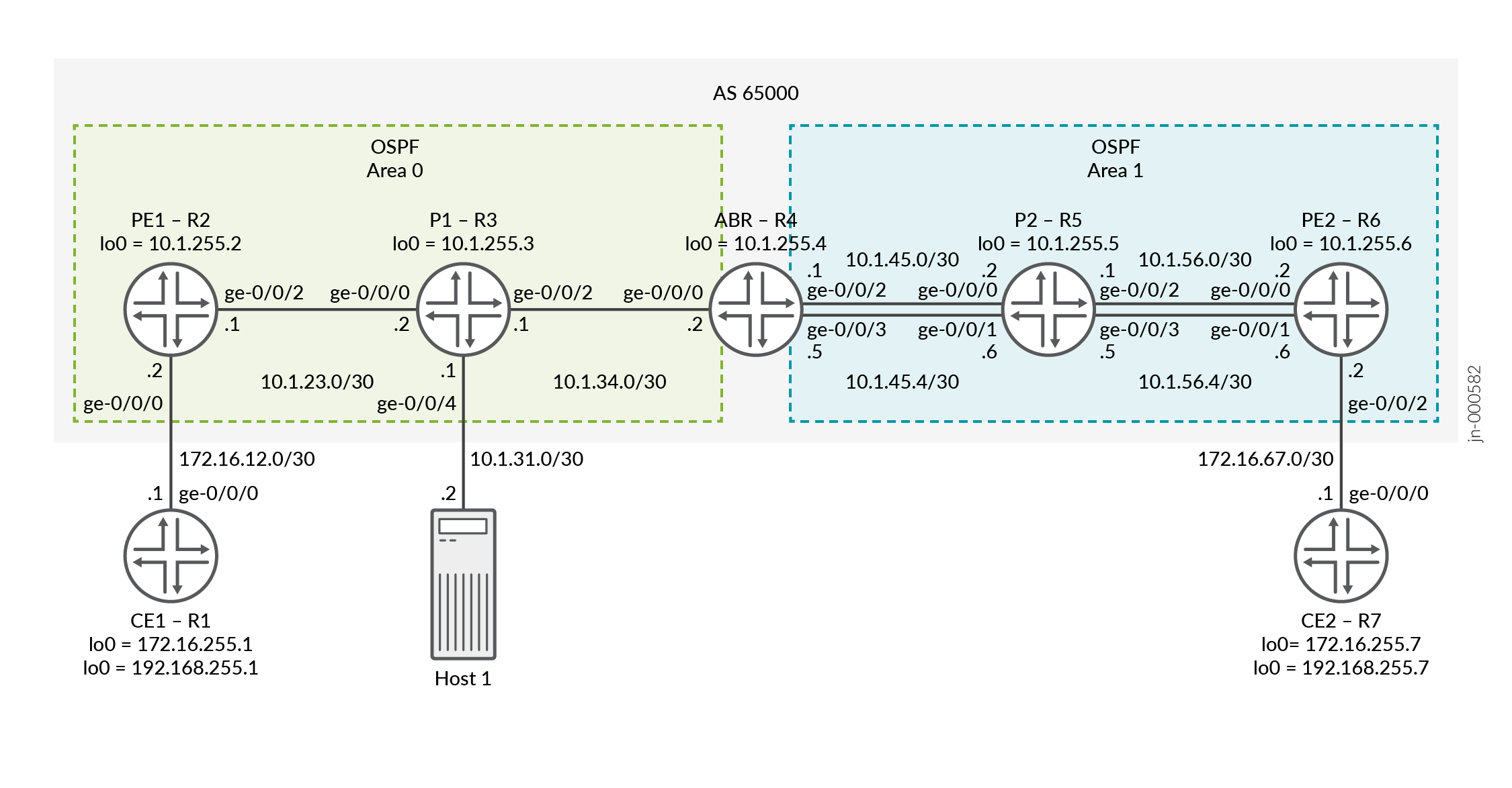 向けエントロピーラベルの設定
設定
CLIクイックコンフィグレーション
この例をすばやく設定するには、以下のコマンドをコピーしてテキストファイルに貼り付け、改行を削除し、ネットワーク設定に一致させる必要がある詳細情報を変更し、コマンドを [edit] 階層レベルでCLIにコピーアンドペーストして、設定モードから commit を入力します。
ルーターCE1
set interfaces ge-0/0/0 unit 0 family inet address 172.16.12.1/30 set interfaces lo0 unit 0 family inet address 172.16.255.1/32 primary set interfaces lo0 unit 0 family inet address 192.168.255.1/32 set routing-options router-id 172.16.255.1 set protocols ospf area 0.0.0.0 interface ge-0/0/0.0 set protocols ospf area 0.0.0.0 interface lo0.0 passive
ルーターPE1
set interfaces ge-0/0/0 unit 0 family inet address 172.16.12.2/30 set interfaces ge-0/0/2 unit 0 family inet address 10.1.23.1/30 set interfaces ge-0/0/2 unit 0 family mpls set interfaces lo0 unit 0 family inet address 10.1.255.2/32 primary set interfaces lo0 unit 1 family inet address 10.1.255.22/32 set policy-options policy-statement bgp-to-ospf from protocol bgp set policy-options policy-statement bgp-to-ospf then accept set policy-options policy-statement pplb then load-balance per-packet set routing-instances VPN-l3vpn instance-type vrf set routing-instances VPN-l3vpn protocols ospf area 0.0.0.0 interface ge-0/0/0.0 set routing-instances VPN-l3vpn protocols ospf area 0.0.0.0 interface lo0.1 passive set routing-instances VPN-l3vpn protocols ospf export bgp-to-ospf set routing-instances VPN-l3vpn interface ge-0/0/0.0 set routing-instances VPN-l3vpn interface lo0.1 set routing-instances VPN-l3vpn route-distinguisher 10.1.255.2:1 set routing-instances VPN-l3vpn vrf-target target:65000:1 set routing-options router-id 10.1.255.2 set routing-options autonomous-system 65000 set routing-options forwarding-table export pplb set protocols bgp group ibgp type internal set protocols bgp group ibgp local-address 10.1.255.2 set protocols bgp group ibgp family inet labeled-unicast entropy-label set protocols bgp group ibgp neighbor 10.1.255.4 family inet labeled-unicast rib inet.3 set protocols bgp group ibgp neighbor 10.1.255.6 family inet-vpn unicast set protocols mpls icmp-tunneling set protocols mpls label-switched-path pe1-abr to 10.1.255.4 set protocols mpls label-switched-path pe1-abr entropy-label set protocols mpls interface ge-0/0/2.0 set protocols mpls interface lo0.0 set protocols ospf traffic-engineering set protocols ospf area 0.0.0.0 interface ge-0/0/2.0 set protocols ospf area 0.0.0.0 interface lo0.0 passive set protocols rsvp interface ge-0/0/2.0 set protocols rsvp interface lo0.0
ルーターP1
set interfaces ge-0/0/0 unit 0 family inet address 10.1.23.2/30 set interfaces ge-0/0/0 unit 0 family mpls set interfaces ge-0/0/2 unit 0 family inet address 10.1.34.1/30 set interfaces ge-0/0/2 unit 0 family mpls set interfaces lo0 unit 0 family inet address 10.1.255.3/32 primary set routing-options router-id 10.1.255.3 set protocols mpls icmp-tunneling set protocols mpls interface ge-0/0/0.0 set protocols mpls interface lo0.0 set protocols mpls interface ge-0/0/2.0 set protocols ospf traffic-engineering set protocols ospf area 0.0.0.0 interface lo0.0 passive set protocols ospf area 0.0.0.0 interface ge-0/0/0.0 set protocols ospf area 0.0.0.0 interface ge-0/0/2.0 set protocols rsvp interface ge-0/0/0.0 set protocols rsvp interface lo0.0 set protocols rsvp interface ge-0/0/2.0
ルーターABR
set interfaces ge-0/0/0 unit 0 family inet address 10.1.34.2/30 set interfaces ge-0/0/0 unit 0 family mpls set interfaces ge-0/0/2 unit 0 family inet address 10.1.45.1/30 set interfaces ge-0/0/2 unit 0 family mpls set interfaces ge-0/0/3 unit 0 family inet address 10.1.45.5/30 set interfaces ge-0/0/3 unit 0 family mpls set interfaces lo0 unit 0 family inet address 10.1.255.4/32 primary set forwarding-options hash-key family mpls label-1 set forwarding-options hash-key family mpls label-2 set forwarding-options hash-key family mpls label-3 set forwarding-options enhanced-hash-key family mpls no-payload set policy-options policy-statement pplb then load-balance per-packet set policy-options policy-statement send-inet3-pe1 from route-filter 10.1.255.2/32 exact set policy-options policy-statement send-inet3-pe1 then accept set policy-options policy-statement send-inet3-pe2 from route-filter 10.1.255.6/32 exact set policy-options policy-statement send-inet3-pe2 then accept set routing-options router-id 10.1.255.4 set routing-options autonomous-system 65000 set routing-options forwarding-table export pplb set protocols bgp group ibgp type internal set protocols bgp group ibgp local-address 10.1.255.4 set protocols bgp group ibgp family inet labeled-unicast rib inet.3 set protocols bgp group ibgp neighbor 10.1.255.2 export send-inet3-pe2 set protocols bgp group ibgp neighbor 10.1.255.6 export send-inet3-pe1 set protocols mpls icmp-tunneling set protocols mpls label-switched-path abr-pe1 to 10.1.255.2 set protocols mpls label-switched-path abr-pe1 entropy-label set protocols mpls label-switched-path abr-pe2 to 10.1.255.6 set protocols mpls label-switched-path abr-pe2 entropy-label set protocols mpls label-switched-path abr-pe2 primary to-r6-1 set protocols mpls label-switched-path abr-pe2-2 to 10.1.255.6 set protocols mpls label-switched-path abr-pe2-2 entropy-label set protocols mpls label-switched-path abr-pe2-2 primary to-r6-2 set protocols mpls path to-r6-1 10.1.45.2 strict set protocols mpls path to-r6-1 10.1.56.2 strict set protocols mpls path to-r6-2 10.1.45.6 strict set protocols mpls path to-r6-2 10.1.56.6 strict set protocols mpls interface lo0.0 set protocols mpls interface ge-0/0/0.0 set protocols mpls interface ge-0/0/2.0 set protocols mpls interface ge-0/0/3.0 set protocols ospf traffic-engineering set protocols ospf area 0.0.0.0 interface lo0.0 passive set protocols ospf area 0.0.0.0 interface ge-0/0/0.0 set protocols ospf area 0.0.0.1 interface ge-0/0/2.0 set protocols ospf area 0.0.0.1 interface ge-0/0/3.0 set protocols rsvp interface lo0.0 set protocols rsvp interface ge-0/0/0.0 set protocols rsvp interface ge-0/0/2.0 set protocols rsvp interface ge-0/0/3.0
ルーターP2
set interfaces ge-0/0/0 unit 0 family inet address 10.1.45.2/30 set interfaces ge-0/0/0 unit 0 family mpls set interfaces ge-0/0/1 unit 0 family inet address 10.1.45.6/30 set interfaces ge-0/0/1 unit 0 family mpls set interfaces ge-0/0/2 unit 0 family inet address 10.1.56.1/30 set interfaces ge-0/0/2 unit 0 family mpls set interfaces ge-0/0/3 unit 0 family inet address 10.1.56.5/30 set interfaces ge-0/0/3 unit 0 family mpls set interfaces lo0 unit 0 family inet address 10.1.255.5/32 primary set forwarding-options hash-key family mpls label-1 set forwarding-options hash-key family mpls label-2 set forwarding-options hash-key family mpls label-3 set forwarding-options enhanced-hash-key family mpls no-payload set policy-options policy-statement pplb then load-balance per-packet set routing-options router-id 10.1.255.5 set routing-options forwarding-table export pplb set protocols mpls icmp-tunneling set protocols mpls interface ge-0/0/2.0 set protocols mpls interface lo0.0 set protocols mpls interface ge-0/0/0.0 set protocols mpls interface ge-0/0/1.0 set protocols mpls interface ge-0/0/3.0 set protocols ospf traffic-engineering set protocols ospf area 0.0.0.1 interface lo0.0 passive set protocols ospf area 0.0.0.1 interface ge-0/0/2.0 set protocols ospf area 0.0.0.1 interface ge-0/0/0.0 set protocols ospf area 0.0.0.1 interface ge-0/0/1.0 set protocols ospf area 0.0.0.1 interface ge-0/0/3.0 set protocols rsvp interface ge-0/0/2.0 set protocols rsvp interface lo0.0 set protocols rsvp interface ge-0/0/0.0 set protocols rsvp interface ge-0/0/1.0 set protocols rsvp interface ge-0/0/3.0
ルーターPE2
set interfaces ge-0/0/0 unit 0 family inet address 10.1.56.2/30 set interfaces ge-0/0/0 unit 0 family mpls set interfaces ge-0/0/1 unit 0 family inet address 10.1.56.6/30 set interfaces ge-0/0/1 unit 0 family mpls set interfaces ge-0/0/2 unit 0 family inet address 172.16.67.2/30 set interfaces lo0 unit 0 family inet address 10.1.255.6/32 primary set interfaces lo0 unit 1 family inet address 10.1.255.66/32 set forwarding-options hash-key family mpls label-1 set forwarding-options hash-key family mpls label-2 set forwarding-options hash-key family mpls label-3 set forwarding-options enhanced-hash-key family mpls no-payload set policy-options policy-statement bgp-to-ospf from protocol bgp set policy-options policy-statement bgp-to-ospf then accept set policy-options policy-statement pplb then load-balance per-packet set routing-instances VPN-l3vpn instance-type vrf set routing-instances VPN-l3vpn protocols ospf area 0.0.0.0 interface ge-0/0/2.0 set routing-instances VPN-l3vpn protocols ospf area 0.0.0.0 interface lo0.1 passive set routing-instances VPN-l3vpn protocols ospf export bgp-to-ospf set routing-instances VPN-l3vpn interface ge-0/0/2.0 set routing-instances VPN-l3vpn interface lo0.1 set routing-instances VPN-l3vpn route-distinguisher 10.1.255.6:1 set routing-instances VPN-l3vpn vrf-target target:65000:1 set routing-options router-id 10.1.255.6 set routing-options autonomous-system 65000 set routing-options forwarding-table export pplb set protocols bgp group ibgp type internal set protocols bgp group ibgp local-address 10.1.255.6 set protocols bgp group ibgp family inet labeled-unicast entropy-label set protocols bgp group ibgp neighbor 10.1.255.4 family inet labeled-unicast rib inet.3 set protocols bgp group ibgp neighbor 10.1.255.2 family inet-vpn unicast set protocols mpls icmp-tunneling set protocols mpls label-switched-path pe2-abr to 10.1.255.4 set protocols mpls label-switched-path pe2-abr entropy-label set protocols mpls interface ge-0/0/0.0 set protocols mpls interface lo0.0 set protocols mpls interface ge-0/0/1.0 set protocols ospf traffic-engineering set protocols ospf area 0.0.0.1 interface ge-0/0/0.0 set protocols ospf area 0.0.0.1 interface lo0.0 passive set protocols ospf area 0.0.0.1 interface ge-0/0/1.0 set protocols rsvp interface ge-0/0/0.0 set protocols rsvp interface lo0.0 set protocols rsvp interface ge-0/0/1.0
ルーターCE2
set interfaces ge-0/0/0 unit 0 family inet address 172.16.67.1/30 set interfaces lo0 unit 0 family inet address 172.16.255.7/32 primary set interfaces lo0 unit 0 family inet address 192.168.255.7/32 set routing-options router-id 172.16.255.7 set protocols ospf area 0.0.0.0 interface ge-0/0/0.0 set protocols ospf area 0.0.0.0 interface lo0.0 passive
ルーターPE1の設定
ステップバイステップの手順
次の例では、設定階層内のさまざまなレベルに移動する必要があります。CLIのナビゲーションについては、『CLIユーザーガイド』の「設定モードでのCLIエディターの使用」を参照してください。
ルーターPE1を設定するには:
適切なインターフェイス名、アドレス、およびその他のパラメーターを変更した後、ルーターPE2についてこの手順を繰り返します。
-
物理インターフェイスを設定します。コアフェーシングインターフェイスで
family mplsを設定してください。[edit] user@PE1# set interfaces ge-0/0/0 unit 0 family inet address 172.16.12.2/30 user@PE1# set interfaces ge-0/0/2 unit 0 family inet address 10.1.23.1/30 user@PE1# set interfaces ge-0/0/2 unit 0 family mpls
-
ループバックインターフェイスを設定します。セカンダリループバックはオプションであり、後のステップでルーティングインスタンスの下で適用されます。
[edit] user@PE1# set interfaces lo0 unit 0 family inet address 10.1.255.2/32 primary user@PE1# set interfaces lo0 unit 1 family inet address 10.1.255.22/32
-
ルーターIDと自律システム番号を設定します。
[edit] user@PE1# set routing-options router-id 10.1.255.2 user@PE1# set routing-options autonomous-system 65000
-
OSPFプロトコルを設定します。
[edit] user@PE1# set protocols ospf traffic-engineering user@PE1# set protocols ospf area 0.0.0.0 interface ge-0/0/2.0 user@PE1# set protocols ospf area 0.0.0.0 interface lo0.0 passive
-
RSVPプロトコルを設定します。
[edit] user@PE1# set protocols rsvp interface ge-0/0/2.0 user@PE1# set protocols rsvp interface lo0.0
-
ABRに向けてMPLSプロトコルとLSPを設定します。 エントロピーラベルをMPLSラベルスタックに追加するための
entropy-labelオプションを含めます。[edit protocols] user@PE1# set protocols mpls icmp-tunneling user@PE1# set protocols mpls label-switched-path pe1-abr to 10.1.255.4 user@PE1# set protocols mpls label-switched-path pe1-abr entropy-label user@PE1# set protocols mpls interface ge-0/0/2.0 user@PE1# set protocols mpls interface lo0.0
-
ABRピアリングには
family inet labeled-unicastを使用し、PE2ピアリングにはfamily inet-vpnを使用してIBGPを設定します。BGPラベル付きユニキャストのエントロピーラベル機能を有効にします。[edit] user@PE1# set protocols bgp group ibgp type internal user@PE1# set protocols bgp group ibgp local-address 10.1.255.2 user@PE1# set protocols bgp group ibgp family inet labeled-unicast entropy-label user@PE1# set protocols bgp group ibgp neighbor 10.1.255.4 family inet labeled-unicast rib inet.3 user@PE1# set protocols bgp group ibgp neighbor 10.1.255.6 family inet-vpn unicast
-
BGP VPNルートをOSPFにエクスポートするポリシーを定義します。ポリシーは、ルーティングインスタンスのOSPFの下で適用されます。
[edit] user@PE1# set policy-options policy-statement bgp-to-ospf from protocol bgp user@PE1# set policy-options policy-statement bgp-to-ospf then accept
-
ロードバランシングポリシーを定義し、
routing-options forwarding-tableの下にそれを適用します。この例ではPE1はパスが1つしかないため、このステップは必要ありませんが、この例では、すべてのデバイスに同じロードバランシングポリシーを適用しています。[edit] user@PE1# set policy-options policy-statement pplb then load-balance per-packet user@PE1# set routing-options forwarding-table export pplb
-
レイヤー3 VPNルーティングインスタンスを設定します。
[edit] user@PE1# set routing-instances VPN-l3vpn instance-type vrf
-
ルーティングインスタンスにインターフェイスを割り当てます。
[edit] user@PE1# set routing-instances VPN-l3vpn interface ge-0/0/0.0 user@PE1# set routing-instances VPN-l3vpn interface lo0.1
-
ルーティングインスタンスのルート識別子を設定します。
[edit] user@PE1# set routing-instances VPN-l3vpn route-distinguisher 10.1.255.2:1
-
ルーティングインスタンスのVPNルーティングおよび転送(VRF)ターゲットを設定します。
[edit] user@PE1# set routing-instances VPN-l3vpn vrf-target target:65000:1
-
ルーティングインスタンスの下でプロトコルOSPFを設定し、以前に設定された
bgp-to-ospfポリシーを適用します。[edit] user@PE1# set routing-instances VPN-l3vpn protocols ospf area 0.0.0.0 interface ge-0/0/0.0 user@PE1# set routing-instances VPN-l3vpn protocols ospf area 0.0.0.0 interface lo0.1 passive user@PE1# set routing-instances VPN-l3vpn protocols ospf export bgp-to-ospf
ルーターP1の設定
ステップバイステップの手順
次の例では、設定階層内のさまざまなレベルに移動する必要があります。CLIのナビゲーションについては、『CLIユーザーガイド』の「設定モードでのCLIエディターの使用」を参照してください。
ルーターP1を設定するには:
適切なインターフェイス名、アドレス、およびその他のパラメーターを変更した後、ルーターP2についてこの手順を繰り返します。
-
物理インターフェイスを設定します。
[edit] user@P1# set interfaces ge-0/0/0 unit 0 family inet address 10.1.23.2/30 user@P1# set interfaces ge-0/0/0 unit 0 family mpls user@P1# set interfaces ge-0/0/2 unit 0 family inet address 10.1.34.1/30 user@P1# set interfaces ge-0/0/2 unit 0 family mpls
-
ループバックインターフェイスを設定します。
[edit] user@P1# set interfaces lo0 unit 0 family inet address 10.1.255.3/32 primary
-
ルーターIDを設定します。
[edit] user@P1# set routing-options router-id 10.1.255.3
-
OSPFプロトコルを設定します。
[edit] user@P1# set protocols ospf traffic-engineering user@P1# set protocols ospf area 0.0.0.0 interface lo0.0 passive user@P1# set protocols ospf area 0.0.0.0 interface ge-0/0/0.0 user@P1# set protocols ospf area 0.0.0.0 interface ge-0/0/2.0
-
RSVPプロトコルを設定します。
[edit] user@P1# set protocols rsvp interface ge-0/0/0.0 user@P1# set protocols rsvp interface lo0.0 user@P1# set protocols rsvp interface ge-0/0/2.0
-
MPLSプロトコルを設定します。
[edit] user@P1# set protocols mpls icmp-tunneling user@P1# set protocols mpls interface ge-0/0/0.0 user@P1# set protocols mpls interface lo0.0 user@P1# set protocols mpls interface ge-0/0/2.0
ルーターABRの設定
ステップバイステップの手順
次の例では、設定階層内のさまざまなレベルに移動する必要があります。CLIのナビゲーションについては、『CLIユーザーガイド』の「設定モードでのCLIエディターの使用」を参照してください。
ルーターABRを設定するには:
-
物理インターフェイスを設定します。
[edit] user@ABR# set interfaces ge-0/0/0 unit 0 family inet address 10.1.34.2/30 user@ABR# set interfaces ge-0/0/0 unit 0 family mpls user@ABR# set interfaces ge-0/0/2 unit 0 family inet address 10.1.45.1/30 user@ABR# set interfaces ge-0/0/2 unit 0 family mpls user@ABR# set interfaces ge-0/0/3 unit 0 family inet address 10.1.45.5/30 user@ABR# set interfaces ge-0/0/3 unit 0 family mpls
-
ループバックインターフェイスを設定します。
[edit] user@ABR# set interfaces lo0 unit 0 family inet address 10.1.255.4/32 primary
-
ルーターがロードバランシングのために宛先にパケットをハッシュするために使用するMPLSラベルを設定します。
[edit] user@ABR# set forwarding-options hash-key family mpls label-1 user@ABR# set forwarding-options hash-key family mpls label-2 user@ABR# set forwarding-options hash-key family mpls label-3 user@ABR# set forwarding-options enhanced-hash-key family mpls no-payload
-
ルーターIDと自律システム番号を設定します。
[edit] user@ABR# set routing-options router-id 10.1.255.4 user@ABR# set routing-options autonomous-system 65000
-
OSPFプロトコルを設定します。
[edit] user@ABR# set protocols ospf traffic-engineering user@ABR# set protocols ospf area 0.0.0.0 interface lo0.0 passive user@ABR# set protocols ospf area 0.0.0.0 interface ge-0/0/0.0 user@ABR# set protocols ospf area 0.0.0.1 interface ge-0/0/2.0 user@ABR# set protocols ospf area 0.0.0.1 interface ge-0/0/3.0
-
RSVPプロトコルを設定します。
[edit] user@ABR# set protocols rsvp interface lo0.0 user@ABR# set protocols rsvp interface ge-0/0/0.0 user@ABR# set protocols rsvp interface ge-0/0/2.0 user@ABR# set protocols rsvp interface ge-0/0/3.0
-
MPLSプロトコルを設定し、PE1およびPE2へのLSPを指定します。異なるLSPとインターフェイスが使用されていることを示すために、トラフィックのロードバランシングを目的として、PE2に向けて2つのLSPが作成されます。
[edit] user@ABR# set protocols mpls icmp-tunneling user@ABR# set protocols mpls label-switched-path abr-pe1 to 10.1.255.2 user@ABR# set protocols mpls label-switched-path abr-pe1 entropy-label user@ABR# set protocols mpls label-switched-path abr-pe2 to 10.1.255.6 user@ABR# set protocols mpls label-switched-path abr-pe2 entropy-label user@ABR# set protocols mpls label-switched-path abr-pe2 primary to-r6-1 user@ABR# set protocols mpls label-switched-path abr-pe2-2 to 10.1.255.6 user@ABR# set protocols mpls label-switched-path abr-pe2-2 entropy-label user@ABR# set protocols mpls label-switched-path abr-pe2-2 primary to-r6-2 user@ABR# set protocols mpls path to-r6-1 10.1.45.2 strict user@ABR# set protocols mpls path to-r6-1 10.1.56.2 strict user@ABR# set protocols mpls path to-r6-2 10.1.45.6 strict user@ABR# set protocols mpls path to-r6-2 10.1.56.6 strict user@ABR# set protocols mpls interface lo0.0 user@ABR# set protocols mpls interface ge-0/0/0.0 user@ABR# set protocols mpls interface ge-0/0/2.0 user@ABR# set protocols mpls interface ge-0/0/3.0
-
family inet labeled-unicastを使用して、IBGPをPE1とPE2の両方に設定します。ポリシーを適用して、PE1とPE2の両方からinet.3ループバックルートをアドバタイズします。次のステップでポリシーを示します。[edit] user@ABR# set protocols bgp group ibgp type internal user@ABR# set protocols bgp group ibgp local-address 10.1.255.4 user@ABR# set protocols bgp group ibgp family inet labeled-unicast rib inet.3 user@ABR# set protocols bgp group ibgp neighbor 10.1.255.2 export send-inet3-pe2 user@ABR# set protocols bgp group ibgp neighbor 10.1.255.6 export send-inet3-pe1
-
PE1とPE2のループバックアドレスで一致するポリシーを定義します。
[edit] user@ABR# set policy-options policy-statement send-inet3-pe1 from route-filter 10.1.255.2/32 exact user@ABR# set policy-options policy-statement send-inet3-pe1 then accept user@ABR# set policy-options policy-statement send-inet3-pe2 from route-filter 10.1.255.6/32 exact user@ABR# set policy-options policy-statement send-inet3-pe2 then accept
-
ロードバランシングのポリシーを定義し、
routing-options forwarding-tableの下にそれを適用します。[edit] user@ABR# set policy-options policy-statement pplb then load-balance per-packet user@ABR# set routing-options forwarding-table export pplb
(オプション)ポートミラーリング設定
適用されたエントロピーラベルを表示するには、トラフィックをキャプチャできます。この例では、P1のPE1向けのインターフェイスにフィルターを適用して、CE1からCE2へのトラフィックをキャプチャします。トラフィックは、ホスト1に送信されて表示されます。この例では、トラフィックをキャプチャするさまざまな方法があります。詳細については 、ポートミラーリングとアナライザーを参照してください。
ステップバイステップの手順
次の例では、設定階層内のさまざまなレベルに移動する必要があります。CLIのナビゲーションについては、『CLIユーザーガイド』の「設定モードでのCLIエディターの使用」を参照してください。
ルーターP1を設定するには:
-
インターフェイスを設定します。この例では、Host1に接続されたインターフェイスをブリッジドメインに配置し、Host1への接続を検証するためのIRBインターフェイスを作成します。
[edit] user@P1# set interfaces ge-0/0/4 unit 0 family bridge interface-mode access user@P1# set interfaces ge-0/0/4 unit 0 family bridge vlan-id 100 user@P1# set interfaces irb unit 0 family inet address 10.1.31.1/30
-
ブリッジドメインを設定します。
[edit] user@P1# set bridge-domains v100 vlan-id 100 user@P1# set bridge-domains v100 routing-interface irb.0
-
トラフィックをキャプチャするフィルターを設定します。この例では、すべてのトラフィックをキャプチャしています。
[edit] user@P1# set firewall family any filter test term 1 then count test user@P1# set firewall family any filter test term 1 then port-mirror user@P1# set firewall family any filter test term 1 then accept
-
フィルターをPE1向けのインターフェイスに適用します。
[edit] user@P1# set interfaces ge-0/0/0 unit 0 filter input test
-
ポートミラーリングオプションを設定します。この例では、すべてのトラフィックをミラーリングし、インターフェイスge-0/0/4に接続されたHost1に送信しています。
[edit] user@P1# set forwarding-options port-mirroring input rate 1 user@P1# set forwarding-options port-mirroring family any output interface ge-0/0/4.0
検証
設定が正常に機能していることを確認します。
- エントロピーラベル機能がアドバタイズされていることの検証
- ルーターPE1がエントロピーラベルアドバタイズメントを受信することの確認
- ABRからPE2へのECMPの検証
- PE1でCE2へのルートを表示する
- CE1からCE2にPing
- ロードバランシングの検証
- エントロピーラベルの検証
エントロピーラベル機能がアドバタイズされていることの検証
目的
エントロピーラベル機能パス属性が、PE2へのルート用にABRからPE1にアドバタイズされていることを確認します。
アクション
運用モードから、ルーターABRで show route advertising-protocol bgp 10.1.255.2 detail コマンドを実行します。
user@ABR> show route advertising-protocol bgp 10.1.255.2 detail
inet.3: 2 destinations, 2 routes (2 active, 0 holddown, 0 hidden)
* 10.1.255.6/32 (1 entry, 1 announced)
BGP group ibgp type Internal
Route Label: 299952
Nexthop: Self
Flags: Nexthop Change
MED: 2
Localpref: 4294967294
AS path: [65000] I
Entropy label capable
意味
出力からは、IP アドレスが 10.1.255.6 のホスト PE2 が、エントロピーラベル機能と使用されるルートラベルを持っていることがわかります。ホストは、エントロピーラベル機能をBGPネイバーにアドバタイズしています。
ルーターPE1がエントロピーラベルアドバタイズメントを受信することの確認
目的
ルーターPE1がルーターPE2のエントロピーラベルアドバタイズメントを受信していることを確認します。
アクション
運用モードから、ルーターPE1で show route protocol bgp 10.1.255.6 extensive コマンドを実行します。
user@PE1> show route protocol bgp 10.1.255.6 extensive
inet.0: 19 destinations, 19 routes (19 active, 0 holddown, 0 hidden)
inet.3: 2 destinations, 2 routes (2 active, 0 holddown, 0 hidden)
10.1.255.6/32 (1 entry, 1 announced)
*BGP Preference: 170/1
Next hop type: Indirect, Next hop index: 0
Address: 0x7b3ffd4
Next-hop reference count: 2, key opaque handle: 0x0, non-key opaque handle: 0x0
Source: 10.1.255.4
Next hop type: Router, Next hop index: 0
Next hop: 10.1.23.2 via ge-0/0/2.0, selected
Label-switched-path pe1-abr
Label operation: Push 299952, Push 299808(top)
Label TTL action: prop-ttl, prop-ttl(top)
Load balance label: Label 299952: Entropy label; Label 299808: None;
Label element ptr: 0x93d6bf8
Label parent element ptr: 0x93d6c20
Label element references: 3
Label element child references: 2
Label element lsp id: 0
Session Id: 0
Protocol next hop: 10.1.255.4
Label operation: Push 299952
Label TTL action: prop-ttl
Load balance label: Label 299952: Entropy label;
Indirect next hop: 0x758c05c - INH Session ID: 0
State: <Active Int Ext>
Local AS: 65000 Peer AS: 65000
Age: 1:33:11 Metric: 2 Metric2: 2
Validation State: unverified
Task: BGP_65000.10.1.255.4
Announcement bits (2): 3-Resolve tree 1 4-Resolve_IGP_FRR task
AS path: I
Accepted
Route Label: 299952
Localpref: 4294967294
Router ID: 10.1.255.4
Session-IDs associated:
Session-id: 324 Version: 3
Thread: junos-main
Indirect next hops: 1
Protocol next hop: 10.1.255.4 Metric: 2 ResolvState: Resolved
Label operation: Push 299952
Label TTL action: prop-ttl
Load balance label: Label 299952: Entropy label;
Indirect next hop: 0x758c05c - INH Session ID: 0
Indirect path forwarding next hops: 1
Next hop type: Router
Next hop: 10.1.23.2 via ge-0/0/2.0
Session Id: 0
10.1.255.4/32 Originating RIB: inet.3
Metric: 2 Node path count: 1
Forwarding nexthops: 1
Next hop type: Router
Next hop: 10.1.23.2 via ge-0/0/2.0
Session Id: 0
意味
ルーターPE1は、BGPネイバーからエントロピーラベル機能アドバタイズメントを受信します。
ABRからPE2へのECMPの検証
目的
PE2への等価コストマルチパス(ECMP)を検証します。
アクション
運用モードから、ルーターABRで show route table mpls.0 と show route forwarding-table label <label>コマンドを実行します。
user@ABR> show route table mpls.0
mpls.0: 6 destinations, 6 routes (6 active, 0 holddown, 0 hidden)
+ = Active Route, - = Last Active, * = Both
0 *[MPLS/0] 2w1d 23:02:11, metric 1
Receive
1 *[MPLS/0] 2w1d 23:02:11, metric 1
Receive
2 *[MPLS/0] 2w1d 23:02:11, metric 1
Receive
13 *[MPLS/0] 2w1d 23:02:11, metric 1
Receive
299936 *[VPN/170] 2d 21:47:02
> to 10.1.34.1 via ge-0/0/0.0, label-switched-path abr-pe1
299952 *[VPN/170] 2d 21:47:02
> to 10.1.45.2 via ge-0/0/2.0, label-switched-path abr-pe2
to 10.1.45.6 via ge-0/0/3.0, label-switched-path abr-pe2-2
ruser@ABR> show route forwarding-table label 299952
Routing table: default.mpls
MPLS:
Destination Type RtRef Next hop Type Index NhRef Netif
299952 user 0 ulst 1048575 2
10.1.45.2 Swap 299824 516 2 ge-0/0/2.0
10.1.45.6 Swap 299840 572 2 ge-0/0/3.0
...
意味
出力は、BGPラベル付きユニキャストルートに使用されるラベルのECMPを示しています。
PE1でCE2へのルートを表示する
目的
CE2へのルートを確認します。
アクション
運用モードから、ルーターPE1で show route table VPN-l3vpn.inet.0 172.16.255.7 extensive コマンドと show route table VPN-l3vpn.inet.0 192.168.255.7 extensiveコマンドを実行します。
user@PE1> show route table VPN-l3vpn.inet.0 172.16.255.7 extensive
VPN-l3vpn.inet.0: 10 destinations, 10 routes (10 active, 0 holddown, 0 hidden)
172.16.255.7/32 (1 entry, 1 announced)
TSI:
OSPF area : 0.0.0.0, LSA ID : 172.16.255.7, LSA type : Summary
KRT in-kernel 172.16.255.7/32 -> {indirect(1048574)}
*BGP Preference: 170/-101
Route Distinguisher: 10.1.255.6:1
Next hop type: Indirect, Next hop index: 0
Address: 0x7b40434
Next-hop reference count: 9, key opaque handle: 0x0, non-key opaque handle: 0x0
Source: 10.1.255.6
Next hop type: Router, Next hop index: 515
Next hop: 10.1.23.2 via ge-0/0/2.0, selected
Label-switched-path pe1-abr
Label operation: Push 299824, Push 299952, Push 299808(top)
Label TTL action: prop-ttl, prop-ttl, prop-ttl(top)
Load balance label: Label 299824: None; Label 299952: Entropy label; Label 299808: None;
Label element ptr: 0x93d6c98
Label parent element ptr: 0x93d6bf8
Label element references: 1
Label element child references: 0
Label element lsp id: 0
Session Id: 140
Protocol next hop: 10.1.255.6
Label operation: Push 299824
Label TTL action: prop-ttl
Load balance label: Label 299824: None;
...
user@PE1> show route table VPN-l3vpn.inet.0 192.168.255.7 extensive
VPN-l3vpn.inet.0: 10 destinations, 10 routes (10 active, 0 holddown, 0 hidden)
192.168.255.7/32 (1 entry, 1 announced)
TSI:
OSPF area : 0.0.0.0, LSA ID : 192.168.255.7, LSA type : Summary
KRT in-kernel 192.168.255.7/32 -> {indirect(1048574)}
*BGP Preference: 170/-101
Route Distinguisher: 10.1.255.6:1
Next hop type: Indirect, Next hop index: 0
Address: 0x7b40434
Next-hop reference count: 9, key opaque handle: 0x0, non-key opaque handle: 0x0
Source: 10.1.255.6
Next hop type: Router, Next hop index: 515
Next hop: 10.1.23.2 via ge-0/0/2.0, selected
Label-switched-path pe1-abr
Label operation: Push 299824, Push 299952, Push 299808(top)
Label TTL action: prop-ttl, prop-ttl, prop-ttl(top)
Load balance label: Label 299824: None; Label 299952: Entropy label; Label 299808: None;
Label element ptr: 0x93d6c98
Label parent element ptr: 0x93d6bf8
Label element references: 1
Label element child references: 0
Label element lsp id: 0
Session Id: 140
Protocol next hop: 10.1.255.6
Label operation: Push 299824
Label TTL action: prop-ttl
Load balance label: Label 299824: None;
...
意味
出力からは、両方のルートに同じラベルが使用されていることがわかります。
CE1からCE2にPing
目的
接続を確認し、ロードバランシングの検証に使用します。
アクション
運用モードから、ルーターPE1で ping 172.16.255.7 source 172.16.12.1 rapid count 100 コマンドと ping 192.168.255.7 source 192.168.255.1 rapid count 200コマンドを実行します。
user@CE1> ping 172.16.255.7 source 172.16.12.1 rapid count 100 PING 172.16.255.7 (172.16.255.7): 56 data bytes !!!!!!!!!!!!!!!!!!!!!!!!!!!!!!!!!!!!!!!!!!!!!!!!!!!!!!!!!!!!!!!!!!!!!!!!!!!!!!!!!!!!!!!!!!!!!!!!!!!! --- 172.16.255.7 ping statistics --- 100 packets transmitted, 100 packets received, 0% packet loss round-trip min/avg/max/stddev = 5.369/6.070/8.828/0.612 ms user@CE1> ping 192.168.255.7 source 192.168.255.1 rapid count 200 PING 192.168.255.7 (192.168.255.7): 56 data bytes !!!!!!!!!!!!!!!!!!!!!!!!!!!!!!!!!!!!!!!!!!!!!!!!!!!!!!!!!!!!!!!!!!!!!!!!!!!!!!!!!!!!!!!!!!!!!!!!!!!!!!!!!!!!!!!!!!!!!!!!!!!!!!!!!!!!!!!!!!!!!!!!!!!!!!!!!!!!!!!!!!!!!!!!!!!!!!!!!!!!!!!!!!!!!!!!!!!!!!!! --- 192.168.255.7 ping statistics --- 200 packets transmitted, 200 packets received, 0% packet loss round-trip min/avg/max/stddev = 5.086/5.994/10.665/0.649 ms
意味
出力からは、pingsが成功したことがわかります。
ロードバランシングの検証
目的
ロードバランシングを検証します。
アクション
運用モードから、ABRで show mpls lsp ingress statistics コマンドを実行します。
user@ABR> show mpls lsp ingress statistics Ingress LSP: 3 sessions To From State Packets Bytes LSPname 10.1.255.2 10.1.255.4 Up 300 30000 abr-pe1 10.1.255.6 10.1.255.4 Up 200 20000 abr-pe2 10.1.255.6 10.1.255.4 Up 100 10000 abr-pe2-2 Total 3 displayed, Up 3, Down 0
意味
出力からは、前のコマンドからの1番目のpingはLSP abr-pe2-2 を、2番目のpingはLSP abr-pe2を使ったことがわかります。
エントロピーラベルの検証
目的
エントロピーラベルが使用されたping間で異なっていることを確認します。
アクション
ホスト1で、 tcpdump -i eth1 -nを実行します。
user@Host1# tcpdump -i eth1 -n ... 13:42:31.993274 MPLS (label 299808, exp 0, ttl 63) (label 299952, exp 0, ttl 63) (label 7, exp 0, ttl 63) (label 1012776, exp 0, ttl 0) (label 299824, exp 0, [S], ttl 63) IP 172.16.12.1 > 172.16.255.7: ICMP echo request, id 32813, seq 9, length 64 ... 13:43:19.570260 MPLS (label 299808, exp 0, ttl 63) (label 299952, exp 0, ttl 63) (label 7, exp 0, ttl 63) (label 691092, exp 0, ttl 0) (label 299824, exp 0, [S], ttl 63) IP 192.168.255.1 > 192.168.255.7: ICMP echo request, id 46381, seq 9, length 64
意味
出力には、2つの異なるpingコマンドのエントロピーラベルの異なる値が表示されます。
Inet、Inet6、またはラベル付きユニキャストの BGP プレフィックス独立コンバージェンスの使用例
ルーターに障害が発生した場合、ネットワークの規模やルーターのパフォーマンスなどのパラメーターによって、BGPネットワークの復元に数秒から数分かかることがあります。ルーターでBGPプレフィックス独立コンバージェンス(PIC)機能が有効になっている場合、BGPは計算された最適なパスを宛先にインストールするのに加え、2番目に最適なパスをパケット転送エンジンにインストールします。ネットワークでegressルーターに障害が発生し、停止時間が大幅に短縮された場合、ルーターはこのバックアップパスを使用します。この機能を有効にして、egressルーターに障害が発生した場合のネットワークダウンタイムを短縮できます。
ネットワーク内のegressルーターへの到達可能性が損なわれると、IGPがこの障害を検出し、リンク状態がこの情報をネットワーク全体に伝播し、そのプレフィックスのBGPネクストホップを到達不能としてアドバタイズします。BGPは代替パスを再評価し、代替パスが利用可能な場合は、この代替ネクストホップをパケット転送エンジンに再インストールします。このようなイグレス障害は通常、複数のプレフィックスに同時に影響を及ぼし、BGPはこれらのプレフィックスすべてを一度に1つずつ更新する必要があります。イングレスルーターでは、IGPはショーテストパスファースト(SPF)を完了し、ネクストホップを更新します。次に、Junos OS が到達不能になったプレフィックスと、これらを更新する必要があるプロトコルにシグナルを送ります。BGPは通知を受信し、現在無効なすべてのプレフィックスに対してネクストホップを更新します。このプロセスは接続に影響を与える可能性があり、障害から回復するのに数分かかる可能性があります。バックアップ パスがすでにパケット転送エンジンにインストールされているため、BGP PIC はこのダウンタイムを短縮できます。
Junos OS リリース 15.1 以降、当初レイヤー 3 VPN ルーターでサポートされていた BGP PIC 機能が、inet および inet6 ユニキャスト、inet および inet6 ラベル付きユニキャストなど、グローバル テーブルに複数のルートがある BGP に拡張されています。BGP PIC対応ルーターでは、Junos OSはルーティングエンジンに間接ネクストホップのバックアップパスをインストールし、このルートをパケット転送エンジンとIGPに提供します。IGPは、1つ以上の経路を持つプレフィックスへの到達性を失うと、ルーティングテーブルを更新する前に、1つのメッセージでルーティングエンジンに信号を送ります。ルーティングエンジンは、間接ネクストホップに障害が発生したことをパケット転送エンジンに通知し、バックアップパスを使用してトラフィックを再ルーティングする必要があります。影響を受けた宛先プレフィックスへのルーティングは、BGPがBGPプレフィックスの新しいネクストホップの再計算を開始する前でも、バックアップパスを使用してBGPパスを使用して続行されます。ルーターは、BGPを介したグローバルコンバージェンスが解決されるまで、このバックアップパスを使用してトラフィックロスを低減します。
障害が発生してから到達可能性の損失がシグナルされるまでの時間は、実際には、最も近いルーターの障害検出時間とIGPコンバージェンス時間に依存します。ローカルルーターが障害を検出すると、BGP PIC機能が有効になっていないルートコンバージェンスは、影響を受けるプレフィックスの数と、影響を受けた各プレフィックスの再計算によるルーターのパフォーマンスに大きく依存します。ただし、BGP PIC 機能を有効にすると、BGP が影響を受けたプレフィックスに最適なパスを再計算する前でも、ルーティングエンジンはスタンバイの次善パスに切り替えるようデータプレーンにシグナルします。そのため、トラフィックの損失は最小限に抑えられます。新しいルートは、トラフィックが転送されていても計算され、これらの新しいルートはデータ プレーンにプッシュ ダウンされます。そのため、影響を受けたBGPプレフィックスの数は、トラフィック障害から発生してからBGPが到達可能性の喪失をシグナルするまでの時間には影響しません。
関連項目
InetのBGPプレフィックス独立コンバージェンスの設定
BGPプレフィックス独立コンバージェンス(PIC)が有効なルーターでは、Junos OSはルーティングエンジンに間接ネクストホップのバックアップパスをインストールし、このルートをパケット転送エンジンとIGPに提供します。IGPは、1つ以上の経路を持つプレフィックスへの到達性を失うと、ルーティングテーブルを更新する前に、1つのメッセージでルーティングエンジンに信号を送ります。ルーティングエンジンは、間接ネクストホップに障害が発生したことをパケット転送エンジンに通知し、バックアップパスを使用してトラフィックを再ルーティングする必要があります。影響を受けた宛先プレフィックスへのルーティングは、BGPがBGPプレフィックスの新しいネクストホップの再計算を開始する前でも、バックアップパスを使用してBGPパスを使用して続行されます。ルーターは、BGPを介したグローバルコンバージェンスが解決されるまで、このバックアップパスを使用してトラフィックロスを低減します。当初レイヤー3 VPNルーターでサポートされていたBGP PIC機能は、inetとinet6のユニキャスト、inetとinet6のラベル付きユニキャストなど、グローバルテーブルに複数のルートを持つBGPに拡張されました。
始める前に:
デバイスインターフェイスを設定します。
OSPFまたはその他のIGPプロトコルを設定します。
MPLSとLDPを設定します。
BGPを設定します。
BGP PIC 機能は、MPC インターフェイスを持つルーターでのみサポートされます。
モジュラーポートコンセントレータ(MPC)を搭載したルーターでは、次に示すように、拡張IPネットワークサービスを有効にします。
[edit chassis network-services] user@host# set enhanced-ip
inet に BGP PIC を設定するには:
関連項目
例:InetのBGPプレフィックス独立コンバージェンスの設定
この例では、inet に BGP PIC を設定する方法を示します。ルーターに障害が発生した場合、ネットワークの規模やルーターのパフォーマンスなどのパラメーターによって、BGPネットワークの復元に数秒から数分かかることがあります。ルーターでBGPプレフィックス独立コンバージェンス(PIC)機能が有効になっている場合、inetとinet6ユニキャスト、inetとinet6ラベル付けユニキャストなど、グローバルテーブルに複数のルートを持つBGPは、計算された宛先への最適なパスに加えて、2番目に良いパスをパケット転送エンジンにインストールします。ネットワークでegressルーターに障害が発生し、停止時間が大幅に短縮された場合、ルーターはこのバックアップパスを使用します。
要件
この例を設定する前に、デバイスの初期化以外の特別な設定を行う必要はありません。
この例では、以下のハードウェアおよびソフトウェアコンポーネントを使用しています。
-
BGP PIC機能を設定するためのMPC搭載のMXシリーズルーター1台
-
M Series、MXシリーズ、T Series、またはPTXシリーズルーターの組み合わせが可能な7台のルーター
-
BGP PICが設定されたデバイスでのJunos OSリリース15.1以降
概要
Junos OSリリース15.1以降、当初レイヤー3 VPNルーターでサポートされていたBGP PICは、inetおよびinet6ユニキャスト、inetおよびinet6ラベル付きユニキャストなどのグローバルテーブルに複数のルートを持つBGPに拡張されます。BGPは、計算された最適なパスを宛先にインストールするのに加え、2番目に最適なパスをパケット転送エンジンにインストールします。IGPがプレフィックスへの到達性を失うと、ルーターはこのバックアップパスを使用して、BGPを介したグローバルコンバージェンスが解決されるまでトラフィックの損失を減らすことで、停止期間を短縮します。
BGP PIC機能は、MPCを搭載したルーターでのみサポートされています。
トポロジー
この例では、デバイスCE0、CE1、およびCE2の3台のカスタマーエッジ(CE)ルーターを示しています。ルーターPE0、PE1、およびPE2は、プロバイダーエッジ(PE)ルーターです。ルーターP0とP1は、プロバイダーのコアルーターです。BGP PICはルーターPE0に設定されています。テストのために、アドレス192.168.1.5がデバイスCE1に2番目のループバックインターフェイスアドレスとして追加されます。このアドレスはルーターPE1とPE2に通知され、内部BGP(IBGP)によってルーターPE0に中継されます。ルーターPE0には、192.168.1.5ネットワークへの2つのパスがあります。これらは、プライマリーパスとバックアップパスです。 図13 は、サンプルネットワークを示しています。
 向けBGP PICの設定
設定
CLIクイックコンフィグレーション
この例を迅速に設定するには、以下のコマンドをコピーしてテキストファイルに貼り付け、改行を削除し、ネットワーク設定に一致させる必要がある詳細情報を変更し、コマンドを [edit] 階層レベルでCLIにコピーアンドペーストして、設定モードからコミットを入力します。
ルーターPE0
set chassis network-services enhanced-ip set interfaces ge-0/0/0 unit 0 description PE0->P0 set interfaces ge-0/0/0 unit 0 family inet address 10.0.0.5/24 set interfaces ge-0/0/0 unit 0 family iso set interfaces ge-0/0/0 unit 0 family inet6 address 2001:db8::1/32 set interfaces ge-0/0/0 unit 0 family mpls set interfaces ge-0/0/1 unit 0 description PE0->P1 set interfaces ge-0/0/1 unit 0 family inet address 10.0.0.1/24 set interfaces ge-0/0/1 unit 0 family iso set interfaces ge-0/0/1 unit 0 family inet6 address 2001:db8::2/32 set interfaces ge-0/0/1 unit 0 family mpls set interfaces lo0 unit 0 family inet address 192.168.0.1/32 set interfaces ge-0/0/2 unit 0 description PE0->CE0 set interfaces ge-0/0/2 unit 0 family inet address 172.16.0.1/30 set interfaces ge-0/0/2 unit 0 family inet6 address 2001:db8::10/32 set interfaces ge-0/0/2 unit 0 family mpls set protocols mpls ipv6-tunneling set protocols mpls interface all set protocols mpls interface fxp0.0 disable set protocols bgp group ibgp type internal set protocols bgp group ibgp local-address 192.168.0.1 set protocols bgp group ibgp family inet labeled-unicast per-prefix-label set protocols bgp group ibgp family inet6 labeled-unicast explicit-null set protocols bgp group ibgp export nhself set protocols bgp group ibgp neighbor 192.168.0.4 description PE1 set protocols bgp group ibgp neighbor 192.168.0.5 description PE2 set protocols bgp group ebgp type external set protocols bgp group ebgp local address 192.168.0.1 set protocols bgp group ebgp family inet labeled-unicast set protocols bgp group ebgp family inet6 labeled-unicast set protocols bgp group ebgp peer-as 64497 set protocols bgp group ebgp neighbor 172.16.0.2 description CE0 set protocols ospf area 0.0.0.0 interface all set protocols ospf area 0.0.0.0 interface fxp0.0 disable set protocols ospf area 0.0.0.0 interface lo0.0 passive set protocols ospf area 0.0.0.0 interface ge-0/0/1.0 metric 1000 set protocols ospf3 area 0.0.0.0 interface all set protocols ospf3 area 0.0.0.0 interface fxp0.0 disable set protocols ospf3 area 0.0.0.0 interface lo0.0 passive set protocols ospf3 area 0.0.0.0 interface ge-0/0/1.0 metric 1000 set protocols ldp track-igp-metric set protocols ldp interface all set protocols ldp interface fxp0.0 disable set policy-options policy-statement lb then load-balance per-packet set policy-options policy-statement nhself then next-hop self set routing-options protect core set routing-options forwarding-table export lb set routing-options router-id 192.168.0.1 set routing-options autonomous-system 64496
ルーターP0
set chassis network-services enhanced-ip set interfaces ge-0/0/0 unit 0 description P0->PE0 set interfaces ge-0/0/0 unit 0 family inet address 10.0.0.6/24 set interfaces ge-0/0/0 unit 0 family inet6 address 2001:db8::3/32 set interfaces ge-0/0/0 unit 0 family mpls set interfaces ge-0/0/1 unit 0 description P0->PE1 set interfaces ge-0/0/1 unit 0 family inet address 10.0.0.9/24 set interfaces ge-0/0/1 unit 0 family inet6 address 2001:db8::4/32 set interfaces ge-0/0/1 unit 0 family mpls set interfaces lo0 unit 0 family inet address 192.168.0.2/32 set protocols ospf area 0.0.0.0 interface all set protocols ospf area 0.0.0.0 interface fxp0.0 disable set protocols ospf area 0.0.0.0 interface lo0.0 passive set protocols bgp group ibgp type internal set protocols bgp group ibgp local address 192.168.0.1 set protocols bgp group ibgp neighbor 192.168.0.4 description PE1 set protocols bgp group ibgp neighbor 192.168.0.5 description PE2 set routing-options router-id 192.168.0.2 set routing-options autonomous-system 64496
ルーターP1
set chassis network-services enhanced-ip set interfaces ge-0/0/1 unit 0 description P1->PE0 set interfaces ge-0/0/1 unit 0 family inet address 10.0.0.2/24 set interfaces ge-0/0/1 unit 0 family inet6 address 2001:db8::5/32 set interfaces ge-0/0/1 unit 0 family mpls set interfaces ge-0/0/0 unit 0 description P1->PE2 set interfaces ge-0/0/0 unit 0 family inet address 10.0.0.13/24 set interfaces ge-0/0/0 unit 0 family inet6 address 2001:db8::6/32 set interfaces ge-0/0/0 unit 0 family mpls set interfaces lo0 unit 0 family inet address 192.168.0.3/32 set protocols ospf area 0.0.0.0 interface all set protocols ospf area 0.0.0.0 interface fxp0.0 disable set protocols ospf area 0.0.0.0 interface lo0.0 passive set protocols bgp group ibgp type internal set protocols bgp group ibgp local address 192.168.0.3 set protocols bgp group ibgp neighbor 192.168.0.1 description PE0 set protocols bgp group ibgp neighbor 192.168.0.5 description PE2 set routing-options router-id 192.168.0.3 set routing-options autonomous-system 64496
ルーターPE1
set chassis network-services enhanced-ip set interfaces ge-0/0/0 unit 0 description PE1->P0 set interfaces ge-0/0/0 unit 0 family inet address 10.0.0.10/24 set interfaces ge-0/0/0 unit 0 family inet6 address 2001:db8::7/32 set interfaces ge-0/0/0 unit 0 family mpls set interfaces ge-0/0/0 unit 0 family iso set interfaces ge-0/0/1 unit 0 description PE1->CE1 set interfaces ge-0/0/1 unit 0 family inet address 172.16.1.1/30 set interfaces ge-0/0/1 unit 0 family inet6 address 2001:db8::12/32 set interfaces ge-0/0/1 unit 0 family mpls set interfaces lo0 unit 0 family inet address 192.168.0.4/32 set protocols bgp group ibgp type internal set protocols bgp group ibgp local address 192.168.0.4 set protocols bgp group ibgp family inet labeled-unicast per-prefix-label set protocols bgp group ibgp family inet6 labeled-unicast explicit-null set protocols bgp group ibgp export nhself set protocols bgp group ibgp neighbor 192.168.0.1 description PE0 set protocols bgp group ibgp neighbor 192.168.0.5 description PE2 set protocols bgp group ebgp type external set protocols bgp group ebgp local address 192.168.0.4 set protocols bgp group ebgp peer-as 64497 set protocols bgp group ebgp neighbor 172.16.1.2 description CE1 set protocols ospf area 0.0.0.0 interface all set protocols ospf area 0.0.0.0 interface fxp0.0 disable set protocols ospf area 0.0.0.0 interface lo0.0 passive set protocols ospf area 0.0.0.0 interface ge-0/0/1.0 metric 1000 set protocols ospf3 area 0.0.0.0 interface all set protocols ospf3 area 0.0.0.0 interface fxp0.0 disable set protocols ospf3 area 0.0.0.0 interface lo0.0 passive set protocols ospf3 area 0.0.0.0 interface ge-0/0/0.0 metric 1000 set protocols ldp track-igp-metric set protocols ldp interface all set protocols ldp interface fxp0.0 disable set policy-options policy-statement PE1-v6-nh_CE1 from family inet6 set policy-options policy-statement PE1-v6-nh_CE1 then next-hop 2001:DB8::13 set policy-options policy-statement nhself then next-hop self set routing-options router-id 192.168.0.4 set routing-options autonomous-system 64496 set routing-options static route 192.168.1.2 next-hop 172.16.1.2
ルーターPE2
set chassis network-services enhanced-ip set interfaces ge-0/0/0 unit 0 description PE2->P1 set interfaces ge-0/0/0 unit 0 family inet address 10.0.0.14/24 set interfaces ge-0/0/0 unit 0 family inet6 address 2001:db8::8/32 set interfaces ge-0/0/0 unit 0 family mpls set interfaces ge-0/0/0 unit 0 family iso set interfaces ge-0/0/1 unit 0 description PE2->CE2 set interfaces ge-0/0/1 unit 0 family inet address 172.16.2.1/30 set interfaces ge-0/0/1 unit 0 family inet6 address 2001:db8::14/32 set interfaces ge-0/0/1 unit 0 family mpls set interfaces lo0 unit 0 family inet address 192.168.0.5/32 set protocols mpls ipv6-tunneling set protocols mpls interface all set protocols mpls interface fxp0.0 disable set protocols bgp group ibgp type internal set protocols bgp group ibgp local address 192.168.0.5 set protocols bgp group ibgp family inet labeled-unicast per-prefix-label set protocols bgp group ibgp family inet6 labeled-unicast explicit-null set protocols bgp group ibgp export nhself set protocols bgp group ibgp neighbor 192.168.0.4 description PE1 set protocols bgp group ibgp neighbor 192.168.0.1 description PE0 set protocols bgp group ebgp type external set protocols bgp group ebgp local address 192.168.0.5 set protocols bgp group ebgp peer-as 64497 set protocols bgp group ebgp family inet labeled-unicast set protocols bgp group ebgp family inet6 labeled-unicast set protocols bgp group ebgp neighbor 172.16.2.2 description CE2 set protocols ospf area 0.0.0.0 interface all set protocols ospf area 0.0.0.0 interface fxp0.0 disable set protocols ospf area 0.0.0.0 interface lo0.0 passive set protocols ospf area 0.0.0.0 interface ge-0/0/1.0 metric 1000 set protocols ospf3 area 0.0.0.0 interface all set protocols ospf3 area 0.0.0.0 interface fxp0.0 disable set protocols ospf3 area 0.0.0.0 interface lo0.0 passive set protocols ospf3 area 0.0.0.0 interface ge-0/0/0.0 metric 1000 set protocols ldp track-igp-metric set protocols ldp interface all set protocols ldp interface fxp0.0 disable set policy-options policy-statement nhself then next-hop self set routing-options router-id 192.168.0.5 set routing-options autonomous-system 64496 set routing-options static route 192.168.1.3 next-hop 172.16.2.2
デバイスCE0
set chassis network-services enhanced-ip set interfaces ge-0/0/2 unit 0 description CE0->PE0 set interfaces ge-0/0/2 unit 0 family inet address 172.16.0.2/30 set interfaces ge-0/0/2 unit 0 family inet6 address 2001:db8::11/32 set interfaces lo0 unit 0 family inet address 192.168.1.1/32 set protocols mpls interface all set protocols bgp group ebgp type external set protocols bgp group ebgp peer-as 64496 set protocols bgp group ebgp family inet labeled-unicast set protocols bgp group ebgp family inet6 labeled-unicast set protocols bgp group ebgp neighbor 172.16.0.1 description PE0 set protocols bgp group ebgp local-address 192.168.1.1 set routing-options autonomous-system 64497 set routing-options router-id 192.168.1.1
デバイスCE1
set chassis network-services enhanced-ip set interfaces ge-0/0/2 unit 0 description CE1->PE1 set interfaces ge-0/0/2 unit 0 family inet address 172.16.1.2/30 set interfaces ge-0/0/2 unit 0 family inet6 address 2001:db8::13/32 set interfaces ge-0/0/2 unit 0 family mpls set interfaces lo0 unit 0 family inet address 192.168.1.2/32 set interfaces lo0 unit 0 family inet address 192.168.1.5/24 set protocols mpls interface all set protocols bgp group ebgp type external set protocols bgp group ebgp peer-as 64496 set protocols bgp group ebgp family inet labeled-unicast set protocols bgp group ebgp family inet6 labeled-unicast set protocols bgp group ebgp export send-direct set protocols bgp group ebgp neighbor 172.16.1.1 description PE1 set policy-options policy statement send-direct from protocol direct then accept set routing-options autonomous-system 64497 set routing-options router-id 192.168.1.2
デバイスCE2
set chassis network-services enhanced-ip set interfaces ge-0/0/2 unit 0 description CE2->PE2 set interfaces ge-0/0/2 unit 0 family inet address 172.16.2.2/30 set interfaces ge-0/0/2 unit 0 family inet6 address 2001:db8::15/32 set interfaces ge-0/0/2 unit 0 family mpls set interfaces lo0 unit 0 family inet address 192.168.1.3/32 set protocols mpls interface all set protocols bgp group ebgp type external set protocols bgp group ebgp peer-as 64496 set protocols bgp group ebgp family inet labeled-unicast set protocols bgp group ebgp family inet6 labeled-unicast set protocols bgp group ebgp export send-direct set protocols bgp group ebgp neighbor 172.16.2.1 description PE2 set policy-options policy statement send-direct from protocol direct then accept set routing-options autonomous-system 64497 set routing-options router-id 192.168.1.3
デバイスPE0の設定
ステップバイステップの手順
次の例では、設定階層内のさまざまなレベルに移動する必要があります。CLIのナビゲーションについては、『Junos OS CLIユーザーガイド』の「設定モードでのCLIエディターの使用」を参照してください。
デバイスPE0を設定するには:
-
MPC(モジュラーポートコンセントレータ)を搭載したルーターで、拡張IPネットワークサービスを有効にします。
[edit chassis] usr@PE0# set network-services enhanced-ip -
デバイスインターフェイスを設定します。
[edit interfaces] user@PE0# set ge-0/0/0 unit 0 description PE0->P0 user@PE0# set ge-0/0/0 unit 0 family inet address 10.0.0.5/24 user@PE0# set ge-0/0/0 unit 0 family iso user@PE0# set ge-0/0/0 unit 0 family inet6 address 2001:db8::1/32 user@PE0# set ge-0/0/0 unit 0 family mpls user@PE0# set ge-0/0/1 unit 0 description PE0->P1 user@PE0# set ge-0/0/1 unit 0 family inet address 10.0.0.1/24 user@PE0# set ge-0/0/1 unit 0 family iso user@PE0# set ge-0/0/1 unit 0 family inet6 address 2001:db8::2/32 user@PE0# set ge-0/0/1 unit 0 family mpls user@PE0# set ge-0/0/2 unit 0 description PE0->CE0 user@PE0# set ge-0/0/2 unit 0 family inet address 172.16.0.1/30 user@PE0# set ge-0/0/2 unit 0 family inet6 address 2001:db8::10/32 user@PE0# set ge-0/0/2 unit 0 family mpls
-
ループバックインターフェイスを設定します。
[edit interfaces] user@PE0# set lo0 unit 0 family inet address 192.168.0.1/32
-
管理インターフェイスを除くすべてのインターフェイスで MPLS と LDP を設定します。
[edit protocols] user@PE0# set mpls ipv6-tunneling user@PE0# set mpls interface all user@PE0# set mpls interface fxp0.0 disable user@PE0# set ldp track-igp-metric user@PE0# set ldp interface all user@PE0# set ldp interface fxp0.0 disable
-
コアに面するインターフェイスでIGPを設定します。
[edit protocols] user@PE0# set ospf area 0.0.0.0 interface all user@PE0# set ospf area 0.0.0.0 interface fxp0.0 disable user@PE0# set ospf area 0.0.0.0 interface lo0.0 passive user@PE0# set ospf area 0.0.0.0 interface ge-0/0/1.0 metric 1000 user@PE0# set ospf3 area 0.0.0.0 interface all user@PE0# set ospf3 area 0.0.0.0 interface fxp0.0 disable user@PE0# set ospf3 area 0.0.0.0 interface lo0.0 passive user@PE0# set ospf3 area 0.0.0.0 interface ge-0/0/1.0 metric 1000
-
他のPEデバイスとのIBGP接続を設定します。
[edit protocols] user@PE0# set bgp group ibgp type internal user@PE0# set bgp group ibgp local-address 192.168.0.1 user@PE0# set bgp group ibgp family inet labeled-unicast per-prefix-label user@PE0# set bgp group ibgp family inet6 labeled-unicast explicit-null user@PE0# set bgp group ibgp export nhself user@PE0# set bgp group ibgp neighbor 192.168.0.4 description PE1 user@PE0# set bgp group ibgp neighbor 192.168.0.5 description PE2
-
顧客デバイスとのEBGP接続を設定します。
[edit protocols] user@PE0# set bgp group ebgp type external user@PE0# set bgp group ebgp local address 192.168.0.1 user@PE0# set bgp group ebgp family inet labeled-unicast user@PE0# set bgp group ebgp family inet6 labeled-unicast user@PE0# set bgp group ebgp peer-as 64497 user@PE0# set bgp group ebgp neighbor 172.16.0.2 description CE0
-
負荷分散ポリシーを設定します。
[edit policy-options] user@PE0# set policy-statement lb then load-balance per-packet
-
ネクストホップ自己ポリシーを設定します。
[edit policy-options] user@PE0# set policy-statement nhself then next-hop self
-
BGP PICエッジ機能を有効にします。
[edit routing-options] user@PE0# set protect core
-
負荷分散ポリシーを適用します。
[edit routing-options] user@PE0# set forwarding-table export lb
-
ルーターIDと自律システム(AS)番号を割り当てます。
[edit routing-options] user@PE0# set router-id 192.168.0.2 user@PE0# set autonomous-system 64496
結果
設定モードから、 show chassis、 show interfaces、 show protocols、 show policy-options、 show routing-options コマンドを入力して設定を確認します。出力に意図した設定が表示されない場合は、この例の手順を繰り返して設定を修正します。
[edit] user@PE0# show chassis network-services enhanced-ip;
[edit]
user@PE0# show interfaces
ge-0/0/0 {
unit 0 {
description PE0->P0;
family inet {
address 10.0.0.5/24;
}
family iso;
family inet6 {
address 2001:db8::1/32;
}
family mpls;
}
}
ge-0/0/1 {
unit 0 {
description PE0->P1;
family inet {
address 10.0.0.1/24;
}
family iso;
family inet6 {
address 2001:db8::2/32;
}
family mpls;
}
}
ge-0/0/2 {
unit 0 {
description PE0->CE0;
family inet {
address 172.16.0.1/30;
}
family inet6 {
address 2001:db8::10/32;
}
family mpls;
}
}
lo0 {
unit 0 {
family inet {
address 192.168.0.1/32;
}
}
}
[edit]
user@PE0# show protocols
mpls {
ipv6-tunneling;
interface all;
interface fxp0.0 {
disable;
}
}
bgp {
group ibgp {
type internal;
local-address 192.168.0.1;
family inet {
labeled-unicast {
per-prefix-label;
}
}
family inet6 {
labeled-unicast {
explicit-null;
}
}
export nhself;
neighbor 192.168.0.4 {
description PE1;
}
neighbor 192.168.0.5 {
description PE2;
}
}
group ebgp {
type external;
local-address 192.168.0.1;
family inet {
labeled-unicast;
}
family inet6 {
labeled-unicast;
}
peer-as 64497;
neighbor 172.16.0.2 {
description CE0;
}
}
}
ospf {
area 0.0.0.0 {
interface all;
interface lo0.0 {
passive;
}
interface ge-0/0/1.0 {
metric 1000;
}
interface fxp0.0 {
disable;
}
}
}
ospf3 {
area 0.0.0.0 {
interface all;
interface lo0.0 {
passive;
}
interface ge-0/0/1.0 {
metric 1000;
}
interface fxp0.0 {
disable;
}
}
}
ldp {
track-igp-metric;
interface all;
interface fxp0.0 {
disable;
}
}
[edit]
user@PE1# show policy-options
policy-statement lb {
then {
load-balance per-packet;
}
}
policy-statement nhself {
then {
next-hop self;
}
}
[edit]
user@PE0# show routing-options
protect core;
router-id 192.168.0.1;
autonomous system 64496
forwarding-table {
export lb;
}
検証
設定が正常に機能していることを確認します。
広範なルート情報の表示
目的
BGP PICエッジが機能していることを確認します。
アクション
デバイスPE0から、 show route extensive コマンドを実行します。
user@PE0>
show route 192.168.1.5 extensive
inet.0: 236941 destinations, 630411 routes (236940 active, 0 holddown, 1 hidden)
20.1.1.1/32 (3 entries, 2 announced)
State: <CalcForwarding>
TSI:
KRT in-kernel 192.168.1.5/24 -> {indirect(1048574), indirect(1048575)}
@BGP Preference: 170/-101
Next hop type: Indirect, Next hop index: 0
Address: 0xafd09d0
Next-hop reference count: 236886
Source: 192.168.0.4
Next hop type: Router, Next hop index: 623
Next hop: 10.0.0.2 via ge-0/0/1.0, selected
Session Id: 0x140
Protocol next hop: 192.168.0.4
Indirect next hop: 0xab3b980 1048574 INH Session ID: 0x144
State: <Active Int Ext ProtectionPath ProtectionCand>
Local AS: 64496 Peer AS: 64496
Age: 1:11 Metric2: 2
Validation State: unverified
Task: BGP_100.192.168.0.5
Announcement bits (1): 6-Resolve tree 2
AS path: 64497 I
Accepted MultipathUnequal
Localpref: 100
Router ID: 192.168.0.5
Indirect next hops: 1
Protocol next hop: 192.168.0.5 Metric: 2
Indirect next hop: 0xab3b980 1048574 INH Session ID: 0x144
Indirect path forwarding next hops: 1
Next hop type: Router
Next hop: 10.0.0.2 via ge-0/0/1.0
Session Id: 0x140
192.168.0.5/32 Originating RIB: inet.0
Metric: 2 Node path count: 1
Forwarding nexthops: 1
Nexthop: 10.0.0.2 via ge-0/0/1.0
BGP Preference: 170/-101
Next hop type: Indirect, Next hop index: 0
Address: 0xafd0970
Next-hop reference count: 196735
Source: 192.168.0.4
Next hop type: Router, Next hop index: 624
Next hop: 10.0.0.6 via ge-0/0/0.0, selected
Session Id: 0x141
Protocol next hop: 192.168.0.4
Indirect next hop: 0xab3c240 1048575 INH Session ID: 0x145
State: <NotBest Int Ext ProtectionCand>
Inactive reason: Not Best in its group - IGP metric
Local AS: 100 Peer AS: 100
Age: 1:05 Metric2: 1001
Validation State: unverified
Task: BGP_100.192.168.0.4
AS path: 200 400 I
Accepted
Localpref: 100
Router ID: 192.168.0.4
Indirect next hops: 1
Protocol next hop: 192.168.0.4 Metric: 1001
Indirect next hop: 0xab3c240 1048575 INH Session ID: 0x145
Indirect path forwarding next hops: 1
Next hop type: Router
Next hop: 10.0.0.6 via ge-0/0/0.0
Session Id: 0x141
192.168.0.4/32 Originating RIB: inet.0
Metric: 1001 Node path count: 1
Forwarding nexthops: 1
Nexthop: 10.0.0.6 via ge-0/0/0.0
#Multipath Preference: 255
Next hop type: Indirect, Next hop index: 0
Address: 0xd330f90
Next-hop reference count: 304062
Next hop type: Router, Next hop index: 623
Next hop: 10.0.0.6 via ge-0/0/0.0, selected
Session Id: 0x140
Next hop type: Router, Next hop index: 624
Next hop: 10.0.0.2 via ge-0/0/1.0
Session Id: 0x141
Protocol next hop: 192.168.0.4
Indirect next hop: 0xab3b980 1048574 INH Session ID: 0x144 Weight 0x1
Protocol next hop: 192.168.0.5
Indirect next hop: 0xab3c240 1048575 INH Session ID: 0x145 Weight 0x4000
State: <ForwardinOnly Int Ext>
Inactive reason: Forwarding use only
Local AS: 64496
Age: 1:05 Metric2: 2
Validation State: unverified
Task: RT
Announcement bits (1): 0-KRT
AS path: 64497 I
意味
Junos OSは、ネクストホップと weight 値を使用して、リンク障害が発生した場合のバックアップパスを選択します。ネクストホップの重みは、以下のいずれかの値になります。
-
0x1は、アクティブなネクストホップを持つプライマリパスを示しています。
-
0x4000は、パッシブネクストホップを持つバックアップパスを示しています。
転送テーブルの表示
目的
show route forwarding-tableコマンドを使用して、転送とカーネルルーティングテーブルの状態を確認します。
アクション
デバイスPE0から、 show route forwarding-table destination 192.168.1.5 extensive コマンドを実行します。
user@PE0>
show route forwarding-table destination 192.168.1.5 extensive
Routing table: default.inet [Index 0]
Internet:
Destination: 192.168.1.5/24
Route type: user
Route reference: 0 Route interface-index: 0
Multicast RPF nh index: 0
Flags: sent to PFE
Next-hop type: unilist Index: 1048576 Reference: 7401
Next-hop type: indirect Index: 1048574 Reference: 2 Weight: 0x1
Nexthop: 10.0.0.6
Next-hop type: unicast Index: 623 Reference: 8
Next-hop interface: ge-0/0/0.0 Weight: 0x1
Next-hop type: indirect Index: 1048575 Reference: 2 Weight: 0x4000
Nexthop: 10.0.0.2
Next-hop type: unicast Index: 624 Reference: 8
Next-hop interface: ge-0/0/1.0 Weight: 0x4000
意味
Junos OSは、ネクストホップと weight 値を使用して、リンク障害が発生した場合のバックアップパスを選択します。ネクストホップの重みは、以下のいずれかの値になります。
-
0x1は、アクティブなネクストホップを持つプライマリパスを示しています。
-
0x4000は、パッシブネクストホップを持つバックアップパスを示しています。
ネクストホップの保持階層の概要
従来の圧縮階層では、サービスラベルが単一のトランスポートネクストホップ(FNH)にマージされるため、PFEでネクストホップが急増する可能性があります。従来の圧縮階層では、ECMP切り捨てや階層重みの損失などの問題が発生する場合もあります。
ネクストホップ階層の保持(拡張階層とも呼ばれます)は、各サービスラベルを独自のチェーンコンポジットに保持し、すべてを単一のネクストホップ構造にマージする代わりに元の階層を維持します。
ネクストホップ階層を保持するメリット
この機能には、次のメリットがあります。
- 転送ネクストホップリソースの削減:転送ネクストホップリソース/カウントを大幅に削減します。
- すべてのレベルでのBGP PIC:すべての階層レベル(トランスポート、サービス、コンポジットチェーン)でBGP PICをサポートし、BGPパスの高速フェイルオーバーとローカルコンバージェンスを確保します。
- 階層重みの保持:ECMPおよび階層ルーティングシナリオにおける重みと帯域幅の分散を維持します。
- ECMP 切り捨ての回避: すべての ECMP レッグが PFE に確実にインストールされ、ロードバランシングと耐障害性が向上します。
レイヤー 2 サービス(レイヤー 2 回線、レイヤー 2 VPN)、レイヤー 3 VPN(IPv4 および IPv6)、VPLS、IPIP トンネル、インターネット サービス(IPv4、IPv6、6PE)、EVPN、PRPD などのサービスは、ネクスト ホップ階層を保持します。
BGPラベル付きユニキャスト、BGPクラスフルトランスポート(BGP-CT)、RSVP-TE、SR-MPLS、SR-FlexAlgo、SR-TE、SRv6 TE、MPLS-over-UDPサポートなどのトランスポートプロトコルトランスポートクラスインフラストラクチャでネクストホップ階層を保持します。
ネクストホップ階層の保持をサポートするプラットフォームのリストについては、 機能エクスプローラー ツールを参照してください。
ネクストホップ階層の保持を設定する
ネクストホップ階層の保持機能を設定するには、[edit routing-options resolution]階層レベルでpreserve-nexthop-hierarchyステートメントを含めます。これにより、関連するすべてのルーティングプロセスが、確立されたネクストホップ階層を尊重するようになります。これにより、効率的なルート解決とパス障害時の迅速な適応が容易になり、ネットワーク パフォーマンスの向上に貢献します。
ネクストホップ階層の保持機能は、高可用性と、MPLSを使用したセグメントルーティングやIPv6を使用したセグメントルーティングなどの高度なテクノロジーとのシームレスな統合を必要とするネットワークにメリットをもたらします。これらは、複雑なネットワークアーキテクチャ全体で、トラフィック分散、冗長性、一貫したルーティング動作を改善します。
preserve-nexthop-hierarchyステートメントを有効または無効にすると、影響を受けたルートが指すネクストホップが再計算され、PFEとカーネルにダウンロードされます。これにより、より大規模な環境ではデバイスのCPUスパイクが高くなり、PFEでルートが再プログラムされるまでパケット損失が発生します。
BGPラベル付きユニキャストを使用したPICエッジBGPの概要
このセクションでは、トランスポートプロトコルとしてラベル付けされたユニキャストを使用するBGP BGP PICエッジのメリットと概要について説明します。
- ラベル付きユニキャストを使用したPICエッジBGP BGPメリット
- BGPプレフィックス独立コンバージェンスの仕組みとは?
- トランスポートプロトコルとしてBGPラベル付きユニキャストを使用したBGP PICエッジ BGP PICエッジ
ラベル付きユニキャストを使用したPICエッジBGP BGPメリット
この機能には、次のメリットがあります。
マルチドメインネットワークで境界(ABRおよびASBR)ノード障害が発生した場合に、トラフィック保護を提供します。
ネットワーク接続を高速で復旧し、プライマリパスが利用できなくなった場合のトラフィック損失を低減します。
BGPプレフィックス独立コンバージェンスの仕組みとは?
BGPプレフィックス独立コンバージェンス(PIC)は、ネットワークノード障害時のBGPコンバージェンスを向上させます。BGP PICは、ルーティングエンジン上で間接ネクストホップのプライマリおよびバックアップパスを作成して保存し、また間接ネクストホップルート情報をパケット転送エンジンに提供します。ネットワークノードに障害が発生すると、ルーティングエンジンは、間接ネクストホップに障害が発生したことと、BGPプレフィックスを変更することなく、トラフィックが事前に計算された等コストまたはバックアップパスに再ルーティングされたことをパケット転送エンジンに通知します。バックアップパスを使用してトラフィックの損失を低減することによって、宛先プレフィックスへのトラフィックのルーティングは、BGPを介したグローバルコンバージェンスが解決されるまで続行されます。
BGPコンバージェンスは、コアとエッジの両方のネットワークノード障害に適用できます。BGP PICコアの場合、ノードまたはコアのリンク障害の結果として、転送チェーンの調整が行われます。BGP PICエッジの場合、エッジノードまたはエッジリンク障害の結果として、転送チェーンの調整が行われます。
トランスポートプロトコルとしてBGPラベル付きユニキャストを使用したBGP PICエッジ BGP PICエッジ
BGPラベル付きユニキャストトランスポートプロトコルを使用したBGP PICエッジは、マルチドメインネットワークで境界ノード(ABRおよびASBR)障害が発生した場合に、トラフィックの保護と再ルーティングに役立ちます。マルチドメインネットワークは、通常、メトロイーサネットアグリゲーションやモバイルバックホールネットワーク設計で使用されます。
ジュニパーネットワークスのMXシリーズ、EXシリーズ、およびPTXシリーズのデバイス上で、BGP PICエッジは、トランスポートプロトコルとしてBGPラベル付きユニキャストを使用して、BGP PICエッジをサポートします。さらに、MXシリーズ、EX9204、EX9208、EX9214、EX9251、EX9253ジュニパーネットワークスデバイス上で、BGP PICエッジは、トランスポートプロトコルとしてラベル付けされたユニキャストを使用してBGP、レイヤー2回線、レイヤー2VPN、およびVPLS(BGP VPLS、LDP VPLS、FEC 129 VPLS)サービスをサポートします。これらの BGP サービスは、マルチパス(複数の PE から学習した)であり、BGP ラベル付きユニキャスト ルートを介して解決されます。これは、他の ABR から学習したマルチパスである可能性があります。BGP PICエッジ上でサポートされているトランスポートプロトコルは、RSVP、LDP、OSPF、およびISISです。Junos OSリリース20.2R1以降、MXシリーズ、EX9204、EX9208、EX9214、EX9251、EX9253デバイスは、トランスポートプロトコルとしてラベル付けされたユニキャストBGPで、レイヤー2回線、レイヤー2VPN、およびVPLS(BGP VPLS、LDP VPLS、FEC 129 VPLS)サービスに対するBGP PICエッジ保護をサポートしています。
ジュニパーネットワークスのMXシリーズ、EXシリーズ、およびPTXシリーズのデバイスでは、トランスポートとしてのBGPラベル付きのユニキャストを使用したBGP BGP PICエッジ保護が、以下のサービスでサポートされています。
IPv4 BGPラベル付きユニキャスト上でのIPv4サービス
IPv4 BGPラベル付きユニキャストサービス上でのIPv6 BGPラベル付きユニキャストサービス
IPv4 BGPラベル付きユニキャスト上でのIPv4レイヤー3VPNサービス
IPv4 BGPラベル付きユニキャスト上でのIPv6レイヤー3VPNサービス
ジュニパーネットワークスMXシリーズおよびEXシリーズデバイスでは、トランスポートとしてラベル付けされたユニキャストを使用したBGP PICエッジ保護BGP、以下のサービスでサポートされています。
IPv4 BGPラベル付きユニキャスト上でのレイヤー2回線サービス
IPv4 BGPラベル付きユニキャスト上でのレイヤー2VPNサービス
IPv4 BGPラベル付きユニキャスト上でのVPLS(BPLP VPLS、LDP VPLS、およびFEC 129 VPLS)サービス
レイヤー BGP ラベル付きユニキャストを使用したレイヤー 2 サービスの BGP PIC エッジの設定
MXシリーズ、EX9204、EX9208、EX9214、EX9251、EX9253デバイスは、トランスポートプロトコルとしてラベル付けされたユニキャストをBGPして、レイヤー2回線、レイヤー2VPN、およびVPLS(BGP VPLS、LDP VPLS、FEC 129 VPLS)サービスに対するBGP PICエッジ保護をサポートしています。BGPラベル付きユニキャストトランスポートプロトコルを使用したBGP PICエッジは、マルチドメインネットワークのボーダーノード(ABRおよびASBR)上でトラフィック障害を保護するのに役立ちます。マルチドメインネットワークは、メトロアグリゲーションやモバイルバックホールネットワークの設計でよく使用されます。
BGP PICエッジ保護の前提条件は、拡張ネクストホップ階層を持つパケット転送エンジン(PFE)をプログラムすることです。
ラベル付きユニキャストファミリー BGPに対して拡張ネクストホップ階層を有効にするには、[edit protocols]階層レベルで以下のCLI設定ステートメントを設定する必要があります。
[edit protocols] user@host#set bgp group group-name family inet labeled-unicast nexthop-resolution preserve-nexthop-hierarchy;
MPLSロードバランスのネクストホップBGP PICを有効にするには、[edit routing-options]階層レベルで以下のCLI設定ステートメントを設定する必要があります。
[edit routing-options] user@host#set rib routing-table-name protect core;
レイヤー 2 サービスの高速コンバージェンスを有効にするには、[edit protocols] 階層レベルで以下のCLI設定ステートメントを設定する必要があります。
レイヤー 2 回線と LDP VPLS の場合:
[edit protocols] user@host#set l2circuit resolution preserve-nexthop-heirarchy;
レイヤー 2 VPN、BGP VPLS、FEC129 の場合:
[edit protocols] user@host#set l2vpn resolution preserve-nexthop-heirarchy;
例:BGPラベル付きユニキャストを実行するレイヤー3 VPN上でのBGPトラフィックの保護
この例では、BGPプレフィックス独立コンバージェンス(PIC)エッジラベル付きユニキャストを設定し、レイヤー3 VPN上でIPv4トラフィックを保護する方法を示しています。CE ルーターからの IPv4 トラフィックが PE ルーターに送信されると、IPv4 トラフィックはレイヤー 3 VPN 上にルーティングされ、BGP ラベル付きユニキャストがトランスポートプロトコルとして設定されます。
要件
この例では、以下のハードウェアおよびソフトウェアコンポーネントを使用しています。
-
MXシリーズルーター。
-
すべてのデバイスで実行されている Junos OS リリース 19.4R1 以降。
概要
以下のトポロジーは、プライマリパスが利用できなくなるたびにトラフィックをバックアップパスに切り替えることで、ABRとASBRの両方の保護を提供します。
トポロジー
図14は、ドメイン間トランスポートプロトコルとしてBGPラベル付きユニキャストを実行しているレイヤー3 VPNを示しています。
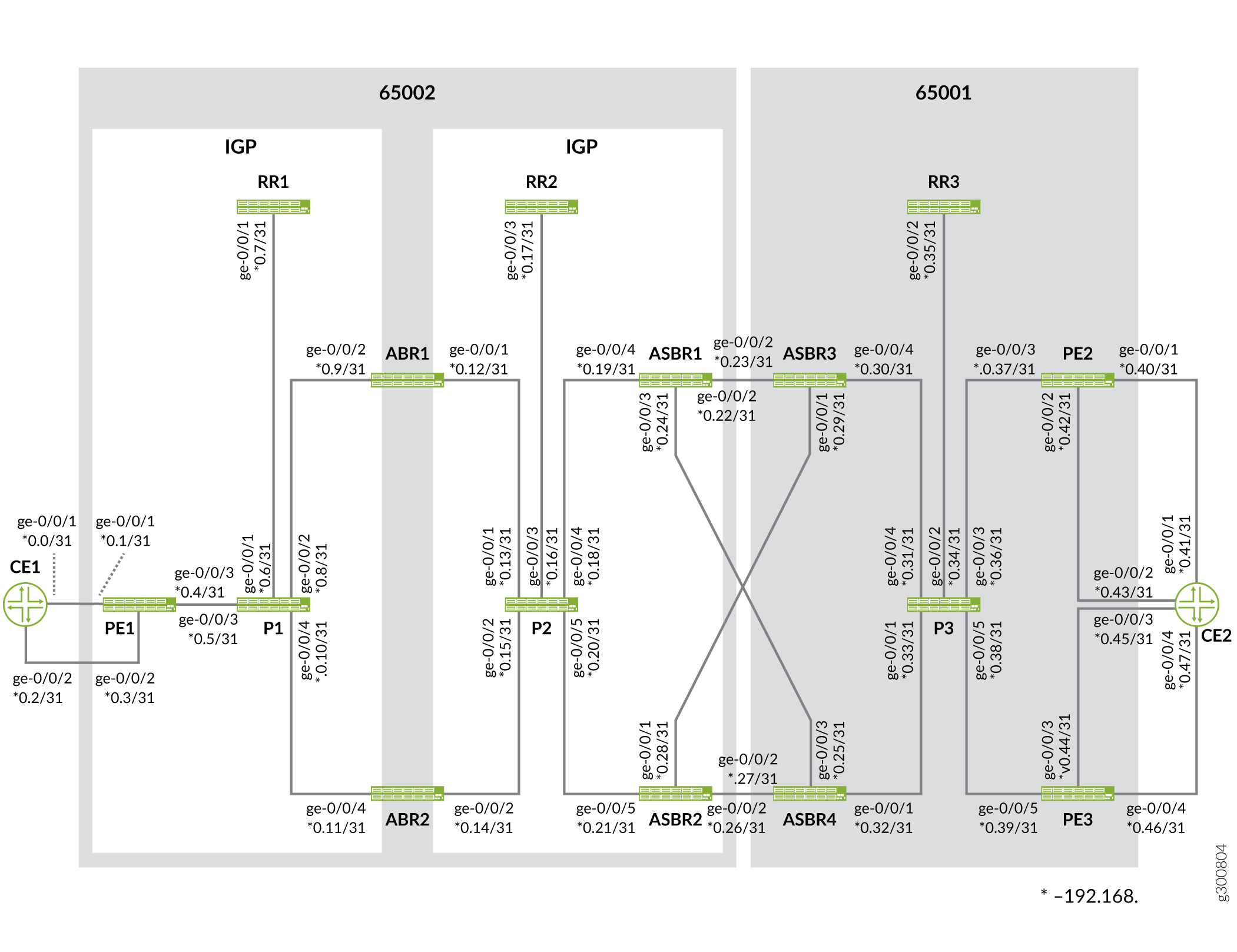
以下の表は、トポロジーで使用されるコンポーネントについて説明しています。
| プライマリーコンポーネント |
デバイスタイプ |
位置 |
|---|---|---|
| CE1 |
MXシリーズ |
カスタマーネットワークに接続されています。 |
| PE1 |
MXシリーズ |
CE1からCE2へのトラフィックを保護してルーティングし直すために、プライマリおよびバックアップルーティングパスで構成されています。 |
| P1-P3 |
MXシリーズ |
トラフィックをトランスポートするためのコアルーター。 |
| ABR1-ABR2 |
MXシリーズ |
エリアボーダールーター |
| ABSR1-ABSR4 |
MXシリーズ |
自律システム境界ルーター |
| RR1-RR3 |
MXシリーズ |
ルートリフレクタ |
| PE2-PE3 |
MXシリーズ |
カスタマーエッジルーター(CE2)に接続されたPEルーター。 |
| CE2 |
MXシリーズ |
カスタマーネットワークに接続されています。 |
PE2とPE3のデバイスアドレスは、ラベル付きユニキャストルートとしてABR1とABR2の両方から学習されます。これらのルートは、IGP/LDPプロトコル上で解決されます。PE1は、PE2とPE3の両方のデバイスからCE2ルートを学習します。
設定
トランスポートプロトコルとしてBGPラベルユニキャストを使用してBGP PICエッジを設定するには、以下のタスクを実行します。
CLIクイックコンフィグレーション
この例をすばやく設定するには、以下のコマンドをコピーしてテキストファイルに貼り付け、改行を削除し、ネットワーク設定に一致させる必要がある詳細情報を変更し、コマンドを [edit] 階層レベルでCLIにコピーアンドペーストして、設定モードから commit を入力します。
デバイスCE1
set interfaces ge-0/0/1 description CE1-to-PE1-Link1 set interfaces ge-0/0/1 vlan-tagging set interfaces ge-0/0/1 unit 0 vlan-id 100 set interfaces ge-0/0/1 unit 0 family inet address 192.168.0.0/31 set interfaces ge-0/0/2 description CE1-to-PE1-Link2 set interfaces ge-0/0/2 vlan-tagging set interfaces ge-0/0/2 unit 0 vlan-id 100 set interfaces ge-0/0/2 unit 0 family inet address 192.168.0.2/31 set interfaces lo0 unit 0 family inet address 10.4.4.4/32 set policy-options policy-statement nhs term 1 from interface lo0.0 set policy-options policy-statement nhs term 1 then next-hop self set policy-options policy-statement nhs term 1 then accept set routing-options router-id 10.4.4.4 set routing-options autonomous-system 65004 set protocols bgp path-selection external-router-id set protocols bgp group toAs2 export nhs set protocols bgp group toAs2 peer-as 65002 set protocols bgp group toAs2 neighbor 192.168.0.1 set protocols bgp group toAs2 neighbor 192.168.0.3
デバイスPE1
set interfaces ge-0/0/1 description PE1-to-CE1-Link1 set interfaces ge-0/0/1 vlan-tagging set interfaces ge-0/0/1 unit 0 vlan-id 100 set interfaces ge-0/0/1 unit 0 family inet address 192.168.0.1/31 set interfaces ge-0/0/2 description PE1-to-CE1-Link2 set interfaces ge-0/0/2 vlan-tagging set interfaces ge-0/0/2 unit 0 vlan-id 100 set interfaces ge-0/0/2 unit 0 family inet address 192.168.0.3/31 set interfaces ge-0/0/3 description PE1-to-P1 set interfaces ge-0/0/3 vlan-tagging set interfaces ge-0/0/3 unit 0 vlan-id 100 set interfaces ge-0/0/3 unit 0 family inet address 192.168.0.4/31 set interfaces ge-0/0/3 unit 0 family iso set interfaces ge-0/0/3 unit 0 family mpls set interfaces lo0 unit 1 family inet address 10.2.2.5/32 set interfaces lo0 unit 1 family iso address 49.0000.0000.aaaa.0005.00 set policy-options policy-statement add-noexport term 1 then community add noexport set policy-options policy-statement allow-lo0 term 1 from interface lo0.1 set policy-options policy-statement allow-lo0 term 1 then accept set policy-options policy-statement allow-lo0 term 2 then reject set policy-options policy-statement export-inet3 term 1 from rib inet.3 set policy-options policy-statement export-inet3 term 1 then accept set policy-options policy-statement export-inet3 term 2 then reject set policy-options policy-statement mp-resolv term 1 from route-filter 10.1.1.0/24 orlonger set policy-options policy-statement mp-resolv term 1 then accept set policy-options policy-statement mp-resolv term 1 then multipath-resolve set policy-options policy-statement mp-resolv term 2 from route-filter 10.2.2.0/24 orlonger set policy-options policy-statement mp-resolv term 2 then accept set policy-options policy-statement mp-resolv term 2 then multipath-resolve set policy-options policy-statement mp-resolv term def then reject set policy-options policy-statement nhs term 1 from protocol bgp set policy-options policy-statement nhs term 1 then local-preference 65200 set policy-options policy-statement nhs term 1 then next-hop self set policy-options policy-statement nhs term 1 then accept set policy-options policy-statement pplb then load-balance per-packet set policy-options policy-statement vrf-export-red term 1 then community add leak2red set policy-options policy-statement vrf-export-red term 1 then accept set policy-options policy-statement vrf-import-red term 1 from community leak2red set policy-options policy-statement vrf-import-red term 1 then accept set policy-options community leak2red members target:100:100 set policy-options community noexport members no-export set policy-options community noexport members no-advertise set routing-instances red routing-options multipath preserve-nexthop-hierarchy set routing-instances red routing-options protect core set routing-instances red protocols bgp group toCE1 peer-as 4 set routing-instances red protocols bgp group toCE1 neighbor 192.168.0.2 set routing-instances red instance-type vrf set routing-instances red interface ge-0/0/2.0 set routing-instances red vrf-import vrf-import-red set routing-instances red vrf-export vrf-export-red set routing-options rib inet.3 protect core set routing-options route-distinguisher-id 10.2.2.5 set routing-options forwarding-table export pplb set routing-options resolution preserve-nexthop-hierarchy set routing-options resolution rib inet.0 import mp-resolv set routing-options interface-routes rib-group inet inet0to3 set routing-options router-id 10.2.2.5 set routing-options autonomous-system 2 set routing-options protect core set routing-options rib-groups inet0to3 import-rib inet.0 set routing-options rib-groups inet0to3 import-rib inet.3 set routing-options rib-groups inet0to3 import-policy allow-lo0 set routing-options rib-groups inet3to0 import-rib inet.3 set routing-options rib-groups inet3to0 import-rib inet.0 set routing-options rib-groups inet3to0 import-policy add-noexport set protocols isis level 1 disable set protocols isis interface ge-0/0/3.0 set protocols isis export allow-lo0 set protocols isis topologies ipv6-unicast set protocols rsvp interface ge-0/0/3.0 set protocols ldp interface ge-0/0/3.0 set protocols mpls label-switched-path toABR1-gold to 10.2.2.3 set protocols mpls label-switched-path toABR1-bronze to 10.2.2.3 set protocols mpls label-switched-path toABR2-gold to 10.2.2.4 set protocols bgp path-selection external-router-id set protocols bgp group toAs2RR type internal set protocols bgp group toAs2RR local-address 10.2.2.5 set protocols bgp group toAs2RR family inet labeled-unicast rib-group inet3to0 set protocols bgp group toAs2RR family inet labeled-unicast add-path receive set protocols bgp group toAs2RR family inet labeled-unicast add-path send path-count 4 set protocols bgp group toAs2RR family inet labeled-unicast nexthop-resolution preserve-nexthop-hierarchy set protocols bgp group toAs2RR family inet labeled-unicast rib inet.3 set protocols bgp group toAs2RR export nhs set protocols bgp group toAs2RR export export-inet3 set protocols bgp group toAs2RR neighbor 10.2.2.6 set protocols bgp group toAs4 peer-as 65004 set protocols bgp group toAs4 neighbor 192.168.0.0 set protocols bgp group toAs1PEs multihop no-nexthop-change set protocols bgp group toAs1PEs local-address 10.2.2.5 set protocols bgp group toAs1PEs family inet unicast set protocols bgp group toAs1PEs family inet-vpn unicast set protocols bgp group toAs1PEs family inet6 unicast set protocols bgp group toAs1PEs family inet6-vpn unicast set protocols bgp group toAs1PEs export nhs set protocols bgp group toAs1PEs peer-as 65001 set protocols bgp group toAs1PEs neighbor 10.1.1.1 set protocols bgp group toAs1PEs neighbor 10.1.1.2 set protocols bgp traceoptions file bgp.log set protocols bgp traceoptions file size 100m set protocols bgp traceoptions flag state detail set protocols bgp traceoptions flag policy set protocols bgp multipath
デバイスP1
set interfaces ge-0/0/1 description P1-to-RR1 set interfaces ge-0/0/1 vlan-tagging set interfaces ge-0/0/1 unit 0 vlan-id 100 set interfaces ge-0/0/1 unit 0 family inet address 192.168.0.6/31 set interfaces ge-0/0/1 unit 0 family iso set interfaces ge-0/0/1 unit 0 family mpls set interfaces ge-0/0/2 description P1-to-ABR1 set interfaces ge-0/0/2 vlan-tagging set interfaces ge-0/0/2 unit 0 vlan-id 100 set interfaces ge-0/0/2 unit 0 family inet address 192.168.0.8/31 set interfaces ge-0/0/2 unit 0 family iso set interfaces ge-0/0/2 unit 0 family mpls set interfaces ge-0/0/3 description P1-to-PE1 set interfaces ge-0/0/3 vlan-tagging set interfaces ge-0/0/3 unit 0 vlan-id 100 set interfaces ge-0/0/3 unit 0 family inet address 192.168.0.5/31 set interfaces ge-0/0/3 unit 0 family iso set interfaces ge-0/0/3 unit 0 family mpls set interfaces ge-0/0/4 description P1-to-ABR2 set interfaces ge-0/0/4 vlan-tagging set interfaces ge-0/0/4 unit 0 vlan-id 100 set interfaces ge-0/0/4 unit 0 family inet address 192.168.0.10/31 set interfaces ge-0/0/4 unit 0 family iso set interfaces ge-0/0/4 unit 0 family mpls set interfaces lo0 unit 0 family inet address 10.2.2.8/32 set interfaces lo0 unit 0 family iso address 49.0000.0000.aaaa.0008.00 set policy-options policy-statement allow-lo0 term 1 from interface lo0.0 set policy-options policy-statement allow-lo0 term 1 then accept set policy-options policy-statement allow-lo0 term 2 then reject set routing-options router-id 10.2.2.8 set protocols isis level 1 disable set protocols isis interface all set protocols isis export allow-lo0 set protocols isis topologies ipv6-unicast set protocols rsvp interface all set protocols ldp interface all set protocols mpls interface all
デバイスRR1
set interfaces ge-0/0/1 description RR1-to-P1 set interfaces ge-0/0/1 vlan-tagging set interfaces ge-0/0/1 unit 0 vlan-id 100 set interfaces ge-0/0/1 unit 0 family inet address 192.168.0.7/31 set interfaces ge-0/0/1 unit 0 family iso set interfaces ge-0/0/1 unit 0 family mpls set interfaces lo0 unit 1 family inet address 10.2.2.6/32 set interfaces lo0 unit 1 family iso address 49.0000.0000.aaaa.0006.00 set policy-options policy-statement add-noexport term 1 then community add noexport set policy-options policy-statement allow-lo0 term 1 from interface lo0.1 set policy-options policy-statement allow-lo0 term 1 then accept set policy-options policy-statement allow-lo0 term 2 then reject set policy-options policy-statement export-inet3 term 1 from rib inet.3 set policy-options policy-statement export-inet3 term 1 then accept set policy-options policy-statement export-inet3 term 2 then reject set policy-options policy-statement pplb then load-balance per-packet set policy-options community noexport members no-export set policy-options community noexport members no-advertise set routing-options forwarding-table export pplb set routing-options interface-routes rib-group inet inet0to3 set routing-options router-id 10.2.2.6 set routing-options autonomous-system 2 set routing-options rib-groups inet0to3 import-rib inet.0 set routing-options rib-groups inet0to3 import-rib inet.3 set routing-options rib-groups inet0to3 import-policy allow-lo0 set routing-options rib-groups inet3to0 import-rib inet.3 set routing-options rib-groups inet3to0 import-rib inet.0 set routing-options rib-groups inet3to0 import-rib inet6.3 set routing-options rib-groups inet3to0 import-policy add-noexport set protocols isis level 1 disable set protocols isis interface all set protocols isis export allow-lo0 set protocols isis topologies ipv6-unicast set protocols rsvp interface all set protocols ldp interface all set protocols mpls interface all set protocols bgp path-selection external-router-id set protocols bgp group toAs2Reg2BNs type internal set protocols bgp group toAs2Reg2BNs family inet labeled-unicast rib-group inet3to0 set protocols bgp group toAs2Reg2BNs family inet labeled-unicast add-path receive set protocols bgp group toAs2Reg2BNs family inet labeled-unicast add-path send path-count 4 set protocols bgp group toAs2Reg2BNs family inet labeled-unicast rib inet.3 set protocols bgp group toAs2Reg2BNs export export-inet3 set protocols bgp group toAs2Reg2BNs neighbor 10.2.2.3 set protocols bgp group toAs2Reg2BNs neighbor 10.2.2.4 set protocols bgp group toAs2Reg2BNs neighbor 10.2.2.5 set protocols bgp traceoptions file bgp.log set protocols bgp traceoptions file size 100m set protocols bgp traceoptions flag state detail set protocols bgp traceoptions flag policy set protocols bgp local-address 10.2.2.6 set protocols bgp cluster 10.2.2.6
デバイスABR1
set interfaces ge-0/0/1 description ABR1-to-P2 set interfaces ge-0/0/1 vlan-tagging set interfaces ge-0/0/1 unit 0 vlan-id 100 set interfaces ge-0/0/1 unit 0 family inet address 192.168.0.12/31 set interfaces ge-0/0/1 unit 0 family iso set interfaces ge-0/0/1 unit 0 family mpls set interfaces ge-0/0/2 description ABR1-to-P1 set interfaces ge-0/0/2 vlan-tagging set interfaces ge-0/0/2 unit 0 vlan-id 100 set interfaces ge-0/0/2 unit 0 family inet address 192.168.0.9/31 set interfaces ge-0/0/2 unit 0 family iso set interfaces ge-0/0/2 unit 0 family mpls set interfaces lo0 unit 0 family inet address 10.2.2.3/32 set interfaces lo0 unit 0 family iso address 49.0000.0000.aaaa.0003.00 set policy-options policy-statement allow-lo0 term 1 from interface lo0.0 set policy-options policy-statement allow-lo0 term 1 then accept set policy-options policy-statement allow-lo0 term 2 then reject set policy-options policy-statement nhs term 1 from protocol bgp set policy-options policy-statement nhs term 1 then next-hop self set policy-options policy-statement nhs term 1 then accept set policy-options policy-statement pplb then load-balance per-packet set routing-options forwarding-table export pplb set routing-options router-id 10.2.2.3 set routing-options autonomous-system 65002 set protocols isis level 1 disable set protocols isis interface all set protocols isis export allow-lo0 set protocols isis topologies ipv6-unicast set protocols rsvp interface all set protocols ldp interface all set protocols mpls label-switched-path toASBR2-gold to 10.2.2.2 set protocols mpls label-switched-path toASBR1-bronze to 10.2.2.1 set protocols mpls label-switched-path toASBR2-bronze to 10.2.2.2 set protocols mpls interface all set protocols bgp group toAs2RR type internal set protocols bgp group toAs2RR local-address 10.2.2.3 set protocols bgp group toAs2RR advertise-inactive set protocols bgp group toAs2RR family inet labeled-unicast add-path receive set protocols bgp group toAs2RR family inet labeled-unicast add-path send path-count 4 set protocols bgp group toAs2RR family inet labeled-unicast rib inet.3 set protocols bgp group toAs2RR export nhs set protocols bgp group toAs2RR cluster 10.2.2.3 set protocols bgp group toAs2RR neighbor 10.2.2.6 set protocols bgp group toAs2RR neighbor 10.2.2.7 set protocols bgp traceoptions file bgp.log set protocols bgp traceoptions file size 100m set protocols bgp traceoptions flag state detail set protocols bgp traceoptions flag policy
デバイスABR2
set interfaces ge-0/0/2 description ABR2-to-P2 set interfaces ge-0/0/2 vlan-tagging set interfaces ge-0/0/2 unit 0 vlan-id 100 set interfaces ge-0/0/2 unit 0 family inet address 192.168.0.14/31 set interfaces ge-0/0/2 unit 0 family iso set interfaces ge-0/0/2 unit 0 family mpls set interfaces ge-0/0/4 description ABR2-to-P1 set interfaces ge-0/0/4 vlan-tagging set interfaces ge-0/0/4 unit 0 vlan-id 100 set interfaces ge-0/0/4 unit 0 family inet address 192.168.0.11/31 set interfaces ge-0/0/4 unit 0 family iso set interfaces ge-0/0/4 unit 0 family mpls set interfaces lo0 unit 0 family inet address 10.2.2.4/32 set interfaces lo0 unit 0 family iso address 49.0000.0000.aaaa.0004.00 set policy-options policy-statement allow-lo0 term 1 from interface lo0.0 set policy-options policy-statement allow-lo0 term 1 then accept set policy-options policy-statement allow-lo0 term 2 then reject set policy-options policy-statement nhs term 1 from protocol bgp set policy-options policy-statement nhs term 1 then next-hop self set policy-options policy-statement nhs term 1 then accept set policy-options policy-statement pplb then load-balance per-packet set routing-options forwarding-table export pplb set routing-options router-id 10.2.2.4 set routing-options autonomous-system 65002 set protocols isis level 1 disable set protocols isis interface all set protocols isis export allow-lo0 set protocols isis topologies ipv6-unicast set protocols rsvp interface all set protocols ldp interface all set protocols mpls label-switched-path toASBR1-bronze to 10.2.2.1 set protocols mpls interface all set protocols bgp group toAs2RR type internal set protocols bgp group toAs2RR local-address 10.2.2.4 set protocols bgp group toAs2RR advertise-inactive set protocols bgp group toAs2RR family inet labeled-unicast add-path receive set protocols bgp group toAs2RR family inet labeled-unicast add-path send path-count 4 set protocols bgp group toAs2RR family inet labeled-unicast rib inet.3 set protocols bgp group toAs2RR export nhs set protocols bgp group toAs2RR cluster 10.2.2.4 set protocols bgp group toAs2RR neighbor 10.2.2.6 set protocols bgp group toAs2RR neighbor 10.2.2.7 set protocols bgp traceoptions file bgp.log set protocols bgp traceoptions file size 100m set protocols bgp traceoptions flag state detail set protocols bgp traceoptions flag policy
デバイスP2
set interfaces ge-0/0/1 description P2-to-ABR1 set interfaces ge-0/0/1 vlan-tagging set interfaces ge-0/0/1 unit 0 vlan-id 100 set interfaces ge-0/0/1 unit 0 family inet address 192.168.0.13/31 set interfaces ge-0/0/1 unit 0 family iso set interfaces ge-0/0/1 unit 0 family mpls set interfaces ge-0/0/2 description P2-to-ABR2 set interfaces ge-0/0/2 vlan-tagging set interfaces ge-0/0/2 unit 0 vlan-id 100 set interfaces ge-0/0/2 unit 0 family inet address 192.168.0.15/31 set interfaces ge-0/0/2 unit 0 family iso set interfaces ge-0/0/2 unit 0 family mpls set interfaces ge-0/0/3 description P2-to-RR2 set interfaces ge-0/0/3 vlan-tagging set interfaces ge-0/0/3 unit 0 vlan-id 100 set interfaces ge-0/0/3 unit 0 family inet address 192.168.0.16/31 set interfaces ge-0/0/3 unit 0 family iso set interfaces ge-0/0/3 unit 0 family mpls set interfaces ge-0/0/4 description P2-to-ASBR1 set interfaces ge-0/0/4 vlan-tagging set interfaces ge-0/0/4 unit 0 vlan-id 100 set interfaces ge-0/0/4 unit 0 family inet address 192.168.0.18/31 set interfaces ge-0/0/4 unit 0 family iso set interfaces ge-0/0/4 unit 0 family mpls set interfaces ge-0/0/5 description P2-to-ASBR2 set interfaces ge-0/0/5 vlan-tagging set interfaces ge-0/0/5 unit 0 vlan-id 100 set interfaces ge-0/0/5 unit 0 family inet address 192.168.0.20/31 set interfaces ge-0/0/5 unit 0 family iso set interfaces ge-0/0/5 unit 0 family mpls set interfaces lo0 unit 0 family inet address 10.2.2.9/32 set interfaces lo0 unit 0 family iso address 49.0000.0000.aaaa.0009.00 set policy-options policy-statement allow-lo0 term 1 from interface lo0.0 set policy-options policy-statement allow-lo0 term 1 then accept set policy-options policy-statement allow-lo0 term 2 then reject set routing-options router-id 10.2.2.9 set protocols isis level 1 disable set protocols isis interface all set protocols isis export allow-lo0 set protocols isis topologies ipv6-unicast set protocols rsvp interface all set protocols ldp interface all set protocols mpls interface all
デバイスRR2
set interfaces ge-0/0/3 description RR2-to-P2 set interfaces ge-0/0/3 vlan-tagging set interfaces ge-0/0/3 unit 0 vlan-id 100 set interfaces ge-0/0/3 unit 0 family inet address 192.168.0.17/31 set interfaces ge-0/0/3 unit 0 family iso set interfaces ge-0/0/3 unit 0 family mpls set interfaces lo0 unit 1 family inet address 10.2.2.7/32 set interfaces lo0 unit 1 family iso address 49.0000.0000.aaaa.0007.00 set policy-options policy-statement allow-lo0 term 1 from interface lo0.1 set policy-options policy-statement allow-lo0 term 1 then accept set policy-options policy-statement allow-lo0 term 2 then reject set policy-options policy-statement export-inet3 term 1 from rib inet.3 set policy-options policy-statement export-inet3 term 1 then accept set policy-options policy-statement export-inet3 term 2 then reject set policy-options policy-statement pplb then load-balance per-packet set routing-options forwarding-table export pplb set routing-options interface-routes rib-group inet inet0to3 set routing-options router-id 10.2.2.7 set routing-options autonomous-system 65002 set routing-options rib-groups inet0to3 import-rib inet.0 set routing-options rib-groups inet0to3 import-rib inet.3 set routing-options rib-groups inet0to3 import-policy allow-lo0 set protocols isis level 1 disable set protocols isis interface all set protocols isis export allow-lo0 set protocols isis topologies ipv6-unicast set protocols rsvp interface all set protocols ldp interface all set protocols mpls interface all set protocols bgp path-selection external-router-id set protocols bgp group toAs2Reg1BNs type internal set protocols bgp group toAs2Reg1BNs family inet labeled-unicast add-path receive set protocols bgp group toAs2Reg1BNs family inet labeled-unicast add-path send path-count 4 set protocols bgp group toAs2Reg1BNs family inet labeled-unicast rib inet.3 set protocols bgp group toAs2Reg1BNs neighbor 10.2.2.1 set protocols bgp group toAs2Reg1BNs neighbor 10.2.2.2 set protocols bgp group toAs2Reg1BNs neighbor 10.2.2.3 set protocols bgp group toAs2Reg1BNs neighbor 10.2.2.4 set protocols bgp traceoptions file bgp.log set protocols bgp traceoptions file size 100m set protocols bgp traceoptions flag state detail set protocols bgp traceoptions flag policy set protocols bgp local-address 10.2.2.7 set protocols bgp cluster 10.2.2.7
デバイスASBR1
set interfaces ge-0/0/2 description ASBR1-to-ASBR3 set interfaces ge-0/0/2 vlan-tagging set interfaces ge-0/0/2 unit 0 vlan-id 100 set interfaces ge-0/0/2 unit 0 family inet address 192.168.0.22/31 set interfaces ge-0/0/2 unit 0 family mpls set interfaces ge-0/0/3 description ASBR1-to-ASBR4 set interfaces ge-0/0/3 vlan-tagging set interfaces ge-0/0/3 unit 0 vlan-id 100 set interfaces ge-0/0/3 unit 0 family inet address 192.168.0.24/31 set interfaces ge-0/0/3 unit 0 family mpls set interfaces ge-0/0/4 description ASBR1-to-P2 set interfaces ge-0/0/4 vlan-tagging set interfaces ge-0/0/4 unit 0 vlan-id 100 set interfaces ge-0/0/4 unit 0 family inet address 192.168.0.19/31 set interfaces ge-0/0/4 unit 0 family iso set interfaces ge-0/0/4 unit 0 family mpls set interfaces lo0 unit 0 family inet address 10.2.2.1/32 set interfaces lo0 unit 0 family iso address 49.0000.0000.aaaa.0001.00 set policy-options policy-statement allow-lo0 term 1 from interface lo0.0 set policy-options policy-statement allow-lo0 term 1 then accept set policy-options policy-statement allow-lo0 term 2 then reject set policy-options policy-statement nhs term 1 from protocol bgp set policy-options policy-statement nhs term 1 then next-hop self set policy-options policy-statement nhs term 1 then accept set policy-options policy-statement pplb then load-balance per-packet set routing-options forwarding-table export pplb set routing-options router-id 10.2.2.1 set routing-options autonomous-system 65002 set protocols isis level 1 disable set protocols isis interface ge-0/0/4.0 set protocols isis export allow-lo0 set protocols isis topologies ipv6-unicast set protocols rsvp interface ge-0/0/4.0 set protocols ldp interface ge-0/0/4.0 set protocols mpls interface ge-0/0/4.0 set protocols bgp path-selection external-router-id set protocols bgp group toAs1-T family inet labeled-unicast rib inet.3 set protocols bgp group toAs1-T peer-as 1 set protocols bgp group toAs1-T neighbor 192.168.0.23 set protocols bgp group toAs1-T neighbor 192.168.0.27 set protocols bgp group toAs2RR type internal set protocols bgp group toAs2RR local-address 10.2.2.1 set protocols bgp group toAs2RR advertise-external set protocols bgp group toAs2RR family inet labeled-unicast rib inet.3 set protocols bgp group toAs2RR export nhs set protocols bgp group toAs2RR neighbor 10.2.2.7 set protocols bgp traceoptions file bgp.log set protocols bgp traceoptions file size 100m set protocols bgp traceoptions flag state detail set protocols bgp traceoptions flag policy
デバイスASBR2
set interfaces ge-0/0/1 description ASBR2-to-ASBR3 set interfaces ge-0/0/1 vlan-tagging set interfaces ge-0/0/1 unit 0 vlan-id 100 set interfaces ge-0/0/1 unit 0 family inet address 192.168.0.28/31 set interfaces ge-0/0/1 unit 0 family mpls set interfaces ge-0/0/2 description ASBR2-to-ASBR4 set interfaces ge-0/0/2 vlan-tagging set interfaces ge-0/0/2 unit 0 vlan-id 100 set interfaces ge-0/0/2 unit 0 family inet address 192.168.0.26/31 set interfaces ge-0/0/2 unit 0 family mpls set interfaces ge-0/0/5 description ASBR2-to-P2 set interfaces ge-0/0/5 vlan-tagging set interfaces ge-0/0/5 unit 0 vlan-id 100 set interfaces ge-0/0/5 unit 0 family inet address 192.168.0.21/31 set interfaces ge-0/0/5 unit 0 family iso set interfaces ge-0/0/5 unit 0 family mpls set interfaces lo0 unit 0 family inet address 10.2.2.2/32 set interfaces lo0 unit 0 family iso address 49.0000.0000.aaaa.0002.00 set policy-options policy-statement allow-lo0 term 1 from interface lo0.0 set policy-options policy-statement allow-lo0 term 1 then accept set policy-options policy-statement allow-lo0 term 2 then reject set policy-options policy-statement nhs term 1 from protocol bgp set policy-options policy-statement nhs term 1 then next-hop self set policy-options policy-statement nhs term 1 then accept set policy-options policy-statement pplb then load-balance per-packet set routing-options forwarding-table export pplb set routing-options router-id 10.2.2.2 set routing-options autonomous-system 65002 set protocols isis level 1 disable set protocols isis interface ge-0/0/5.0 set protocols isis export allow-lo0 set protocols isis topologies ipv6-unicast set protocols rsvp interface ge-0/0/5.0 set protocols ldp interface ge-0/0/5.0 set protocols mpls interface ge-0/0/5.0 set protocols bgp path-selection external-router-id set protocols bgp group toAs1-T family inet labeled-unicast rib inet.3 set protocols bgp group toAs1-T peer-as 1 set protocols bgp group toAs1-T neighbor 192.168.0.29 set protocols bgp group toAs1-T neighbor 192.168.0.25 set protocols bgp group toAs2RR type internal set protocols bgp group toAs2RR local-address 10.2.2.2 set protocols bgp group toAs2RR advertise-external set protocols bgp group toAs2RR family inet labeled-unicast rib inet.3 set protocols bgp group toAs2RR export nhs set protocols bgp group toAs2RR neighbor 10.2.2.7 set protocols bgp traceoptions file bgp.log set protocols bgp traceoptions file size 100m set protocols bgp traceoptions flag state detail set protocols bgp traceoptions flag policy
デバイスASBR3
set interfaces ge-0/0/1 description ASBR3-to-ASBR2 set interfaces ge-0/0/1 vlan-tagging set interfaces ge-0/0/1 unit 0 vlan-id 100 set interfaces ge-0/0/1 unit 0 family inet address 192.168.0.29/31 set interfaces ge-0/0/1 unit 0 family mpls set interfaces ge-0/0/2 description ASBR3-to-ASBR1 set interfaces ge-0/0/2 vlan-tagging set interfaces ge-0/0/2 unit 0 vlan-id 100 set interfaces ge-0/0/2 unit 0 family inet address 192.168.0.23/31 set interfaces ge-0/0/2 unit 0 family mpls set interfaces ge-0/0/4 description ASBR3-to-P3 set interfaces ge-0/0/4 vlan-tagging set interfaces ge-0/0/4 unit 0 vlan-id 100 set interfaces ge-0/0/4 unit 0 family inet address 192.168.0.30/31 set interfaces ge-0/0/4 unit 0 family iso set interfaces ge-0/0/4 unit 0 family mpls set interfaces lo0 unit 0 family inet address 10.1.1.3/32 set interfaces lo0 unit 0 family iso address 49.0000.0000.aaaa.0003.00 set policy-options policy-statement allow-lo0 term 1 from interface lo0.0 set policy-options policy-statement allow-lo0 term 1 then accept set policy-options policy-statement allow-lo0 term 2 then reject set policy-options policy-statement nhs term 1 from protocol bgp set policy-options policy-statement nhs term 1 then next-hop self set policy-options policy-statement nhs term 1 then accept set policy-options policy-statement pplb then load-balance per-packet set routing-options forwarding-table export pplb set routing-options router-id 10.1.1.3 set routing-options autonomous-system 65001 set protocols isis level 1 disable set protocols isis interface ge-0/0/4.0 set protocols isis export allow-lo0 set protocols isis topologies ipv6-unicast set protocols rsvp interface ge-0/0/4.0 set protocols ldp interface ge-0/0/4.0 set protocols mpls label-switched-path toPE2-gold to 10.1.1.1 set protocols mpls interface ge-0/0/4.0 set protocols bgp path-selection external-router-id set protocols bgp group toAs2-T family inet labeled-unicast rib inet.3 set protocols bgp group toAs2-T peer-as 65002 set protocols bgp group toAs2-T neighbor 192.168.0.22 set protocols bgp group toAs2-T neighbor 192.168.0.28 set protocols bgp group toAs1RR type internal set protocols bgp group toAs1RR local-address 10.1.1.3 set protocols bgp group toAs1RR advertise-external set protocols bgp group toAs1RR family inet labeled-unicast rib inet.3 set protocols bgp group toAs1RR export nhs set protocols bgp group toAs1RR neighbor 10.1.1.6 set protocols bgp traceoptions file bgp.log set protocols bgp traceoptions file size 100m set protocols bgp traceoptions flag state detail set protocols bgp traceoptions flag policy
デバイスASBR4
set interfaces ge-0/0/1 description ASBR4-to-P3 set interfaces ge-0/0/1 vlan-tagging set interfaces ge-0/0/1 unit 0 vlan-id 100 set interfaces ge-0/0/1 unit 0 family inet address 192.168.0.32/31 set interfaces ge-0/0/1 unit 0 family iso set interfaces ge-0/0/1 unit 0 family mpls set interfaces ge-0/0/2 description ASBR4-to-ASBR2 set interfaces ge-0/0/2 vlan-tagging set interfaces ge-0/0/2 unit 0 vlan-id 100 set interfaces ge-0/0/2 unit 0 family inet address 192.168.0.27/31 set interfaces ge-0/0/2 unit 0 family mpls set interfaces ge-0/0/3 description ASBR4-to-ASBR1 set interfaces ge-0/0/3 vlan-tagging set interfaces ge-0/0/3 unit 0 vlan-id 100 set interfaces ge-0/0/3 unit 0 family inet address 192.168.0.25/31 set interfaces ge-0/0/3 unit 0 family mpls set interfaces lo0 unit 0 family inet address 10.1.1.4/32 set interfaces lo0 unit 0 family iso address 49.0000.0000.aaaa.0004.00 set policy-options policy-statement allow-lo0 term 1 from interface lo0.0 set policy-options policy-statement allow-lo0 term 1 then accept set policy-options policy-statement allow-lo0 term 2 then reject set policy-options policy-statement nhs term 1 from protocol bgp set policy-options policy-statement nhs term 1 then next-hop self set policy-options policy-statement nhs term 1 then accept set policy-options policy-statement pplb then load-balance per-packet set routing-options forwarding-table export pplb set routing-options router-id 10.1.1.4 set routing-options autonomous-system 65001 set protocols isis level 1 disable set protocols isis interface ge-0/0/1.0 set protocols isis export allow-lo0 set protocols isis topologies ipv6-unicast set protocols rsvp interface ge-0/0/1.0 set protocols ldp interface ge-0/0/1.0 set protocols mpls label-switched-path toPE2-bronze to 10.1.1.1 set protocols mpls label-switched-path toPE3-bronze to 10.1.1.2 set protocols mpls interface ge-0/0/1.0 set protocols bgp path-selection external-router-id set protocols bgp group toAs2-T family inet labeled-unicast rib inet.3 set protocols bgp group toAs2-T peer-as 2 set protocols bgp group toAs2-T neighbor 192.168.0.26 set protocols bgp group toAs2-T neighbor 192.168.0.24 set protocols bgp group toAs1RR type internal set protocols bgp group toAs1RR local-address 10.1.1.4 set protocols bgp group toAs1RR advertise-external set protocols bgp group toAs1RR family inet labeled-unicast rib inet.3 set protocols bgp group toAs1RR export nhs set protocols bgp group toAs1RR neighbor 10.1.1.6 set protocols bgp traceoptions file bgp.log set protocols bgp traceoptions file size 100m set protocols bgp traceoptions flag state detail set protocols bgp traceoptions flag policy
デバイスRR3
set interfaces ge-0/0/2 description RR3-to-P3 set interfaces ge-0/0/2 vlan-tagging set interfaces ge-0/0/2 unit 0 vlan-id 100 set interfaces ge-0/0/2 unit 0 family inet address 192.168.0.35/31 set interfaces ge-0/0/2 unit 0 family iso set interfaces ge-0/0/2 unit 0 family mpls set interfaces lo0 unit 1 family inet address 10.1.1.6/32 set interfaces lo0 unit 1 family iso address 49.0000.0000.aaaa.0006.00 set policy-options policy-statement add-noexport term 1 then community add noexport set policy-options policy-statement allow-lo0 term 1 from interface lo0.1 set policy-options policy-statement allow-lo0 term 1 then accept set policy-options policy-statement allow-lo0 term 2 then reject set policy-options policy-statement export-inet3 term 1 from rib inet.3 set policy-options policy-statement export-inet3 term 1 then accept set policy-options policy-statement export-inet3 term 2 then reject set policy-options policy-statement pplb then load-balance per-packet set policy-options community noexport members no-export set policy-options community noexport members no-advertise set routing-options forwarding-table export pplb set routing-options interface-routes rib-group inet inet0to3 set routing-options router-id 10.1.1.6 set routing-options autonomous-system 1 set routing-options rib-groups inet0to3 import-rib inet.0 set routing-options rib-groups inet0to3 import-rib inet.3 set routing-options rib-groups inet0to3 import-policy allow-lo0 set routing-options rib-groups inet3to0 import-rib inet.3 set routing-options rib-groups inet3to0 import-rib inet.0 set routing-options rib-groups inet3to0 import-policy add-noexport set protocols isis level 1 disable set protocols isis interface all set protocols isis export allow-lo0 set protocols isis topologies ipv6-unicast set protocols rsvp interface all set protocols ldp interface all set protocols mpls interface all set protocols bgp path-selection external-router-id set protocols bgp group toAs1BNs type internal set protocols bgp group toAs1BNs family inet labeled-unicast rib-group inet3to0 set protocols bgp group toAs1BNs family inet labeled-unicast add-path receive set protocols bgp group toAs1BNs family inet labeled-unicast add-path send path-count 4 set protocols bgp group toAs1BNs family inet labeled-unicast rib inet.3 set protocols bgp group toAs1BNs export export-inet3 set protocols bgp group toAs1BNs neighbor 10.1.1.3 set protocols bgp group toAs1BNs neighbor 10.1.1.4 set protocols bgp group toAs1BNs neighbor 10.1.1.2 set protocols bgp group toAs1BNs neighbor 10.1.1.1 set protocols bgp traceoptions file bgp.log set protocols bgp traceoptions file size 100m set protocols bgp traceoptions flag state detail set protocols bgp traceoptions flag policy set protocols bgp local-address 10.1.1.6 set protocols bgp cluster 10.1.1.6
デバイスP3
set interfaces ge-0/0/1 description P3-to-ASBR4 set interfaces ge-0/0/1 vlan-tagging set interfaces ge-0/0/1 unit 0 vlan-id 100 set interfaces ge-0/0/1 unit 0 family inet address 192.168.0.33/31 set interfaces ge-0/0/1 unit 0 family iso set interfaces ge-0/0/1 unit 0 family mpls set interfaces ge-0/0/2 description P3-to-RR3 set interfaces ge-0/0/2 vlan-tagging set interfaces ge-0/0/2 unit 0 vlan-id 100 set interfaces ge-0/0/2 unit 0 family inet address 192.168.0.34/31 set interfaces ge-0/0/2 unit 0 family iso set interfaces ge-0/0/2 unit 0 family mpls set interfaces ge-0/0/3 description P3-to-PE2 set interfaces ge-0/0/3 vlan-tagging set interfaces ge-0/0/3 unit 0 vlan-id 100 set interfaces ge-0/0/3 unit 0 family inet address 192.168.0.36/31 set interfaces ge-0/0/3 unit 0 family iso set interfaces ge-0/0/3 unit 0 family mpls set interfaces ge-0/0/4 description P3-to-ASBR3 set interfaces ge-0/0/4 vlan-tagging set interfaces ge-0/0/4 unit 0 vlan-id 100 set interfaces ge-0/0/4 unit 0 family inet address 192.168.0.31/31 set interfaces ge-0/0/4 unit 0 family iso set interfaces ge-0/0/4 unit 0 family mpls set interfaces ge-0/0/5 description P3-to-PE3 set interfaces ge-0/0/5 vlan-tagging set interfaces ge-0/0/5 unit 0 vlan-id 100 set interfaces ge-0/0/5 unit 0 family inet address 192.168.0.38/31 set interfaces ge-0/0/5 unit 0 family iso set interfaces ge-0/0/5 unit 0 family mpls set interfaces lo0 unit 0 family inet address 10.1.1.5/32 set interfaces lo0 unit 0 family iso address 49.0000.0000.aaaa.0005.00 set policy-options policy-statement allow-lo0 term 1 from interface lo0.0 set policy-options policy-statement allow-lo0 term 1 then accept set policy-options policy-statement allow-lo0 term 2 then reject set routing-options router-id 10.1.1.5 set protocols isis level 1 disable set protocols isis interface all set protocols isis export allow-lo0 set protocols isis topologies ipv6-unicast set protocols rsvp interface all set protocols ldp interface all set protocols mpls interface all
デバイスPE2
set interfaces ge-0/0/1 description PE2-to-CE2-Link1 set interfaces ge-0/0/1 vlan-tagging set interfaces ge-0/0/1 unit 0 vlan-id 100 set interfaces ge-0/0/1 unit 0 family inet address 192.168.0.40/31 set interfaces ge-0/0/2 description PE2-to-CE2-Link2 set interfaces ge-0/0/2 vlan-tagging set interfaces ge-0/0/2 unit 0 vlan-id 100 set interfaces ge-0/0/2 unit 0 family inet address 192.168.0.42/31 set interfaces ge-0/0/3 description PE2-to-P3 set interfaces ge-0/0/3 vlan-tagging set interfaces ge-0/0/3 unit 0 vlan-id 100 set interfaces ge-0/0/3 unit 0 family inet address 192.168.0.37/31 set interfaces ge-0/0/3 unit 0 family iso set interfaces ge-0/0/3 unit 0 family mpls set interfaces lo0 unit 1 family inet address 10.1.1.1/32 set interfaces lo0 unit 1 family iso address 49.0000.0000.aaaa.0001.00 set policy-options policy-statement add-noexport term 1 then community add noexport set policy-options policy-statement allow-lo0 term 1 from interface lo0.1 set policy-options policy-statement allow-lo0 term 1 then accept set policy-options policy-statement allow-lo0 term 2 then reject set policy-options policy-statement export-inet3 term 1 from rib inet.3 set policy-options policy-statement export-inet3 term 1 then accept set policy-options policy-statement export-inet3 term 2 then reject set policy-options policy-statement nhs term 1 from protocol bgp set policy-options policy-statement nhs term 1 then metric add 0 set policy-options policy-statement nhs term 1 then local-preference 200 set policy-options policy-statement nhs term 1 then next-hop self set policy-options policy-statement nhs term 1 then accept set policy-options policy-statement pplb then load-balance per-packet set policy-options policy-statement vrf-export-red term 1 then community add leak2red set policy-options policy-statement vrf-export-red term 1 then accept set policy-options policy-statement vrf-import-red term 1 from community leak2red set policy-options policy-statement vrf-import-red term 1 then accept set policy-options community leak2red members target:100:100 set policy-options community noexport members no-export set policy-options community noexport members no-advertise set routing-instances red protocols bgp group toCE2 peer-as 65003 set routing-instances red protocols bgp group toCE2 neighbor 192.168.0.43 set routing-instances red instance-type vrf set routing-instances red interface ge-0/0/2.0 set routing-instances red vrf-import vrf-import-red set routing-instances red vrf-export vrf-export-red set routing-options route-distinguisher-id 10.1.1.1 set routing-options forwarding-table export pplb set routing-options interface-routes rib-group inet inet0to3 set routing-options router-id 10.1.1.1 set routing-options autonomous-system 1 set routing-options rib-groups inet0to3 import-rib inet.0 set routing-options rib-groups inet0to3 import-rib inet.3 set routing-options rib-groups inet0to3 import-policy allow-lo0 set routing-options rib-groups inet3to0 import-rib inet.3 set routing-options rib-groups inet3to0 import-rib inet.0 set routing-options rib-groups inet3to0 import-policy add-noexport set protocols isis level 1 disable set protocols isis interface ge-0/0/3.0 set protocols isis export allow-lo0 set protocols isis topologies ipv6-unicast set protocols rsvp interface ge-0/0/3.0 set protocols ldp interface ge-0/0/3.0 set protocols mpls interface ge-0/0/3.0 set protocols bgp path-selection external-router-id set protocols bgp group toAs3-1 peer-as 65003 set protocols bgp group toAs3-1 neighbor 192.168.0.41 set protocols bgp group toAs1RR type internal set protocols bgp group toAs1RR local-address 10.1.1.1 set protocols bgp group toAs1RR advertise-external set protocols bgp group toAs1RR family inet labeled-unicast rib-group inet3to0 set protocols bgp group toAs1RR family inet labeled-unicast add-path receive set protocols bgp group toAs1RR family inet labeled-unicast add-path send path-count 4 set protocols bgp group toAs1RR family inet labeled-unicast rib inet.3 set protocols bgp group toAs1RR family inet6-vpn unicast set protocols bgp group toAs1RR export nhs set protocols bgp group toAs1RR export export-inet3 set protocols bgp group toAs1RR neighbor 10.1.1.6 set protocols bgp group toAs2PEs multihop no-nexthop-change set protocols bgp group toAs2PEs local-address 10.1.1.1 set protocols bgp group toAs2PEs family inet unicast set protocols bgp group toAs2PEs family inet-vpn unicast set protocols bgp group toAs2PEs family inet6 unicast set protocols bgp group toAs2PEs family inet6-vpn unicast set protocols bgp group toAs2PEs export nhs set protocols bgp group toAs2PEs peer-as 65002 set protocols bgp group toAs2PEs neighbor 10.2.2.5 set protocols bgp group toAs2PEs vpn-apply-export set protocols bgp traceoptions file bgp.log set protocols bgp traceoptions file size 100m set protocols bgp traceoptions flag state detail set protocols bgp traceoptions flag policy
デバイスPE3
set interfaces ge-0/0/3 description PE3-to-CE2-Link1 set interfaces ge-0/0/3 vlan-tagging set interfaces ge-0/0/3 unit 0 vlan-id 100 set interfaces ge-0/0/3 unit 0 family inet address 192.168.0.44/31 set interfaces ge-0/0/4 description PE3-to-CE2-Link2 set interfaces ge-0/0/4 vlan-tagging set interfaces ge-0/0/4 unit 0 vlan-id 100 set interfaces ge-0/0/4 unit 0 family inet address 192.168.0.46/31 set interfaces ge-0/0/5 description PE3-to-P3 set interfaces ge-0/0/5 vlan-tagging set interfaces ge-0/0/5 unit 0 vlan-id 100 set interfaces ge-0/0/5 unit 0 family inet address 192.168.0.39/31 set interfaces ge-0/0/5 unit 0 family iso set interfaces ge-0/0/5 unit 0 family mpls set interfaces lo0 unit 1 family inet address 10.1.1.2/32 set interfaces lo0 unit 1 family iso address 49.0000.0000.aaaa.0002.00 set policy-options policy-statement add-noexport term 1 then community add noexport set policy-options policy-statement allow-lo0 term 1 from interface lo0.1 set policy-options policy-statement allow-lo0 term 1 then accept set policy-options policy-statement allow-lo0 term 2 then reject set policy-options policy-statement export-inet3 term 1 from rib inet.3 set policy-options policy-statement export-inet3 term 1 then accept set policy-options policy-statement export-inet3 term 2 then reject set policy-options policy-statement nhs term 1 from protocol bgp set policy-options policy-statement nhs term 1 then metric add 0 set policy-options policy-statement nhs term 1 then local-preference 200 set policy-options policy-statement nhs term 1 then next-hop self set policy-options policy-statement nhs term 1 then accept set policy-options policy-statement pplb then load-balance per-packet set policy-options policy-statement vrf-export-red term 1 then community add leak2red set policy-options policy-statement vrf-export-red term 1 then accept set policy-options policy-statement vrf-import-red term 1 from community leak2red set policy-options policy-statement vrf-import-red term 1 then accept set policy-options community leak2red members target:100:100 set policy-options community noexport members no-export set policy-options community noexport members no-advertise set routing-instances red protocols bgp group toCE2 peer-as 65003 set routing-instances red protocols bgp group toCE2 neighbor 192.168.0.47 set routing-instances red instance-type vrf set routing-instances red interface ge-0/0/4.0 set routing-instances red vrf-import vrf-import-red set routing-instances red vrf-export vrf-export-red set routing-options route-distinguisher-id 10.1.1.2 set routing-options forwarding-table export pplb set routing-options interface-routes rib-group inet inet0to3 set routing-options router-id 10.1.1.2 set routing-options autonomous-system 1 set routing-options rib-groups inet0to3 import-rib inet.0 set routing-options rib-groups inet0to3 import-rib inet.3 set routing-options rib-groups inet0to3 import-policy allow-lo0 set routing-options rib-groups inet3to0 import-rib inet.3 set routing-options rib-groups inet3to0 import-rib inet.0 set routing-options rib-groups inet3to0 import-policy add-noexport set protocols isis level 1 disable set protocols isis interface ge-0/0/5.0 set protocols isis export allow-lo0 set protocols isis topologies ipv6-unicast set protocols rsvp interface ge-0/0/5.0 set protocols ldp interface ge-0/0/5.0 set protocols mpls interface ge-0/0/5.0 set protocols bgp path-selection external-router-id set protocols bgp group toAs3 peer-as 65003 set protocols bgp group toAs3 neighbor 192.168.0.45 set protocols bgp group toAs1RR type internal set protocols bgp group toAs1RR local-address 10.1.1.2 set protocols bgp group toAs1RR advertise-external set protocols bgp group toAs1RR family inet labeled-unicast rib-group inet3to0 set protocols bgp group toAs1RR family inet labeled-unicast rib inet.3 set protocols bgp group toAs1RR export nhs set protocols bgp group toAs1RR export export-inet3 set protocols bgp group toAs1RR neighbor 10.1.1.6 set protocols bgp group toAs2PEs multihop no-nexthop-change set protocols bgp group toAs2PEs local-address 10.1.1.2 set protocols bgp group toAs2PEs family inet unicast set protocols bgp group toAs2PEs family inet-vpn unicast set protocols bgp group toAs2PEs family inet6 unicast set protocols bgp group toAs2PEs family inet6-vpn unicast set protocols bgp group toAs2PEs export nhs set protocols bgp group toAs2PEs peer-as 65002 set protocols bgp group toAs2PEs neighbor 10.2.2.5 set protocols bgp group toAs2PEs vpn-apply-export set protocols bgp traceoptions file bgp.log set protocols bgp traceoptions file size 100m set protocols bgp traceoptions flag state detail set protocols bgp traceoptions flag policy
デバイスCE2
set interfaces ge-0/0/1 description CE2-to-PE2-Link1 set interfaces ge-0/0/1 vlan-tagging set interfaces ge-0/0/1 unit 0 vlan-id 100 set interfaces ge-0/0/1 unit 0 family inet address 192.168.0.41/31 set interfaces ge-0/0/2 description CE2-to-PE2-Link2 set interfaces ge-0/0/2 vlan-tagging set interfaces ge-0/0/2 unit 0 vlan-id 100 set interfaces ge-0/0/2 unit 0 family inet address 192.168.0.43/31 set interfaces ge-0/0/3 description CE2-to-PE3-Link1 set interfaces ge-0/0/3 vlan-tagging set interfaces ge-0/0/3 unit 0 vlan-id 100 set interfaces ge-0/0/3 unit 0 family inet address 192.168.0.45/31 set interfaces ge-0/0/4 description CE2-to-PE3-Link2 set interfaces ge-0/0/4 vlan-tagging set interfaces ge-0/0/4 unit 0 vlan-id 100 set interfaces ge-0/0/4 unit 0 family inet address 192.168.0.47/31 set interfaces lo0 unit 0 family inet address 10.3.3.3/32 set policy-options policy-statement nhs term 1 from interface lo0.0 set policy-options policy-statement nhs term 1 then metric 50 set policy-options policy-statement nhs term 1 then next-hop self set policy-options policy-statement nhs term 1 then accept set policy-options policy-statement nhsMED100 term 1 from interface lo0.0 set policy-options policy-statement nhsMED100 term 1 then metric 100 set policy-options policy-statement nhsMED100 term 1 then next-hop self set policy-options policy-statement nhsMED100 term 1 then accept set policy-options community map2bronze members 100:200 set policy-options community map2gold members 100:100 set policy-options community map2gold_bronze_plain members 300:400 set routing-options router-id 10.3.3.3 set routing-options autonomous-system 65003 set protocols bgp path-selection external-router-id set protocols bgp group toAs1Internet export nhs set protocols bgp group toAs1Internet peer-as 65001 set protocols bgp group toAs1Internet neighbor 192.168.0.40 set protocols bgp group toAs1Internet neighbor 192.168.0.44 export nhsMED100 set protocols bgp group toAs1L3VPN export nhs set protocols bgp group toAs1L3VPN peer-as 65001 set protocols bgp group toAs1L3VPN neighbor 192.168.0.46 set protocols bgp group toAs1L3VPN neighbor 192.168.0.42 export nhsMED100
CE1の設定
ステップバイステップの手順
次の例では、設定階層のさまざまなレベルに移動する必要があります。CLIのナビゲーションについては、『CLIユーザーガイド』の「設定モードでのCLIエディターの使用」を参照してください。
デバイスCE1を設定するには:
-
IPおよびMPLSトランスポートを有効にするようにインターフェイスを設定します。
[edit interfaces] user@CE1#set ge-0/0/1 description CE1-to-PE1-Link1 user@CE1#set ge-0/0/1 vlan-tagging user@CE1#set ge-0/0/1 unit 0 vlan-id 100 user@CE1#set ge-0/0/1 unit 0 family inet address 192.168.0.0/31 user@CE1#set ge-0/0/2 description CE1-to-PE1-Link2 user@CE1#set ge-0/0/2 vlan-tagging user@CE1#set ge-0/0/2 unit 0 vlan-id 100 user@CE1#set ge-0/0/2 unit 0 family inet address 192.168.0.2/31
-
LDPおよびBGPセッションのルーターIDおよび終了インターフェイスとして使用されるループバックインターフェイスを設定します。
[edit interfaces] user@CE1#set lo0 unit 0 family inet address 10.4.4.4/32
-
マルチパス解決ポリシーを設定して、PFEに階層マルチパスをインストールします。
[edit policy-options] user@CE1#set policy-statement nhs term 1 from interface lo0.0 user@CE1#set policy-statement nhs term 1 then next-hop self user@CE1#set policy-statement nhs term 1 then accept
-
ルーティングオプションを設定します。
[edit routing-options] user@CE1#set router-id 10.4.4.4 user@CE1#set autonomous-system 65004
-
BGPラベル付きユニキャストをABRに設定して、BGPラベル付きユニキャストプレフィックスとしてループバックIPアドレスを交換します。
[edit protocols bgp] user@CE1#set path-selection external-router-id user@CE1#set group toAs2 export nhs user@CE1#set group toAs2 peer-as 65002 user@CE1#set group toAs2 neighbor 192.168.0.1 user@CE1#set group toAs2 neighbor 192.168.0.3
結果
設定モードから、 show interfaces、 show policy-options、 show routing-options、 show protocols コマンドを入力して設定を確認します。出力に意図した設定が表示されない場合は、この例の手順を繰り返して設定を修正します。
interfaces {
ge-0/0/1 {
description CE1-to-PE1-Link1;
vlan-tagging;
unit 0 {
vlan-id 100;
family inet {
address 192.168.0.0/31;
}
}
}
ge-0/0/2 {
description CE1-to-PE1-Link2;
vlan-tagging;
unit 0 {
vlan-id 100;
family inet {
address 192.168.0.2/31;
}
}
}
lo0 {
unit 0 {
family inet {
address 10.4.4.4/32;
}
}
}
}
policy-options {
policy-statement nhs {
term 1 {
from interface lo0.0;
then {
next-hop self;
accept;
}
}
}
}
routing-options {
router-id 10.4.4.4;
autonomous-system 65004;
}
protocols {
bgp {
path-selection external-router-id;
group toAs2 {
export nhs;
peer-as 65002;
neighbor 192.168.0.1;
neighbor 192.168.0.3;
}
}
}
PE1の設定
ステップバイステップの手順
次の例では、設定階層のさまざまなレベルに移動する必要があります。CLIのナビゲーションについては、『CLIユーザーガイド』の「設定モードでのCLIエディターの使用」を参照してください。
デバイスPE1を設定するには:
-
IPおよびMPLSトランスポートを有効にするようにインターフェイスを設定します。
[edit interfaces] user@PE1#set ge-0/0/1 description PE1-to-CE1-Link1 user@PE1#set ge-0/0/1 vlan-tagging user@PE1#set ge-0/0/1 unit 0 vlan-id 100 user@PE1#set ge-0/0/1 unit 0 family inet address 192.168.0.1/31 user@PE1#set ge-0/0/2 description PE1-to-CE1-Link2 user@PE1#set ge-0/0/2 vlan-tagging user@PE1#set ge-0/0/2 unit 0 vlan-id 100 user@PE1#set ge-0/0/2 unit 0 family inet address 192.168.0.3/31 user@PE1#set ge-0/0/3 description PE1-to-P1 user@PE1#set ge-0/0/3 vlan-tagging user@PE1#set ge-0/0/3 unit 0 vlan-id 100 user@PE1#set ge-0/0/3 unit 0 family inet address 192.168.0.4/31 user@PE1#set ge-0/0/3 unit 0 family iso user@PE1#set ge-0/0/3 unit 0 family mpls
-
LDPおよびBGPセッションのルーターIDおよび終了インターフェイスとして使用されるループバックインターフェイスを設定します。
[edit interfaces] user@PE1#set lo0 unit 1 family inet address 10.2.2.5/32 user@PE1#set lo0 unit 1 family iso address 49.0000.0000.aaaa.0005.00
-
マルチパス解決ポリシーを設定して、PFEに階層マルチパスをインストールします。
[edit policy-options] user@PE1#set policy-statement add-noexport term 1 then community add noexport user@PE1#set policy-statement allow-lo0 term 1 from interface lo0.1 user@PE1#set policy-statement allow-lo0 term 1 then accept user@PE1#set policy-statement allow-lo0 term 2 then reject user@PE1#set policy-statement export-inet3 term 1 from rib inet.3 user@PE1#set policy-statement export-inet3 term 1 then accept user@PE1#set policy-statement export-inet3 term 2 then reject user@PE1#set policy-statement mp-resolv term 1 from route-filter 10.1.1.0/24 orlonger user@PE1#set policy-statement mp-resolv term 1 then accept user@PE1#set policy-statement mp-resolv term 1 then multipath-resolve user@PE1#set policy-statement mp-resolv term 2 from route-filter 10.2.2.0/24 orlonger user@PE1#set policy-statement mp-resolv term 2 then accept user@PE1#set policy-statement mp-resolv term 2 then multipath-resolve user@PE1#set policy-statement mp-resolv term def then reject user@PE1#set policy-statement nhs term 1 from protocol bgp user@PE1#set policy-statement nhs term 1 then local-preference 200 user@PE1#set policy-statement nhs term 1 then next-hop self user@PE1#set policy-statement nhs term 1 then accept user@PE1#set policy-statement pplb then load-balance per-packet user@PE1#set policy-statement vrf-export-red term 1 then community add leak2red user@PE1#set policy-statement vrf-export-red term 1 then accept user@PE1#set policy-statement vrf-import-red term 1 from community leak2red user@PE1#set policy-statement vrf-import-red term 1 then accept user@PE1#set community leak2red members target:100:100 user@PE1#set community noexport members no-export user@PE1#set community noexport members no-advertise
-
カスタマーサービスを提供するために、レイヤー3 VPNルーティングインスタンスを設定します。
[edit routing-instances] user@PE1#set red routing-options multipath preserve-nexthop-hierarchy user@PE1#set red routing-options protect core user@PE1#set red protocols bgp group toCE1 peer-as 65004 user@PE1#set red protocols bgp group toCE1 neighbor 192.168.0.2 user@PE1#set red instance-type vrf user@PE1#set red interface ge-0/0/2.0 user@PE1#set red vrf-import vrf-import-red user@PE1#set red vrf-export vrf-export-red
-
リゾルバーRIBインポートポリシーと解決RIBを設定して、ポリシーで指定された選択済みレイヤー3 VPNプレフィックスに対して、階層ネクストホップ構造を拡張できるようにします。
[edit routing-options] user@PE1#set rib inet.3 protect core user@PE1#set route-distinguisher-id 10.2.2.5 user@PE1#set forwarding-table export pplb user@PE1#set resolution preserve-nexthop-hierarchy user@PE1#set resolution rib inet.0 import mp-resolv user@PE1#set interface-routes rib-group inet inet0to3 user@PE1#set router-id 10.2.2.5 user@PE1#set autonomous-system 65002 user@PE1#set protect core user@PE1#set rib-groups inet0to3 import-rib inet.0 user@PE1#set rib-groups inet0to3 import-rib inet.3 user@PE1#set rib-groups inet0to3 import-policy allow-lo0 user@PE1#set rib-groups inet3to0 import-rib inet.3 user@PE1#set rib-groups inet3to0 import-rib inet.0 user@PE1#set rib-groups inet3to0 import-policy add-noexport
-
OSPFプロトコルを設定します。
[edit protocols ospf] user@PE1#set protocols ospf area 0.0.0.0 interface all link-protection; user@PE1#set protocols ospf area 0.0.0.0 interface fxp0.0 disable; user@PE1#set protocols ospf area 0.0.0.0 interface lo0.0 passive;
-
ルーティングプロトコルを設定して、ドメイン全体でIPとMPLS接続を確立します。
[edit protocols] user@PE1#set isis level 1 disable user@PE1#set isis interface ge-0/0/3.0 user@PE1#set isis export allow-lo0 user@PE1#set isis topologies ipv6-unicast user@PE1#set rsvp interface ge-0/0/3.0 user@PE1#set ldp interface ge-0/0/3.0 user@PE1#set mpls label-switched-path toABR1-gold to 10.2.2.3 user@PE1#set mpls label-switched-path toABR1-bronze to 10.2.2.3 user@PE1#set mpls label-switched-path toABR2-gold to 10.2.2.4
-
BGPラベル付きユニキャストをABRに設定して、BGPラベル付きユニキャストプレフィックスとしてループバックIPアドレスを交換します。
[edit protocols bgp] user@PE1#set path-selection external-router-id user@PE1#set group toAs2RR type internal user@PE1#set group toAs2RR local-address 10.2.2.5 user@PE1#set group toAs2RR family inet labeled-unicast rib-group inet3to0 user@PE1#set group toAs2RR family inet labeled-unicast add-path receive user@PE1#set group toAs2RR family inet labeled-unicast add-path send path-count 4 user@PE1#set group toAs2RR family inet labeled-unicast nexthop-resolution preserve-nexthop-hierarchy user@PE1#set group toAs2RR family inet labeled-unicast rib inet.3 user@PE1#set group toAs2RR export nhs user@PE1#set group toAs2RR export export-inet3 user@PE1#set group toAs2RR neighbor 10.2.2.6 user@PE1#set group toAs4 peer-as 65004 user@PE1#set group toAs4 neighbor 192.168.0.0 user@PE1#set group toAs1PEs multihop no-nexthop-change user@PE1#set group toAs1PEs local-address 10.2.2.5 user@PE1#set group toAs1PEs family inet unicast user@PE1#set group toAs1PEs family inet-vpn unicast user@PE1#set group toAs1PEs family inet6 unicast user@PE1#set group toAs1PEs family inet6-vpn unicast user@PE1#set group toAs1PEs export nhs user@PE1#set group toAs1PEs peer-as 65001 user@PE1#set group toAs1PEs neighbor 10.1.1.1 user@PE1#set group toAs1PEs neighbor 10 .1.1.2 user@PE1#set traceoptions file bgp.log user@PE1#set traceoptions file size 100m user@PE1#set traceoptions flag state detail user@PE1#set traceoptions flag policy user@PE1#set multipath
結果
設定モードから、 show chassis、 show interfaces、 show policy-options、 show routing-instances、show routing-options、および show protocols コマンドを入力して、設定を確認します。出力に意図した設定が表示されない場合は、この例の手順を繰り返して設定を修正します。
interfaces {
ge-0/0/1 {
description PE1-to-CE1-Link1;
vlan-tagging;
unit 0 {
vlan-id 100;
family inet {
address 192.168.0.1/31;
}
}
}
ge-0/0/2 {
description PE1-to-CE1-Link2;
vlan-tagging;
unit 0 {
vlan-id 100;
family inet {
address 192.168.0.3/31;
}
}
}
ge-0/0/3 {
description PE1-to-P1;
vlan-tagging;
unit 0 {
vlan-id 100;
family inet {
address 192.168.0.4/31;
}
family iso;
family mpls;
}
}
lo0 {
unit 1 {
family inet {
address 10.2.2.5/32;
}
family iso {
address 49.0000.0000.aaaa.0005.00;
}
}
}
}
policy-options {
policy-statement add-noexport {
term 1 {
then {
community add noexport;
}
}
}
policy-statement allow-lo0 {
term 1 {
from interface lo0.1;
then accept;
}
term 2 {
then reject;
}
}
policy-statement export-inet3 {
term 1 {
from rib inet.3;
then accept;
}
term 2 {
then reject;
}
}
policy-statement mp-resolv {
term 1 {
from {
route-filter 10.1.1.0/24 orlonger;
}
then {
accept;
multipath-resolve;
}
}
term 2 {
from {
route-filter 10.2.2.0/24 orlonger;
}
then {
accept;
multipath-resolve;
}
}
term def {
then reject;
}
}
policy-statement nhs {
term 1 {
from protocol bgp;
then {
local-preference 200;
next-hop self;
accept;
}
}
}
policy-statement pplb {
then {
load-balance per-packet;
}
}
policy-statement vrf-export-red {
term 1 {
then {
community add leak2red;
accept;
}
}
}
policy-statement vrf-import-red {
term 1 {
from community leak2red;
then accept;
}
}
community leak2red members target:100:100;
community noexport members [ no-export no-advertise ];
}
routing-instances {
red {
routing-options {
multipath preserve-nexthop-hierarchy;
protect core;
}
protocols {
bgp {
group toCE1 {
peer-as 65004;
neighbor 192.168.0.2;
}
}
}
instance-type vrf;
interface ge-0/0/2.0;
vrf-import vrf-import-red;
vrf-export vrf-export-red;
}
}
routing-options {
rib inet.3 {
protect core;
}
route-distinguisher-id 10.2.2.5;
forwarding-table {
export pplb;
}
resolution {
preserve-nexthop-hierarchy;
rib inet.0 {
import mp-resolv;
}
}
interface-routes {
rib-group inet inet0to3;
}
router-id 10.2.2.5;
autonomous-system 65002;
protect core;
rib-groups {
inet0to3 {
import-rib [ inet.0 inet.3 ];
import-policy allow-lo0;
}
inet3to0 {
import-rib [ inet.3 inet.0 ];
import-policy add-noexport;
}
}
}
protocols {
isis {
level 1 disable;
interface ge-0/0/3.0;
export allow-lo0;
topologies ipv6-unicast;
}
rsvp {
interface ge-0/0/3.0;
}
bgp {
path-selection external-router-id;
group toAs2RR {
type internal;
local-address 10.2.2.5;
family inet {
labeled-unicast {
rib-group inet3to0;
add-path {
receive;
send {
path-count 4;
}
}
nexthop-resolution {
preserve-nexthop-hierarchy;
}
rib {
inet.3;
}
}
}
export [ nhs export-inet3 ];
neighbor 10.2.2.6;
}
group toAs4 {
peer-as 65004;
neighbor 192.168.0.0;
}
group toAs1PEs {
multihop {
no-nexthop-change;
}
local-address 10.2.2.5;
family inet {
unicast;
}
family inet-vpn {
unicast;
}
family inet6 {
unicast;
}
family inet6-vpn {
unicast;
}
export nhs;
peer-as 65001;
neighbor 10.1.1.1;
neighbor 10.1.1.2;
}
traceoptions {
file bgp.log size 100m;
flag state detail;
flag policy;
}
multipath;
}
ldp {
interface ge-0/0/3.0;
}
mpls {
label-switched-path toABR1-gold {
to 10.2.2.3;
}
label-switched-path toABR1-bronze {
to 10.2.2.3;
}
label-switched-path toABR2-gold {
to 10.2.2.4;
}
}
}
P1デバイスの設定
ステップバイステップの手順
次の例では、設定階層のさまざまなレベルに移動する必要があります。CLIのナビゲーションについては、『CLIユーザーガイド』の「設定モードでのCLIエディターの使用」を参照してください。
デバイスP1を設定するには:
-
インターフェイスを設定します。
[edit interfaces] user@P1#set ge-0/0/1 description P1-to-RR1 user@P1#set ge-0/0/1 vlan-tagging user@P1#set ge-0/0/1 unit 0 vlan-id 100 user@P1#set ge-0/0/1 unit 0 family inet address 192.168.0.6/31 user@P1#set ge-0/0/1 unit 0 family iso user@P1#set ge-0/0/1 unit 0 family mpls user@P1#set ge-0/0/2 description P1-to-ABR1 user@P1#set ge-0/0/2 vlan-tagging user@P1#set ge-0/0/2 unit 0 vlan-id 100 user@P1#set ge-0/0/2 unit 0 family inet address 192.168.0.8/31 user@P1#set ge-0/0/2 unit 0 family iso user@P1#set ge-0/0/2 unit 0 family mpls user@P1#set ge-0/0/3 description P1-to-PE1 user@P1#set ge-0/0/3 vlan-tagging user@P1#set ge-0/0/3 unit 0 vlan-id 100 user@P1#set ge-0/0/3 unit 0 family inet address 192.168.0.5/31 user@P1#set ge-0/0/3 unit 0 family iso user@P1#set ge-0/0/3 unit 0 family mpls user@P1#set ge-0/0/4 description P1-to-ABR2 user@P1#set ge-0/0/4 vlan-tagging user@P1#set ge-0/0/4 unit 0 vlan-id 100 user@P1#set ge-0/0/4 unit 0 family inet address 192.168.0.10/31 user@P1#set ge-0/0/4 unit 0 family iso user@P1#set ge-0/0/4 unit 0 family mpls
-
ループバックインターフェイスを設定します。
[edit interfaces] user@P1#set lo0 unit 0 family inet address 10.2.2.8/32 user@P1#set lo0 unit 0 family iso address 49.0000.0000.aaaa.0008.00
-
マルチパス解決ポリシーを設定して、PFEに階層マルチパスをインストールします。
[edit policy-options] user@P1#set policy-statement allow-lo0 term 1 from interface lo0.0 user@P1#set policy-statement allow-lo0 term 1 then accept user@P1#set policy-statement allow-lo0 term 2 then reject
-
ルーティングオプションを設定します。
[edit routing-options] user@P1#set router-id 10.2.2.8
-
インターフェイスでISIS、RSVP、LDP、およびMPLSプロトコルを設定します。
[edit protocols] user@P1#set isis level 1 disable user@P1#set isis interface all user@P1#set isis export allow-lo0 user@P1#set isis topologies ipv6-unicast user@P1#set rsvp interface all user@P1#set ldp interface all user@P1#set mpls interface all
結果
設定モードから、 show interfaces、 show policy-options、 show protocols コマンドを入力して設定を確認します。出力に意図した設定が表示されない場合は、この例の手順を繰り返して設定を修正します。
interfaces {
ge-0/0/1 {
description P1-to-RR1;
vlan-tagging;
unit 0 {
vlan-id 100;
family inet {
address 192.168.0.6/31;
}
family iso;
family mpls;
}
}
ge-0/0/2 {
description P1-to-ABR1;
vlan-tagging;
unit 0 {
vlan-id 100;
family inet {
address 192.168.0.8/31;
}
family iso;
family mpls;
}
}
ge-0/0/3 {
description P1-to-PE1;
vlan-tagging;
unit 0 {
vlan-id 100;
family inet {
address 192.168.0.5/31;
}
family iso;
family mpls;
}
}
ge-0/0/4 {
description P1-to-ABR2;
vlan-tagging;
unit 0 {
vlan-id 100;
family inet {
address 192.168.0.10/31;
}
family iso;
family mpls;
}
}
lo0 {
unit 0 {
family inet {
address 10.2.2.8/32;
}
family iso {
address 49.0000.0000.aaaa.0008.00;
}
}
}
}
policy-options {
policy-statement allow-lo0 {
term 1 {
from interface lo0.0;
then accept;
}
term 2 {
then reject;
}
}
}
routing-options {
router-id 10.2.2.8;
}
protocols {
isis {
level 1 disable;
interface all;
export allow-lo0;
topologies ipv6-unicast;
}
rsvp {
interface all;
}
ldp {
interface all;
}
mpls {
interface all;
}
}
RR1デバイスの設定
ステップバイステップの手順
次の例では、設定階層のさまざまなレベルに移動する必要があります。CLIのナビゲーションについては、『CLIユーザーガイド』の「設定モードでのCLIエディターの使用」を参照してください。
デバイスRR1を設定するには:
-
インターフェイスを設定します。
[edit interfaces] user@RR1#set ge-0/0/1 description RR1-to-P1 user@RR1#set ge-0/0/1 vlan-tagging user@RR1#set ge-0/0/1 unit 0 vlan-id 100 user@RR1#set ge-0/0/1 unit 0 family inet address 192.168.0.7/31 user@RR1#set ge-0/0/1 unit 0 family iso user@RR1#set ge-0/0/1 unit 0 family mpls
-
ループバックインターフェイスを設定します。
[edit interfaces] user@RR1#set lo0 unit 1 family inet address 10.2.2.6/32 user@RR1#set lo0 unit 1 family iso address 49.0000.0000.aaaa.0006.00
-
マルチパス解決ポリシーを設定して、PFEに階層マルチパスをインストールします。
[edit policy-options] user@RR1#set policy-statement add-noexport term 1 then community add noexport user@RR1#set policy-statement allow-lo0 term 1 from interface lo0.1 user@RR1#set policy-statement allow-lo0 term 1 then accept user@RR1#set policy-statement allow-lo0 term 2 then reject user@RR1#set policy-statement export-inet3 term 1 from rib inet.3 user@RR1#set policy-statement export-inet3 term 1 then accept user@RR1#set policy-statement export-inet3 term 2 then reject user@RR1#set policy-statement pplb then load-balance per-packet user@RR1#set community noexport members no-export user@RR1#set community noexport members no-advertise
-
ルーティングオプションを設定します。
[edit routing-options] user@RR1#set forwarding-table export pplb user@RR1#set interface-routes rib-group inet inet0to3 user@RR1#set router-id 10.2.2.6 user@RR1#set autonomous-system 2 user@RR1#set rib-groups inet0to3 import-rib inet.0 user@RR1#set rib-groups inet0to3 import-rib inet.3 user@RR1#set rib-groups inet0to3 import-policy allow-lo0 user@RR1#set rib-groups inet3to0 import-rib inet.3 user@RR1#set rib-groups inet3to0 import-rib inet.0 user@RR1#set rib-groups inet3to0 import-rib inet6.3 user@RR1#set rib-groups inet3to0 import-policy add-noexport
-
インターフェイスでISIS、RSVP、LDP、およびMPLSプロトコルを設定します。
[edit protocols] user@RR1#set isis level 1 disable user@RR1#set isis interface all user@RR1#set isis export allow-lo0 user@RR1#set isis topologies ipv6-unicast user@RR1#set rsvp interface all user@RR1#set ldp interface all user@RR1#set mpls interface all
-
BGPラベル付きユニキャストを設定して、BGPラベル付きユニキャストプレフィックスとしてループバックIPアドレスを交換します。
[edit protocols bgp] user@RR1#set path-selection external-router-id user@RR1#set group toAs2Reg2BNs type internal user@RR1#set group toAs2Reg2BNs family inet labeled-unicast rib-group inet3to0 user@RR1#set group toAs2Reg2BNs family inet labeled-unicast add-path receive user@RR1#set group toAs2Reg2BNs family inet labeled-unicast add-path send path-count 4 user@RR1#set group toAs2Reg2BNs family inet labeled-unicast rib inet.3 user@RR1#set group toAs2Reg2BNs export export-inet3 user@RR1#set group toAs2Reg2BNs neighbor 10.2.2.3 user@RR1#set group toAs2Reg2BNs neighbor 10.2.2.4 user@RR1#set group toAs2Reg2BNs neighbor 10.2.2.5 user@RR1#set traceoptions file bgp.log user@RR1#set traceoptions file size 100m user@RR1#set traceoptions flag state detail user@RR1#set traceoptions flag policy user@RR1#set local-address 10.2.2.6 user@RR1#set cluster 10.2.2.6
結果
設定モードから、show interfaces、show policy-options、show routing-optionsshow protocolsコマンドを入力して設定を確認します。出力に意図した設定が表示されない場合は、この例の手順を繰り返して設定を修正します。
interfaces {
ge-0/0/1 {
description RR1-to-P1;
vlan-tagging;
unit 0 {
vlan-id 100;
family inet {
address 192.168.0.7/31;
}
family iso;
family mpls;
}
}
lo0 {
unit 1 {
family inet {
address 10.2.2.6/32;
}
family iso {
address 49.0000.0000.aaaa.0006.00;
}
}
}
}
policy-options {
policy-statement add-noexport {
term 1 {
then {
community add noexport;
}
}
}
policy-statement allow-lo0 {
term 1 {
from interface lo0.1;
then accept;
}
term 2 {
then reject;
}
}
policy-statement export-inet3 {
term 1 {
from rib inet.3;
then accept;
}
term 2 {
then reject;
}
}
policy-statement pplb {
then {
load-balance per-packet;
}
}
community noexport members [ no-export no-advertise ];
}
routing-options {
forwarding-table {
export pplb;
}
interface-routes {
rib-group inet inet0to3;
}
router-id 10.2.2.6;
autonomous-system 2;
rib-groups {
inet0to3 {
import-rib [ inet.0 inet.3 ];
import-policy allow-lo0;
}
inet3to0 {
import-rib [ inet.3 inet.0 inet6.3 ];
import-policy add-noexport;
}
}
}
protocols {
isis {
level 1 disable;
interface all;
export allow-lo0;
topologies ipv6-unicast;
}
rsvp {
interface all;
}
bgp {
path-selection external-router-id;
group toAs2Reg2BNs {
type internal;
family inet {
labeled-unicast {
rib-group inet3to0;
add-path {
receive;
send {
path-count 4;
}
}
rib {
inet.3;
}
}
}
export export-inet3;
neighbor 10.2.2.3;
neighbor 10.2.2.4;
neighbor 10.2.2.5;
}
traceoptions {
file bgp.log size 100m;
flag state detail;
flag policy;
}
local-address 10.2.2.6;
cluster 10.2.2.6;
}
ldp {
interface all;
}
mpls {
interface all;
}
}
ABR1デバイスの設定
ステップバイステップの手順
次の例では、設定階層のさまざまなレベルに移動する必要があります。CLIのナビゲーションについては、『CLIユーザーガイド』の「設定モードでのCLIエディターの使用」を参照してください。
デバイスABR1を設定するには:
-
IPおよびMPLSトランスポートを有効にするようにインターフェイスを設定します。
[edit interfaces] user@ABR1#set ge-0/0/1 description ABR1-to-P2 user@ABR1#set ge-0/0/1 vlan-tagging user@ABR1#set ge-0/0/1 unit 0 vlan-id 100 user@ABR1#set ge-0/0/1 unit 0 family inet address 192.168.0.12/31 user@ABR1#set ge-0/0/1 unit 0 family iso user@ABR1#set ge-0/0/1 unit 0 family mpls user@ABR1#set ge-0/0/2 description ABR1-to-P1 user@ABR1#set ge-0/0/2 vlan-tagging user@ABR1#set ge-0/0/2 unit 0 vlan-id 100 user@ABR1#set ge-0/0/2 unit 0 family inet address 192.168.0.9/31 user@ABR1#set ge-0/0/2 unit 0 family iso user@ABR1#set ge-0/0/2 unit 0 family mpls
-
LDPおよびBGPセッションのルーターIDおよび終了インターフェイスとして使用されるループバックインターフェイスを設定します。
[edit interfaces] user@ABR1#set lo0 unit 0 family inet address 10.2.2.3/32 user@ABR1#set lo0 unit 0 family iso address 49.0000.0000.aaaa.0003.00
-
マルチパス解決ポリシーを設定して、PFEに階層マルチパスをインストールします。
[edit policy-options] user@ABR1#set policy-statement allow-lo0 term 1 from interface lo0.0 user@ABR1#set policy-statement allow-lo0 term 1 then accept user@ABR1#set policy-statement allow-lo0 term 2 then reject user@ABR1#set policy-statement nhs term 1 from protocol bgp user@ABR1#set policy-statement nhs term 1 then next-hop self user@ABR1#set policy-statement nhs term 1 then accept user@ABR1#set policy-statement pplb then load-balance per-packet
-
フローごとの負荷分散ポリシーを適用して、トラフィック保護を有効にします。
[edit routing-options] user@ABR1#set forwarding-table export pplb user@ABR1#set router-id 10.2.2.3 user@ABR1#set autonomous-system 65002
-
インターフェイスでISIS、RSVP、MPLS、LDPプロトコルを設定します。
[edit protocols] user@ABR1#set isis level 1 disable user@ABR1#set isis interface all user@ABR1#set isis export allow-lo0 user@ABR1#set isis topologies ipv6-unicast user@ABR1#set rsvp interface all user@ABR1#set ldp interface all user@ABR1#set mpls label-switched-path toASBR2-gold to 10.2.2.2 user@ABR1#set mpls label-switched-path toASBR1-bronze to 10.2.2.1 user@ABR1#set mpls label-switched-path toASBR2-bronze to 10.2.2.2 user@ABR1#set mpls interface all
-
BGPラベル付きユニキャストを設定して、BGPラベル付きユニキャストプレフィックスとしてループバックIPアドレスを交換します。
[edit protocols] user@ABR1#set bgp group toAs2RR type internal user@ABR1#set bgp group toAs2RR local-address 10.2.2.3 user@ABR1#set bgp group toAs2RR advertise-inactive user@ABR1#set bgp group toAs2RR family inet labeled-unicast add-path receive user@ABR1#set bgp group toAs2RR family inet labeled-unicast add-path send path-count 4 user@ABR1#set bgp group toAs2RR family inet labeled-unicast rib inet.3 user@ABR1#set bgp group toAs2RR export nhs user@ABR1#set bgp group toAs2RR cluster 10.2.2.3 user@ABR1#set bgp group toAs2RR neighbor 10.2.2.6 user@ABR1#set bgp group toAs2RR neighbor 10.2.2.7 user@ABR1#set bgp traceoptions file bgp.log user@ABR1#set bgp traceoptions file size 100m user@ABR1#set bgp traceoptions flag state detail user@ABR1#set bgp traceoptions flag policy
結果
設定モードから、show interfaces、show policy-options、show routing-optionsshow protocolsコマンドを入力して設定を確認します。出力に意図した設定が表示されない場合は、この例の手順を繰り返して設定を修正します。
interfaces {
ge-0/0/1 {
description ABR1-to-P2;
vlan-tagging;
unit 0 {
vlan-id 100;
family inet {
address 192.168.0.12/31;
}
family iso;
family mpls;
}
}
ge-0/0/2 {
description ABR1-to-P1;
vlan-tagging;
unit 0 {
vlan-id 100;
family inet {
address 192.168.0.9/31;
}
family iso;
family mpls;
}
}
lo0 {
unit 0 {
family inet {
address 10.2.2.3/32;
}
family iso {
address 49.0000.0000.aaaa.0003.00;
}
}
}
}
policy-options {
policy-statement allow-lo0 {
term 1 {
from interface lo0.0;
then accept;
}
term 2 {
then reject;
}
}
policy-statement nhs {
term 1 {
from protocol bgp;
then {
next-hop self;
accept;
}
}
}
policy-statement pplb {
then {
load-balance per-packet;
}
}
}
routing-options {
forwarding-table {
export pplb;
}
router-id 10.2.2.3;
autonomous-system 65002;
}
protocols {
isis {
level 1 disable;
interface all;
export allow-lo0;
topologies ipv6-unicast;
}
rsvp {
interface all;
}
bgp {
group toAs2RR {
type internal;
local-address 10.2.2.3;
advertise-inactive;
family inet {
labeled-unicast {
add-path {
receive;
send {
path-count 4;
}
}
rib {
inet.3;
}
}
}
export nhs;
cluster 10.2.2.3;
neighbor 10.2.2.6;
neighbor 10.2.2.7;
}
traceoptions {
file bgp.log size 100m;
flag state detail;
flag policy;
}
}
ldp {
interface all;
}
mpls {
label-switched-path toASBR2-gold {
to 10.2.2.2;
}
label-switched-path toASBR1-bronze {
to 10.2.2.1;
}
label-switched-path toASBR2-bronze {
to 10.2.2.2;
}
interface all;
}
}
ABR2デバイスの設定
ステップバイステップの手順
次の例では、設定階層のさまざまなレベルに移動する必要があります。CLIのナビゲーションについては、『CLIユーザーガイド』の「設定モードでのCLIエディターの使用」を参照してください。
デバイスABR2を設定するには:
-
IPおよびMPLSトランスポートを有効にするようにインターフェイスを設定します。
[edit interfaces] user@ABR2#set ge-0/0/2 description ABR2-to-P2 user@ABR2#set ge-0/0/2 vlan-tagging user@ABR2#set ge-0/0/2 unit 0 vlan-id 100 user@ABR2#set ge-0/0/2 unit 0 family inet address 192.168.0.14/31 user@ABR2#set ge-0/0/2 unit 0 family iso user@ABR2#set ge-0/0/2 unit 0 family mpls user@ABR2#set ge-0/0/4 description ABR2-to-P1 user@ABR2#set ge-0/0/4 vlan-tagging user@ABR2#set ge-0/0/4 unit 0 vlan-id 100 user@ABR2#set ge-0/0/4 unit 0 family inet address 192.168.0.11/31 user@ABR2#set ge-0/0/4 unit 0 family iso user@ABR2#set ge-0/0/4 unit 0 family mpls
-
LDPおよびBGPセッションのルーターIDおよび終了インターフェイスとして使用されるループバックインターフェイスを設定します。
[edit interfaces] user@ABR2#set lo0 unit 0 family inet address 2.2.2.4/32 user@ABR2#set lo0 unit 0 family iso address 49.0000.0000.aaaa.0004.00
-
マルチパス解決ポリシーを設定して、PFEに階層マルチパスをインストールします。
[edit policy-options] user@ABR2#set policy-statement allow-lo0 term 1 from interface lo0.0 user@ABR2#set policy-statement allow-lo0 term 1 then accept user@ABR2#set policy-statement allow-lo0 term 2 then reject user@ABR2#set policy-statement nhs term 1 from protocol bgp user@ABR2#set policy-statement nhs term 1 then next-hop self user@ABR2#set policy-statement nhs term 1 then accept user@ABR2#set policy-statement pplb then load-balance per-packet
-
フローごとの負荷分散ポリシーを適用して、トラフィック保護を有効にします。
[edit routing-options] user@ABR2#set forwarding-table export pplb user@ABR2#set router-id 2.2.2.4 user@ABR2#set autonomous-system 2
-
インターフェイスでISIS、RSVP、MPLS、LDPプロトコルを設定します。
[edit protocols] user@ABR2#set isis level 1 disable user@ABR2#set isis interface all user@ABR2#set isis export allow-lo0 user@ABR2#set isis topologies ipv6-unicast user@ABR2#set rsvp interface all user@ABR2#set ldp interface all user@ABR2#set mpls label-switched-path toASBR1-bronze to 2.2.2.1 user@ABR2#set mpls interface all
-
BGPラベル付きユニキャストを設定して、BGPラベル付きユニキャストプレフィックスとしてループバックIPアドレスを交換します。
[edit protocols] user@ABR2#set bgp group toAs2RR type internal user@ABR2#set bgp group toAs2RR local-address 2.2.2.4 user@ABR2#set bgp group toAs2RR advertise-inactive user@ABR2#set bgp group toAs2RR family inet labeled-unicast add-path receive user@ABR2#set bgp group toAs2RR family inet labeled-unicast add-path send path-count 4 user@ABR2#set bgp group toAs2RR family inet labeled-unicast rib inet.3 user@ABR2#set bgp group toAs2RR export nhs user@ABR2#set bgp group toAs2RR cluster 2.2.2.4 user@ABR2#set bgp group toAs2RR neighbor 2.2.2.6 user@ABR2#set bgp group toAs2RR neighbor 2.2.2.7 user@ABR2#set bgp traceoptions file bgp.log user@ABR2#set bgp traceoptions file size 100m user@ABR2#set bgp traceoptions flag state detail user@ABR2#set bgp traceoptions flag policy
結果
設定モードから、show interfaces、show policy-options、show routing-optionsshow protocolsコマンドを入力して設定を確認します。出力に意図した設定が表示されない場合は、この例の手順を繰り返して設定を修正します。
interfaces {
ge-0/0/2 {
description ABR2-to-P2;
vlan-tagging;
unit 0 {
vlan-id 100;
family inet {
address 192.168.0.14/31;
}
family iso;
family mpls;
}
}
ge-0/0/4 {
description ABR2-to-P1;
vlan-tagging;
unit 0 {
vlan-id 100;
family inet {
address 192.168.0.11/31;
}
family iso;
family mpls;
}
}
lo0 {
unit 0 {
family inet {
address 2.2.2.4/32;
}
family iso {
address 49.0000.0000.aaaa.0004.00;
}
}
}
}
policy-options {
policy-statement allow-lo0 {
term 1 {
from interface lo0.0;
then accept;
}
term 2 {
then reject;
}
}
policy-statement nhs {
term 1 {
from protocol bgp;
then {
next-hop self;
accept;
}
}
}
policy-statement pplb {
then {
load-balance per-packet;
}
}
}
routing-options {
forwarding-table {
export pplb;
}
router-id 2.2.2.4;
autonomous-system 2;
}
protocols {
isis {
level 1 disable;
interface all;
export allow-lo0;
topologies ipv6-unicast;
}
rsvp {
interface all;
}
bgp {
group toAs2RR {
type internal;
local-address 2.2.2.4;
advertise-inactive;
family inet {
labeled-unicast {
add-path {
receive;
send {
path-count 4;
}
}
rib {
inet.3;
}
}
}
export nhs;
cluster 2.2.2.4;
neighbor 2.2.2.6;
neighbor 2.2.2.7;
}
traceoptions {
file bgp.log size 100m;
flag state detail;
flag policy;
}
}
ldp {
interface all;
}
mpls {
label-switched-path toASBR1-bronze {
to 2.2.2.1;
}
interface all;
}
}
P2デバイスの設定
ステップバイステップの手順
次の例では、設定階層のさまざまなレベルに移動する必要があります。CLIのナビゲーションについては、『CLIユーザーガイド』の「設定モードでのCLIエディターの使用」を参照してください。
デバイスP2を設定するには:
-
IPおよびMPLSトランスポートを有効にするようにインターフェイスを設定します。
[edit interfaces] user@P2#set ge-0/0/1 description P2-to-ABR1 user@P2#set ge-0/0/1 vlan-tagging user@P2#set ge-0/0/1 unit 0 vlan-id 100 user@P2#set ge-0/0/1 unit 0 family inet address 192.168.0.13/31 user@P2#set ge-0/0/1 unit 0 family iso user@P2#set ge-0/0/1 unit 0 family mpls user@P2#set ge-0/0/2 description P2-to-ABR2 user@P2#set ge-0/0/2 vlan-tagging user@P2#set ge-0/0/2 unit 0 vlan-id 100 user@P2#set ge-0/0/2 unit 0 family inet address 192.168.0.15/31 user@P2#set ge-0/0/2 unit 0 family iso user@P2#set ge-0/0/2 unit 0 family mpls user@P2#set ge-0/0/3 description P2-to-RR2 user@P2#set ge-0/0/3 vlan-tagging user@P2#set ge-0/0/3 unit 0 vlan-id 100 user@P2#set ge-0/0/3 unit 0 family inet address 192.168.0.16/31 user@P2#set ge-0/0/3 unit 0 family iso user@P2#set ge-0/0/3 unit 0 family mpls user@P2#set ge-0/0/4 description P2-to-ASBR1 user@P2#set ge-0/0/4 vlan-tagging user@P2#set ge-0/0/4 unit 0 vlan-id 100 user@P2#set ge-0/0/4 unit 0 family inet address 192.168.0.18/31 user@P2#set ge-0/0/4 unit 0 family iso user@P2#set ge-0/0/4 unit 0 family mpls user@P2#set ge-0/0/5 description P2-to-ASBR2 user@P2#set ge-0/0/5 vlan-tagging user@P2#set ge-0/0/5 unit 0 vlan-id 100 user@P2#set ge-0/0/5 unit 0 family inet address 192.168.0.20/31 user@P2#set ge-0/0/5 unit 0 family iso user@P2#set ge-0/0/5 unit 0 family mpls
-
LDPおよびBGPセッションのルーターIDおよび終了インターフェイスとして使用されるループバックインターフェイスを設定します。
[edit interfaces] user@P2#set lo0 unit 0 family inet address 2.2.2.9/32 user@P2#set lo0 unit 0 family iso address 49.0000.0000.aaaa.0009.00
-
マルチパス解決ポリシーを設定して、PFEに階層マルチパスをインストールします。
[edit policy-options] user@P2#set policy-statement allow-lo0 term 1 from interface lo0.0 user@P2#set policy-statement allow-lo0 term 1 then accept user@P2#set policy-statement allow-lo0 term 2 then reject
-
ルーティングオプションを設定します。
[edit routing-options] user@P2#set router-id 2.2.2.9
-
インターフェイスでISIS、RSVP、MPLS、LDPプロトコルを設定します。
[edit protocols] user@P2#set isis level 1 disable user@P2#set isis interface all user@P2#set isis export allow-lo0 user@P2#set isis topologies ipv6-unicast user@P2#set rsvp interface all user@P2#set ldp interface all user@P2#set mpls interface all
結果
設定モードから、 show interfaces、 show policy-options、 show routing-optionsおよび show protocols コマンドを入力して設定を確認します。出力に意図した設定が表示されない場合は、この例の手順を繰り返して設定を修正します。
interfaces {
ge-0/0/1 {
description P2-to-ABR1;
vlan-tagging;
unit 0 {
vlan-id 100;
family inet {
address 192.168.0.13/31;
}
family iso;
family mpls;
}
}
ge-0/0/2 {
description P2-to-ABR2;
vlan-tagging;
unit 0 {
vlan-id 100;
family inet {
address 192.168.0.15/31;
}
family iso;
family mpls;
}
}
ge-0/0/3 {
description P2-to-RR2;
vlan-tagging;
unit 0 {
vlan-id 100;
family inet {
address 192.168.0.16/31;
}
family iso;
family mpls;
}
}
ge-0/0/4 {
description P2-to-ASBR1;
vlan-tagging;
unit 0 {
vlan-id 100;
family inet {
address 192.168.0.18/31;
}
family iso;
family mpls;
}
}
ge-0/0/5 {
description P2-to-ASBR2;
vlan-tagging;
unit 0 {
vlan-id 100;
family inet {
address 192.168.0.20/31;
}
family iso;
family mpls;
}
}
lo0 {
unit 0 {
family inet {
address 2.2.2.9/32;
}
family iso {
address 49.0000.0000.aaaa.0009.00;
}
}
}
}
policy-options {
policy-statement allow-lo0 {
term 1 {
from interface lo0.0;
then accept;
}
term 2 {
then reject;
}
}
}
routing-options {
router-id 2.2.2.9;
}
protocols {
isis {
level 1 disable;
interface all;
export allow-lo0;
topologies ipv6-unicast;
}
rsvp {
interface all;
}
ldp {
interface all;
}
mpls {
interface all;
}
}
RR2デバイスの設定
ステップバイステップの手順
次の例では、設定階層のさまざまなレベルに移動する必要があります。CLIのナビゲーションについては、『CLIユーザーガイド』の「設定モードでのCLIエディターの使用」を参照してください。
デバイスRR2を設定するには:
-
IPおよびMPLSトランスポートを有効にするようにインターフェイスを設定します。
[edit interfaces] user@RR2#set ge-0/0/3 description RR2-to-P2 user@RR2#set ge-0/0/3 vlan-tagging user@RR2#set ge-0/0/3 unit 0 vlan-id 100 user@RR2#set ge-0/0/3 unit 0 family inet address 192.168.0.17/31 user@RR2#set ge-0/0/3 unit 0 family iso user@RR2#set ge-0/0/3 unit 0 family mpls
-
LDPおよびBGPセッションのルーターIDおよび終了インターフェイスとして使用されるループバックインターフェイスを設定します。
[edit interfaces] user@RR2#set lo0 unit 1 family inet address 2.2.2.7/32 user@RR2#set lo0 unit 1 family iso address 49.0000.0000.aaaa.0007.00
-
マルチパス解決ポリシーを設定して、PFEに階層マルチパスをインストールします。
[edit policy-options] user@RR2#set policy-statement allow-lo0 term 1 from interface lo0.1 user@RR2#set policy-statement allow-lo0 term 1 then accept user@RR2#set policy-statement allow-lo0 term 2 then reject user@RR2#set policy-statement export-inet3 term 1 from rib inet.3 user@RR2#set policy-statement export-inet3 term 1 then accept user@RR2#set policy-statement export-inet3 term 2 then reject user@RR2#set policy-statement pplb then load-balance per-packet
-
フローごとの負荷分散ポリシーを適用して、トラフィック保護を有効にします。
[edit routing-options] user@RR2#set forwarding-table export pplb user@RR2#set interface-routes rib-group inet inet0to3 user@RR2#set router-id 2.2.2.7 user@RR2#set autonomous-system 2 user@RR2#set rib-groups inet0to3 import-rib inet.0 user@RR2#set rib-groups inet0to3 import-rib inet.3 user@RR2#set rib-groups inet0to3 import-policy allow-lo0
-
インターフェイスでISIS、RSVP、MPLS、LDPプロトコルを設定します。
[edit protocols] user@RR2#set isis level 1 disable user@RR2#set isis interface all user@RR2#set isis export allow-lo0 user@RR2#set isis topologies ipv6-unicast user@RR2#set rsvp interface all user@RR2#set ldp interface all user@RR2#set mpls interface all
-
BGPラベル付きユニキャストを設定して、BGPラベル付きユニキャストプレフィックスとしてループバックIPアドレスを交換します。
[edit protocols] user@RR2#set bgp path-selection external-router-id user@RR2#set bgp group toAs2Reg1BNs type internal user@RR2#set bgp group toAs2Reg1BNs family inet labeled-unicast add-path receive user@RR2#set bgp group toAs2Reg1BNs family inet labeled-unicast add-path send path-count 4 user@RR2#set bgp group toAs2Reg1BNs family inet labeled-unicast rib inet.3 user@RR2#set bgp group toAs2Reg1BNs neighbor 2.2.2.1 user@RR2#set bgp group toAs2Reg1BNs neighbor 2.2.2.2 user@RR2#set bgp group toAs2Reg1BNs neighbor 2.2.2.3 user@RR2#set bgp group toAs2Reg1BNs neighbor 2.2.2.4 user@RR2#set bgp traceoptions file bgp.log user@RR2#set bgp traceoptions file size 100m user@RR2#set bgp traceoptions flag state detail user@RR2#set bgp traceoptions flag policy user@RR2#set bgp local-address 2.2.2.7 user@RR2#set bgp cluster 2.2.2.7
結果
設定モードから、show interfaces、show policy-options、show routing-optionsshow protocolsコマンドを入力して設定を確認します。出力に意図した設定が表示されない場合は、この例の手順を繰り返して設定を修正します。
interfaces {
ge-0/0/3 {
description RR2-to-P2;
vlan-tagging;
unit 0 {
vlan-id 100;
family inet {
address 192.168.0.17/31;
}
family iso;
family mpls;
}
}
lo0 {
unit 1 {
family inet {
address 2.2.2.7/32;
}
family iso {
address 49.0000.0000.aaaa.0007.00;
}
}
}
}
policy-options {
policy-statement allow-lo0 {
term 1 {
from interface lo0.1;
then accept;
}
term 2 {
then reject;
}
}
policy-statement export-inet3 {
term 1 {
from rib inet.3;
then accept;
}
term 2 {
then reject;
}
}
policy-statement pplb {
then {
load-balance per-packet;
}
}
}
routing-options {
forwarding-table {
export pplb;
}
interface-routes {
rib-group inet inet0to3;
}
router-id 2.2.2.7;
autonomous-system 2;
rib-groups {
inet0to3 {
import-rib [ inet.0 inet.3 ];
import-policy allow-lo0;
}
}
}
protocols {
isis {
level 1 disable;
interface all;
export allow-lo0;
topologies ipv6-unicast;
}
rsvp {
interface all;
}
bgp {
path-selection external-router-id;
group toAs2Reg1BNs {
type internal;
family inet {
labeled-unicast {
add-path {
receive;
send {
path-count 4;
}
}
rib {
inet.3;
}
}
}
neighbor 2.2.2.1;
neighbor 2.2.2.2;
neighbor 2.2.2.3;
neighbor 2.2.2.4;
}
traceoptions {
file bgp.log size 100m;
flag state detail;
flag policy;
}
local-address 2.2.2.7;
cluster 2.2.2.7;
}
ldp {
interface all;
}
mpls {
interface all;
}
}
検証
設定が正常に機能していることを確認します。
Nexthopsが解決済みであることを検証する
目的
PE2とPE3のネクストホップがPE1で解決されていることを確認します。
アクション
動作モードから、 show route forwarding-table destination コマンドを実行します。
user@PE1> show route forwarding-table destination 10.3.3.3 extensive table default | match Weight
Weight: 0x1
Weight: 0x1
Next-hop interface: ge-0/0/3.0 Weight: 0x1
Weight: 0x1
Next-hop interface: ge-0/0/3.0 Weight: 0x1
Weight: 0x1
Next-hop interface: ge-0/0/3.0 Weight: 0x1
Weight: 0x1
Next-hop interface: ge-0/0/3.0 Weight: 0x1
Weight: 0x4000
Weight: 0x1
Next-hop interface: ge-0/0/3.0 Weight: 0x1
Weight: 0x1
Next-hop interface: ge-0/0/3.0 Weight: 0x1
Weight: 0x1
Next-hop interface: ge-0/0/3.0 Weight: 0x1
Weight: 0x1
Next-hop interface: ge-0/0/3.0 Weight: 0x1
user@PE1> show route forwarding-table destination 10.3.3.3 extensive table red | match Weight
Weight: 0x1
Weight: 0x1
Next-hop interface: ge-0/0/3.0 Weight: 0x1
Weight: 0x4000
Weight: 0x4000
Next-hop interface: ge-0/0/3.0 Weight: 0x4000
意味
プライマリーとバックアップのネクストホップの重み 0x1 と 0x4000 を確認できます。
ルーティングテーブルのNexthopエントリの検証
目的
PE1でのアクティブなネクストホップルーティングエントリを検証します。
アクション
動作モードから、 show route extensive expanded-nh コマンドを実行します。
user@PE1> show route 10.3.3.3 extensive expanded-nh
inet.0: 36 destinations, 65 routes (36 active, 0 holddown, 0 hidden)
10.3.3.3/32 (2 entries, 1 announced)
Installed-nexthop:
List (0xd6ba4b8) Index:1048626
Indr (0xc593cac) 10.1.1.1
Krt_inh (0xcc14684) Index:1048614
List (0xc4cf7b4) Index:1048613
Frr_inh (0xc592730) Index:1048608
Chain (0xc59334c) Index:651 Push 300368
Router (0xc58ea40) Index:628 192.168.0.5 Push 299808
Frr_inh (0xc592604) Index:1048609
Chain (0xc5924d8) Index:649 Push 300384
Router (0xc58ea40) Index:628 192.168.0.5 Push 299808
Frr_inh (0xc592154) Index:1048611
Chain (0xc591bdc) Index:654 Push 300368
Router (0xc58ebd0) Index:629 192.168.0.5 Push 299824
Frr_inh (0xc5921b8) Index:1048612
Chain (0xc591a4c) Index:655 Push 300384
Router (0xc58ebd0) Index:629 192.168.0.5 Push 299824
Indr (0xc593ab8) 10.1.1.2
Krt_inh (0xcc14f84) Index:1048624
List (0xc4d0074) Index:1048623
Frr_inh (0xc5939f0) Index:1048619
Chain (0xc592ab4) Index:638 Push 300144
Router (0xc58ea40) Index:628 192.168.0.5 Push 299808
Frr_inh (0xc593a54) Index:1048620
Chain (0xc591efc) Index:637 Push 300160
Router (0xc58ea40) Index:628 192.168.0.5 Push 299808
Frr_inh (0xc59172c) Index:1048589
Chain (0xc5903a4) Index:640 Push 300144
Router (0xc58ebd0) Index:629 192.168.0.5 Push 299824
Frr_inh (0xc59159c) Index:1048590
Chain (0xc58fa44) Index:639 Push 300160
Router (0xc58ebd0) Index:629 192.168.0.5 Push 299824
TSI:
<SNIP>
Protocol next hop: 10.1.1.1
Indirect next hop: 0xcc14684 1048614 INH Session ID: 0x146 Weight 0x1
Protocol next hop: 10.1.1.2
Indirect next hop: 0xcc14f84 1048624 INH Session ID: 0x145 Weight 0x4000
State: >Active Ext>
Local AS: 65002 Peer AS: 65001
<SNIP>
Indirect next hops: 2
Protocol next hop: 10.1.1.1 Metric: 1
Indirect next hop: 0xcc14684 1048614 INH Session ID: 0x146 Weight 0x1
Indirect path forwarding next hops (Merged): 4
<SNIP>
Protocol next hop: 10.1.1.2 Metric: 1
Indirect next hop: 0xcc14f84 1048624 INH Session ID: 0x145 Weight 0x4000
Indirect path forwarding next hops (Merged): 4
意味
プライマリーとバックアップNexthopの重み 0x1 と 0x4000 を確認できます。
BGP L2VPNおよびVPLSに対するFAT擬似回線のサポートの概要
疑似配線とは、MPLS パケットスイッチネットワーク(PSN)上で、T1 回線などの通信サービスの本質的な属性をエミュレートするレイヤー 2 回線またはサービスのことです。疑似配線は、特定のサービス定義に必要な弾力性要件を備えた回線をエミュレートするために、必要最小限の機能のみを提供することを目的としています。
MPLSネットワークでは、 draft-keyupdate-l2vpn-fat-pw-bgpに記載されているように、疑似配線のフローラベルのフローアウェアトランスポート(FAT)が、レイヤー2仮想プライベートネットワーク(L2VPN)および仮想プライベートLANサービス(VPLS)のBGP信号による擬似配線間でトラフィックの負荷分散に使用されます。
FAT フローラベルは、ラベルエッジルーター(LER)でのみ設定されます。これにより、トランジットルーターまたはラベルスイッチングルーター(LSR)は、ペイロードのディープパケットインスペクションを必要とせずに、等価コストマルチパス(ECMP)パスまたはリンクアグリゲーショングループ(LAG)間でMPLSパケットのロードバランシングを実行します。
FAT フローラベルは、VPWS および VPLS 擬似配線の LDP シグナル転送等価クラス(FEC 128 および FEC 129)擬似配線に使用できます。インターフェイスパラメータ(Sub-TLV)は、FEC 128 と FEC 129 の両方の疑似配線に使用されます。LDP に定義されているサブ TLV には、送信(T)および受信(R)ビットが含まれます。T ビットは、フローラベルをプッシュする機能を告知します。R ビットは、フローラベルをポップする機能を告知します。デフォルトでは、これらの疑似配線のプロバイダエッジ(PE)ルーターのシグナリング動作は、ラベルの T ビットと R ビットを 0 に設定してアドバタイズすることです。
flow-label-transmitおよびflow-label-receive設定ステートメントは、LDPラベルマッピングメッセージ用FECのインターフェイスパラメーターの一部であるSub-TLVフィールドのTビットおよびRビットアドバタイズを1に設定する機能を提供します。これらのステートメントを使用して、L2VPN や VPLS などの BGP 信号擬似配線のコントロールプレーンにおける負荷分散ラベルのプッシュとルーティングピアへのラベルのアドバタイズを制御できます。
関連項目
BGP L2VPNのFAT擬似配線サポートを設定して、MPLSトラフィックを負荷分散する
フローアウェアトランスポート(FAT)またはフローラベルは、L2VPN などの BGP シグナリング疑似配線では、ラベルエッジルーター(LER)でのみ設定できるようにサポートされています。これにより、トランジットルーターやラベルスイッチングルーター(LSR)は、ペイロードのディープパケットインスペクションを必要とせずに、等コストマルチパス(ECMP)やリンクアグリゲーショングループ(LAG)間でMPLSパケットのロードバランシングを実行することができます。FAT 擬似配線またはフローラベルは、LDP 信号の転送等価クラス(FEC128 および FEC129)付き L2VPN で使用でき、フローラベルのサポートは、ポイントツーポイントまたはポイントツーマルチポイントのレイヤー 2 サービス用の BGP 信号の擬似配線に拡張されています。
MPLSトラフィックを負荷分散するために、BGP L2VPNのFAT疑似配線サポートを設定する前に。
デバイスインターフェイスを設定し、すべてのインターフェイスでMPLSを有効にします。
RSVPを設定します。
リモート PE ルーターへの MPLS と LSP を設定します。
BGPとOSPFを設定します。
MPLS トラフィックをロードバランスするために BGP L2VPN の FAT 擬似配線サポートを設定するには、次のようにする必要があります。
関連項目
例:MPLSトラフィックを負荷分散するためのBGP L2VPNのFAT擬似回線サポートの設定
この例では、BGP L2VPNのFAT疑似回線サポートを実装して、MPLSトラフィックの負荷分散を促進する方法を示しています。
要件
この例では、以下のハードウェアおよびソフトウェアコンポーネントを使用しています。
-
MXシリーズルーター5台
-
すべてのデバイスで実行されている Junos OS リリース 16.1 以降
BGP L2VPNのFAT疑似回線サポートを設定する前に、ルーティングプロトコルとシグナリングプロトコルを必ず設定してください。
概要
Junos OSでは、L2VPNなどのBGP信号の擬似回線でサポートされているフローアウェアトランスポート(FAT)フローラベルを、ラベルエッジルーター(LER)上でのみ設定することができます。これにより、トランジットルーターまたはラベルスイッチングルーター(LSR)は、ペイロードのディープパケットインスペクションを必要とせずに、等価コストマルチパス(ECMP)パスまたはリンクアグリゲーショングループ(LAG)間でMPLSパケットのロードバランシングを実行します。FATフローラベルは、VPWSおよびVPLS擬似配線のLDPシグナル転送等価クラス(FEC 128およびFEC 129)擬似配線に使用できます。

設定
CLIクイックコンフィグレーション
この例をすばやく設定するには、以下のコマンドをコピーしてテキストファイルに貼り付け、改行を削除し、ネットワーク設定に一致させる必要がある詳細情報を変更し、コマンドを [edit] 階層レベルでCLIにコピーアンドペーストして、設定モードから commit を入力します。
CE1
set interfaces ge-0/0/0 vlan-tagging set interfaces ge-0/0/0 unit 600 vlan-id 600 set interfaces ge-0/0/0 unit 600 family inet address 10.1.1.1/24 set interfaces lo0 unit 0 family inet address 10.255.255.8/32
PE1
set interfaces ge-0/0/0 vlan-tagging set interfaces ge-0/0/0 mtu 1600 set interfaces ge-0/0/0 encapsulation vlan-ccc set interfaces ge-0/0/0 unit 300 encapsulation vlan-ccc set interfaces ge-0/0/0 unit 300 vlan-id 600 set interfaces ge-0/0/0 unit 600 encapsulation vlan-vpls set interfaces ge-0/0/0 unit 600 vlan-id 600 set interfaces ge-0/0/0 unit 600 family vpls set interfaces ge-0/0/1 unit 0 family inet address 1.0.0.1/24 set interfaces ge-0/0/1 unit 0 family mpls set interfaces lo0 unit 0 family inet address 10.255.255.1/32 set routing-options nonstop-routing set routing-options router-id 10.255.255.1 set routing-options autonomous-system 100 set routing-options forwarding-table export exp-to-frwd set protocols rsvp interface all set protocols rsvp interface ge-0/0/1.0 set protocols rsvp interface lo0.0 set protocols mpls label-switched-path to-pe2 to 10.255.255.4 set protocols mpls interface ge-0/0/1.0 set protocols bgp group vpls-pe type internal set protocols bgp group vpls-pe local-address 10.255.255.1 set protocols bgp group vpls-pe family l2vpn auto-discovery-only set protocols bgp group vpls-pe family l2vpn signaling set protocols bgp group vpls-pe neighbor 10.255.255.4 set protocols bgp group vpls-pe neighbor 10.255.255.2 set protocols ospf traffic-engineering set protocols ospf area 0.0.0.0 interface lo0.0 passive set protocols ospf area 0.0.0.0 interface ge-0/0/1.0 set policy-options policy-statement exp-to-frwd term 0 from community vpls-com set policy-options policy-statement exp-to-frwd term 0 then install-nexthop lsp to-pe2 set policy-options policy-statement exp-to-frwd term 0 then accept set policy-options community vpls-com members target:100:100 set routing-instances l2vpn-inst instance-type l2vpn set routing-instances l2vpn-inst interface ge-0/0/0.300 set routing-instances l2vpn-inst route-distinguisher 10.255.255.1:200 set routing-instances l2vpn-inst vrf-target target:100:100 set routing-instances l2vpn-inst protocols l2vpn encapsulation-type ethernet-vlan set routing-instances l2vpn-inst protocols l2vpn site pe1 site-identifier 1 set routing-instances l2vpn-inst protocols l2vpn site pe1 interface ge-0/0/0.300 remote-site-id 2 set routing-instances l2vpn-inst protocols l2vpn flow-label-transmit set routing-instances l2vpn-inst protocols l2vpn flow-label-receive set routing-instances vpl1 instance-type vpls set routing-instances vpl1 interface ge-0/0/0.600 set routing-instances vpl1 route-distinguisher 10.255.255.1:100 set routing-instances vpl1 vrf-target target:100:100 set routing-instances vpl1 protocols vpls site-range 10 set routing-instances vpl1 protocols vpls no-tunnel-services set routing-instances vpl1 protocols vpls site vpl1PE1 site-identifier 1 set routing-instances vpl1 protocols vpls flow-label-transmit set routing-instances vpl1 protocols vpls flow-label-receive
P
set interfaces ge-0/0/0 unit 0 family inet address 1.0.0.2/24 set interfaces ge-0/0/0 unit 0 family mpls set interfaces ge-0/0/1 unit 0 family inet address 2.0.0.1/24 set interfaces ge-0/0/1 unit 0 family mpls set interfaces lo0 unit 0 family inet address 10.255.255.2/32 set routing-options router-id 10.255.255.2 set routing-options autonomous-system 100 set protocols rsvp interface ge-0/0/1.0 set protocols rsvp interface ge-0/0/0.0 set protocols rsvp interface lo0.0 set protocols mpls interface ge-0/0/0.0 set protocols mpls interface ge-0/0/1.0 set protocols bgp group vpls-pe type internal set protocols bgp group vpls-pe local-address 10.255.255.2 set protocols bgp group vpls-pe family l2vpn signaling set protocols bgp group vpls-pe neighbor 10.255.255.1 set protocols bgp group vpls-pe neighbor 10.255.255.4 deactivate protocols bgp set protocols ospf traffic-engineering set protocols ospf area 0.0.0.0 interface lo0.0 passive set protocols ospf area 0.0.0.0 interface ge-0/0/0.0 set protocols ospf area 0.0.0.0 interface ge-0/0/1.0
PE2
set interfaces ge-0/0/0 unit 0 family inet address 2.0.0.2/24 set interfaces ge-0/0/0 unit 0 family mpls set interfaces ge-0/0/1 vlan-tagging set interfaces ge-0/0/1 mtu 1600 set interfaces ge-0/0/1 encapsulation vlan-ccc set interfaces ge-0/0/1 unit 300 encapsulation vlan-ccc set interfaces ge-0/0/1 unit 300 vlan-id 600 set interfaces ge-0/0/1 unit 600 encapsulation vlan-vpls set interfaces ge-0/0/1 unit 600 vlan-id 600 set interfaces ge-0/0/1 unit 600 family vpls set interfaces lo0 unit 0 family inet address 10.255.255.4/32 set routing-options router-id 10.255.255.4 set routing-options autonomous-system 100 set routing-options forwarding-table export exp-to-frwd set protocols rsvp interface all set protocols rsvp interface ge-0/0/1.0 set protocols rsvp interface lo0.0 set protocols mpls label-switched-path to-pe1 to 10.255.255.1 set protocols mpls interface ge-0/0/0.0 set protocols bgp group vpls-pe type internal set protocols bgp group vpls-pe local-address 10.255.255.4 set protocols bgp group vpls-pe family l2vpn auto-discovery-only set protocols bgp group vpls-pe family l2vpn signaling set protocols bgp group vpls-pe neighbor 10.255.255.1 set protocols bgp group vpls-pe neighbor 10.255.255.2 set protocols ospf traffic-engineering set protocols ospf area 0.0.0.0 interface lo0.0 passive set protocols ospf area 0.0.0.0 interface ge-0/0/0.0 set policy-options policy-statement exp-to-frwd term 0 from community vpls-com set policy-options policy-statement exp-to-frwd term 0 then install-nexthop lsp to-pe1 set policy-options policy-statement exp-to-frwd term 0 then accept set policy-options community vpls-com members target:100:100 set routing-instances l2vpn-inst instance-type l2vpn set routing-instances l2vpn-inst interface ge-0/0/1.300 set routing-instances l2vpn-inst route-distinguisher 10.255.255.4:200 set routing-instances l2vpn-inst vrf-target target:100:100 set routing-instances l2vpn-inst protocols l2vpn encapsulation-type ethernet-vlan set routing-instances l2vpn-inst protocols l2vpn site pe2 site-identifier 2 set routing-instances l2vpn-inst protocols l2vpn site pe2 interface ge-0/0/1.300 remote-site-id 1 set routing-instances l2vpn-inst protocols l2vpn flow-label-transmit set routing-instances l2vpn-inst protocols l2vpn flow-label-receive set routing-instances vpl1 instance-type vpls set routing-instances vpl1 interface ge-0/0/1.600 set routing-instances vpl1 route-distinguisher 10.255.255.4:100 set routing-instances vpl1 vrf-target target:100:100 set routing-instances vpl1 protocols vpls site-range 10 set routing-instances vpl1 protocols vpls no-tunnel-services set routing-instances vpl1 protocols vpls site vpl1PE2 site-identifier 2 set routing-instances vpl1 protocols vpls flow-label-transmit set routing-instances vpl1 protocols vpls flow-label-receive deactivate routing-instances vpl1
CE2
set interfaces ge-0/0/0 vlan-tagging set interfaces ge-0/0/0 unit 600 vlan-id 600 set interfaces ge-0/0/0 unit 600 family inet address 10.1.1.2/24 set interfaces lo0 unit 0 family inet address 10.255.255.9/32
PE1の設定
ステップバイステップの手順
次の例では、設定階層内のさまざまなレベルに移動する必要があります。CLIのナビゲーションについては、『Junos OS CLIユーザーガイド』の「設定モードでのCLIエディターの使用」を参照してください。
デバイスPE1を設定するには:
-
インターフェイスを設定します。
[edit interfaces] user@PE1# set ge-0/0/0 vlan-tagging user@PE1# set ge-0/0/0 mtu 1600 user@PE1# set ge-0/0/0 encapsulation vlan-ccc user@PE1# set ge-0/0/0 unit 300 encapsulation vlan-ccc user@PE1# set ge-0/0/0 unit 300 vlan-id 600 user@PE1# set ge-0/0/0 unit 600 encapsulation vlan-vpls user@PE1# set ge-0/0/0 unit 600 vlan-id 600 user@PE1# set ge-0/0/0 unit 600 family vpls deactivate interfaces ge-0/0/0 unit 600 user@PE1# set ge-0/0/1 unit 0 family inet address 1.0.0.1/24 user@PE1# set ge-0/0/1 unit 0 family mpls user@PE1# set lo0 unit 0 family inet address 10.255.255.1/32
-
ノンストップルーティングを設定し、ルーターIDを設定します。
[edit routing-options] user@PE1# set nonstop-routing user@PE1# set router-id 10.255.255.1
-
自律システム(AS)番号を設定し、exportステートメントを使用してローカルルーターの転送テーブルにポリシーを適用します。
[edit routing-options] user@PE1# set autonomous-system 100 user@PE1# set forwarding-table export exp-to-frwd
-
インターフェイスにRSVPプロトコルを設定します。
[edit protocols rsvp] user@PE1# set interface all user@PE1# set interface ge-0/0/1.0 user@PE1# set interface lo0.0
-
ラベルスイッチパス属性をMPLSプロトコルに適用し、インターフェイスを設定します。
[edit protocols mpls] user@PE1# set label-switched-path to-pe2 to 10.255.255.4 user@PE1# set interface ge-0/0/1.0
-
ピアグループを定義し、ピアグループ
vpls-pe用のBGPセッションのローカルエンドアドレスを設定します。[edit protocols bgp group vpls-pe] user@PE1# set type internal user@PE1# set local-address 10.255.255.1
-
アップデートにおけるNLRIのプロトコルファミリーの属性を設定します。
[edit protocols bgp group vpls-pe] user@PE1# set family l2vpn auto-discovery-only user@PE1# set family l2vpn signaling
-
ピアグループ
vpls-peのネイバーを設定します。[edit protocols bgp group vpls-pe] user@PE1# set neighbor 10.255.255.4 user@PE1# set neighbor 10.255.255.2
-
トラフィック エンジニアリングを設定し、OSPFエリア0.0.0.0のインターフェイスを設定します。
[edit protocols ospf] user@PE1# set traffic-engineering user@PE1# set area 0.0.0.0 interface lo0.0 passive user@PE1# set area 0.0.0.0 interface ge-0/0/1.0
-
ルーティングポリシーとBGPコミュニティ情報を設定します。
[edit policy-options] user@PE1# set policy-statement exp-to-fwd term 0 from community vpls-com user@PE1# set policy-statement exp-to-fwd term 0 then install-nexthop lsp to-pe2 user@PE1# set policy-statement exp-to-fwd term 0 then accept user@PE1# set community vpls-com members target:100:100
-
ルーティングインスタンスのタイプを設定し、インターフェイスを設定します。
[edit routing-instances l2vpn-inst] user@PE1# set instance-type l2vpn user@PE1# set interface ge-0/0/0.300
-
インスタンス
l2vpn-instのルート識別子を設定し、VRFのターゲットコミュニティを設定します。[edit routing-instances l2vpn-inst] user@PE1# set route-distinguisher 10.255.255.1:200 user@PE1# set vrf-target target:100:100
-
L2VPNプロトコルに必要なカプセル化のタイプを設定します。
[edit routing-instances l2vpn-inst protocols l2vpn] user@PE1# set encapsulation-type ethernet-vlan
-
プロバイダー機器に接続されたサイトを設定します。
[edit routing-instances l2vpn-inst protocols l2vpn] user@PE1# set site pe1 site-identifier 1 user@PE1# set site pe1 interface ge-0/0/0.300 remote-site-id 2
-
ルーティングインスタンスのL2VPNプロトコルを設定し、リモートPEへの受信方向のフローラベルをポップするアドバタイズ機能を提供し、また、リモートPEへの送信方向のフローラベルをプッシュするアドバタイズ機能も提供します。
[edit routing-instances l2vpn-inst protocols l2vpn] user@PE1# set flow-label-transmit user@PE1# set flow-label-receive
-
ルーティングインスタンスのタイプを設定し、インターフェイスを設定します。
[edit routing-instances vpl1] user@PE1# set instance-type vpls user@PE1# set interface ge-0/0/0.600
-
インスタンス
vp1のルート識別子を設定し、VRFターゲットコミュニティを設定します。[edit routing-instances vpl1] user@PE1# set route-distinguisher 10.255.255.1:100 user@PE1# set vrf-target target:100:100
-
VPLSドメインに最大サイト識別子を割り当てます。
[edit routing-instances vpl1 protocols vpls] user@PE1# set site-range 10
-
VPLSインスタンスにトンネルサービスを使用しないように設定し、プロバイダー機器に接続されたサイトにサイト識別子を割り当てます。
[edit routing-instances vpl1 protocols vpls] user@PE1# set no-tunnel-services user@PE1# set site vpl1PE1 site-identifier 1
-
ルーティングインスタンスのVPLSプロトコルを設定し、リモートPEへの受信方向のフローラベルをポップするアドバタイズ機能を提供し、また、リモートPEへの送信方向のフローラベルをプッシュするアドバタイズ機能も提供します。
[edit routing-instances vpl1 protocols vpls] user@PE1# set flow-label-transmit user@PE1# set flow-label-receive
結果
設定モードから、 show interfaces、 show protocols、 show policy-options、 show routing-instances、 show routing-options コマンドを入力して設定を確認します。出力に意図した設定が表示されない場合は、この例の手順を繰り返して設定を修正します。
user@PE1# show interfaces
ge-0/0/0 {
vlan-tagging;
mtu 1600;
encapsulation vlan-ccc;
unit 300 {
encapsulation vlan-ccc;
vlan-id 600;
}
unit 600 {
encapsulation vlan-vpls;
vlan-id 600;
family vpls;
}
}
ge-0/0/1 {
unit 0 {
family inet {
address 1.0.0.1/24;
}
family mpls;
}
}
lo0 {
unit 0 {
family inet {
address 10.255.255.1/32;
}
}
}
user@PE1# show protocols
rsvp {
interface all;
interface ge-0/0/1.0;
interface lo0.0;
}
mpls {
label-switched-path to-pe2 {
to 10.255.255.4;
}
interface ge-0/0/1.0;
}
bgp {
group vpls-pe {
type internal;
local-address 10.255.255.1;
family l2vpn {
auto-discovery-only;
signaling;
}
neighbor 10.255.255.4;
neighbor 10.255.255.2;
}
}
ospf {
traffic-engineering;
area 0.0.0.0 {
interface lo0.0 {
passive;
}
interface ge-0/0/1.0;
}
}
user@PE1# show policy-options
policy-statement exp-to-frwd {
term 0 {
from community vpls-com;
then {
install-nexthop lsp to-pe2;
accept;
}
}
}
community vpls-com members target:100:100;
user@PE1# show routing-instances
l2vpn-inst {
instance-type l2vpn;
interface ge-0/0/0.300;
route-distinguisher 10.255.255.1:200;
vrf-target target:100:100;
protocols {
l2vpn {
encapsulation-type ethernet-vlan;
site pe1 {
site-identifier 1;
interface ge-0/0/0.300 {
remote-site-id 2;
}
}
flow-label-transmit;
flow-label-receive;
}
}
}
vpl1 {
instance-type vpls;
interface ge-0/0/0.600;
route-distinguisher 10.255.255.1:100;
vrf-target target:100:100;
protocols {
vpls {
site-range 10;
no-tunnel-services;
site vpl1PE1 {
site-identifier 1;
}
flow-label-transmit;
flow-label-receive;
}
}
}
user@PE1# show routing-options
nonstop-routing;
router-id 10.255.255.1;
autonomous-system 100;
forwarding-table {
export exp-to-frwd;
}
検証
設定が正常に機能していることを確認します。
BGP概要情報の検証
目的
BGP概要情報を確認します。
アクション
動作モードから、 show bgp summary コマンドを入力します。
user@PE1> show bgp summary
Groups: 1 Peers: 2 Down peers: 1
Table Tot Paths Act Paths Suppressed History Damp State Pending
bgp.l2vpn.0
1 1 0 0 0 0
Peer AS InPkt OutPkt OutQ Flaps Last Up/Dwn State|#Active/Received/Accepted/Damped...
10.255.255.2 100 0 0 0 0 2d 12:54:28 Active
10.255.255.4 100 8121 8093 0 0 2d 12:53:56 Establ
bgp.l2vpn.0: 1/1/1/0
l2vpn-inst.l2vpn.0: 1/1/1/0
意味
出力には、BGP概要情報が表示されます。
L2VPN接続情報の検証
目的
レイヤー2 VPN接続情報を確認します。
アクション
運用モードから、 show l2vpn connections コマンドを実行して、レイヤー2 VPN接続情報を表示します。
user@PE1> show l2vpn connections
Layer-2 VPN connections:
Legend for connection status (St)
EI -- encapsulation invalid NC -- interface encapsulation not CCC/TCC/VPLS
EM -- encapsulation mismatch WE -- interface and instance encaps not same
VC-Dn -- Virtual circuit down NP -- interface hardware not present
CM -- control-word mismatch -> -- only outbound connection is up
CN -- circuit not provisioned <- -- only inbound connection is up
OR -- out of range Up -- operational
OL -- no outgoing label Dn -- down
LD -- local site signaled down CF -- call admission control failure
RD -- remote site signaled down SC -- local and remote site ID collision
LN -- local site not designated LM -- local site ID not minimum designated
RN -- remote site not designated RM -- remote site ID not minimum designated
XX -- unknown connection status IL -- no incoming label
MM -- MTU mismatch MI -- Mesh-Group ID not available
BK -- Backup connection ST -- Standby connection
PF -- Profile parse failure PB -- Profile busy
RS -- remote site standby SN -- Static Neighbor
LB -- Local site not best-site RB -- Remote site not best-site
VM -- VLAN ID mismatch
Legend for interface status
Up -- operational
Dn -- down
Instance: l2vpn-inst
Edge protection: Not-Primary
Local site: pe1 (1)
connection-site Type St Time last up # Up trans
2 rmt Up Jun 22 14:46:50 2015 1
Remote PE: 10.255.255.4, Negotiated control-word: Yes (Null)
Incoming label: 800003, Outgoing label: 800002
Local interface: ge-0/0/0.300, Status: Up, Encapsulation: VLAN
Flow Label Transmit: Yes, Flow Label Receive: Yes
意味
出力には、フローラベル送信およびフローラベル受信情報とともに、レイヤー2 VPN接続情報が表示されます。
ルートの検証
目的
期待ルートが学習されていることを確認します。
アクション
オペレーショナルモードから、 show route コマンドを実行して、ルーティングテーブル内のルートを表示します。
user@PE1> show route
inet.0: 51 destinations, 51 routes (51 active, 0 holddown, 0 hidden)
+ = Active Route, - = Last Active, * = Both
1.0.0.0/24 *[Direct/0] 2d 12:48:34
> via ge-0/0/1.0
1.0.0.1/32 *[Local/0] 2d 12:48:34
Local via ge-0/0/1.0
2.0.0.0/24 *[OSPF/10] 2d 12:48:24, metric 2
> to 1.0.0.2 via ge-0/0/1.0
10.4.0.0/16 *[Static/5] 2d 12:48:34
> to 10.102.191.254 via fxp0.0
10.5.0.0/16 *[Static/5] 2d 12:48:34
> to 10.102.191.254 via fxp0.0
10.6.128.0/17 *[Static/5] 2d 12:48:34
> to 10.102.191.254 via fxp0.0
10.9.0.0/16 *[Static/5] 2d 12:48:34
> to 10.102.191.254 via fxp0.0
10.10.0.0/16 *[Static/5] 2d 12:48:34
> to 10.102.191.254 via fxp0.0
10.13.4.0/23 *[Static/5] 2d 12:48:34
> to 10.102.191.254 via fxp0.0
10.13.10.0/23 *[Static/5] 2d 12:48:34
> to 10.102.191.254 via fxp0.0
10.82.0.0/15 *[Static/5] 2d 12:48:34
> to 10.102.191.254 via fxp0.0
10.84.0.0/16 *[Static/5] 2d 12:48:34
> to 10.102.191.254 via fxp0.0
10.85.12.0/22 *[Static/5] 2d 12:48:34
> to 10.102.191.254 via fxp0.0
10.92.0.0/16 *[Static/5] 2d 12:48:34
> to 10.102.191.254 via fxp0.0
10.94.0.0/16 *[Static/5] 2d 12:48:34
> to 10.102.191.254 via fxp0.0
10.99.0.0/16 *[Static/5] 2d 12:48:34
> to 10.102.191.254 via fxp0.0
10.102.0.0/16 *[Static/5] 2d 12:48:34
> to 10.102.191.254 via fxp0.0
10.102.160.0/19 *[Direct/0] 2d 12:48:34
> via fxp0.0
10.102.169.99/32 *[Local/0] 2d 12:48:34
Local via fxp0.0
10.150.0.0/16 *[Static/5] 2d 12:48:34
> to 10.102.191.254 via fxp0.0
10.155.0.0/16 *[Static/5] 2d 12:48:34
> to 10.102.191.254 via fxp0.0
10.157.64.0/19 *[Static/5] 2d 12:48:34
> to 10.102.191.254 via fxp0.0
10.160.0.0/16 *[Static/5] 2d 12:48:34
> to 10.102.191.254 via fxp0.0
10.204.0.0/16 *[Static/5] 2d 12:48:34
> to 10.102.191.254 via fxp0.0
10.205.0.0/16 *[Static/5] 2d 12:48:34
> to 10.102.191.254 via fxp0.0
10.206.0.0/16 *[Static/5] 2d 12:48:34
> to 10.102.191.254 via fxp0.0
10.207.0.0/16 *[Static/5] 2d 12:48:34
> to 10.102.191.254 via fxp0.0
10.209.0.0/16 *[Static/5] 2d 12:48:34
> to 10.102.191.254 via fxp0.0
10.212.0.0/16 *[Static/5] 2d 12:48:34
> to 10.102.191.254 via fxp0.0
10.213.0.0/16 *[Static/5] 2d 12:48:34
> to 10.102.191.254 via fxp0.0
10.214.0.0/16 *[Static/5] 2d 12:48:34
> to 10.102.191.254 via fxp0.0
10.215.0.0/16 *[Static/5] 2d 12:48:34
> to 10.102.191.254 via fxp0.0
10.216.0.0/16 *[Static/5] 2d 12:48:34
> to 10.102.191.254 via fxp0.0
10.218.13.0/24 *[Static/5] 2d 12:48:34
> to 10.102.191.254 via fxp0.0
10.218.14.0/24 *[Static/5] 2d 12:48:34
> to 10.102.191.254 via fxp0.0
10.218.16.0/20 *[Static/5] 2d 12:48:34
> to 10.102.191.254 via fxp0.0
10.218.32.0/20 *[Static/5] 2d 12:48:34
> to 10.102.191.254 via fxp0.0
10.227.0.0/16 *[Static/5] 2d 12:48:34
> to 10.102.191.254 via fxp0.0
10.255.255.1/32 *[Direct/0] 2d 12:48:34
> via lo0.0
10.255.255.2/32 *[OSPF/10] 2d 12:48:24, metric 1
> to 1.0.0.2 via ge-0/0/1.0
10.255.255.4/32 *[OSPF/10] 2d 12:48:24, metric 2
> to 1.0.0.2 via ge-0/0/1.0
128.102.161.191/32 *[OSPF/10] 2d 12:48:24, metric 1
> to 1.0.0.2 via ge-0/0/1.0
128.102.169.99/32 *[Direct/0] 2d 12:48:34
> via lo0.0
128.102.171.41/32 *[OSPF/10] 2d 12:48:24, metric 2
> to 1.0.0.2 via ge-0/0/1.0
172.16.0.0/12 *[Static/5] 2d 12:48:34
> to 10.102.191.254 via fxp0.0
192.168.0.0/16 *[Static/5] 2d 12:48:34
> to 10.102.191.254 via fxp0.0
192.168.102.0/23 *[Static/5] 2d 12:48:34
> to 10.102.191.254 via fxp0.0
207.17.136.0/24 *[Static/5] 2d 12:48:34
> to 10.102.191.254 via fxp0.0
207.17.136.192/32 *[Static/5] 2d 12:48:34
> to 10.102.191.254 via fxp0.0
207.17.137.0/24 *[Static/5] 2d 12:48:34
> to 10.102.191.254 via fxp0.0
224.0.0.5/32 *[OSPF/10] 2d 12:48:34, metric 1
MultiRecv
inet.3: 1 destinations, 1 routes (1 active, 0 holddown, 0 hidden)
+ = Active Route, - = Last Active, * = Both
10.255.255.4/32 *[RSVP/7/1] 2d 12:48:04, metric 2
> to 1.0.0.2 via ge-0/0/1.0, label-switched-path to-pe2
iso.0: 1 destinations, 1 routes (1 active, 0 holddown, 0 hidden)
+ = Active Route, - = Last Active, * = Both
47.0005.80ff.f800.0000.0108.0001.1281.0216.9099/152
*[Direct/0] 2d 12:48:34
> via lo0.0
mpls.0: 6 destinations, 6 routes (6 active, 0 holddown, 0 hidden)
+ = Active Route, - = Last Active, * = Both
0 *[MPLS/0] 2d 12:48:34, metric 1
Receive
1 *[MPLS/0] 2d 12:48:34, metric 1
Receive
2 *[MPLS/0] 2d 12:48:34, metric 1
Receive
13 *[MPLS/0] 2d 12:48:34, metric 1
Receive
800003 *[L2VPN/7] 2d 12:41:29
> via ge-0/0/0.300, Pop Offset: 4
ge-0/0/0.300 *[L2VPN/7] 2d 12:41:29, metric2 2
> to 1.0.0.2 via ge-0/0/1.0, label-switched-path to-pe2
inet6.0: 2 destinations, 2 routes (2 active, 0 holddown, 0 hidden)
+ = Active Route, - = Last Active, * = Both
abcd::128:102:169:99/128
*[Direct/0] 2d 12:48:34
> via lo0.0
fe80::5668:a60f:fc6b:eb97/128
*[Direct/0] 2d 12:48:34
> via lo0.0
bgp.l2vpn.0: 1 destinations, 1 routes (1 active, 0 holddown, 0 hidden)
+ = Active Route, - = Last Active, * = Both
10.255.255.4:200:2:1/96
*[BGP/170] 2d 12:41:35, localpref 100, from 10.255.255.4
AS path: I, validation-state: unverified
> to 1.0.0.2 via ge-0/0/1.0, label-switched-path to-pe2
l2vpn-inst.l2vpn.0: 2 destinations, 2 routes (2 active, 0 holddown, 0 hidden)
+ = Active Route, - = Last Active, * = Both
10.255.255.1:200:1:1/96
*[L2VPN/170/-101] 2d 12:41:29, metric2 1
Indirect
10.255.255.4:200:2:1/96
*[BGP/170] 2d 12:41:35, localpref 100, from 10.255.255.4
AS path: I, validation-state: unverified
> to 1.0.0.2 via ge-0/0/1.0, label-switched-path to-pe2
l2vpn-inst.l2id.0: 2 destinations, 3 routes (2 active, 0 holddown, 0 hidden)
+ = Active Route, - = Last Active, * = Both
1 *[L2VPN/170/-101] 2d 12:41:29, metric2 1
Indirect
[L2VPN/175] 2d 12:41:29
> via ge-0/0/0.300, Pop Offset: 4
2 *[BGP/170] 2d 12:41:35, localpref 100, from 10.255.255.4
AS path: I, validation-state: unverified
> to 1.0.0.2 via ge-0/0/1.0, label-switched-path to-pe2
意味
出力には、ルーティングテーブル内のすべてのルートが表示されます。
PE2の設定
手順
ステップバイステップの手順
次の例では、設定階層内のさまざまなレベルに移動する必要があります。CLIのナビゲーションについては、『Junos OS CLIユーザーガイド』の「設定モードでのCLIエディターの使用」を参照してください。
デバイスPE2を設定するには:
-
インターフェイスを設定します。
[edit interfaces] user@PE2# set ge-0/0/0 unit 0 family inet address 2.0.0.2/24 user@PE2# set ge-0/0/0 unit 0 family mpls user@PE2# set ge-0/0/1 vlan-tagging user@PE2# set ge-0/0/1 mtu 1600 user@PE2# set ge-0/0/1 encapsulation vlan-ccc user@PE2# set ge-0/0/1 unit 300 encapsulation vlan-ccc user@PE2# set ge-0/0/1 unit 300 vlan-id 600 user@PE2# set ge-0/0/1 unit 600 encapsulation vlan-vpls user@PE2# set ge-0/0/1 unit 600 vlan-id 600 user@PE2# set ge-0/0/1 unit 600 family vpls deactivate interfaces ge-0/0/1 unit 600 user@PE2# set lo0 unit 0 family inet address 10.255.255.4/32
-
ルーターIDを設定します。
[edit routing-options] user@PE2# set router-id 10.255.255.4
-
自律システム(AS)番号を設定し、exportステートメントを使用してローカルルーターの転送テーブルにポリシーを適用します。
[edit routing-options] user@PE2# set autonomous-system 100 user@PE2# set forwarding-table export exp-to-frwd
-
インターフェイスにRSVPプロトコルを設定します。
[edit protocols rsvp] user@PE2# set interface all user@PE2# set interface ge-0/0/1.0 user@PE2# set interface lo0.0
-
ラベルスイッチパス属性をMPLSプロトコルに適用し、インターフェイスを設定します。
[edit protocols mpls] user@PE2# set label-switched-path to-pe1 to 10.255.255.1 user@PE2# set interface ge-0/0/0.0
-
ピアグループを定義し、ピアグループ
vpls-peのBGPセッションのローカルエンドアドレスを設定します。[edit protocols bgp group vpls-pe] user@PE2# set type internal user@PE2# set local-address 10.255.255.4
-
アップデートにおけるNLRIのプロトコルファミリーの属性を設定します。
[edit protocols bgp group vpls-pe] user@PE2# set family l2vpn auto-discovery-only user@PE2# set family l2vpn signaling
-
ピアグループ
vpls-peのネイバーを設定します。[edit protocols bgp group vpls-pe] user@PE2# set neighbor 10.255.255.1 user@PE2# set neighbor 10.255.255.2
-
トラフィック エンジニアリングを設定し、OSPFエリア0.0.0.0のインターフェイスを設定します。
[edit protocols ospf] user@PE2# set traffic-engineering user@PE2# set area 0.0.0.0 interface lo0.0 passive user@PE2# set area 0.0.0.0 interface ge-0/0/0.0
-
ルーティングポリシーとBGPコミュニティ情報を設定します。
[edit policy-options] user@PE2# set policy-statement exp-to-frwd term 0 from community vpls-com user@PE2# set policy-statement exp-to-frwd term 0 then install-nexthop lsp to-pe1 user@PE2# set policy-statement exp-to-frwd term 0 then accept user@PE2# set community vpls-com members target:100:100
-
ルーティングインスタンスのタイプを設定し、インターフェイスを設定します。
[edit routing-instances l2vpn-inst] user@PE2# set instance-type l2vpn user@PE2# set interface ge-0/0/1.300
-
インスタンス
l2vpn-instのルート識別子を設定し、VRFのターゲットコミュニティを設定します。[edit routing-instances l2vpn-inst] user@PE2# set route-distinguisher 10.255.255.4:200 user@PE2# set vrf-target target:100:100
-
L2VPNプロトコルに必要なカプセル化のタイプを設定します。
[edit routing-instances l2vpn-inst protocols l2vpn] user@PE2# set encapsulation-type ethernet-vlan
-
プロバイダー機器に接続されたサイトを設定します。
[edit routing-instances l2vpn-inst protocols l2vpn] user@PE2# set site pe2 site-identifier 2 user@PE2# set site pe2 interface ge-0/0/1.300 remote-site-id 1
-
ルーティングインスタンスのL2VPNプロトコルを設定し、リモートPEへの受信方向のフローラベルをポップするアドバタイズ機能を提供し、また、リモートPEへの送信方向のフローラベルをプッシュするアドバタイズ機能も提供します。
[edit routing-instances l2vpn-inst protocols l2vpn] user@PE2# set flow-label-transmit user@PE2# set flow-label-receive
-
ルーティングインスタンスのタイプを設定し、インターフェイスを設定します。
[edit routing-instances vpl1] user@PE2# set instance-type vpls user@PE2# set interface ge-0/0/1.600
-
インスタンス
vpl1のルート識別子を設定し、VRFターゲットコミュニティを設定します。[edit routing-instances vpl1] user@PE2# set route-distinguisher 10.255.255.4:100 user@PE2# set vrf-target target:100:100
-
VPLSドメインに最大サイト識別子を割り当てます。
[edit routing-instances vpl1 protocols vpls] user@PE2# set site-range 10
-
VPLSインスタンスにトンネルサービスを使用しないように設定し、プロバイダー機器に接続されたサイトにサイト識別子を割り当てます。
[edit routing-instances vpl1 protocols vpls] user@PE2# set no-tunnel-services user@PE2# set site vpl1PE2 site-identifier 2
-
ルーティングインスタンスのVPLSプロトコルを設定し、リモートPEへの受信方向のフローラベルをポップするアドバタイズ機能を提供し、また、リモートPEへの送信方向のフローラベルをプッシュするアドバタイズ機能を提供します。
[edit routing-instances vpl1 protocols vpls] user@PE2# set flow-label-transmit user@PE2# set flow-label-receive
結果
設定モードから、 show interfaces、 show protocols、 show policy-options、 show routing-instances、 show routing-options コマンドを入力して設定を確認します。出力に意図した設定が表示されない場合は、この例の手順を繰り返して設定を修正します。
user@PE2# show interfaces
ge-0/0/0 {
unit 0 {
family inet {
address 2.0.0.2/24;
}
family mpls;
}
}
ge-0/0/1 {
vlan-tagging;
mtu 1600;
encapsulation vlan-ccc;
unit 300 {
encapsulation vlan-ccc;
vlan-id 600;
}
unit 600 {
encapsulation vlan-vpls;
vlan-id 600;
family vpls;
}
}
lo0 {
unit 0 {
family inet {
address 10.255.255.4/32;
}
}
}
user@PE2# show protocols
rsvp {
interface all;
interface ge-0/0/1.0;
interface lo0.0;
}
mpls {
label-switched-path to-pe1 {
to 10.255.255.1;
}
interface ge-0/0/0.0;
}
bgp {
group vpls-pe {
type internal;
local-address 10.255.255.4;
family l2vpn {
auto-discovery-only;
signaling;
}
neighbor 10.255.255.1;
neighbor 10.255.255.2;
}
}
ospf {
traffic-engineering;
area 0.0.0.0 {
interface lo0.0 {
passive;
}
interface ge-0/0/0.0;
}
}
user@PE2# show policy-options
policy-statement exp-to-frwd {
term 0 {
from community vpls-com;
then {
install-nexthop lsp to-pe1;
accept;
}
}
}
community vpls-com members target:100:100;
user@PE2# show routing-instances
l2vpn-inst {
instance-type l2vpn;
interface ge-0/0/1.300;
route-distinguisher 10.255.255.4:200;
vrf-target target:100:100;
protocols {
l2vpn {
encapsulation-type ethernet-vlan;
site pe2 {
site-identifier 2;
interface ge-0/0/1.300 {
remote-site-id 1;
}
}
flow-label-transmit;
flow-label-receive;
}
}
}
vpl1 {
instance-type vpls;
interface ge-0/0/1.600;
route-distinguisher 10.255.255.4:100;
vrf-target target:100:100;
protocols {
vpls {
site-range 10;
no-tunnel-services;
site vpl1PE2 {
site-identifier 2;
}
flow-label-transmit;
flow-label-receive;
}
}
}
user@PE2# show routing-options
router-id 10.255.255.4;
autonomous-system 100;
forwarding-table {
export exp-to-frwd;
}
検証
設定が正常に機能していることを確認します。
BGP概要情報の検証
目的
BGP概要情報を確認します。
アクション
動作モードから、 show bgp summary コマンドを入力します。
user@PE2> show bgp summary
Groups: 1 Peers: 2 Down peers: 1
Table Tot Paths Act Paths Suppressed History Damp State Pending
bgp.l2vpn.0
1 1 0 0 0 0
Peer AS InPkt OutPkt OutQ Flaps Last Up/Dwn State|#Active/Received/Accepted/Damped...
10.255.255.1 100 8090 8119 0 1 2d 12:53:15 Establ
bgp.l2vpn.0: 1/1/1/0
l2vpn-inst.l2vpn.0: 1/1/1/0
10.255.255.2 100 0 0 0 0 2d 14:14:49 Active
意味
出力には、BGP概要情報が表示されます。
L2VPN接続情報の検証
目的
レイヤー2 VPN接続情報を確認します。
アクション
運用モードから、 show l2vpn connections コマンドを実行して、レイヤー2 VPN接続情報を表示します。
user@PE2> show l2vpn connections
Layer-2 VPN connections:
Legend for connection status (St)
EI -- encapsulation invalid NC -- interface encapsulation not CCC/TCC/VPLS
EM -- encapsulation mismatch WE -- interface and instance encaps not same
VC-Dn -- Virtual circuit down NP -- interface hardware not present
CM -- control-word mismatch -> -- only outbound connection is up
CN -- circuit not provisioned <- -- only inbound connection is up
OR -- out of range Up -- operational
OL -- no outgoing label Dn -- down
LD -- local site signaled down CF -- call admission control failure
RD -- remote site signaled down SC -- local and remote site ID collision
LN -- local site not designated LM -- local site ID not minimum designated
RN -- remote site not designated RM -- remote site ID not minimum designated
XX -- unknown connection status IL -- no incoming label
MM -- MTU mismatch MI -- Mesh-Group ID not available
BK -- Backup connection ST -- Standby connection
PF -- Profile parse failure PB -- Profile busy
RS -- remote site standby SN -- Static Neighbor
LB -- Local site not best-site RB -- Remote site not best-site
VM -- VLAN ID mismatch
Legend for interface status
Up -- operational
Dn -- down
Instance: l2vpn-inst
Edge protection: Not-Primary
Local site: pe2 (2)
connection-site Type St Time last up # Up trans
1 rmt Up Jun 22 14:46:50 2015 1
Remote PE: 10.255.255.1, Negotiated control-word: Yes (Null)
Incoming label: 800002, Outgoing label: 800003
Local interface: ge-0/0/1.300, Status: Up, Encapsulation: VLAN
Flow Label Transmit: Yes, Flow Label Receive: Yes
意味
出力には、フローラベル送信およびフローラベル受信情報とともに、レイヤー2 VPN接続情報が表示されます。
ルートの検証
目的
期待ルートが学習されていることを確認します。
アクション
オペレーショナルモードから、 show route コマンドを実行して、ルーティングテーブル内のルートを表示します。
user@PE2> show route
inet.0: 51 destinations, 51 routes (51 active, 0 holddown, 0 hidden)
+ = Active Route, - = Last Active, * = Both
1.0.0.0/24 *[OSPF/10] 2d 14:09:33, metric 2
> to 2.0.0.1 via ge-0/0/0.0
2.0.0.0/24 *[Direct/0] 2d 14:10:18
> via ge-0/0/0.0
2.0.0.2/32 *[Local/0] 2d 14:10:20
Local via ge-0/0/0.0
10.4.0.0/16 *[Static/5] 2d 14:12:18
> to 10.102.191.254 via fxp0.0
10.5.0.0/16 *[Static/5] 2d 14:12:18
> to 10.102.191.254 via fxp0.0
10.6.128.0/17 *[Static/5] 2d 14:12:18
> to 10.102.191.254 via fxp0.0
10.9.0.0/16 *[Static/5] 2d 14:12:18
> to 10.102.191.254 via fxp0.0
10.10.0.0/16 *[Static/5] 2d 14:12:18
> to 10.102.191.254 via fxp0.0
10.13.4.0/23 *[Static/5] 2d 14:12:18
> to 10.102.191.254 via fxp0.0
10.13.10.0/23 *[Static/5] 2d 14:12:18
> to 10.102.191.254 via fxp0.0
10.82.0.0/15 *[Static/5] 2d 14:12:18
> to 10.102.191.254 via fxp0.0
10.84.0.0/16 *[Static/5] 2d 14:12:18
> to 10.102.191.254 via fxp0.0
10.85.12.0/22 *[Static/5] 2d 14:12:18
> to 10.102.191.254 via fxp0.0
10.92.0.0/16 *[Static/5] 2d 14:12:18
> to 10.102.191.254 via fxp0.0
10.94.0.0/16 *[Static/5] 2d 14:12:18
> to 10.102.191.254 via fxp0.0
10.99.0.0/16 *[Static/5] 2d 14:12:18
> to 10.102.191.254 via fxp0.0
10.102.0.0/16 *[Static/5] 2d 14:12:18
> to 10.102.191.254 via fxp0.0
10.102.160.0/19 *[Direct/0] 2d 14:12:18
> via fxp0.0
10.102.171.41/32 *[Local/0] 2d 14:12:18
Local via fxp0.0
10.150.0.0/16 *[Static/5] 2d 14:12:18
> to 10.102.191.254 via fxp0.0
10.155.0.0/16 *[Static/5] 2d 14:12:18
> to 10.102.191.254 via fxp0.0
10.157.64.0/19 *[Static/5] 2d 14:12:18
> to 10.102.191.254 via fxp0.0
10.160.0.0/16 *[Static/5] 2d 14:12:18
> to 10.102.191.254 via fxp0.0
10.204.0.0/16 *[Static/5] 2d 14:12:18
> to 10.102.191.254 via fxp0.0
10.205.0.0/16 *[Static/5] 2d 14:12:18
> to 10.102.191.254 via fxp0.0
10.206.0.0/16 *[Static/5] 2d 14:12:18
> to 10.102.191.254 via fxp0.0
10.207.0.0/16 *[Static/5] 2d 14:12:18
> to 10.102.191.254 via fxp0.0
10.209.0.0/16 *[Static/5] 2d 14:12:18
> to 10.102.191.254 via fxp0.0
10.212.0.0/16 *[Static/5] 2d 14:12:18
> to 10.102.191.254 via fxp0.0
10.213.0.0/16 *[Static/5] 2d 14:12:18
> to 10.102.191.254 via fxp0.0
10.214.0.0/16 *[Static/5] 2d 14:12:18
> to 10.102.191.254 via fxp0.0
10.215.0.0/16 *[Static/5] 2d 14:12:18
> to 10.102.191.254 via fxp0.0
10.216.0.0/16 *[Static/5] 2d 14:12:18
> to 10.102.191.254 via fxp0.0
10.218.13.0/24 *[Static/5] 2d 14:12:18
> to 10.102.191.254 via fxp0.0
10.218.14.0/24 *[Static/5] 2d 14:12:18
> to 10.102.191.254 via fxp0.0
10.218.16.0/20 *[Static/5] 2d 14:12:18
> to 10.102.191.254 via fxp0.0
10.218.32.0/20 *[Static/5] 2d 14:12:18
> to 10.102.191.254 via fxp0.0
10.227.0.0/16 *[Static/5] 2d 14:12:18
> to 10.102.191.254 via fxp0.0
10.255.255.1/32 *[OSPF/10] 2d 12:50:36, metric 2
> to 2.0.0.1 via ge-0/0/0.0
10.255.255.2/32 *[OSPF/10] 2d 14:09:33, metric 1
> to 2.0.0.1 via ge-0/0/0.0
10.255.255.4/32 *[Direct/0] 2d 14:11:51
> via lo0.0
128.102.161.191/32 *[OSPF/10] 2d 14:09:33, metric 1
> to 2.0.0.1 via ge-0/0/0.0
128.102.169.99/32 *[OSPF/10] 2d 12:50:36, metric 2
> to 2.0.0.1 via ge-0/0/0.0
128.102.171.41/32 *[Direct/0] 2d 14:12:18
> via lo0.0
172.16.0.0/12 *[Static/5] 2d 14:12:18
> to 10.102.191.254 via fxp0.0
192.168.0.0/16 *[Static/5] 2d 14:12:18
> to 10.102.191.254 via fxp0.0
192.168.102.0/23 *[Static/5] 2d 14:12:18
> to 10.102.191.254 via fxp0.0
207.17.136.0/24 *[Static/5] 2d 14:12:18
> to 10.102.191.254 via fxp0.0
207.17.136.192/32 *[Static/5] 2d 14:12:18
> to 10.102.191.254 via fxp0.0
207.17.137.0/24 *[Static/5] 2d 14:12:18
> to 10.102.191.254 via fxp0.0
224.0.0.5/32 *[OSPF/10] 2d 14:11:51, metric 1
MultiRecv
inet.3: 1 destinations, 1 routes (1 active, 0 holddown, 0 hidden)
+ = Active Route, - = Last Active, * = Both
10.255.255.1/32 *[RSVP/7/1] 2d 12:50:24, metric 2
> to 2.0.0.1 via ge-0/0/0.0, label-switched-path to-pe1
iso.0: 1 destinations, 1 routes (1 active, 0 holddown, 0 hidden)
+ = Active Route, - = Last Active, * = Both
47.0005.80ff.f800.0000.0108.0001.1281.0217.1041/152
*[Direct/0] 2d 14:12:18
> via lo0.0
mpls.0: 6 destinations, 6 routes (6 active, 0 holddown, 0 hidden)
+ = Active Route, - = Last Active, * = Both
0 *[MPLS/0] 2d 14:11:51, metric 1
Receive
1 *[MPLS/0] 2d 14:11:51, metric 1
Receive
2 *[MPLS/0] 2d 14:11:51, metric 1
Receive
13 *[MPLS/0] 2d 14:11:51, metric 1
Receive
800002 *[L2VPN/7] 2d 12:43:43
> via ge-0/0/1.300, Pop Offset: 4
ge-0/0/1.300 *[L2VPN/7] 2d 12:43:43, metric2 2
> to 2.0.0.1 via ge-0/0/0.0, label-switched-path to-pe1
inet6.0: 2 destinations, 2 routes (2 active, 0 holddown, 0 hidden)
+ = Active Route, - = Last Active, * = Both
abcd::128:102:171:41/128
*[Direct/0] 2d 14:12:18
> via lo0.0
fe80::5668:a60f:fc6b:ee28/128
*[Direct/0] 2d 14:12:18
> via lo0.0
bgp.l2vpn.0: 1 destinations, 1 routes (1 active, 0 holddown, 0 hidden)
+ = Active Route, - = Last Active, * = Both
10.255.255.1:200:1:1/96
*[BGP/170] 2d 12:43:43, localpref 100, from 10.255.255.1
AS path: I, validation-state: unverified
> to 2.0.0.1 via ge-0/0/0.0, label-switched-path to-pe1
l2vpn-inst.l2vpn.0: 2 destinations, 2 routes (2 active, 0 holddown, 0 hidden)
+ = Active Route, - = Last Active, * = Both
10.255.255.1:200:1:1/96
*[BGP/170] 2d 12:43:43, localpref 100, from 10.255.255.1
AS path: I, validation-state: unverified
> to 2.0.0.1 via ge-0/0/0.0, label-switched-path to-pe1
10.255.255.4:200:2:1/96
*[L2VPN/170/-101] 2d 12:43:50, metric2 1
Indirect
l2vpn-inst.l2id.0: 2 destinations, 3 routes (2 active, 0 holddown, 0 hidden)
+ = Active Route, - = Last Active, * = Both
1 *[BGP/170] 2d 12:43:43, localpref 100, from 10.255.255.1
AS path: I, validation-state: unverified
> to 2.0.0.1 via ge-0/0/0.0, label-switched-path to-pe1
2 *[L2VPN/170/-101] 2d 12:43:50, metric2 1
Indirect
[L2VPN/175] 2d 12:43:43
> via ge-0/0/1.300, Pop Offset: 4
意味
出力には、ルーティングテーブル内のすべてのルートが表示されます。
MPLSトラフィックを負荷分散するためのBGP VPLSのFAT擬似配線サポートの設定
フローアウェアトランスポート(FAT)またはフローラベルは、VPLSなどのBGP信号の擬似配線でサポートされており、ラベルエッジルーター(LER)でのみ設定されるものである。これにより、トランジットルーターやラベルスイッチングルーター(LSR)は、ペイロードのディープパケットインスペクションを必要とせずに、等価コストマルチパス(ECMP)やリンクアグリゲーショングループ(LAG)間でMPLSパケットのロードバランシングを実行することができます。FAT 擬似配線またはフロー ラベルは、LDP 信号の転送等価クラス(FEC128 および FEC129)付き VPLS で使用でき、フロー ラベルのサポートは、ポイントツーポイントまたはポイントツーマルチポイントのレイヤー 2 サービス用の BGP 信号の擬似配線に拡張されています。
MPLSトラフィックを負荷分散するために、BGP VPLSのFAT擬似配線サポートを設定する前に、以下を行います。
デバイスインターフェイスを設定し、すべてのインターフェイスでMPLSを有効にします。
RSVPを設定します。
リモート PE ルーターへの MPLS と LSP を設定します。
BGPとOSPFを設定します。
MPLSトラフィックを負荷分散するためにBGP VPLSのFAT擬似配線サポートを設定するには、以下を実行する必要があります。
関連項目
例:MPLSトラフィックを負荷分散するためのBGP VPLSのFAT擬似配線サポートの設定
この例では、BGP VPLSのFAT疑似配線サポートを実装して、MPLSトラフィックの負荷分散を促進する方法を示しています。
要件
この例では、以下のハードウェアおよびソフトウェアコンポーネントを使用しています。
-
MXシリーズルーター5台
-
すべてのデバイスで実行されている Junos OS リリース 16.1 以降
BGP VPLSのFAT疑似配線サポートを設定する前に、ルーティングプロトコルとシグナリングプロトコルを必ず設定してください。
概要
Junos OSでは、VPLSなどのBGP信号擬似配線でサポートされているフローアウェアトランスポート(FAT)フローラベルを、ラベルエッジルーター(LER)上でのみ設定することができます。これにより、トランジットルーターまたはラベルスイッチングルーター(LSR)は、ペイロードのディープパケットインスペクションを必要とせずに、等価コストマルチパス(ECMP)パスまたはリンクアグリゲーショングループ(LAG)間でMPLSパケットのロードバランシングを実行します。FATフローラベルは、VPWSおよびVPLS擬似配線のLDPシグナル転送等価クラス(FEC 128およびFEC 129)擬似配線に使用できます。
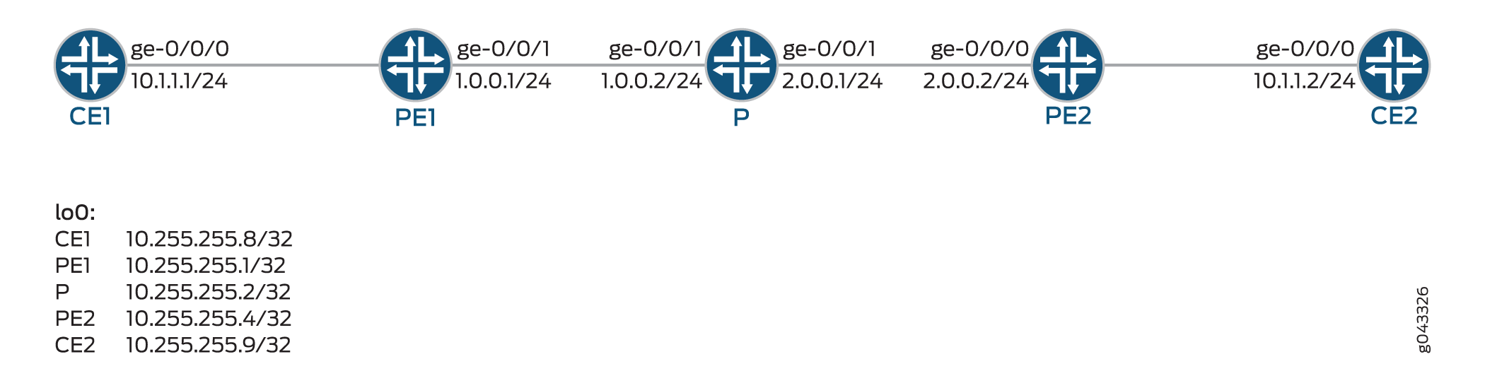
設定
CLIクイックコンフィグレーション
この例をすばやく設定するには、以下のコマンドをコピーしてテキストファイルに貼り付け、改行を削除し、ネットワーク設定に一致させる必要がある詳細情報を変更し、コマンドを [edit] 階層レベルでCLIにコピーアンドペーストして、設定モードから commit を入力します。
CE1
set interfaces ge-0/0/0 vlan-tagging set interfaces ge-0/0/0 unit 600 vlan-id 600 set interfaces ge-0/0/0 unit 600 family inet address 10.1.1.1/24 set interfaces lo0 unit 0 family inet address 10.255.255.8/32
PE1
set interfaces ge-0/0/0 vlan-tagging set interfaces ge-0/0/0 mtu 1600 set interfaces ge-0/0/0 encapsulation vlan-vpls set interfaces ge-0/0/0 unit 600 encapsulation vlan-vpls set interfaces ge-0/0/0 unit 600 vlan-id 600 set interfaces ge-0/0/0 unit 600 family vpls set interfaces ge-0/0/1 unit 0 family inet address 1.0.0.1/24 set interfaces ge-0/0/1 unit 0 family mpls set interfaces lo0 unit 0 family inet address 10.255.255.1/32 set routing-options nonstop-routing set routing-options router-id 10.255.255.1 set routing-options autonomous-system 100 set routing-options forwarding-table export exp-to-frwd set protocols rsvp interface all set protocols rsvp interface ge-0/0/1.0 set protocols rsvp interface lo0.0 set protocols mpls label-switched-path to-pe2 to 10.255.255.4 set protocols mpls interface ge-0/0/1.0 set protocols bgp group vpls-pe type internal set protocols bgp group vpls-pe local-address 10.255.255.1 set protocols bgp group vpls-pe family l2vpn auto-discovery-only set protocols bgp group vpls-pe family l2vpn signaling set protocols bgp group vpls-pe neighbor 10.255.255.4 set protocols bgp group vpls-pe neighbor 10.255.255.2 set protocols ospf traffic-engineering set protocols ospf area 0.0.0.0 interface lo0.0 passive set protocols ospf area 0.0.0.0 interface ge-0/0/1.0 set policy-options policy-statement exp-to-frwd term 0 from community vpls-com set policy-options policy-statement exp-to-frwd term 0 then install-nexthop lsp to-pe2 set policy-options policy-statement exp-to-frwd term 0 then accept set policy-options community vpls-com members target:100:100 set routing-instances vpl1 instance-type vpls set routing-instances vpl1 interface ge-0/0/0.600 set routing-instances vpl1 route-distinguisher 10.255.255.1:100 set routing-instances vpl1 vrf-target target:100:100 set routing-instances vpl1 protocols vpls site-range 10 set routing-instances vpl1 protocols vpls no-tunnel-services set routing-instances vpl1 protocols vpls site vpl1PE1 site-identifier 1 set routing-instances vpl1 protocols vpls flow-label-transmit set routing-instances vpl1 protocols vpls flow-label-receive
P
set interfaces ge-0/0/0 unit 0 family inet address 1.0.0.2/24 set interfaces ge-0/0/0 unit 0 family mpls set interfaces ge-0/0/1 unit 0 family inet address 2.0.0.1/24 set interfaces ge-0/0/1 unit 0 family mpls set interfaces lo0 unit 0 family inet address 10.255.255.2/32 set routing-options router-id 10.255.255.2 set routing-options autonomous-system 100 set protocols rsvp interface ge-0/0/1.0 set protocols rsvp interface ge-0/0/0.0 set protocols rsvp interface lo0.0 set protocols mpls interface ge-0/0/0.0 set protocols mpls interface ge-0/0/1.0 set protocols bgp group vpls-pe type internal set protocols bgp group vpls-pe local-address 10.255.255.2 set protocols bgp group vpls-pe family l2vpn signaling set protocols bgp group vpls-pe neighbor 10.255.255.1 set protocols bgp group vpls-pe neighbor 10.255.255.4 deactivate protocols bgp set protocols ospf traffic-engineering set protocols ospf area 0.0.0.0 interface lo0.0 passive set protocols ospf area 0.0.0.0 interface ge-0/0/0.0 set protocols ospf area 0.0.0.0 interface ge-0/0/1.0
PE2
set interfaces ge-0/0/0 unit 0 family inet address 2.0.0.2/24 set interfaces ge-0/0/0 unit 0 family mpls set interfaces ge-0/0/1 vlan-tagging set interfaces ge-0/0/1 mtu 1600 set interfaces ge-0/0/1 encapsulation vlan-vpls set interfaces ge-0/0/1 unit 600 encapsulation vlan-vpls set interfaces ge-0/0/1 unit 600 vlan-id 600 set interfaces ge-0/0/1 unit 600 family vpls set interfaces lo0 unit 0 family inet address 10.255.255.4/32 set routing-options router-id 10.255.255.4 set routing-options autonomous-system 100 set routing-options forwarding-table export exp-to-frwd set protocols rsvp interface all set protocols rsvp interface ge-0/0/1.0 set protocols rsvp interface lo0.0 set protocols mpls label-switched-path to-pe1 to 10.255.255.1 set protocols mpls interface ge-0/0/0.0 set protocols bgp group vpls-pe type internal set protocols bgp group vpls-pe local-address 10.255.255.4 set protocols bgp group vpls-pe family l2vpn auto-discovery-only set protocols bgp group vpls-pe family l2vpn signaling set protocols bgp group vpls-pe neighbor 10.255.255.1 set protocols bgp group vpls-pe neighbor 10.255.255.2 set protocols ospf traffic-engineering set protocols ospf area 0.0.0.0 interface lo0.0 passive set protocols ospf area 0.0.0.0 interface ge-0/0/0.0 set policy-options policy-statement exp-to-frwd term 0 from community vpls-com set policy-options policy-statement exp-to-frwd term 0 then install-nexthop lsp to-pe1 set policy-options policy-statement exp-to-frwd term 0 then accept set policy-options community vpls-com members target:100:100 set routing-instances vpl1 instance-type vpls set routing-instances vpl1 interface ge-0/0/1.600 set routing-instances vpl1 route-distinguisher 10.255.255.4:100 set routing-instances vpl1 vrf-target target:100:100 set routing-instances vpl1 protocols vpls site-range 10 set routing-instances vpl1 protocols vpls no-tunnel-services set routing-instances vpl1 protocols vpls site vpl1PE2 site-identifier 2 set routing-instances vpl1 protocols vpls flow-label-transmit set routing-instances vpl1 protocols vpls flow-label-receive
CE2
set interfaces ge-0/0/0 vlan-tagging set interfaces ge-0/0/0 unit 600 vlan-id 600 set interfaces ge-0/0/0 unit 600 family inet address 10.1.1.2/24 set interfaces lo0 unit 0 family inet address 10.255.255.9/32
PE1の設定
ステップバイステップの手順
次の例では、設定階層内のさまざまなレベルに移動する必要があります。CLIのナビゲーションについては、『Junos OS CLIユーザーガイド』の「設定モードでのCLIエディターの使用」を参照してください。
デバイスPE1を設定するには:
-
インターフェイスを設定します。
[edit interfaces] user@PE1# set ge-0/0/0 vlan-tagging user@PE1# set ge-0/0/0 mtu 1600 user@PE1# set ge-0/0/0 encapsulation vlan-vpls user@PE1# set ge-0/0/0 unit 600 encapsulation vlan-vpls user@PE1# set ge-0/0/0 unit 600 vlan-id 600 user@PE1# set ge-0/0/0 unit 600 family vpls user@PE1# set ge-0/0/1 unit 0 family inet address 1.0.0.1/24 user@PE1# set ge-0/0/1 unit 0 family mpls user@PE1# set lo0 unit 0 family inet address 10.255.255.1/32
-
ノンストップルーティングを設定し、ルーターIDを設定します。
[edit routing-options] user@PE1# set nonstop-routing user@PE1# set router-id 10.255.255.1
-
自律システム(AS)番号を設定し、exportステートメントを使用してローカルルーターの転送テーブルにポリシーを適用します。
[edit routing-options] user@PE1# set autonomous-system 100 user@PE1# set forwarding-table export exp-to-frwd
-
インターフェイスにRSVPプロトコルを設定します。
[edit protocols rsvp] user@PE1# set interface all user@PE1# set interface ge-0/0/1.0 user@PE1# set interface lo0.0
-
ラベルスイッチパス属性をMPLSプロトコルに適用し、インターフェイスを設定します。
[edit protocols mpls] user@PE1# set label-switched-path to-pe2 to 10.255.255.4 user@PE1# set interface ge-0/0/1.0
-
ピアグループを定義し、ピアグループ
vpls-pe用のBGPセッションのローカルエンドのアドレスを設定します。[edit protocols bgp group vpls-pe] user@PE1# set type internal user@PE1# set local-address 10.255.255.1
-
アップデートにおけるNLRIのプロトコルファミリーの属性を設定します。
[edit protocols bgp group vpls-pe family l2vpn] user@PE1# set auto-discovery-only user@PE1# set signaling
-
ピアグループ
vpls-peのネイバーを設定します。[edit protocols bgp group vpls-pe] user@PE1# set neighbor 10.255.255.4 user@PE1# set neighbor 10.255.255.2
-
トラフィック エンジニアリングを設定し、OSPFエリア0.0.0.0のインターフェイスを設定します。
[edit protocols ospf] user@PE1# set traffic-engineering user@PE1# set area 0.0.0.0 interface lo0.0 passive user@PE1# set area 0.0.0.0 interface ge-0/0/1.0
-
ルーティングポリシーとBGPコミュニティ情報を設定します。
[edit policy-options ] user@PE1# set policy-statement exp-to-frwd term 0 from community vpls-com user@PE1# set policy-statement exp-to-frwd term 0 then install-nexthop lsp to-pe2 user@PE1# set policy-statement exp-to-frwd term 0 then accept user@PE1# set community vpls-com members target:100:100
-
ルーティングインスタンスのタイプを設定し、インターフェイスを設定します。
[edit routing-instances vp1] user@PE1# set instance-type vpls user@PE1# set interface ge-0/0/0.600
-
インスタンス
vpl1のルート識別子を設定し、VRFのターゲットコミュニティを設定します。[edit routing-instances vpl1] user@PE1# set route-distinguisher 10.255.255.1:100 user@PE1# set vrf-target target:100:100
-
VPLSドメインに最大サイト識別子を割り当てます。
[edit routing-instances vp1 protocols vpls] user@PE1# set site-range 10
-
VPLSインスタンスのトンネルサービスを使用しないようにVPLSプロトコルを設定し、プロバイダー機器に接続されたサイトにサイト識別子を割り当てます。
[edit routing-instances vp1 protocols vpls] user@PE1# set no-tunnel-services user@PE1# set site vpl1PE1 site-identifier 1
-
ルーティングインスタンスのVPLSプロトコルを設定し、リモートPEへの受信方向のフローラベルをポップするアドバタイズ機能を提供し、また、リモートPEへの送信方向のフローラベルをプッシュするアドバタイズ機能も提供します。
[edit routing-instances vp1 protocols vpls] user@PE1# set flow-label-receive user@PE1# set flow-label-transmit
結果
設定モードから、 show interfaces、 show protocols、 show policy-options、 show routing-instances、 show routing-options コマンドを入力して設定を確認します。出力に意図した設定が表示されない場合は、この例の手順を繰り返して設定を修正します。
user@PE1# show interfaces
ge-0/0/0 {
vlan-tagging;
mtu 1600;
encapsulation vlan-vpls;
unit 600 {
encapsulation vlan-vpls;
vlan-id 600;
family vpls;
}
}
ge-0/0/1 {
unit 0 {
family inet {
address 1.0.0.1/24;
}
family mpls;
}
}
lo0 {
unit 0 {
family inet {
address 10.255.255.1/32;
}
}
}
user@PE1# show protocols
rsvp {
interface all;
interface ge-0/0/1.0;
interface lo0.0;
}
mpls {
label-switched-path to-pe2 {
to 10.255.255.4;
}
interface ge-0/0/1.0;
}
bgp {
group vpls-pe {
type internal;
local-address 10.255.255.1;
family l2vpn {
auto-discovery-only;
signaling;
}
neighbor 10.255.255.4;
neighbor 10.255.255.2;
}
}
ospf {
traffic-engineering;
area 0.0.0.0 {
interface lo0.0 {
passive;
}
interface ge-0/0/1.0;
}
}
user@PE1# show policy-options
policy-statement exp-to-frwd {
term 0 {
from community vpls-com;
then {
install-nexthop lsp to-pe2;
accept;
}
}
}
community vpls-com members target:100:100;
user@PE1# show routing-instances
vpl1 {
instance-type vpls;
interface ge-0/0/0.600;
route-distinguisher 10.255.255.1:100;
vrf-target target:100:100;
protocols {
vpls {
site-range 10;
no-tunnel-services;
site vpl1PE1 {
site-identifier 1;
}
flow-label-transmit;
flow-label-receive;
}
}
}
user@PE1# show routing-options
nonstop-routing;
router-id 10.255.255.1;
autonomous-system 100;
forwarding-table {
export exp-to-frwd;
}
PE2の設定
ステップバイステップの手順
次の例では、設定階層内のさまざまなレベルに移動する必要があります。CLIのナビゲーションについては、『Junos OS CLIユーザーガイド』の「設定モードでのCLIエディターの使用」を参照してください。
デバイスPE2を設定するには:
-
インターフェイスを設定します。
[edit interfaces] user@PE2# set ge-0/0/0 unit 0 family inet address 2.0.0.2/24 user@PE2# set ge-0/0/0 unit 0 family mpls user@PE2# set ge-0/0/1 vlan-tagging user@PE2# set ge-0/0/1 mtu 1600 user@PE2# set ge-0/0/1 encapsulation vlan-vpls user@PE2# set ge-0/0/1 unit 600 encapsulation vlan-vpls user@PE2# set ge-0/0/1 unit 600 vlan-id 600 user@PE2# set ge-0/0/1 unit 600 family vpls user@PE2# set lo0 unit 0 family inet address 10.255.255.4/32
-
ルーターIDを設定します。
[edit routing-options] user@PE2# set router-id 10.255.255.4
-
自律システム(AS)番号を設定し、exportステートメントを使用してローカルルーターの転送テーブルにポリシーを適用します。
[edit routing-options] user@PE2# set autonomous-system 100 user@PE2# set forwarding-table export exp-to-frwd
-
インターフェイスにRSVPプロトコルを設定します。
[edit protocols rsvp] user@PE2# set interface all user@PE2# set interface ge-0/0/1.0 user@PE2# set interface lo0.0
-
ラベルスイッチパス属性をMPLSプロトコルに適用し、インターフェイスを設定します。
[edit protocols mpls] user@PE2# set label-switched-path to-pe1 to 10.255.255.1 user@PE2# set interface ge-0/0/0.0
-
ピアグループを定義し、ピアグループ
vpls-pe用のBGPセッションのローカルエンドアドレスを設定します。[edit protocols bgp group vpls-pe] user@PE2# set type internal user@PE2# set local-address 10.255.255.4
-
アップデートにおけるNLRIのプロトコルファミリーの属性を設定します。
[edit protocols bgp group vpls-pe] user@PE2# set family l2vpn auto-discovery-only user@PE2# set family l2vpn signaling
-
ピアグループ
vpls-peのネイバーを設定します。[edit protocols bgp group vpls-pe] user@PE2# set neighbor 10.255.255.1 user@PE2# set neighbor 10.255.255.2
-
トラフィック エンジニアリングを設定し、OSPFエリア0.0.0.0のインターフェイスを設定します。
[edit protocols ospf] user@PE2# set traffic-engineering user@PE2# set area 0.0.0.0 interface lo0.0 passive user@PE2# set area 0.0.0.0 interface ge-0/0/0.0
-
ルーティングポリシーとBGPコミュニティ情報を設定します。
[edit policy-options ] user@PE2# set policy-statement exp-to-frwd term 0 from community vpls-com user@PE2# set policy-statement exp-to-frwd term 0 then install-nexthop lsp to-pe1 user@PE2# set policy-statement exp-to-frwd term 0 then accept user@PE2# set community vpls-com members target:100:100
-
ルーティングインスタンスのタイプを設定し、インターフェイスを設定します。
[edit routing-instances vpl1] user@PE2# set instance-type vpls user@PE2# set interface ge-0/0/1.600
-
インスタンス
vp11のルート識別子を設定し、VRFのターゲットコミュニティを設定します。[edit routing-instances vpl1] user@PE2# set route-distinguisher 10.255.255.4:100 user@PE2# set vrf-target target:100:100
-
VPLSドメインに最大サイト識別子を割り当てます。
[edit routing-instances vpl1 protocols vpls] user@PE2# set site-range 10
-
VPLSインスタンスのトンネルサービスを使用しないようにVPLSプロトコルを設定し、プロバイダー機器に接続されたサイトにサイト識別子を割り当てます。
[edit routing-instances vpl1 protocols vpls] user@PE2# set no-tunnel-services user@PE2# set site vpl1PE2 site-identifier 2
-
ルーティングインスタンスのVPLSプロトコルを設定し、リモートPEへの受信方向のフローラベルをポップするアドバタイズ機能を提供し、また、リモートPEへの送信方向のフローラベルをプッシュするアドバタイズ機能も提供します。
[edit routing-instances vpl1 protocols vpls] user@PE2# set flow-label-transmit user@PE2# set flow-label-receive
結果
設定モードから、 show interfaces、 show protocols、 show policy-options、 show routing-instances、 show routing-options コマンドを入力して設定を確認します。出力に意図した設定が表示されない場合は、この例の手順を繰り返して設定を修正します。
user@PE2# show interfaces
ge-0/0/0 {
unit 0 {
family inet {
address 2.0.0.2/24;
}
family mpls;
}
}
ge-0/0/1 {
vlan-tagging;
mtu 1600;
encapsulation vlan-vpls;
unit 600 {
encapsulation vlan-vpls;
vlan-id 600;
family vpls;
}
}
lo0 {
unit 0 {
family inet {
address 10.255.255.4/32;
}
}
}
user@PE2# show protocols
rsvp {
interface all;
interface ge-0/0/1.0;
interface lo0.0;
}
mpls {
label-switched-path to-pe1 {
to 10.255.255.1;
}
interface ge-0/0/0.0;
}
bgp {
group vpls-pe {
type internal;
local-address 10.255.255.4;
family l2vpn {
auto-discovery-only;
signaling;
}
neighbor 10.255.255.1;
neighbor 10.255.255.2;
}
}
ospf {
traffic-engineering;
area 0.0.0.0 {
interface lo0.0 {
passive;
}
interface ge-0/0/0.0;
}
}
user@PE2# show policy-options
policy-statement exp-to-frwd {
term 0 {
from community vpls-com;
then {
install-nexthop lsp to-pe1;
accept;
}
}
}
community vpls-com members target:100:100;
user@PE2# show routing-instances
vpl1 {
instance-type vpls;
interface ge-0/0/1.600;
route-distinguisher 10.255.255.4:100;
vrf-target target:100:100;
protocols {
vpls {
site-range 10;
no-tunnel-services;
site vpl1PE2 {
site-identifier 2;
}
flow-label-transmit;
flow-label-receive;
}
}
}
user@PE2# show routing-options
router-id 10.255.255.4;
autonomous-system 100;
forwarding-table {
export exp-to-frwd;
}
検証
設定が正常に機能していることを確認します。
VPLS接続情報の検証
目的
VPLSの接続情報を確認します。
アクション
運用モードから、 show vpls connections コマンドを実行してVPLSの接続情報を表示します。
user@PE1> show vpls connections
Layer-2 VPN connections:
Legend for connection status (St)
EI -- encapsulation invalid NC -- interface encapsulation not CCC/TCC/VPLS
EM -- encapsulation mismatch WE -- interface and instance encaps not same
VC-Dn -- Virtual circuit down NP -- interface hardware not present
CM -- control-word mismatch -> -- only outbound connection is up
CN -- circuit not provisioned <- -- only inbound connection is up
OR -- out of range Up -- operational
OL -- no outgoing label Dn -- down
LD -- local site signaled down CF -- call admission control failure
RD -- remote site signaled down SC -- local and remote site ID collision
LN -- local site not designated LM -- local site ID not minimum designated
RN -- remote site not designated RM -- remote site ID not minimum designated
XX -- unknown connection status IL -- no incoming label
MM -- MTU mismatch MI -- Mesh-Group ID not available
BK -- Backup connection ST -- Standby connection
PF -- Profile parse failure PB -- Profile busy
RS -- remote site standby SN -- Static Neighbor
LB -- Local site not best-site RB -- Remote site not best-site
VM -- VLAN ID mismatch
Legend for interface status
Up -- operational
Dn -- down
Instance: vpl1
Edge protection: Not-Primary
Local site: vpl1PE1 (1)
connection-site Type St Time last up # Up trans
2 rmt Up Jun 17 11:38:14 2015 1
Remote PE: 10.255.255.4, Negotiated control-word: No
Incoming label: 262146, Outgoing label: 262145
Local interface: lsi.1048576, Status: Up, Encapsulation: VPLS
Description: Intf - vpls vpl1 local site 1 remote site 2
Flow Label Transmit: Yes, Flow Label Receive: Yes
意味
出力には、VPLSの接続情報とフローラベルの受信およびフローラベルの送信情報が表示されます。
検証
設定が正常に機能していることを確認します。
VPLS接続情報の検証
目的
VPLSの接続情報を確認します。
アクション
運用モードから、 show vpls connections コマンドを実行してVPLSの接続情報を表示します。
user@PE2> show vpls connections
Layer-2 VPN connections:
Legend for connection status (St)
EI -- encapsulation invalid NC -- interface encapsulation not CCC/TCC/VPLS
EM -- encapsulation mismatch WE -- interface and instance encaps not same
VC-Dn -- Virtual circuit down NP -- interface hardware not present
CM -- control-word mismatch -> -- only outbound connection is up
CN -- circuit not provisioned <- -- only inbound connection is up
OR -- out of range Up -- operational
OL -- no outgoing label Dn -- down
LD -- local site signaled down CF -- call admission control failure
RD -- remote site signaled down SC -- local and remote site ID collision
LN -- local site not designated LM -- local site ID not minimum designated
RN -- remote site not designated RM -- remote site ID not minimum designated
XX -- unknown connection status IL -- no incoming label
MM -- MTU mismatch MI -- Mesh-Group ID not available
BK -- Backup connection ST -- Standby connection
PF -- Profile parse failure PB -- Profile busy
RS -- remote site standby SN -- Static Neighbor
LB -- Local site not best-site RB -- Remote site not best-site
VM -- VLAN ID mismatch
Legend for interface status
Up -- operational
Dn -- down
Instance: vpl1
Edge protection: Not-Primary
Local site: vpl1PE2 (2)
connection-site Type St Time last up # Up trans
1 rmt Up Jun 17 11:38:14 2015 1
Remote PE: 10.255.255.1, Negotiated control-word: No
Incoming label: 262145, Outgoing label: 262146
Local interface: lsi.1048576, Status: Up, Encapsulation: VPLS
Description: Intf - vpls vpl1 local site 2 remote site 1
Flow Label Transmit: Yes, Flow Label Receive: Yes
意味
出力には、VPLSの接続情報とフローラベルの受信およびフローラベルの送信情報が表示されます。
変更履歴テーブル
サポートされる機能は、使用しているプラットフォームとリリースによって決まります。 機能エクスプローラー を使用して、機能がお使いのプラットフォームでサポートされているかどうかを確認します。
[edit protocols bgp]階層レベルでグローバルにサポートされています。一部の BGP グループとネイバーでマルチパスを選択的に無効にできます。グループまたは特定のBGPネイバーに対してマルチパスオプションを無効にするには
[edit protocols bgp group group-name multipath]階層レベルに
disableを含めます。
[edit protocols bgp]階層レベルで
defer-initial-multipath-buildを設定します。または、階層レベルで設定ステートメントを使用して
multipath-build-priorityBGPマルチパスビルドジョブの優先度を下げ
[edit protocols bgp]RIB学習を高速化することもできます。