BGPルートリフレクタ
BGPルートリフレクタについて
このトピックでは、BGPルートリフレクタを使用して、設定を簡素化し、スケーリングを支援する方法について説明します。
BGP自律システム(AS)では、すべてのAS境界ルーターにルートを分散する必要があります。BGP(境界ゲートウェイプロトコル)は、内部 BGP(IBGP)ピアリング セッションを通じてこれを実現します。デフォルトでは、あるIBGPピアから学習したルートは、他のIBGPピアにはアドバタイズされません。この制限では、ルートを完全に可視化するために、AS内のすべてのルーター間でIBGPセッションのフルメッシュが必要です。
ただし、フルメッシュを維持すると、構成が複雑になり、拡張性が制限されます。新しいIBGPピアは、AS内の他のすべてのピアとセッションを確立する必要があります。フルメッシュに必要なセッションの総数は、v*(v-1)/2の式を使用して計算されます。 ここで、v はBGPピアの数を表します。
フルメッシュでは、構成のオーバーヘッドに加えて、ルートのスケーリングも向上する可能性があります。すべてのIBGPピアは、ネットワーク内のその場所に最適ではないルートが多くであっても、すべてのルートを受信します。
RFC 4456で定義されているBGPルートリフレクションは、IBGPフルメッシュトポロジーのスケーラビリティの課題に対処します。ルートリフレクションにより、ルートリフレクタ(RR)と呼ばれるルーターが、あるIBGPピアから他のIBGPピアに学習したルートを再分配することができます。これにより、ルートのIBGPからIBGPへのアドバタイズを防止するデフォルトのBGPルールが緩和されます。
ルートリフレクションはルーティングループの可能性をもたらすため、RFC 4456では、ループ防止と一貫したパス選択を保証する2つの新しいBGPパス属性を定義しています。
ORIGINATOR_ID - 最初にルートをアドバタイズしたBGPネイバーのルーター IDを識別します。ORIGINATOR_ID属性は、ルートが最初に反映された場合にのみアタッチされます。
CLUSTER_LIST - ネットワークを伝送するルートを反映したルートリフレクタのクラスター IDを記録します。
これらの属性が BGP 最適パス選択にどのように影響するかについては、 BGP パス選択についてを参照してください。
内部BGP(IBGP)フルメッシュ要件により、ほとんどのネットワークではルートリフレクタを使用して設定を簡素化します。ルートリフレクタを使用して、ルーターはクラスターにグループ化され、自律システムに固有の数値識別子によって識別されます。クラスター内では、単一のルーター(ルートリフレクタ)から各内部ピアへのBGPセッションを設定する必要があります。この設定では、IBGPフルメッシュ要件を満たしています。
ASでルートリフレクションを使用するには、1つ以上のルーターをルートリフレクタとして指定します。通常は、POP(ポイントオブプレゼンス)ごとに1つを指定します。ルートリフレクタには、内部ピアから他の内部ピアに再度アドバタイズする機能があります。ルートリフレクションでは、すべての内部ピアが相互に完全にメッシュ化される必要はなく、ルートリフレクタがすべての内部ピアで完全にメッシュ化される必要があります。ルートリフレクタとそのすべての内部ピアは、 図1に示すようにクラスターを形成します。
一部のジュニパーネットワークスデバイスでは、ルートリフレクタを使用する各デバイスに高度なBGP機能ライセンスがインストールされている必要があります。ライセンスの詳細については、 『ソフトウェアのインストールおよびアップグレードガイド』を参照してください。
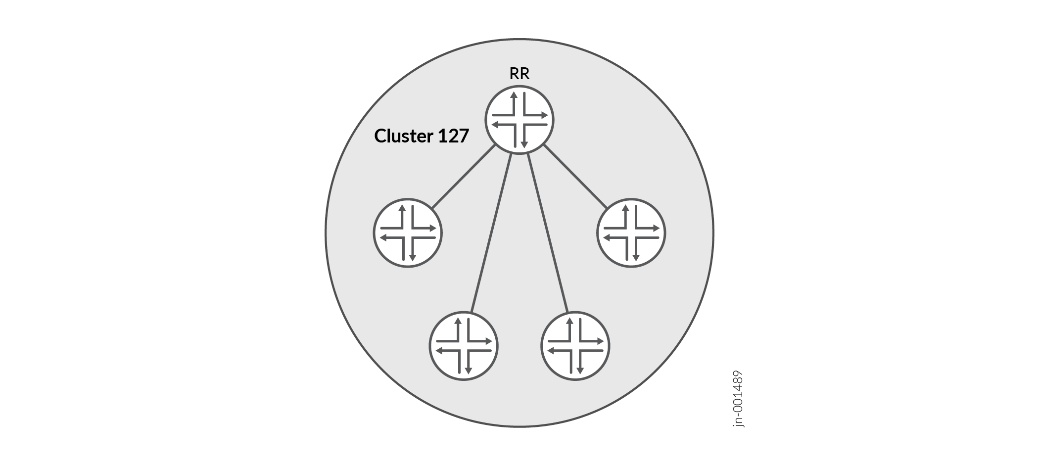
図1は、クラスター127のルートリフレクタとして設定されたルーターRRを示しています。その他のルーターは、クラスター内の内部ピアとして指定されています。BGPルートは、いずれかの内部ピアによってルーターRRにアドバタイズされます。その後、RR は、これらのルートをクラスター内の他のすべてのピアに再アドバタイズします。
ルートリフレクタのフルメッシュを設定することで、複数のクラスタを設定し、それらをリンクすることができます( 図2を参照)。
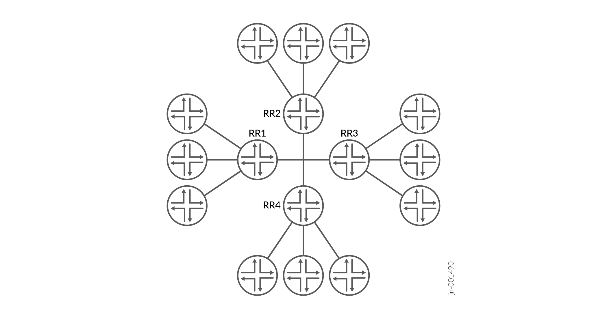
図2は、ルートリフレクタRR1、RR2、RR3、およびRR4をフルメッシュされた内部ピアとして示しています。ルーターがRR1にルートをアドバタイズすると、RR1が他のルートリフレクタにルートを再度アドバタイズします。これにより、AS内の残りのルーターにルートが再度アドバタイズされます。ルートリフレクションにより、フルメッシュ要件によって発生するスケーリングの問題なしに、ルートをAS全体に伝送できます。
複数のクラスターをサポートするルートリフレクタは、非クライアントルーターから同じクラスターIDを持つルートを受信しません。そのため、他のクラスターへのルートを反映するために、冗長RRに異なるクラスターIDを設定する必要があります。
クライアントは、ルートリフレクタからルートを受信するIBGPルーターです。非クライアントは、別のIBGPネイバーです。ルートリフレクタは、非クライアントから学習したルートを、非クライアントに対してではなく、そのクライアントに対してのみアドバタイズします。ただし、ルートリフレクタは、クライアントから学習したルートをクライアントと非クライアントの両方にアドバタイズします。
しかし、クラスターが大きくなるにつれて、ルートリフレクタを使用したフルメッシュは、ルートリフレクタ間のフルメッシュと同様に、拡張が困難になります。この問題を相殺するために、ルーターのクラスターを、階層ルートリフレクションを行うために、クラスターのクラスターにまとめてグループ化することができます( 図3を参照)。
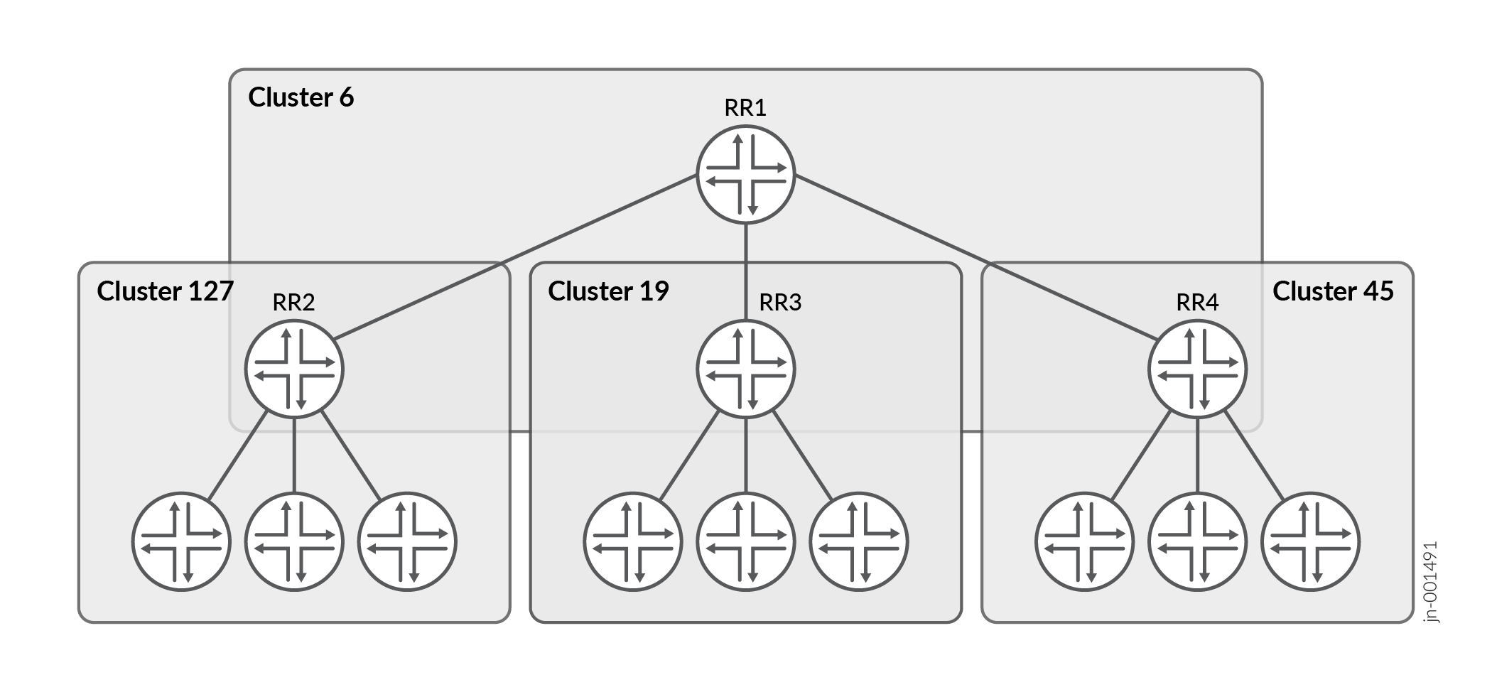
図3は、クラスター127、19、および45のルートリフレクタとして、RR2、RR3、およびRR4を示しています。ネットワーク管理者は、これらのルートリフレクタを完全にメッシュ化するのではなく、RR1がルートリフレクタである別のクラスター(クラスター6)の一部として設定しています。ルーターがRR2にルートをアドバタイズすると、RR2は自身のクラスター内のすべてのルーターにルートを再アドバタイズし、その後RR1にルートを再アドバタイズします。RR1は、そのクラスター内のルーターにルートを再アドバタイズし、これらのルーターはクラスターを介してルートを伝送します。
関連項目
非転送ルートリフレクタ
多くのネットワークでは、BGPルートリフレクタはスケーラビリティを向上させるために導入されていますが、トラフィックの転送には直接関与していません。これらのルートリフレクタは、データ転送に関与することなくBGPコントロールプレーン機能を維持します。ルートリフレクタがトラフィックパスにない場合、リフレクタは、リフレクションしたルートを転送テーブルにインストールする必要はありません。このようなデバイスは、非転送ルートリフレクタと呼ばれます。
非転送ルートリフレクタは、以下のいずれかの方法で設定できます。
-
no-installステートメントの使用 – Junos OSリリース15.1で導入されたno-installステートメントは、BGPルートが転送テーブルにインストールされないようにします。このオプションは、以下の階層レベルでアドレスファミリーごとに設定できます。[edit protocols bgp family family-name] set no-install
-
転送テーブルエクスポートポリシーの使用 – 15.1より前のJunos OSリリースでは、BGPから学習したルートを拒否する転送テーブルエクスポートポリシーを設定することで、同様の動作を実現できます。
非転送ルートリフレクタは、特に大規模なサービスプロバイダネットワークにおいて、主にコントロールプレーンルーターとして機能するデバイスのリソース負荷を軽減するのに役立ちます。
例:ルートリフレクタの設定
この例では、ルートリフレクタを設定する方法を示します。
要件
この例を設定する前に、デバイスの初期化以外の特別な設定は必要ありません。
概要
一般に、内部 BGP(IBGP)対応デバイスは、IBGP が他の IBGP 対応デバイスに更新を再アドバタイズしないため、完全にメッシュ化する必要があります。フルメッシュは、IBGP対応機器に複数の neighbor ステートメントを設定することで実現する論理的なメッシュです。フル メッシュは必ずしも物理的なフルメッシュとは限りません。フルメッシュ(論理的または物理的)を維持することは、大規模な展開ではうまく拡張できません。
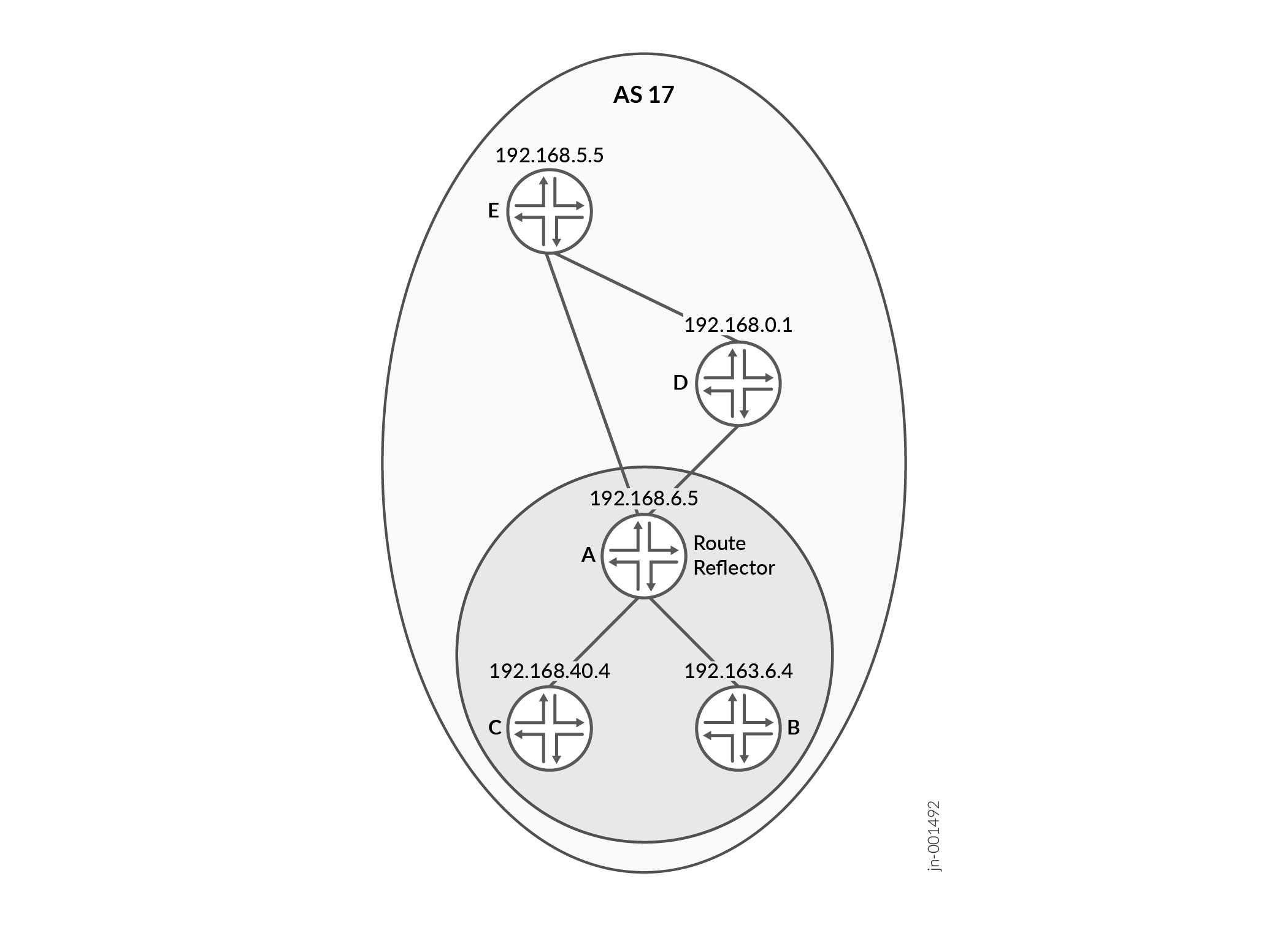
図4 は、デバイスAがルートリフレクタとして動作するIBGPネットワークを示しています。機器 B と機器 C は、ルート リフレクタのクライアントです。デバイス D とデバイス E はクラスターの外にあるため、ルート リフレクタの非クライアントです。
デバイスA(ルートリフレクタ)では、クライアント(デバイスBおよびデバイスC)および非クライアント(デバイスDおよびデバイスE)に対して neighbor ステートメントを含めることで、すべてのIBGP対応デバイスとピア関係を形成する必要があります。また、 cluster ステートメントとクラスター識別子を含める必要があります。クラスター識別子は、任意の32ビット値にすることができます。この例では、ルートリフレクタのループバックインターフェイスIPアドレスを使用しています。
ルートリフレクタクライアントである装置Bと装置Cでは、ルートリフレクタである装置Aとピア関係を形成する neighbor ステートメントが1つだけ必要です。
非クライアントであるデバイスDとデバイスEでは、非クライアントデバイス(DtoE、EtoD)ごとに neighbor ステートメントが必要です。また、ルートリフレクタ(D-to-A、E-to-A)用の neighbor ステートメントも必要です。デバイスDとデバイスEは、クライアントデバイス(デバイスBとデバイスC)に対する neighbor ステートメントは必要ありません。
デバイスDとデバイスEは、互いにピア関係を明示的に設定しているため、非クライアントとみなされます。RRルートリフレクタクライアントにするには、デバイスDの設定から neighbor 192.168.5.5 ステートメントを削除し、デバイスEの設定から neighbor 192.168.0.1 ステートメントを削除します。
 を使用したIBGPネットワーク
設定
手順
CLIクイックコンフィグレーション
この例をすばやく設定するには、以下のコマンドをコピーしてテキスト ファイルに貼り付け、改行を削除して、ネットワーク構成に合わせて必要な詳細を変更し、 [edit] 階層レベルのCLIにコマンドをコピー アンド ペーストします。
この例では、 send-ospf エクスポートポリシーを使用して、OSPFで学習したルートをBGPに再配布します。
set protocols bgp group internal-peers export send-ospf
通常、ルートリフレクタの動作には、OSPF の BGP への再配布は必要ありません。ここでは、ルートリフレクタがクライアントにアドバタイズできるBGPルートを作成するためにのみ使用し、シンプルなラボトポロジーでルートリフレクションがどのように動作するかを観察できるようにします。
実稼働環境では、ルートリフレクタは通常、クライアントから学習したBGPルートを反映し、この動作が特に望ましくない限り、IGPルートをBGPに再配布しません。
この例では、ルーターA、D、Eは非クライアントIBGPピアであり、ルートリフレクタクライアントクラスター外で一貫したルート交換を確保するためにフルメッシュで構成されています。
デバイスA
set interfaces fe-0/0/0 unit 1 description to-B
set interfaces fe-0/0/0 unit 1 family inet address 10.10.10.1/30
set interfaces fe-0/0/1 unit 3 description to-D
set interfaces fe-0/0/1 unit 3 family inet address 10.10.10.9/30
set interfaces lo0 unit 1 family inet address 192.168.6.5/32
set protocols bgp group internal-peers type internal
set protocols bgp group internal-peers local-address 192.168.6.5
set protocols bgp group internal-peers export send-ospf
set protocols bgp group internal-peers cluster 192.168.6.5
set protocols bgp group internal-peers neighbor 192.163.6.4
set protocols bgp group internal-peers neighbor 192.168.40.4
set protocols bgp group internal-peers neighbor 192.168.0.1
set protocols bgp group internal-peers neighbor 192.168.5.5
set protocols ospf area 0.0.0.0 interface lo0.1 passive
set protocols ospf area 0.0.0.0 interface fe-0/0/0.1
set protocols ospf area 0.0.0.0 interface fe-0/0/1.3
set policy-options policy-statement send-ospf term 2 from protocol ospf
set policy-options policy-statement send-ospf term 2 then accept
set routing-options router-id 192.168.6.5
set routing-options autonomous-system 17
デバイスB
set interfaces fe-0/0/0 unit 2 description to-A
set interfaces fe-0/0/0 unit 2 family inet address 10.10.10.2/30
set interfaces fe-0/0/1 unit 5 description to-C
set interfaces fe-0/0/1 unit 5 family inet address 10.10.10.5/30
set interfaces lo0 unit 2 family inet address 192.163.6.4/32
set protocols bgp group internal-peers type internal
set protocols bgp group internal-peers local-address 192.163.6.4
set protocols bgp group internal-peers export send-ospf
set protocols bgp group internal-peers neighbor 192.168.6.5
set protocols ospf area 0.0.0.0 interface lo0.2 passive
set protocols ospf area 0.0.0.0 interface fe-0/0/0.2
set protocols ospf area 0.0.0.0 interface fe-0/0/1.5
set policy-options policy-statement send-ospf term 2 from protocol ospf
set policy-options policy-statement send-ospf term 2 then accept
set routing-options router-id 192.163.6.4
set routing-options autonomous-system 17
デバイスC
set interfaces fe-0/0/0 unit 6 description to-B
set interfaces fe-0/0/0 unit 6 family inet address 10.10.10.6/30
set interfaces lo0 unit 3 family inet address 192.168.40.4/32
set protocols bgp group internal-peers type internal
set protocols bgp group internal-peers local-address 192.168.40.4
set protocols bgp group internal-peers export send-ospf
set protocols bgp group internal-peers neighbor 192.168.6.5
set protocols ospf area 0.0.0.0 interface lo0.3 passive
set protocols ospf area 0.0.0.0 interface fe-0/0/0.6
set policy-options policy-statement send-ospf term 2 from protocol ospf
set policy-options policy-statement send-ospf term 2 then accept
set routing-options router-id 192.168.40.4
set routing-options autonomous-system 17
デバイスD
set interfaces fe-0/0/0 unit 4 description to-A
set interfaces fe-0/0/0 unit 4 family inet address 10.10.10.10/30
set interfaces fe-0/0/1 unit 7 description to-E
set interfaces fe-0/0/1 unit 7 family inet address 10.10.10.13/30
set interfaces lo0 unit 4 family inet address 192.168.0.1/32
set protocols bgp group internal-peers type internal
set protocols bgp group internal-peers local-address 192.168.0.1
set protocols bgp group internal-peers export send-ospf
set protocols bgp group internal-peers neighbor 192.168.6.5
set protocols bgp group internal-peers neighbor 192.168.5.5
set protocols ospf area 0.0.0.0 interface lo0.4 passive
set protocols ospf area 0.0.0.0 interface fe-0/0/0.4
set protocols ospf area 0.0.0.0 interface fe-0/0/1.7
set policy-options policy-statement send-ospf term 2 from protocol ospf
set policy-options policy-statement send-ospf term 2 then accept
set routing-options router-id 192.168.0.1
set routing-options autonomous-system 17
デバイスE
set interfaces fe-0/0/0 unit 8 description to-D
set interfaces fe-0/0/0 unit 8 family inet address 10.10.10.14/30
set interfaces lo0 unit 5 family inet address 192.168.5.5/32
set protocols bgp group internal-peers type internal
set protocols bgp group internal-peers local-address 192.168.5.5
set protocols bgp group internal-peers export send-ospf
set protocols bgp group internal-peers neighbor 192.168.0.1
set protocols bgp group internal-peers neighbor 192.168.6.5
set protocols ospf area 0.0.0.0 interface lo0.5 passive
set protocols ospf area 0.0.0.0 interface fe-0/0/0.8
set policy-options policy-statement send-ospf term 2 from protocol ospf
set policy-options policy-statement send-ospf term 2 then accept
set routing-options router-id 192.168.5.5
set routing-options autonomous-system 17
ステップバイステップの手順
ルートリフレクタの設定
ステップバイステップの手順
次の例では、設定階層のさまざまなレベルに移動する必要があります。CLIのナビゲーションについては、『Junos OS CLIユーザーガイド』の「設定モードでのCLIエディタの使用」を参照してください。
ジュニパーネットワークスデバイスAをルートリフレクタとして使用して、ネットワークにIBGPを設定するには:
-
インターフェイスを設定します。
[edit interfaces]
user@A# set fe-0/0/0 unit 1 description to-B
user@A# set fe-0/0/0 unit 1 family inet address 10.10.10.1/30
user@A# set fe-0/0/1 unit 3 description to-D
user@A# set fe-0/0/1 unit 3 family inet address 10.10.10.9/30
user@A# set lo0 unit 1 family inet address 192.168.6.5/32
-
クラスター識別子や自律システム(AS)内のすべてのIBGP対応デバイスとのネイバー関係などのBGPを設定します。
また、OSPFルートをBGPに再配布するポリシーも適用します。
[edit protocols bgp group internal-peers]
user@A# set type internal
user@A# set local-address 192.168.6.5
user@A# set export send-ospf
user@A# set cluster 192.168.6.5
user@A# set neighbor192.163.6.4
user@A# set neighbor 192.168.40.4
user@A# set neighbor 192.168.0.1
user@A# set neighbor 192.168.5.5
-
スタティックルーティングまたは内部ゲートウェイプロトコル(IGP)を設定します。
この例では、OSPFを使用しています。
[edit protocols ospf area 0.0.0.0]
user@A# set interface lo0.1 passive
user@A# set interface fe-0/0/0.1
user@A# set interface fe-0/0/1.3
-
OSPFルートをBGPに再配布するポリシーを設定します。
[edit  policy-options policy-statement send-ospf term 2]
user@A# set from protocol ospf
user@A# set then accept
-
ルーターIDと自律システム(AS)番号を設定します。
[edit routing-options]
user@A# set router-id 192.168.6.5
user@A# set autonomous-system 17
結果
設定モードから、 show interfaces、 show protocols、 show policy-options、 show routing-options コマンドを入力して設定を確認します。出力に意図した設定が表示されない場合は、この例の手順を繰り返して設定を修正します。
user@A# show interfaces
fe-0/0/0 {
    unit 1 {
        description to-B;
        family inet {
            address 10.10.10.1/30;
        }
    }
}
fe-0/0/1 {
    unit 3 {
        description to-D;
        family inet {
            address 10.10.10.9/30;
        }
    }
}
lo0 {
    unit 1 {
        family inet {
            address 192.168.6.5/32;
        }
    }
}
user@A# show protocols
bgp {
    group internal-peers {
        type internal;
        local-address 192.168.6.5;
        export send-ospf;
        cluster 192.168.6.5;
        neighbor 192.163.6.4;
        neighbor 192.168.40.4;
        neighbor 192.168.0.1;
        neighbor 192.168.5.5;
    }
}
ospf {
    area 0.0.0.0 {
        interface lo0.1 {
            passive;
        }
        interface fe-0/0/0.1;
        interface fe-0/0/1.3;
    }
}
user@A# show policy-options
policy-statement send-ospf {
    term 2 {
        from protocol ospf;
        then accept;
    }
}
user@A# show routing-options
router-id 192.168.6.5;
autonomous-system 17;
デバイスの設定が完了したら、設定モードから commit を入力します。
他の非クライアントデバイスがジュニパーネットワークス製である場合は、構成するクラスター内の各非クライアント BGPピアについて、これらの手順を繰り返します。それ以外の場合は、デバイスのマニュアルを参照してください。
クライアントピアの設定
ステップバイステップの手順
次の例では、設定階層のさまざまなレベルに移動する必要があります。CLIのナビゲーションについては、『Junos OS CLIユーザーガイド』の「設定モードでのCLIエディタの使用」を参照してください。
クライアントピアを設定するには:
-
インターフェイスを設定します。
[edit interfaces]
user@B# set fe-0/0/0 unit 2 description to-A
user@B# set fe-0/0/0 unit 2 family inet address 10.10.10.2/30
user@B# set fe-0/0/1 unit 5 description to-C
user@B# set fe-0/0/1 unit 5 family inet address 10.10.10.5/30
user@B# set lo0 unit 2 family inet address 192.163.6.4/32
-
ルートリフレクタとのBGPネイバー関係を設定します。
また、OSPFルートをBGPに再配布するポリシーも適用します。
[edit protocols bgp group internal-peers]
user@B# set type internal
user@B# set local-address 192.163.6.4
user@B# set export send-ospf
user@B# set neighbor 192.168.6.5
-
OSPFを設定します。
[edit protocols ospf area 0.0.0.0]
user@B# set interface lo0.2 passive
user@B# set interface fe-0/0/0.2
user@B# set interface fe-0/0/1.5
-
OSPFルートをBGPに再配布するポリシーを設定します。
[edit  policy-options policy-statement send-ospf term 2]
user@B# set from protocol ospf
user@B# set then accept
-
ルーターIDとAS番号を設定します。
[edit routing-options]
user@B# set router-id 192.163.6.4
user@B# set autonomous-system 17
結果
設定モードから、 show interfaces、 show protocols、 show policy-options、 show routing-options コマンドを入力して設定を確認します。出力に意図した設定が表示されない場合は、この例の手順を繰り返して設定を修正します。
user@B# show interfaces
fe-0/0/0 {
    unit 2 {
        description to-A;
        family inet {
            address 10.10.10.2/30;
        }
    }
}
fe-0/0/1 {
    unit 5 {
        description to-C;
        family inet {
            address 10.10.10.5/30;
        }
    }
}
lo0 {
    unit 2 {
        family inet {
            address 192.163.6.4/32;
        }
    }
}
user@B# show protocols
bgp {
    group internal-peers {
        type internal;
        local-address 192.163.6.4;
        export send-ospf;
        neighbor 192.168.6.5;
    }
}
ospf {
    area 0.0.0.0 {
        interface lo0.2 {
            passive;
        }
        interface fe-0/0/0.2;
        interface fe-0/0/1.5;
    }
}
user@B# show policy-options
policy-statement send-ospf {
    term 2 {
        from protocol ospf;
        then accept;
    }
}
user@B# show routing-options
router-id 192.163.6.4;
autonomous-system 17;
デバイスの設定が完了したら、設定モードから commit を入力します。
他のクライアントデバイスがジュニパーネットワークスのものである場合は、構成するクラスター内の各クライアントBGPピアに対して、これらの手順を繰り返します。それ以外の場合は、デバイスのマニュアルを参照してください。
非クライアントピアの設定
ステップバイステップの手順
次の例では、設定階層のさまざまなレベルに移動する必要があります。CLIのナビゲーションについては、『Junos OS CLIユーザーガイド』の「設定モードでのCLIエディタの使用」を参照してください。
非クライアントピアを設定するには:
-
インターフェイスを設定します。
[edit interfaces]
user@D# set fe-0/0/0 unit 4 description to-A
user@D# set fe-0/0/0 unit 4 family inet address 10.10.10.10/30
user@D# set fe-0/0/1 unit 7 description to-E
user@D# set fe-0/0/1 unit 7 family inet address 10.10.10.13/30
user@D# set lo0 unit 4 family inet address 192.168.0.1/32
-
RRルートリフレクタおよび他の非クライアントピアとのBGPネイバー関係を設定します。
また、OSPFルートをBGPに再配布するポリシーも適用します。
[edit protocols bgp group internal-peers]
user@D# set type internal
user@D# set local-address 192.168.0.1
user@D# set export send-ospf
user@D# set neighbor 192.168.6.5
user@D# set neighbor 192.168.5.5
-
OSPFを設定します。
[edit protocols ospf area 0.0.0.0]
user@D# set interface lo0.4 passive
user@D# set interface fe-0/0/0.4
user@D# set interface fe-0/0/1.7
-
OSPFルートをBGPに再配布するポリシーを設定します。
[edit  policy-options policy-statement send-ospf term 2]
user@D# set from protocol ospf
user@D# set then accept
-
ルーターIDとAS番号を設定します。
[edit routing-options]
user@D# set router-id 192.168.0.1
user@D# set autonomous-system 17
結果
設定モードから、 show interfaces、 show protocols、 show policy-options、 show routing-options コマンドを入力して設定を確認します。出力に意図した設定が表示されない場合は、この例の手順を繰り返して設定を修正します。
user@D# show interfaces
fe-0/0/0 {
    unit 4 {
        description to-A;
        family inet {
            address 10.10.10.10/30;
        }
    }
}
fe-0/0/1 {
    unit 7 {
        description to-E;
        family inet {
            address 10.10.10.13/30;
        }
    }
}
lo0 {
    unit 4 {
        family inet {
            address 192.168.0.1/32;
        }
    }
}
user@D# show protocols
bgp {
    group internal-peers {
        type internal;
        local-address 192.168.0.1;
        export send-ospf;
        neighbor 192.168.6.5;
        neighbor 192.168.5.5;
    }
}
ospf {
    area 0.0.0.0 {
        interface lo0.4 {
            passive;
        }
        interface fe-0/0/0.4;
        interface fe-0/0/1.7;
    }
}
user@D# show policy-options
policy-statement send-ospf {
    term 2 {
        from protocol ospf;
        then accept;
    }
}
user@D# show routing-options
router-id 192.168.0.1;
autonomous-system 17;
デバイスの設定が完了したら、設定モードから commit を入力します。
他の非クライアントデバイスがジュニパーネットワークス製である場合は、構成するクラスター内の各非クライアント BGPピアについて、これらの手順を繰り返します。それ以外の場合は、デバイスのマニュアルを参照してください。
検証
設定が正常に機能していることを確認します。
BGPネイバーの検証
目的
設定されたインターフェイスで BGP が動作し、各ネイバーアドレスに対して BGP セッションが確立されていることを確認します。
アクション
動作モードから、 show bgp neighbor コマンドを入力します。
user@A> show bgp neighbor
Peer: 192.163.6.4+179 AS 17    Local: 192.168.6.5+62857 AS 17
  Type: Internal    State: Established  (route reflector client)Flags: <Sync>
  Last State: OpenConfirm   Last Event: RecvKeepAlive
  Last Error: None
  Export: [ send-ospf ]
  Options: <Preference LocalAddress Cluster Refresh>
  Local Address: 192.168.6.5 Holdtime: 90 Preference: 170
  Number of flaps: 0
  Peer ID: 192.163.6.4     Local ID: 192.168.6.5       Active Holdtime: 90
  Keepalive Interval: 30         Peer index: 0
  BFD: disabled, down
  NLRI for restart configured on peer: inet-unicast
  NLRI advertised by peer: inet-unicast
  NLRI for this session: inet-unicast
  Peer supports Refresh capability (2)
  Restart time configured on the peer: 120
  Stale routes from peer are kept for: 300
  Restart time requested by this peer: 120
  NLRI that peer supports restart for: inet-unicast
  NLRI that restart is negotiated for: inet-unicast
  NLRI of received end-of-rib markers: inet-unicast
  NLRI of all end-of-rib markers sent: inet-unicast
  Peer supports 4 byte AS extension (peer-as 17)
  Peer does not support Addpath
  Table inet.0 Bit: 10000
    RIB State: BGP restart is complete
    Send state: in sync
    Active prefixes:              0
    Received prefixes:            6
    Accepted prefixes:            1
    Suppressed due to damping:    0
    Advertised prefixes:          6
  Last traffic (seconds): Received 5    Sent 3    Checked 19
  Input messages:  Total 2961   Updates 7       Refreshes 0     Octets 56480
  Output messages: Total 2945   Updates 6       Refreshes 0     Octets 56235
  Output Queue[0]: 0

Peer: 192.168.0.1+179 AS 17    Local: 192.168.6.5+60068 AS 17
  Type: Internal    State: Established  (route reflector client)Flags: <Sync>
  Last State: OpenConfirm   Last Event: RecvKeepAlive
  Last Error: None
  Export: [ send-ospf ]
  Options: <Preference LocalAddress Cluster Refresh>
  Local Address: 192.168.6.5 Holdtime: 90 Preference: 170
  Number of flaps: 0
  Peer ID: 192.168.0.1     Local ID: 192.168.6.5       Active Holdtime: 90
  Keepalive Interval: 30         Peer index: 3
  BFD: disabled, down
  NLRI for restart configured on peer: inet-unicast
  NLRI advertised by peer: inet-unicast
  NLRI for this session: inet-unicast
  Peer supports Refresh capability (2)
  Restart time configured on the peer: 120
  Stale routes from peer are kept for: 300
  Restart time requested by this peer: 120
  NLRI that peer supports restart for: inet-unicast
  NLRI that restart is negotiated for: inet-unicast
  NLRI of received end-of-rib markers: inet-unicast
  NLRI of all end-of-rib markers sent: inet-unicast
  Peer supports 4 byte AS extension (peer-as 17)
  Peer does not support Addpath
  Table inet.0 Bit: 10000
    RIB State: BGP restart is complete
    Send state: in sync
    Active prefixes:              0
    Received prefixes:            6
    Accepted prefixes:            1
    Suppressed due to damping:    0
    Advertised prefixes:          6
  Last traffic (seconds): Received 18   Sent 20   Checked 12
  Input messages:  Total 15     Updates 5       Refreshes 0     Octets 447
  Output messages: Total 554    Updates 4       Refreshes 0     Octets 32307
  Output Queue[0]: 0

Peer: 192.168.5.5+57458 AS 17  Local: 192.168.6.5+179 AS 17
  Type: Internal    State: Established  (route reflector client)Flags: <Sync>
  Last State: OpenConfirm   Last Event: RecvKeepAlive
  Last Error: None
  Export: [ send-ospf ]
  Options: <Preference LocalAddress Cluster Refresh>
  Local Address: 192.168.6.5 Holdtime: 90 Preference: 170
  Number of flaps: 0
  Peer ID: 192.168.5.5     Local ID: 192.168.6.5       Active Holdtime: 90
  Keepalive Interval: 30         Peer index: 2
  BFD: disabled, down
  NLRI for restart configured on peer: inet-unicast
  NLRI advertised by peer: inet-unicast
  NLRI for this session: inet-unicast
  Peer supports Refresh capability (2)
  Restart time configured on the peer: 120
  Stale routes from peer are kept for: 300
  Restart time requested by this peer: 120
  NLRI that peer supports restart for: inet-unicast
  NLRI that restart is negotiated for: inet-unicast
  NLRI of received end-of-rib markers: inet-unicast
  NLRI of all end-of-rib markers sent: inet-unicast
  Peer supports 4 byte AS extension (peer-as 17)
  Peer does not support Addpath
  Table inet.0 Bit: 10000
    RIB State: BGP restart is complete
    Send state: in sync
    Active prefixes:              0
    Received prefixes:            7
    Accepted prefixes:            7
    Suppressed due to damping:    0
    Advertised prefixes:          6
  Last traffic (seconds): Received 17   Sent 3    Checked 9
  Input messages:  Total 2967   Updates 7       Refreshes 0     Octets 56629
  Output messages: Total 2943   Updates 6       Refreshes 0     Octets 56197
  Output Queue[0]: 0

Peer: 192.168.40.4+53990 AS 17 Local: 192.168.6.5+179 AS 17
  Type: Internal    State: Established  (route reflector client)Flags: <Sync>
  Last State: OpenConfirm   Last Event: RecvKeepAlive
  Last Error: None
  Export: [ send-ospf ]
  Options: <Preference LocalAddress Cluster Refresh>
  Local Address: 192.168.6.5 Holdtime: 90 Preference: 170
  Number of flaps: 0
  Peer ID: 192.168.40.4    Local ID: 192.168.6.5       Active Holdtime: 90
  Keepalive Interval: 30         Peer index: 1
  BFD: disabled, down
  NLRI for restart configured on peer: inet-unicast
  NLRI advertised by peer: inet-unicast
  NLRI for this session: inet-unicast
  Peer supports Refresh capability (2)
  Restart time configured on the peer: 120
  Stale routes from peer are kept for: 300
  Restart time requested by this peer: 120
  NLRI that peer supports restart for: inet-unicast
  NLRI that restart is negotiated for: inet-unicast
  NLRI of received end-of-rib markers: inet-unicast
  NLRI of all end-of-rib markers sent: inet-unicast
  Peer supports 4 byte AS extension (peer-as 17)
  Peer does not support Addpath
  Table inet.0 Bit: 10000
    RIB State: BGP restart is complete
    Send state: in sync
    Active prefixes:              0
    Received prefixes:            7
    Accepted prefixes:            7
    Suppressed due to damping:    0
    Advertised prefixes:          6
  Last traffic (seconds): Received 5    Sent 23   Checked 52
  Input messages:  Total 2960   Updates 7       Refreshes 0     Octets 56496
  Output messages: Total 2943   Updates 6       Refreshes 0     Octets 56197
  Output Queue[0]: 0
BGPグループの検証
目的
BGPグループが正しく設定されていることを確認します。
アクション
動作モードから、 show bgp group コマンドを入力します。
user@A> show bgp group
Group Type: Internal    AS: 17                     Local AS: 17
  Name: internal-peers  Index: 0                   Flags: <>
  Export: [ send-ospf ]
  Options: <Cluster>
  Holdtime: 0
  Total peers: 4        Established: 4
  192.163.6.4+179
  192.168.40.4+53990
  192.168.0.1+179
  192.168.5.5+57458
  inet.0: 0/26/16/0

Groups: 1  Peers: 4    External: 0    Internal: 4    Down peers: 0   Flaps: 0
Table          Tot Paths  Act Paths Suppressed    History Damp State    Pending
inet.0                26          0          0          0          0          0
BGPサマリー情報の検証
目的
BGPの設定が正しいことを確認します。
アクション
動作モードから、 show bgp summary コマンドを入力します。
user@A> show bgp summary
Groups: 1 Peers: 4 Down peers: 0
Table          Tot Paths  Act Paths Suppressed    History Damp State    Pending
inet.0                26          0          0          0          0          0
Peer                     AS      InPkt     OutPkt    OutQ   Flaps Last Up/Dwn State|#Active/Received/Accepted/Damped...
192.163.6.4              17       2981       2965       0       0    22:19:15 0/6/1/0              0/0/0/0
192.168.0.1              17         36        575       0       0       13:43 0/6/1/0              0/0/0/0
192.168.5.5              17       2988       2964       0       0    22:19:10 0/7/7/0              0/0/0/0
192.168.40.4             17       2980       2964       0       0    22:19:14 0/7/7/0              0/0/0/0
ルーティングテーブル情報の検証
目的
ルーティングテーブルにIBGPルートが含まれていることを確認します。
アクション
動作モードから、 show route コマンドを入力します。
user@A> show route
inet.0: 12 destinations, 38 routes (12 active, 0 holddown, 10 hidden)
+ = Active Route, - = Last Active, * = Both

10.10.10.0/30      *[Direct/0] 22:22:03
                    > via fe-0/0/0.1
                    [BGP/170] 22:20:55, MED 2, localpref 100, from 192.168.40.4
                      AS path: I
                    > to 10.10.10.2 via fe-0/0/0.1
                    [BGP/170] 22:20:51, MED 3, localpref 100, from 192.168.5.5
                      AS path: I
                    > to 10.10.10.10 via fe-0/0/1.3
10.10.10.1/32      *[Local/0] 22:22:03
                      Local via fe-0/0/0.1
10.10.10.4/30      *[OSPF/10] 22:21:13, metric 2
                    > to 10.10.10.2 via fe-0/0/0.1
                    [BGP/170] 22:20:51, MED 4, localpref 100, from 192.168.5.5
                      AS path: I
                    > to 10.10.10.10 via fe-0/0/1.3
10.10.10.8/30      *[Direct/0] 22:22:03
                    > via fe-0/0/1.3
                    [BGP/170] 22:20:51, MED 2, localpref 100, from 192.168.5.5
                      AS path: I
                    > to 10.10.10.10 via fe-0/0/1.3
                    [BGP/170] 22:20:55, MED 3, localpref 100, from 192.168.40.4
                      AS path: I
                    > to 10.10.10.2 via fe-0/0/0.1
10.10.10.9/32      *[Local/0] 22:22:03
                      Local via fe-0/0/1.3
10.10.10.12/30     *[OSPF/10] 22:21:08, metric 2
                    > to 10.10.10.10 via fe-0/0/1.3
                    [BGP/170] 22:20:55, MED 4, localpref 100, from 192.168.40.4
                      AS path: I
                    > to 10.10.10.2 via fe-0/0/0.1
192.163.6.4/32     *[OSPF/10] 22:21:13, metric 1
                    > to 10.10.10.2 via fe-0/0/0.1
                    [BGP/170] 22:20:55, MED 1, localpref 100, from 192.168.40.4
                      AS path: I
                    > to 10.10.10.2 via fe-0/0/0.1
                    [BGP/170] 22:20:51, MED 3, localpref 100, from 192.168.5.5
                      AS path: I
                    > to 10.10.10.10 via fe-0/0/1.3
192.168.0.1/32     *[OSPF/10] 22:21:08, metric 1
                    > to 10.10.10.10 via fe-0/0/1.3
                    [BGP/170] 22:20:51, MED 1, localpref 100, from 192.168.5.5
                      AS path: I
                    > to 10.10.10.10 via fe-0/0/1.3
                    [BGP/170] 22:20:55, MED 3, localpref 100, from 192.168.40.4
                      AS path: I
                    > to 10.10.10.2 via fe-0/0/0.1
192.168.5.5/32     *[OSPF/10] 22:21:08, metric 2
                    > to 10.10.10.10 via fe-0/0/1.3
                    [BGP/170] 00:15:24, MED 1, localpref 100, from 192.168.0.1
                      AS path: I
                    > to 10.10.10.10 via fe-0/0/1.3
                    [BGP/170] 22:20:55, MED 4, localpref 100, from 192.168.40.4
                      AS path: I
                    > to 10.10.10.2 via fe-0/0/0.1
192.168.6.5/32     *[Direct/0] 22:22:04
                    > via lo0.1
                    [BGP/170] 22:20:51, MED 2, localpref 100, from 192.168.5.5
                      AS path: I
                    > to 10.10.10.10 via fe-0/0/1.3
                    [BGP/170] 22:20:55, MED 2, localpref 100, from 192.168.40.4
                      AS path: I
                    > to 10.10.10.2 via fe-0/0/0.1
192.168.40.4/32    *[OSPF/10] 22:21:13, metric 2
                    > to 10.10.10.2 via fe-0/0/0.1
                    [BGP/170] 22:20:55, MED 1, localpref 100, from 192.163.6.4
                      AS path: I
                    > to 10.10.10.2 via fe-0/0/0.1
                    [BGP/170] 22:20:51, MED 4, localpref 100, from 192.168.5.5
                      AS path: I
                    > to 10.10.10.10 via fe-0/0/1.3
224.0.0.5/32       *[OSPF/10] 22:22:07, metric 1
                      MultiRecv
2 つの異なるクラスターに属するルートリフレクタを理解する
ルートリフレクションの目的は、内部 BGP(IBGP)ルーティングデバイスが完全にメッシュ化されていない場合のループ防止です。これを実現するために、RR は通常の BGP 操作のルールの 1 つを破ります。 RR は、内部 BGPピアから学習したルートを他の内部 BGP ピアに再アドバタイズします。
通常、1 つの RR は 1 つのクラスターにしか属しません。例えば、階層型 RR の設計において、第 2 階層の RR は第 1 階層の RR のクライアントになることはできても、相互にクライアントになることはできないと考えます。
ただし、2つのRRが互いのクライアントであり、あるクラスターから別のにルートが反映されている場合、クラスターリストにはクラスター IDの1つだけが含まれます。これは、この場合、クラスターリストにクラスターIDが1つあれば、ループ防止に十分だからです。
表1 は、ルートリフレクターが、反映されたルートのクラスターリストにクラスターIDを記入する際に使用するクラスターをまとめたものです。
ルートリフレクションのシナリオ |
設定 |
|---|---|
クライアントの 1 つから非クライアントのルーターにルートを反映させる場合 クライアント -> RR -> 非クライアント |
RR は、反映されたルートのクラスターリストに、そのクライアントに関連するクラスター ID を記入します。 |
非クライアントルーターからクライアントルーターにルートを反映させる場合 非クライアント -> RR -> クライアント |
RR は、反映されたルートのクラスターリストに、そのクライアントに関連するクラスター ID を記入します。 |
クライアントルーターから、異なるクラスターに存在する別のクライアントルーターにルートを反映させる場合 client1 -> RR -> client2(異なるクラスター) |
RR は、クラスター ID をクライアント 2 に反映する前に、クライアント 1 に関連するクラスター ID をクラスター リストに記入します。クライアント 2 に関連付けられたクラスター ID は追加されません。 |
クライアントルーターから、異なる自律システムにある非クライアントルーターにルートを反映させる場合。 例えば、第 2 階層の RR および 2 つの BGP グループ(1 つは RR クライアント用、もう 1 つは第 1 階層の RR 用)を設定し、1 つの自律システムから別の自律システムへのルートを反映する場合。 クライアント -> RR ->非クライアント(異なるAS) |
RR では、クラスター ID が 1 つの自律システムに固有のものであるため、非クライアントデバイスにルートを反映させる前に、クラスターリストにクラスター ID を記入することはありません。 |
関連項目
例:2 つの異なるクラスターに属するルートリフレクタの設定
この例では、2つの異なるクラスターに属するルートリフレクタ(RR)を設定する方法を示します。これは一般的なシナリオではありませんが、状況によっては役に立つかもしれません。
要件
デバイスインターフェイスと内部ゲートウェイプロトコル(IGP)を設定します。インターフェイスとIGPの設定を含むRRの設定例については、 例:ルートリフレクタの設定を参照してください。
概要
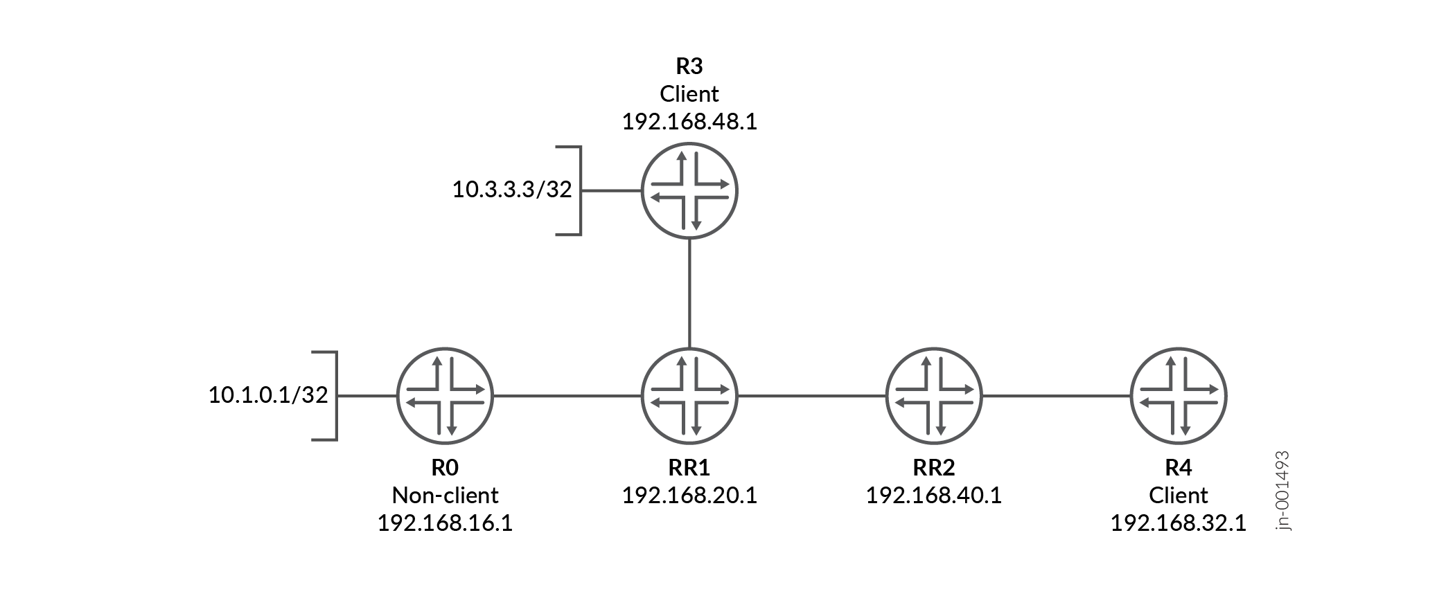
この例では、デバイスRR1がデバイスR3とデバイスRR2の両方のルートリフレクタになっています。ルートリフレクタRR1には、RR1-R3の10.13.1.3とRR1-RR2の10.12.1.2という2種類のクラスターIDが割り当てられています。
デバイスRR2は、デバイスR4のルートリフレクタです。
図 5を見てください。
この例では、デバイスRR1とデバイスRR2でのBGP設定を示しています。
設定
前提条件
複数のクラスターでBGPルートリフレクタを設定する前に、すべてのBGPピア間にIP到達可能性が存在することを確認します。この例では、OSPFやIS-ISなどの内部ゲートウェイプロトコル(IGP)が、IBGPセッションに使用されるループバックインターフェイス間の到達性を提供します。インターフェイスとIGPの設定は、設定されていると想定されており、ここでは示されていません。
手順
CLIクイックコンフィグレーション
この例をすばやく設定するには、以下のコマンドをコピーしてテキストファイルに貼り付け、改行を削除して、ネットワーク構成に合わせて必要な詳細を変更してから、コマンドを [edit] 階層レベルのCLIにコピー&ペーストします。
デバイスRR1
set protocols bgp group RR1_client type internal
set protocols bgp group RR1_client local-address 192.168.20.1
set protocols bgp group RR1_client cluster 10.13.1.3
set protocols bgp group RR1_client neighbor 192.168.48.1
set protocols bgp group Non_client type internal
set protocols bgp group Non_client local-address 192.168.20.1
set protocols bgp group Non_client neighbor 192.168.16.1
set protocols bgp group RR1_to_RR2 type internal
set protocols bgp group RR1_to_RR2 local-address 192.168.20.1
set protocols bgp group RR1_to_RR2 cluster 10.12.1.2
set protocols bgp group RR1_to_RR2 neighbor 192.168.40.1
デバイスRR2
set protocols bgp group RR2_client type internal
set protocols bgp group RR2_client local-address 192.168.40.1
set protocols bgp group RR2_client cluster 10.24.2.4
set protocols bgp group RR2_client neighbor 192.168.32.1
set protocols bgp group RR2_to_RR1 type internal
set protocols bgp group RR2_to_RR1 local-address 192.168.40.1
set protocols bgp group RR2_to_RR1 neighbor 192.168.20.1
デバイスRR1の設定
ステップバイステップの手順
次の例では、設定階層のさまざまなレベルに移動する必要があります。CLIのナビゲーションについては、『Junos OS CLIユーザーガイド』の「設定モードでのCLIエディタの使用」を参照してください。
デバイスRR1を設定するには:
-
デバイスR3とのピアリング関係を設定します。
[edit protocols bgp group RR1_client]
user@RR1# set type internal
user@RR1# set local-address 192.168.20.1
user@RR1# set cluster 10.13.1.3
user@RR1# set neighbor 192.168.48.1
-
デバイスR0とのピアリング関係を設定します。
[edit protocols bgp group Non_client]
user@RR1# set type internal
user@RR1# set local-address 192.168.20.1
user@RR1# set neighbor 192.168.16.1
-
デバイスRR2とのピアリング関係を設定します。
[edit protocols bgp group RR1_to_RR2]
user@RR1# set type internal
user@RR1# set local-address 192.168.20.1
user@RR1# set cluster 10.12.1.2
user@RR1# set neighbor 192.168.40.1
結果
設定モードから、 show protocols コマンドを入力して設定を確認します。出力に意図した設定が表示されない場合は、この例の手順を繰り返して設定を修正します。
user@RR1# show protocols
bgp {
    group RR1_client {
        type internal;
        local-address 192.168.20.1;
        cluster 10.13.1.3;
        neighbor 192.168.48.1;
    }
    group Non_client {
        type internal;
        local-address 192.168.20.1;
        neighbor 192.168.16.1;
    }
    group RR1_to_RR2 {
        type internal;
        local-address 192.168.20.1;
        cluster 10.12.1.2;
        neighbor 192.168.40.1;
    }
}
デバイスの設定が完了したら、設定モードから commit を入力します。
デバイスRR2の設定
ステップバイステップの手順
次の例では、設定階層のさまざまなレベルに移動する必要があります。CLIのナビゲーションについては、『Junos OS CLIユーザーガイド』の「設定モードでのCLIエディタの使用」を参照してください。
デバイスRR2を設定するには:
-
デバイスR4とのピアリング関係を設定します。
[edit protocols bgp group RR2_client]
user@RR2# set type internal
user@RR2# set local-address 192.168.40.1
user@RR2# set cluster 10.24.2.4
user@RR2# set neighbor 192.168.32.1
-
デバイスRR1とのピアリング関係を設定します。
[edit protocols bgp group RR2_to_RR1]
user@RR2# set type internal
user@RR2# set local-address 192.168.40.1
user@RR2# set neighbor 192.168.20.1
結果
設定モードから、 show protocols コマンドを入力して設定を確認します。出力に意図した設定が表示されない場合は、この例の手順を繰り返して設定を修正します。
user@RR2# show protocols
bgp {
    group RR2_client {
        type internal;
        local-address 192.168.40.1;
        cluster 10.24.2.4;
        neighbor 192.168.32.1;
    }
    group RR2_to_RR1 {
        type internal;
        local-address 192.168.40.1;
        neighbor 192.168.20.1;
    }
}
デバイスの設定が完了したら、設定モードから commit を入力します。
検証
設定が正常に機能していることを確認します。
ルート10.3.3.3にアドバタイズされたクラスタIDの確認
目的
設定されたインターフェイスで BGP が動作し、各ネイバーアドレスに対して BGP セッションが確立されていることを確認します。
アクション
動作モードから、 show route advertising-protocol bgp neighbor-address コマンドを入力します。
user@RR1> show route advertising-protocol bgp 192.168.40.1 active-path 10.3.3.3 extensive

inet.0: 61 destinations, 61 routes (60 active, 0 holddown, 1 hidden)
* 10.3.3.3/32 (1 entry, 1 announced)
 BGP group RR1_to_RR2 type Internal
     Nexthop: 192.168.48.1
     Localpref: 100
     AS path: [100] I
     Cluster ID: 10.13.1.3
     Originator ID: 192.168.48.1
意味
10.3.3.3/32のルートは、デバイスRR1のクライアント・ピアであるデバイスR3を起点としています。このルートをRR1のクライアントであるデバイスRR2に送信すると、ルートにはRR1-R3のクラスターIDである10.13.1.3クラスターIDが付加されます。
ルート10.1.0.1にアドバタイズされたクラスタIDの確認
目的
デバイスRR1からデバイスRR2へのルートアドバタイズを確認してください。
アクション
動作モードから、 show route advertising-protocol bgp neighbor-address コマンドを入力します。
user@RR1> show route advertising-protocol bgp 192.168.40.1 active-path 10.1.0.1/32 extensive
inet.0: 61 destinations, 61 routes (60 active, 0 holddown, 1 hidden)
* 10.1.0.1/32 (1 entry, 1 announced)
 BGP group RR1_to_RR2 type Internal
     Nexthop: 192.168.16.1
     Localpref: 100
     AS path: [100] I
     Cluster ID: 10.12.1.2
     Originator ID: 192.168.16.1
意味
10.1.0.1/32ルートは、デバイスRR1の非クライアントピアであるデバイスR0を起点としています。このルートをRR1のクライアントであるデバイスRR2に送信すると、ルートにはRR1-RR2のクラスターIDである10.12.1.2クラスターIDが付加されます。
デバイスRR1は、異なるクラスター内の別のクライアント(デバイスR4)にアドバタイズする際、デバイスRR2からの受信クラスターIDを保持します。
ASボーダールーターでのルートリフレクション
ほとんどの導入環境では、BGPルートリフレクタは内部BGP(IBGP)ルーターとしてのみ動作します。ただし、一部のネットワーク設計では、ルートリフレクタが自律システム境界ルーター(ASBR)として機能し、外部BGP(EBGP)ピアリングセッションを維持することもあります。
Junos OSルーターが両方の役割を果たし、EBGPピアからルートを受信する場合、 cluster オプションを使用してルートリフレクタクライアントとして設定されたIBGPピアにそのルートをルーターアドバタイズする場合は、特別な考慮事項が適用されます。この場合、Junos OSはIBGPクライアントにルートを反映する際に、ORIGINATOR_IDとCLUSTER_LISTパス属性をアタッチします。
BGPルートリフレクションを定義するRFC 4456は、EBGPを介して学習し、その後、デュアルロールASBRとルートリフレクタによってIBGPクライアントに反映されるルートに期待される動作を明示的に指定していません。Junos OS は、ルーティングループを防ぎ、自律システム内で決定論的なパス選択を維持するために、このシナリオでルートリフレクション属性を一貫して適用します。
ASボーダールーターにルートリフレクションを展開する場合は、ルーティングポリシー、パス選択、障害シナリオを慎重に検討し、反映されたルートによって意図しないルーティング動作が発生しないようにしてください。
変更履歴テーブル
サポートされる機能は、使用しているプラットフォームとリリースによって決まります。 機能エクスプローラー を使用して、機能がお使いのプラットフォームでサポートされているかどうかを確認します。
no-install ステートメントは、カーネルや分散型ファイアウォールデーモン(dfd)などのJunosシステムのルーティングプロトコルデーモン(rpd)と、ルーティングプロトコルデーモン(rpd)との間の相互作用を排除します。