BGPセッションのための自律システム
BGPローカルAS属性を理解する
インターネットサービスプロバイダ(ISP)が、異なる自律システム(AS)に属するネットワークを取得した場合、取得したネットワークのBGPピアを取得しているISPのASに移動するためのシームレスな方法はありません。新しいAS番号でBGPピアを設定するプロセスは、時間と面倒な作業がかかる場合があります。お客様がピアの配置や設定をすぐに変更したくない、または変更できない場合があります。このような移行期間中は、BGPの更新で以前のAS番号を使用するように、新しいASでBGP対応デバイスを設定すると便利です。この以前の AS 番号は ローカル AS と呼ばれます。
ローカルAS番号を使用することで、取得されたネットワーク内のルーティングデバイスが以前のASに属するように見えるようになります。
たとえば、AS が 65200 の ISP A は、AS が 65250 の ISP B を取得します。ISP Bには、設定を変更したくない顧客ISP Cがいます。ISP BがISP Aの一部になった後、ISP CとのEBGPピアセッションで使用するためにローカルAS番号65250が設定されます。その結果、ISP Cの直接外部ピアにルートをエクスポートするために使用されるASパスでは、ローカルAS番号の65250が、グローバルAS番号の65200の代わりに、先頭に追加されるか、使用されます。
内部BGP(IBGP)ピアからルートを受信した場合、ASパスにはグローバルAS番号の前の先頭にローカルAS番号が含まれます。
ルートが静的ルートやBGPにインポートされた内部ゲートウェイプロトコル(IGP)ルートなどの外部ルートである場合は、グローバルAS番号の代わりにローカルAS番号が使用されます。ルートが外部で、グローバルAS番号をASパスに含めるようにする場合は、 as-path-expand または as-path-prependを使用するルーティングポリシーを適用できます。 as-path-expand ポリシーアクションを使用して、グローバルAS番号をローカルAS番号の背後に配置します。 as-path-prepend ポリシーアクションを使用して、グローバルAS番号をローカルAS番号の前に配置します。
次に例を示します。
user@R2# show policy-options
policy-statement prepend-global {
    term 1 {
        from protocol static;
        then {
            as-path-prepend 65200; # or use as-path-expand
            accept;
        }
    }
}
user@R2# show protocols bgp
group ext {
    export prepend-global;
    type external;
    local-as 65250;
    neighbor 10.0.0.1 {
        peer-as 65100;
    }
    neighbor 10.1.0.2 {
        peer-as 65300;
    }
}
user@R2# show routing-options
static {
    route 10.1.1.1/32 next-hop 10.0.0.1;
}
autonomous-system 65200;
user@R3# run show route 10.1.1.1 protocol bgp
inet.0: 6 destinations, 6 routes (6 active, 0 holddown, 0 hidden)
+ = Active Route, - = Last Active, * = Both

10.1.1.1/32         *[BGP/170] 00:05:11, localpref 100
                      AS path: 65200 65250 I, validation-state: unverified
                    > to 10.1.0.1 via lt-1/2/0.4
プロバイダエッジ(PE)デバイスが外部BGP(EBGP)を使用してカスタマーエッジ(CE)デバイスとピアリングするレイヤー3 VPNシナリオでは、 local-as ステートメントの動作は非VPNシナリオとは異なります。VPNのシナリオでは、マスターインスタンスで定義されているグローバルAS番号は、デフォルトでASパスの先頭に付加されます。この動作を上書きするには、次に示すように、PE デバイスのルーティングインスタンスBGP設定で no-prepend-global-as を設定します。
user@R2# show routing-instances
red {
    instance-type vrf;
    interface fe-1/2/0.2;
    route-distinguisher 10:1;
    vrf-target target:10:1;
    protocols {
        bgp {
            group toR1 {
                type external;
                peer-as 65001;
                local-as 65200 no-prepend-global-as;
                neighbor 10.1.1.1;
            }
        }
    }
}
ローカルAS属性のJunosオペレーティングシステム(Junos OS)実装では、以下のオプションがサポートされています。
-
Local AS with private option—
privateオプションを使用すると、EBGPネイバーとのBGPセッション確立時にローカルASが使用されますが、他のIBGPおよびEBGPピアに送信されたASパスでは非表示になります。グローバルASのみが外部ピアに送信されるASパスに含まれます。privateオプションは、以前のASで設定されたままのルーティングデバイスとローカルピアリングを確立する場合や、ピアの配置をまだ変更していない特定の顧客とローカルピアを確立する場合に便利です。ローカル AS は、EBGP ネイバーとの BGP セッションを確立するために使用されますが、別の AS 内の外部ピアに送信された AS パスでは表示されません。外部ピアに送信されるASパスで、ローカルASがグローバルASの前の先頭に付加されないように、
privateオプションを含めます。privateオプションを指定すると、ローカルASはEBGPネイバーに送信されたASパスの先頭にのみ付加されます。例えば、 図1では、ルーター1 とルーター2 はAS 64496、ルーター4 はAS 64511、ルーター3 はAS 64510にあります。ルーター2は、以前はAS 64497に属していましたが、別のネットワークとマージされ、現在はAS 64496に属しています。ルーター3は以前のAS(64497)を使用してルーター2とまだピア関係にあるため、ルーター3とのピアリングを維持するには、ルーター2 を64497のローカルASで設定する必要があります。ローカル AS を 64497 に設定すると、ルーター 2 はルーター 3 へのルートをアドバタイズするときに AS 64497 を追加できます。ルーター3 は、プレフィックス 10/8の64497 64496のAS パスを確認します。
図1:ローカルAS構成
ルーター2が他のピアへの通知にローカルAS番号を追加しないようにするには、
local-as 64497 privateステートメントを使用します。このステートメントでは、ルーター1とルーター4 へルートを通知するときにローカルAS 64497を含まないよう、ルーター2 を設定します。この場合、ルーター4 は、プレフィックス 10.222/16のASパス 64496 64510を確認します。 -
Local AS with alias option—Junos OSリリース9.5以降では、ローカルASをエイリアスとして設定できます。BGPオープンセッションの確立中、オープンメッセージで使用されるASは、ローカルASとグローバルASが交互に入れ替わります。ローカルASをEBGPネイバーとの接続に使用する場合、BGPピアセッションの確立時にローカルASのみがASパスの先頭に追加されます。グローバルASがEBGPネイバーとの接続に使用される場合、BGPピアセッションが確立されると、グローバルASのみがASパスの先頭に追加されます。
aliasオプションを使用すると、EBGPネイバーから学習したルートに対して、ローカルASがASパスの先頭に付加されないことも意味します。そのため、ローカルASは他の外部ピアから非表示のままです。aliasオプションでローカルASを設定すると、取得したネットワーク内のルーティングデバイスを新しいASに移行する場合に特に便利です。移行プロセス中に、一部のルーティングデバイスは新しいASで設定されることがありますが、他のルーティングデバイスは以前のASで設定されたままになります。例えば、ルートリフレクタとして機能するルーティングデバイスを最初に新しいASに移行することから始めることをお勧めします。ただし、ルートリフレクタクライアントを段階的に移行すると、各ルートリフレクタは、以前のASで設定されたルーティングデバイスとピアリングし、新しいASで設定されたルーティングデバイスとピアリングする必要があります。ローカルピアセッションを確立するには、ネットワーク内のBGPピアがローカルASとグローバルASの両方を使用することが便利です。同時に、別のASにルートをエクスポートする際に、このローカルASを外部ピアから非表示にして、ASパスでグローバルASのみを使用します。このような状況では、aliasオプションを設定します。[edit routing-options]階層レベルで設定されたグローバルASのエイリアスとしてローカルASを設定するためのaliasオプションを含めます。ローカルASをエイリアスとして設定する場合、BGPオープンセッションの確立中に、オープンメッセージで使用されるASは、ローカルASとグローバルASが交互に入れ替わります。ローカルASは、EBGPネイバーとのピアセッションがそのローカルASを使用して確立された場合にのみ、ASパスの先頭に追加されます。ローカルASは、他のすべての外部ピアに送信されるASパスで非表示になっています。グローバルASを使用してBGPセッションを確立する場合、グローバルASのみがASパスの先頭に追加されます。注:privateオプションとaliasオプションは相互に排他的です。同じlocal-asステートメントで両方のオプションを設定することはできません。 -
Local AS with option not to prepend the global AS—Junos OS リリース9.6以降では、グローバルASを先頭に付加しないオプションでローカルASを設定することができます。ローカルASのみが外部ピアに送信されるASパスに含まれます。
仮想プライベートネットワーク(VPN)シナリオで、アウトバウンドBGPアップデートからグローバルAS番号を削除する場合は、
no-prepend-global-asオプションを使用します。このオプションは、VPNからグローバルASを非表示にするaVPNシナリオで便利です。外部ピアに送信されるASパスから削除された
[edit routing-options]階層レベルで設定されたグローバルASをno-prepend-global-asオプションを含めます。このオプションを使用すると、ローカルASのみがカスタマーエッジ(CE)デバイスに送信されたルートのASパスに含まれます。 -
Number of loops option—ローカルAS機能は、AS_PATH属性のAS番号を検出することでルートを破棄または非表示にする回数を指定する回数の指定もサポートしています。例えば、
loops 1を設定すると、AS番号がパス内で1回以上検知されると、ルートは非表示になります。これはデフォルトの動作です。loops 2を設定すると、AS番号がパス内で2回以上検知されると、ルートは非表示になります。loops numberステートメントでは、1 から 10 までを設定できます。注:任意のBGPグループにローカルAS値を設定すると、すべてのBGPグループのASとローカルAS値の両方を使用して、ルーティングループの検出が実行されます。
EBGPまたはIBGPピアのローカルASが現在のASと同じ場合は、
local-asステートメントを使用してローカルAS番号を指定しないでください。VRF内でローカルASを設定すると、ASパスループ検知メカニズムに影響します。デバイスに設定されたすべての
local-asステートメントは、単一のASドメインの一部です。ASパスループ検出メカニズムは、ドメイン内に一致するASが存在するかどうかを探すことに基づいています。
関連項目
例:EBGPセッションのローカルASの設定
この例では、インバウンドとアウトバウンドの更新でグローバルASとローカルASの両方が使用されるように、BGPピアのローカル自律システム(AS)を設定する方法BGP説明します。
要件
この例を設定する前に、デバイスの初期化以外の特別な設定は必要ありません。
概要
ISPがマージして顧客の設定(特に、顧客がピア関係を確立するように設定されているAS)を保持したい場合に、 local-as ステートメントを使用します。 local-as ステートメントは、ISPのルーターが別のASに移動した場合でも、お客様のルーターにすでに設置されているAS番号をシミュレートします。
この例では、 local-as ステートメントを使用してローカルASを設定する方法を示しています。 local-as ステートメントは、グローバル、グループ、およびネイバー階層レベルでBGPでサポートされています。
local-asステートメントを設定する際には、AS番号を指定する必要があります。1から 4,294,967,295までの 数値をプレーン番号形式で指定できます。Junos OS Release 9.1以降では、RFC 4893で定義されている4バイトAS番号のBGPサポートを提供するように、AS番号の範囲が拡張されていますBGP 4オクテットAS番号空間のサポート。Junos OS Release 9.3以降では、ピリオド<16-bit high-order value in decimal>.<16-bit low-order value in decimal>で連結された2つの整数値のASドット表記形式を使用して、4バイトのAS番号を設定することもできます。たとえば、プレーン番号形式で65,546の4 バイトAS数は、ASドット表記形式では1.10と 表されます。0.0〜 65535.65535までの値を ASドット表記形式で指定できます。Junos OS は、引き続き 2 バイト AS 番号のサポートを継続します。2バイトAS番号の範囲は1〜65,535です(これは4バイト範囲のサブセットです)。
図2 は、サンプルトポロジーを示しています。
 を設定するためのトポロジー
この例では、デバイスR2は以前AS 250に属していましたが、現在はAS 200にあります。デバイスR1とデバイスR3は、新しいAS番号(AS 200)とではなく、AS 250とピアリングするように設定されています。デバイスR2には、 autonomous-system 200 ステートメントで設定された新しいAS番号が付いています。ピアリングセッションを機能させるために、 local-as 250 ステートメントをBGP設定に追加します。 local-as 250 が設定されているため、デバイスR2のBGPインバウンドおよびアウトバウンドの更新には、グローバルAS(200)とローカルAS(250)の両方が含まれます。
設定
CLIクイックコンフィグレーション
この例をすばやく設定するには、以下のコマンドをコピーしてテキストファイルに貼り付け、改行を削除して、ネットワーク構成に合わせて必要な詳細を変更してから、コマンドを [edit] 階層レベルのCLIにコピー&ペーストします。
デバイスR1
set interfaces fe-1/2/0 unit 1 family inet address 10.0.0.1/30
set interfaces lo0 unit 1 family inet address 192.168.0.1/32
set protocols bgp group ext type external
set protocols bgp group ext export send-direct
set protocols bgp group ext export send-static
set protocols bgp group ext peer-as 250
set protocols bgp group ext neighbor 10.0.0.2
set policy-options policy-statement send-direct term 1 from protocol direct
set policy-options policy-statement send-direct term 1 then accept
set policy-options policy-statement send-static term 1 from protocol static
set policy-options policy-statement send-static term 1 then accept
set routing-options static route 10.1.0.0/30 next-hop 10.0.0.2
set routing-options autonomous-system 100
デバイスR2
set interfaces fe-1/2/0 unit 2 family inet address 10.0.0.2/30
set interfaces fe-1/2/1 unit 3 family inet address 10.1.0.1/30
set interfaces lo0 unit 2 family inet address 192.168.0.2/32
set protocols bgp group ext type external
set protocols bgp group ext export send-direct
set protocols bgp group ext export send-static
set protocols bgp group ext local-as 250
set protocols bgp group ext neighbor 10.0.0.1 peer-as 100
set protocols bgp group ext neighbor 10.1.0.2 peer-as 300
set policy-options policy-statement send-direct term 1 from protocol direct
set policy-options policy-statement send-direct term 1 then accept
set policy-options policy-statement send-static term 1 from protocol static
set policy-options policy-statement send-static term 1 then accept
set routing-options autonomous-system 200
デバイスR3
set interfaces fe-1/2/0 unit 4 family inet address 10.1.0.2/30
set interfaces lo0 unit 3 family inet address 192.168.0.3/32
set protocols bgp group ext type external
set protocols bgp group ext export send-direct
set protocols bgp group ext export send-static
set protocols bgp group ext peer-as 250
set protocols bgp group ext neighbor 10.1.0.1
set policy-options policy-statement send-direct term 1 from protocol direct
set policy-options policy-statement send-direct term 1 then accept
set policy-options policy-statement send-static term 1 from protocol static
set policy-options policy-statement send-static term 1 then accept
set routing-options static route 10.0.0.0/30 next-hop 10.1.0.1
set routing-options autonomous-system 300
デバイスR1の設定
ステップバイステップの手順
次の例では、設定階層のさまざまなレベルに移動する必要があります。CLIのナビゲーションについては、『Junos OS CLIユーザーガイド』の「設定モードでのCLIエディタの使用」を参照してください。
デバイスR1を設定するには:
インターフェイスを設定します。
[edit interfaces]
user@R1# set fe-1/2/0 unit 1 family inet address 10.0.0.1/30
user@R1# set lo0 unit 1 family inet address 192.168.0.1/32
外部BGP(EBGP)を設定します。
[edit protocols bgp group ext]
user@R1# set type external
user@R1# set export send-direct
user@R1# set export send-static
user@R1# set peer-as 250
user@R1# set neighbor 10.0.0.2
ルーティングポリシーを設定します。
[edit policy-options]
user@R1# set policy-statement send-direct term 1 from protocol direct
user@R1# set policy-statement send-direct term 1 then accept
user@R1# set policy-statement send-static term 1 from protocol static
user@R1# set policy-statement send-static term 1 then accept
デバイスR2とデバイスR3の間のリモートネットワークへの静的ルートを設定します。
[edit routing-options]
user@R1# set static route 10.1.0.0/30 next-hop 10.0.0.2
グローバルAS番号を設定します。
[edit routing-options]
user@R1# set autonomous-system 100
結果
設定モードから、 show interfaces、 show policy-options、 show protocols、 show routing-options コマンドを入力して設定を確認します。出力に意図した設定が表示されない場合は、この例の手順を繰り返して設定を修正します。
user@R1# show interfaces
fe-1/2/0 {
    unit 1 {
        family inet {
            address 10.0.0.1/30;
        }
    }
}
lo0 {
    unit 1 {
        family inet {
            address 192.168.0.1/32;
        }
    }
}
user@R1# show policy-options
policy-statement send-direct {
    term 1 {
        from protocol direct;
        then accept;
    }
}
policy-statement send-static {
    term 1 {
        from protocol static;
        then accept;
    }
}
user@R1# show protocols
bgp {
    group ext {
        type external;
        export [ send-direct send-static ];
        peer-as 250;
        neighbor 10.0.0.2;
    }
}
user@R1# show routing-options
static {
    route 10.1.0.0/30 next-hop 10.0.0.2;
}
autonomous-system 100;
デバイスの設定が完了したら、設定モードから commit を入力します。
デバイスR2の設定
ステップバイステップの手順
次の例では、設定階層のさまざまなレベルに移動する必要があります。CLIのナビゲーションについては、『Junos OS CLIユーザーガイド』の「設定モードでのCLIエディタの使用」を参照してください。
デバイスR2を設定するには:
インターフェイスを設定します。
[edit interfaces]
user@R2# set fe-1/2/0 unit 2 family inet address 10.0.0.2/30
user@R2# set fe-1/2/1 unit 3 family inet address 10.1.0.1/30
user@R2# set lo0 unit 2 family inet address 192.168.0.2/32
EBGPを設定します。
[edit protocols bgp group ext]
user@R2# set type external
user@R2# set export send-direct
user@R2# set export send-static
user@R2# set neighbor 10.0.0.1 peer-as 100
user@R2# set neighbor 10.1.0.2 peer-as 300
ローカル自律システム(AS)番号を設定します。
[edit protocols bgp group ext]
user@R2# set local-as 250
グローバルAS番号を設定します。
[edit routing-options]
user@R2# set autonomous-system 200
ルーティングポリシーを設定します。
[edit policy-options]
user@R2# set policy-statement send-direct term 1 from protocol direct
user@R2# set policy-statement send-direct term 1 then accept
user@R2# set policy-statement send-static term 1 from protocol static
user@R2# set policy-statement send-static term 1 then accept
結果
設定モードから、 show interfaces、 show policy-options、 show protocols、 show routing-options コマンドを入力して設定を確認します。出力に意図した設定が表示されない場合は、この例の手順を繰り返して設定を修正します。
user@R2# show interfaces
fe-1/2/0 {
    unit 2 {
        family inet {
            address 10.0.0.2/30;
        }
    }
}
fe-1/2/1 {
    unit 3 {
        family inet {
            address 10.1.0.1/30;
        }
    }
}
lo0 {
    unit 2 {
        family inet {
            address 192.168.0.2/32;
        }
    }
}
user@R2# show policy-options
policy-statement send-direct {
    term 1 {
        from protocol direct;
        then accept;
    }
}
policy-statement send-static {
    term 1 {
        from protocol static;
        then accept;
    }
}
user@R2# show protocols
bgp {
    group ext {
        type external;
        export [ send-direct send-static ];
        local-as 250;
        neighbor 10.0.0.1 {
            peer-as 100;
        }
        neighbor 10.1.0.2 {
            peer-as 300;
        }
    }
}
user@R2# show routing-options
autonomous-system 200;
デバイスの設定が完了したら、設定モードから commit を入力します。
デバイスR3の設定
ステップバイステップの手順
次の例では、設定階層のさまざまなレベルに移動する必要があります。CLIのナビゲーションについては、『Junos OS CLIユーザーガイド』の「設定モードでのCLIエディタの使用」を参照してください。
デバイスR3を設定するには:
インターフェイスを設定します。
[edit interfaces]
user@R3# set fe-1/2/0 unit 4 family inet address 10.1.0.2/30
user@R3# set lo0 unit 3 family inet address 192.168.0.3/32
EBGPを設定します。
[edit protocols bgp group ext]
user@R3# set type external
user@R3# set export send-direct
user@R3# set export send-static
user@R3# set peer-as 250
user@R3# set neighbor 10.1.0.1
グローバル自律システム(AS)番号を設定します。
[edit routing-options]
user@R3# set autonomous-system 300
デバイスR1とデバイスR2の間でリモートネットワークへの静的ルートを設定します。
[edit routing-options]
user@R3# set static route 10.0.0.0/30 next-hop 10.1.0.1
ルーティングポリシーを設定します。
[edit policy-options]
user@R3# set policy-statement send-direct term 1 from protocol direct
user@R3# set policy-statement send-direct term 1 then accept
user@R3# set policy-statement send-static term 1 from protocol static
user@R3# set policy-statement send-static term 1 then accept
結果
設定モードから、 show interfaces、 show policy-options、 show protocols、 show routing-options コマンドを入力して設定を確認します。出力に意図した設定が表示されない場合は、この例の手順を繰り返して設定を修正します。
user@R3# show interfaces
fe-1/2/0 {
    unit 4 {
        family inet {
            address 10.1.0.2/30;
        }
    }
}
lo0 {
    unit 3 {
        family inet {
            address 192.168.0.3/32;
        }
    }
}
user@R3# show policy-options
policy-statement send-direct {
    term 1 {
        from protocol direct;
        then accept;
    }
}
policy-statement send-static {
    term 1 {
        from protocol static;
        then accept;
    }
}
user@R3# show protocols
bgp {
    group ext {
        type external;
        export [ send-direct send-static ];
        peer-as 250;
        neighbor 10.1.0.1;
    }
}
user@R3# show routing-options
static {
    route 10.0.0.0/30 next-hop 10.1.0.1;
}
autonomous-system 300;
デバイスの設定が完了したら、設定モードから commit を入力します。
検証
設定が正常に機能していることを確認します。
ローカルおよびグローバルAS設定の確認
目的
デバイスR2でローカルおよびグローバルのAS設定が行われていることを確認します。
アクション
動作モードから、 show bgp neighbors コマンドを入力します。
user@R2> show bgp neighbors
Peer: 10.0.0.1+179 AS 100      Local: 10.0.0.2+61036 AS 250
  Type: External    State: Established    Flags: <Sync>
  Last State: OpenConfirm   Last Event: RecvKeepAlive
  Last Error: None
  Export: [ send-direct send-static ]
  Options: <Preference PeerAS LocalAS Refresh>
  Holdtime: 90 Preference: 170 Local AS: 250 Local System AS: 200
  Number of flaps: 0
  Peer ID: 192.168.0.1     Local ID: 192.168.0.2       Active Holdtime: 90
  Keepalive Interval: 30         Peer index: 0
  BFD: disabled, down
  Local Interface: fe-1/2/0.2
  NLRI for restart configured on peer: inet-unicast
  NLRI advertised by peer: inet-unicast
  NLRI for this session: inet-unicast
  Peer supports Refresh capability (2)
  Stale routes from peer are kept for: 300
  Peer does not support Restarter functionality
  NLRI that restart is negotiated for: inet-unicast
  NLRI of received end-of-rib markers: inet-unicast
  NLRI of all end-of-rib markers sent: inet-unicast
  Peer supports 4 byte AS extension (peer-as 100)
  Peer does not support Addpath
  Table inet.0 Bit: 10000
    RIB State: BGP restart is complete
    Send state: in sync
    Active prefixes:              1
    Received prefixes:            3
    Accepted prefixes:            2
    Suppressed due to damping:    0
    Advertised prefixes:          4
  Last traffic (seconds): Received 6    Sent 14   Checked 47
  Input messages:  Total 258    Updates 3       Refreshes 0     Octets 4969
  Output messages: Total 258    Updates 2       Refreshes 0     Octets 5037
  Output Queue[0]: 0

Peer: 10.1.0.2+179 AS 300      Local: 10.1.0.1+52296 AS 250
  Type: External    State: Established    Flags: <Sync>
  Last State: OpenConfirm   Last Event: RecvKeepAlive
  Last Error: None
  Export: [ send-direct send-static ]
  Options: <Preference PeerAS LocalAS Refresh>
  Holdtime: 90 Preference: 170 Local AS: 250 Local System AS: 200
  Number of flaps: 0
  Peer ID: 192.168.0.3     Local ID: 192.168.0.2       Active Holdtime: 90
  Keepalive Interval: 30         Peer index: 1
  BFD: disabled, down
  Local Interface: fe-1/2/1.3
  NLRI for restart configured on peer: inet-unicast
  NLRI advertised by peer: inet-unicast
  NLRI for this session: inet-unicast
  Peer supports Refresh capability (2)
  Stale routes from peer are kept for: 300
  Peer does not support Restarter functionality
  NLRI that restart is negotiated for: inet-unicast
  NLRI of received end-of-rib markers: inet-unicast
  NLRI of all end-of-rib markers sent: inet-unicast
  Peer supports 4 byte AS extension (peer-as 300)
  Peer does not support Addpath
  Table inet.0 Bit: 10000
    RIB State: BGP restart is complete
    Send state: in sync
    Active prefixes:              1
    Received prefixes:            3
    Accepted prefixes:            2
    Suppressed due to damping:    0
    Advertised prefixes:          4
  Last traffic (seconds): Received 19   Sent 26   Checked 9
  Input messages:  Total 256    Updates 3       Refreshes 0     Octets 4931
  Output messages: Total 256    Updates 2       Refreshes 0     Octets 4999
  Output Queue[0]: 0
意味
ローカル AS: 250 とローカル システム AS: 200 の出力は、デバイス R2 に予期された設定であることを示しています。さらに、出力は、オプションリストにLocalASが含まれていることを示しています。
BGPピアリングセッションの確認
目的
セッションが確立されていること、およびローカルAS番号250が表示されていることを確認します。
アクション
動作モードから、 show bgp summary コマンドを入力します。
user@R1> show bgp summary
Groups: 1 Peers: 1 Down peers: 0
Table          Tot Paths  Act Paths Suppressed    History Damp State    Pending
inet.0                 4          2          0          0          0          0
Peer                     AS      InPkt     OutPkt    OutQ   Flaps Last Up/Dwn State|#Active/Received/Accepted/Damped...
10.0.0.2                250        232        233       0       4     1:42:37 2/4/4/0              0/0/0/0
user@R3> show bgp summary
Groups: 1 Peers: 1 Down peers: 0
Table          Tot Paths  Act Paths Suppressed    History Damp State    Pending
inet.0                 4          2          0          0          0          0
Peer                     AS      InPkt     OutPkt    OutQ   Flaps Last Up/Dwn State|#Active/Received/Accepted/Damped...
10.1.0.1                250        235        236       0       4     1:44:25 2/4/4/0              0/0/0/0
意味
デバイスR2が実際にはAS 200にあっても、デバイスR1とデバイスR3はAS 250内のデバイスとピアリングしているように見えます。
BGP ASパスの検証
目的
ルーティングテーブルにルートがあり、ASパスにローカルAS番号250が表示されていることを確認します。
アクション
設定モードから、 set route protocol bgp コマンドを入力します。
user@R1> show route protocol bgp
inet.0: 6 destinations, 8 routes (6 active, 0 holddown, 0 hidden)
+ = Active Route, - = Last Active, * = Both

10.0.0.0/30         [BGP/170] 01:46:44, localpref 100
                      AS path: 250 I
                    > to 10.0.0.2 via fe-1/2/0.1
10.1.0.0/30         [BGP/170] 01:46:44, localpref 100
                      AS path: 250 I
                    > to 10.0.0.2 via fe-1/2/0.1
192.168.0.2/32     *[BGP/170] 01:46:44, localpref 100
                      AS path: 250 I
                    > to 10.0.0.2 via fe-1/2/0.1
192.168.0.3/32     *[BGP/170] 01:46:40, localpref 100
                      AS path: 250 300 I
                    > to 10.0.0.2 via fe-1/2/0.1
user@R3> show route protocol bgp

inet.0: 6 destinations, 8 routes (6 active, 0 holddown, 0 hidden)
+ = Active Route, - = Last Active, * = Both

10.0.0.0/30         [BGP/170] 01:47:10, localpref 100
                      AS path: 250 I
                    > to 10.1.0.1 via fe-1/2/0.4
10.1.0.0/30         [BGP/170] 01:47:10, localpref 100
                      AS path: 250 I
                    > to 10.1.0.1 via fe-1/2/0.4
192.168.0.1/32     *[BGP/170] 01:47:10, localpref 100
                      AS path: 250 100 I
                    > to 10.1.0.1 via fe-1/2/0.4
192.168.0.2/32     *[BGP/170] 01:47:10, localpref 100
                      AS path: 250 I
                    > to 10.1.0.1 via fe-1/2/0.4
意味
出力では、デバイスR2が実際にはAS 200にあっても、デバイスR1とデバイスR3にはAS 250を含むASパスを持つルートがあるように見えることが示されています。
例:EBGPセッション用のプライベートローカルASの設定
この例では、プライベートローカル自律システム(AS)番号を設定する方法を示しています。ローカルASは、ピアリングにローカルAS番号を使用するピアにアドバタイズされるため、プライベートと見なされますが、ピアリングにグローバルAS番号を使用できるピアへの通知では表示されません。
要件
この例を設定する前に、デバイスの初期化以外の特別な設定は必要ありません。
概要
ISPがマージして顧客の設定(特に、顧客がピア関係を確立するように設定されているAS)を保持したい場合に、 local-as ステートメントを使用します。 local-as ステートメントは、ISPのルーターが別のASに移動した場合でも、お客様のルーターにすでに設置されているAS番号をシミュレートします。
privateオプションを使用すると、ローカルASは、外部BGP(EBGP)ネイバーとのBGPセッション確立時に使用されますが、他のEBGPピアに送信されるASパスでは非表示になります。グローバルASのみが外部ピアに送信されるASパスに含まれます。
privateオプションは、以前のASで設定されたままのルーティングデバイスとローカルピアリングを確立する場合や、ピアの配置をまだ変更していない特定の顧客とローカルピアを確立する場合に便利です。ローカルASは、EBGPネイバーとのBGPセッションを確立するために使用されますが、別のASの外部ピアに送信されたASパスでは非表示になっています。
外部ピアに送信されるASパスで、ローカルASがグローバルASの前の先頭に付加されないように、 private オプションを含めます。 private オプションを指定すると、EBGPネイバーに送信されたASパスの先頭にのみローカルASが付加されます。
図3は、サンプルトポロジーを示しています。
 を設定するためのトポロジー
デバイスR1はAS 64496にあります。デバイスR2はAS 64510にあります。デバイスR3はAS 64511にあります。デバイスR4はAS 64512にあります。デバイスR1は、以前はAS 64497に属していましたが、別のネットワークとマージされ、現在はAS 64496に属しています。デバイスR3は以前のASである64497を使用してデバイスR1とまだピア関係にあるため、デバイスR3とのピアリングを維持するには、デバイスR1を64497のローカルASで設定する必要があります。64497のローカルASを設定すると、デバイスR3へのルートをアドバタイズするときに、デバイスR1がAS 64497を追加できるようになります。デバイスR3は、プレフィックス10.1.1.2/32の64497 64496のASパスを確認します。これは、デバイスR2のループバックインターフェイスです。デバイスR4は、デバイスR3の後ろにあり、デバイスR2のループバックインターフェイスへの64511 64497 64496 64510のASパスを確認します。デバイスR1が他のピアへの通知にローカルAS番号を追加しないようにするために、この例では local-as 64497 private ステートメントを含めています。 private オプションは、デバイスR2へのルートを通知するときにローカルAS 64497を含まないデバイスR1を設定します。デバイスR2は、デバイスR3への64496 64511のASパスとデバイスR4への64496 64511 64512のASパスを確認します。デバイスR1の設定で private オプションを選択すると、デバイスR1がデバイスR2に再アドバタイズするASパスからAS番号64497がなくなります。
デバイスR1は、デバイスR3を除くすべてのルーターからプライベートローカルASを非表示にしています。 private オプションは、デバイスR1がデバイスR3から受信(学習)し、デバイスR1が他のルーターに再アドバタイズするルートに適用されます。デバイスR3から学習したこれらのルートがデバイスR1からデバイスR2に再アドバタイズされると、デバイスR2にアドバタイズされたASパスからプライベートローカルASがなくなります。
設定
CLIクイックコンフィグレーション
この例をすばやく設定するには、以下のコマンドをコピーしてテキスト ファイルに貼り付け、改行を削除して、ネットワーク構成に合わせて必要な詳細を変更し、 [edit] 階層レベルのCLIにコマンドをコピー アンド ペーストします。
デバイスR1
set interfaces fe-1/2/0 unit 3 family inet address 192.168.1.1/24
set interfaces fe-1/2/1 unit 5 family inet address 192.168.10.1/24
set interfaces lo0 unit 2 family inet address 10.1.1.1/32
set protocols bgp group external-AS64511 type external
set protocols bgp group external-AS64511 peer-as 64511
set protocols bgp group external-AS64511 local-as 64497
set protocols bgp group external-AS64511 local-as private
set protocols bgp group external-AS64511 neighbor 192.168.1.2
set protocols bgp group external-AS64510 type external
set protocols bgp group external-AS64510 peer-as 64510
set protocols bgp group external-AS64510 neighbor 192.168.10.2
set policy-options policy-statement send-direct term 1 from protocol direct
set policy-options policy-statement send-direct term 1 then accept
set routing-options autonomous-system 64496
デバイスR2
set interfaces fe-1/2/0 unit 6 family inet address 192.168.10.2/24
set interfaces lo0 unit 3 family inet address 10.1.1.2/32
set protocols bgp group external type external
set protocols bgp group external export send-direct
set protocols bgp group external peer-as 64496
set protocols bgp group external neighbor 192.168.10.1
set policy-options policy-statement send-direct term 1 from protocol direct
set policy-options policy-statement send-direct term 1 then accept
set routing-options autonomous-system 64510
デバイスR3
set interfaces fe-1/2/0 unit 4 family inet address 192.168.1.2/24
set interfaces fe-1/2/1 unit 7 family inet address 192.168.5.1/24
set interfaces lo0 unit 4 family inet address 10.1.1.3/32
set protocols bgp group external type external
set protocols bgp group external export send-direct
set protocols bgp group external neighbor 192.168.1.1 peer-as 64497
set protocols bgp group external neighbor 192.168.5.2 peer-as 64512
set policy-options policy-statement send-direct term 1 from protocol direct
set policy-options policy-statement send-direct term 1 then accept
set routing-options autonomous-system 64511
デバイスR4
set interfaces fe-1/2/0 unit 8 family inet address 192.168.5.2/24
set interfaces lo0 unit 5 family inet address 10.1.1.4/32
set protocols bgp group external type external
set protocols bgp group external export send-direct
set protocols bgp group external peer-as 64511
set protocols bgp group external neighbor 192.168.5.1
set policy-options policy-statement send-direct term 1 from protocol direct
set policy-options policy-statement send-direct term 1 then accept
set routing-options autonomous-system 64512
デバイスR1の設定
ステップバイステップの手順
次の例では、設定階層のさまざまなレベルに移動する必要があります。CLIのナビゲーションについては、『Junos OS CLIユーザーガイド』の「設定モードでのCLIエディターの使用」を参照してください。
デバイスR1を設定するには:
-
インターフェイスを設定します。
[edit interfaces fe-1/2/0 unit 3]
user@R1# set family inet address 192.168.1.1/24
[edit interfaces fe-1/2/1 unit 5]
user@R1# set family inet address 192.168.10.1/24
[edit interfaces lo0 unit 2]
user@R1# set family inet address 10.1.1.1/32
-
デバイスR2とのEBGPピアリングセッションを設定します。
[edit protocols bgp group external-AS64510]
user@R1# set type external
user@R1# set peer-as 64510
user@R1# set neighbor 192.168.10.2
-
デバイスR3とのEBGPピアリングセッションを設定します。
[edit protocols bgp group external-AS64511]
user@R1# set type external
user@R1# set peer-as 64511
user@R1# set local-as 64497
user@R1# set local-as private
user@R1# set neighbor 192.168.1.2
-
ルーティングポリシーを設定します。
[edit policy-options policy-statement send-direct term 1]
user@R1# set from protocol direct
user@R1# set then accept
-
グローバル自律システム(AS)番号を設定します。
[edit routing-options]
user@R1# set autonomous-system 64496
結果
設定モードから、 show interfaces、 show policy-options、 show protocols、および show routing-options コマンドを入力して設定を確認します。出力に意図した設定が表示されない場合は、この例の手順を繰り返して設定を修正します。
user@R1# show interfaces
fe-1/2/0 {
    unit 3 {
        family inet {
            address 192.168.1.1/24;
        }
    }
}
fe-1/2/1 {
    unit 5 {
        family inet {
            address 192.168.10.1/24;
        }
    }
}
lo0 {
    unit 2 {
        family inet {
            address 10.1.1.1/32;
        }
    }
}
user@R1# show policy-options
policy-statement send-direct {
    term 1 {
        from protocol direct;
        then accept;
    }
}
user@R1# show protocols
bgp {
    group external-AS64511 {
        type external;
        peer-as 64511;
        local-as 64497 private;
        neighbor 192.168.1.2;
    }
    group external-AS64510 {
        type external;
        peer-as 64510;
        neighbor 192.168.10.2;
    }
}
user@R1# show routing-options
autonomous-system 64496;
デバイスの設定が完了したら、設定モードから commit を入力します。
トポロジー内の他のデバイスに対して、必要に応じて設定を繰り返します。
検証
設定が正常に機能していることを確認します。
デバイスR2のASパスの確認
目的
デバイスR2がデバイスR3およびデバイスR4へのASパスにAS 64497が含まれていないことを確認します。
アクション
動作モードから、 show route protocol bgp コマンドを入力します。
user@R2> show route protocol bgp
inet.0: 6 destinations, 6 routes (6 active, 0 holddown, 0 hidden)
+ = Active Route, - = Last Active, * = Both

10.1.1.3/32        *[BGP/170] 01:33:11, localpref 100
                      AS path: 64496 64511 I
                    > to 192.168.10.1 via fe-1/2/0.6
10.1.1.4/32        *[BGP/170] 01:33:11, localpref 100
                      AS path: 64496 64511 64512 I
                    > to 192.168.10.1 via fe-1/2/0.6
192.168.5.0/24     *[BGP/170] 01:49:15, localpref 100
                      AS path: 64496 64511 I
                    > to 192.168.10.1 via fe-1/2/0.6
意味
デバイスR2のASパスに、AS 64497は含まれません。
デバイスR3のASパスの確認
目的
ローカル AS 64497 が、EBGP ネイバー R3 に送信された AS パスの先頭にのみ付加されていることを確認します。デバイスR3は、プレフィックス10.1.1.2/32の64497 64496のASパスを確認します。これは、デバイスR2のループバックインターフェイスです。
アクション
動作モードから、 show route protocol bgp コマンドを入力します。
user@R3> show route protocol bgp
inet.0: 7 destinations, 8 routes (7 active, 0 holddown, 0 hidden)
+ = Active Route, - = Last Active, * = Both

10.1.1.2/32        *[BGP/170] 01:35:11, localpref 100
                      AS path: 64497 64496 64510 I
                    > to 192.168.1.1 via fe-1/2/0.4
10.1.1.4/32        *[BGP/170] 01:35:11, localpref 100
                      AS path: 64512 I
                    > to 192.168.5.2 via fe-1/2/1.7
192.168.5.0/24      [BGP/170] 01:51:15, localpref 100
                      AS path: 64512 I
                    > to 192.168.5.2 via fe-1/2/1.7
意味
デバイスR2へのデバイスR3のルート(プレフィックス10.1.1.2)には、デバイスR1に設定されたローカルとグローバルの両方のASが含まれます(それぞれ64497と64496)。
BGPの累積IGP属性を理解する
内部ゲートウェイプロトコル(IGP)は、単一ドメインまたは自律システム(AS)内でルーティングを処理するように設計されています。各リンクには、メトリックと呼ばれる特定の値が割り当てられます。2 つのノード間の距離は、パスに沿ったリンクのすべてのメトリック値の合計として計算されます。IGPは、距離に基づいて2つのノード間の最短パスを選択します。
BGPは、多数の独立したAS上でルーティングを提供するように設計されており、それぞれの運用管理間の調整は制限されているか、一切ありません。BGPは、パス選択の決定にメトリックを使用しません。
BGPの累積IGP(AIGP)メトリック属性により、1つの管理で複数の連続したBGP ASを実行できる導入が可能になります。このような導入により、BGPはIGPメトリックに基づいてルーティングを決定できます。このようなネットワークでは、BGPはIGPのようにメトリックに基づいてパスを選択することができます。この場合、ノードは2つの異なるASにありますが、BGPは2つのノード間の最短パスを選択します。
AIGP属性は、トンネリングを使用してBGPネクストホップにパケットを配信するネットワークで特に役立ちます。ジュニパーネットワークス® Junos®オペレーティングシステム(Junos OS)は現在、 family inet labeled-unicast と family inet6 labeled-unicastの2つのBGPアドレスファミリーに対してAIGP属性をサポートしています。
AIGPは、BGP最適ルート決定プロセスに影響を与えます。AIGP属性優先ルールは、ローカル優先ルールの後に適用されます。AIGPの距離は、同点を破ることと比較されます。BGP最適ルートの決定プロセスは、解決ネクストホップにAIGP属性がある場合、内部コストルールの適用方法にも影響します。AIGP を有効にしていない場合、ルートの内部コストは、ルートのネクスト ホップへのメトリックの計算に基づきます。AIGP を有効にすると、解決中の AIGP 距離が内部コストに追加されます。
リリース20.2R1以降、Junos OSはAIGPメトリックからMEDへの変換をサポートしています。この機能は、最適なパスを選択するために使用されるエンドツーエンドのAIGPメトリック値をMEDに伝送させたい場合に有効にできます。これは、顧客サイトが 2 つの異なるサービスプロバイダを介して接続されており、顧客エッジルーターが IGP メトリックベースの決定を行う必要がある場合、AS 間 MPLS VPN ソリューションで特に役立ちます。effective-aigp が既知の最小値を超えて変化した場合に、ルートの不要な更新を防ぐ minimum-aigp を設定できます。有効なAIGPは、ネクストホップに到達するためのルートにIGPコストを加えたものを足したAIGP値です。 effective-aigp および minimum-effective-aigp ステートメントは、 [edit protocols bgp group <group-name> metric-out] および [edit policy-options policy-statement <name> then metric] 階層レベルで設定できます。
AIGP属性は、オプションの非推移的BGPパス属性であり、インターネットドラフトdraft-ietf-idr-aigp-06、 BGPの累積IGPメトリック属性で指定されています。
関連項目
例:BGPの累積IGP属性の設定
この例では、BGPの累積IGP(AIGP)メトリック属性を設定する方法を示します。
要件
この例では、以下のハードウェアおよびソフトウェアコンポーネントを使用しています。
-
BGP を話すデバイス 7 台。
-
Junos OS リリース 12.1 以降。
概要
AIGP属性は、単一の管理で複数の連続したBGP自律システム(AS)を実行できる導入を可能にします。このような導入により、BGPはIGPメトリックに基づいてルーティングを決定できます。AIGPを有効にすると、BGPはIGPメトリックに基づいてパスを選択できます。これにより、ノードが異なるASにあっても、BGPは2つのノード間の最短パスを選択できます。AIGP属性は、トンネリングを使用してBGPネクストホップにパケットを配信するネットワークで特に役立ちます。この例では、MPLSラベルスイッチパスで設定されたAIGPを示しています。
AIGPを有効にするには、プロトコルファミリーベースでBGP設定に aigp ステートメントを含めます。特定のファミリーでAIGPを設定することで、そのファミリーのAIGP属性の送受信が可能になります。デフォルトでは、AIGPは無効になっています。AIGP が無効になっているネイバーは、AIGP 属性を送信せず、受信した AIGP 属性をサイレントに破棄します。
Junos OSは、 family inet labeled-unicast と family inet6 labeled-unicast用のAIGPをサポートしています。 aigp ステートメントは、グローバルBGP、グループ、またはネイバーレベルで、特定のファミリーに対して設定できます。
デフォルトでは、ローカルプレフィックスのAIGP属性の値はゼロです。AIGP対応ネイバーは、 aigp-originate ポリシーアクションを使用して、エクスポートポリシーによって特定のプレフィックスに対してAIGP属性を発信できます。AIGP属性の値は、プレフィックスまでのIGP距離を反映しています。または、 aigp-originate distance distance ポリシーアクションを使用して値を指定することもできます。設定可能な範囲は 0 から 4,294,967,295 です。AIGP属性を発信する必要があるのは1つのノードだけです。ネイバーがBGP設定の aigp ステートメントでAIGPを有効にしている場合、AIGP属性は保持され、再アドバタイズされます。
AIGP属性を発生させるポリシーアクションには、以下の要件があります。
-
ネイバーはAIGPが有効である必要があります。
-
ポリシーは、エクスポートポリシーとして適用する必要があります。
-
プレフィックスには、現在のAIGP属性があってはなりません。
-
プレフィックスはネクストホップ自己でエクスポートする必要があります。
-
プレフィックスはAIGPドメイン内に存在する必要があります。通常、ループバックIPアドレスが発信元のプレフィックスとなります。
これらの要件が満たされない場合、ポリシーは無視されます。
トポロジー図
図4は、この例で使用されているトポロジーを示しています。OSPFは、内部ゲートウェイプロトコル(IGP)として使用されます。内部 BGP(IBGP)は、デバイス PE1 とデバイス PE4 の間で設定されます。外部 BGP(EBGP)は、デバイス PE7 とデバイス PE1 の間、デバイス PE4 とデバイス PE3 の間、およびデバイス PE4 とデバイス PE2 の間で設定されます。デバイス PE4、PE2、および PE3 はマルチホップ用に設定されています。デバイス PE4 は、AIGP 値に基づいてパスを選択し、AIGP とポリシー設定に基づいて AIGP 値を再度アドバタイズします。デバイスPE1は、別の管理ドメインにあるデバイスPE7にAIGP値を再アドバタイズします。すべてのデバイスには 2 つのループバック インターフェイス アドレスがあります。10.9.9.x は BGP ピアリングとルーター ID に使用され、10.100.1.x は BGP ネクストホップに使用されます。
デバイスPE1とPE3間のネットワークには、IBGPピアリングと複数のOSPFエリアがあります。デバイス PE7 への外部リンクは、AIGP 属性が AIGP 対応になっている場合、管理ドメイン外のネイバーに再アドバタイズされることを示すように設定されています。
 における複数パスのアドバタイズメント
AIGP属性を発信するには、BGPネクストホップがそれ自体である必要があります。BGPネクストホップが変更されない場合、受信したAIGP属性は、そのまま別のAIGPネイバーに再アドバタイズされます。ネクストホップが変更された場合、受信したAIGP属性は、別のAIGPネイバーに値を増やして再アドバタイズされます。値の増加は、前の BGP ネクスト ホップまでの IGP 距離を反映しています。デモンストレーションのために、この例では、デバイス PE4 とデバイス PE2 およびデバイス PE3 との EBGP ピアリング セッションにループバック インターフェイス アドレスを使用しています。これらのセッションではマルチホップが有効になっているため、再帰的ルックアップが実行され、ポイントツーポイントインターフェイスが決定されます。ネクストホップが変更されるため、AIGP距離にIGP距離が加算されます。
設定
CLIクイックコンフィグレーション
この例をすばやく設定するには、以下のコマンドをコピーしてテキストファイルに貼り付け、改行を削除して、ネットワーク構成に合わせて必要な詳細を変更してから、コマンドを [edit] 階層レベルのCLIにコピー&ペーストします。
デバイスP1
set interfaces fe-1/2/0 unit 1 description P1-to-PE1
set interfaces fe-1/2/0 unit 1 family inet address 10.0.0.2/30
set interfaces fe-1/2/0 unit 1 family mpls
set interfaces fe-1/2/1 unit 4 description P1-to-P2
set interfaces fe-1/2/1 unit 4 family inet address 10.0.0.29/30
set interfaces fe-1/2/1 unit 4 family mpls
set interfaces fe-1/2/2 unit 8 description P1-to-PE4
set interfaces fe-1/2/2 unit 8 family inet address 10.0.0.17/30
set interfaces fe-1/2/2 unit 8 family mpls
set interfaces lo0 unit 3 family inet address 10.9.9.2/32
set interfaces lo0 unit 3 family inet address 10.100.1.2/32
set protocols rsvp interface fe-1/2/0.1
set protocols rsvp interface fe-1/2/2.8
set protocols rsvp interface fe-1/2/1.4
set protocols mpls label-switched-path P1-to-P2 to 10.9.9.3
set protocols mpls label-switched-path P1-to-PE1 to 10.9.9.1
set protocols mpls label-switched-path P1-to-PE4 to 10.9.9.4
set protocols mpls interface fe-1/2/0.1
set protocols mpls interface fe-1/2/2.8
set protocols mpls interface fe-1/2/1.4
set protocols bgp group internal type internal
set protocols bgp group internal local-address 10.9.9.2
set protocols bgp group internal family inet labeled-unicast aigp
set protocols bgp group internal neighbor 10.9.9.1
set protocols bgp group internal neighbor 10.9.9.3
set protocols bgp group internal neighbor 10.9.9.4
set protocols ospf area 0.0.0.1 interface fe-1/2/0.1 metric 1
set protocols ospf area 0.0.0.1 interface fe-1/2/1.4 metric 1
set protocols ospf area 0.0.0.0 interface fe-1/2/2.8 metric 1
set protocols ospf area 0.0.0.0 interface 10.9.9.2 passive
set protocols ospf area 0.0.0.0 interface 10.9.9.2 metric 1
set protocols ospf area 0.0.0.0 interface 10.100.1.2 passive
set protocols ospf area 0.0.0.0 interface 10.100.1.2 metric 1
set routing-options router-id 10.9.9.2
set routing-options autonomous-system 13979
デバイスP2
set interfaces fe-1/2/0 unit 3 description P2-to-PE1
set interfaces fe-1/2/0 unit 3 family inet address 10.0.0.6/30
set interfaces fe-1/2/0 unit 3 family mpls
set interfaces fe-1/2/1 unit 5 description P2-to-P1
set interfaces fe-1/2/1 unit 5 family inet address 10.0.0.30/30
set interfaces fe-1/2/1 unit 5 family mpls
set interfaces fe-1/2/2 unit 6 description P2-to-PE4
set interfaces fe-1/2/2 unit 6 family inet address 10.0.0.13/30
set interfaces fe-1/2/2 unit 6 family mpls
set interfaces lo0 unit 5 family inet address 10.9.9.3/32
set interfaces lo0 unit 5 family inet address 10.100.1.3/32
set protocols rsvp interface fe-1/2/1.5
set protocols rsvp interface fe-1/2/2.6
set protocols rsvp interface fe-1/2/0.3
set protocols mpls label-switched-path P2-to-PE1 to 10.9.9.1
set protocols mpls label-switched-path P2-to-P1 to 10.9.9.2
set protocols mpls label-switched-path P2-to-PE4 to 10.9.9.4
set protocols mpls interface fe-1/2/1.5
set protocols mpls interface fe-1/2/2.6
set protocols mpls interface fe-1/2/0.3
set protocols bgp group internal type internal
set protocols bgp group internal local-address 10.9.9.3
set protocols bgp group internal family inet labeled-unicast aigp
set protocols bgp group internal neighbor 10.9.9.1
set protocols bgp group internal neighbor 10.9.9.2
set protocols bgp group internal neighbor 10.9.9.4
set protocols ospf area 0.0.0.0 interface fe-1/2/2.6 metric 1
set protocols ospf area 0.0.0.0 interface 10.9.9.3 passive
set protocols ospf area 0.0.0.0 interface 10.9.9.3 metric 1
set protocols ospf area 0.0.0.0 interface 10.100.1.3 passive
set protocols ospf area 0.0.0.0 interface 10.100.1.3 metric 1
set routing-options router-id 10.9.9.3
set routing-options autonomous-system 13979
デバイスPE4
set interfaces fe-1/2/0 unit 7 description PE4-to-P2
set interfaces fe-1/2/0 unit 7 family inet address 10.0.0.14/30
set interfaces fe-1/2/0 unit 7 family mpls
set interfaces fe-1/2/1 unit 9 description PE4-to-P1
set interfaces fe-1/2/1 unit 9 family inet address 10.0.0.18/30
set interfaces fe-1/2/1 unit 9 family mpls
set interfaces fe-1/2/2 unit 10 description PE4-to-PE2
set interfaces fe-1/2/2 unit 10 family inet address 10.0.0.21/30
set interfaces fe-1/2/2 unit 10 family mpls
set interfaces fe-1/0/2 unit 12 description PE4-to-PE3
set interfaces fe-1/0/2 unit 12 family inet address 10.0.0.25/30
set interfaces fe-1/0/2 unit 12 family mpls
set interfaces lo0 unit 7 family inet address 10.9.9.4/32
set interfaces lo0 unit 7 family inet address 10.100.1.4/32
set protocols rsvp interface fe-1/2/0.7
set protocols rsvp interface fe-1/2/1.9
set protocols rsvp interface fe-1/2/2.10
set protocols rsvp interface fe-1/0/2.12
set protocols mpls label-switched-path PE4-to-PE2 to 10.9.9.5
set protocols mpls label-switched-path PE4-to-PE3 to 10.9.9.6
set protocols mpls label-switched-path PE4-to-P1 to 10.9.9.2
set protocols mpls label-switched-path PE4-to-P2 to 10.9.9.3
set protocols mpls interface fe-1/2/0.7
set protocols mpls interface fe-1/2/1.9
set protocols mpls interface fe-1/2/2.10
set protocols mpls interface fe-1/0/2.12
set protocols bgp export next-hop
set protocols bgp export aigp
set protocols bgp group internal type internal
set protocols bgp group internal local-address 10.9.9.4
set protocols bgp group internal family inet labeled-unicast aigp
set protocols bgp group internal neighbor 10.9.9.1
set protocols bgp group internal neighbor 10.9.9.3
set protocols bgp group internal neighbor 10.9.9.2
set protocols bgp group external type external
set protocols bgp group external multihop ttl 2
set protocols bgp group external local-address 10.9.9.4
set protocols bgp group external family inet labeled-unicast aigp
set protocols bgp group external peer-as 7018
set protocols bgp group external neighbor 10.9.9.5
set protocols bgp group external neighbor 10.9.9.6
set protocols ospf area 0.0.0.0 interface fe-1/2/1.9 metric 1
set protocols ospf area 0.0.0.0 interface fe-1/2/0.7 metric 1
set protocols ospf area 0.0.0.0 interface 10.9.9.4 passive
set protocols ospf area 0.0.0.0 interface 10.9.9.4 metric 1
set protocols ospf area 0.0.0.0 interface 10.100.1.4 passive
set protocols ospf area 0.0.0.0 interface 10.100.1.4 metric 1
set protocols ospf area 0.0.0.2 interface fe-1/2/2.10 metric 1
set protocols ospf area 0.0.0.3 interface fe-1/0/2.12 metric 1
set policy-options policy-statement aigp term 10 from protocol static
set policy-options policy-statement aigp term 10 from route-filter 44.0.0.0/24 exact
set policy-options policy-statement aigp term 10 then aigp-originate distance 200
set policy-options policy-statement aigp term 10 then next-hop 10.100.1.4
set policy-options policy-statement aigp term 10 then accept
set policy-options policy-statement next-hop term 10 from protocol bgp
set policy-options policy-statement next-hop term 10 then next-hop 10.100.1.4
set policy-options policy-statement next-hop term 10 then accept
set policy-options policy-statement next-hop term 20 from protocol direct
set policy-options policy-statement next-hop term 20 from route-filter 10.9.9.4/32 exact
set policy-options policy-statement next-hop term 20 from route-filter 10.100.1.4/32 exact
set policy-options policy-statement next-hop term 20 then next-hop 10.100.1.4
set policy-options policy-statement next-hop term 20 then accept
set routing-options static route 44.0.0.0/24 discard
set routing-options router-id 10.9.9.4
set routing-options autonomous-system 13979
デバイスPE1
set interfaces fe-1/2/0 unit 0 description PE1-to-P1
set interfaces fe-1/2/0 unit 0 family inet address 10.0.0.1/30
set interfaces fe-1/2/0 unit 0 family mpls
set interfaces fe-1/2/1 unit 2 description PE1-to-P2
set interfaces fe-1/2/1 unit 2 family inet address 10.0.0.5/30
set interfaces fe-1/2/1 unit 2 family mpls
set interfaces fe-1/2/2 unit 14 description PE1-to-PE7
set interfaces fe-1/2/2 unit 14 family inet address 10.0.0.9/30
set interfaces lo0 unit 1 family inet address 10.9.9.1/32
set interfaces lo0 unit 1 family inet address 10.100.1.1/32
set protocols rsvp interface fe-1/2/0.0
set protocols rsvp interface fe-1/2/1.2
set protocols rsvp interface fe-1/2/2.14
set protocols mpls label-switched-path PE1-to-P1 to 10.9.9.2
set protocols mpls label-switched-path PE1-to-P2 to 10.9.9.3
set protocols mpls interface fe-1/2/0.0
set protocols mpls interface fe-1/2/1.2
set protocols mpls interface fe-1/2/2.14
set protocols bgp group internal type internal
set protocols bgp group internal local-address 10.9.9.1
set protocols bgp group internal family inet labeled-unicast aigp
set protocols bgp group internal export SET_EXPORT_ROUTES
set protocols bgp group internal vpn-apply-export
set protocols bgp group internal neighbor 10.9.9.4
set protocols bgp group internal neighbor 10.9.9.2
set protocols bgp group internal neighbor 10.9.9.3
set protocols bgp group external type external
set protocols bgp group external family inet labeled-unicast aigp
set protocols bgp group external export SET_EXPORT_ROUTES
set protocols bgp group external peer-as 7019
set protocols bgp group external neighbor 10.0.0.10
set protocols ospf area 0.0.0.1 interface fe-1/2/0.0 metric 1
set protocols ospf area 0.0.0.1 interface fe-1/2/1.2 metric 1
set protocols ospf area 0.0.0.1 interface 10.9.9.1 passive
set protocols ospf area 0.0.0.1 interface 10.9.9.1 metric 1
set protocols ospf area 0.0.0.1 interface 10.100.1.1 passive
set protocols ospf area 0.0.0.1 interface 10.100.1.1 metric 1
set policy-options policy-statement SET_EXPORT_ROUTES term 10 from protocol direct
set policy-options policy-statement SET_EXPORT_ROUTES term 10 from protocol bgp
set policy-options policy-statement SET_EXPORT_ROUTES term 10 then next-hop 10.100.1.1
set policy-options policy-statement SET_EXPORT_ROUTES term 10 then accept
set routing-options router-id 10.9.9.1
set routing-options autonomous-system 13979
デバイスPE2
set interfaces fe-1/2/0 unit 11 description PE2-to-PE4
set interfaces fe-1/2/0 unit 11 family inet address 10.0.0.22/30
set interfaces fe-1/2/0 unit 11 family mpls
set interfaces lo0 unit 9 family inet address 10.9.9.5/32 primary
set interfaces lo0 unit 9 family inet address 10.100.1.5/32
set protocols rsvp interface fe-1/2/0.11
set protocols mpls label-switched-path PE2-to-PE4 to 10.9.9.4
set protocols mpls interface fe-1/2/0.11
set protocols bgp group external type external
set protocols bgp group external multihop ttl 2
set protocols bgp group external local-address 10.9.9.5
set protocols bgp group external family inet labeled-unicast aigp
set protocols bgp group external export next-hop
set protocols bgp group external export aigp
set protocols bgp group external export SET_EXPORT_ROUTES
set protocols bgp group external vpn-apply-export
set protocols bgp group external peer-as 13979
set protocols bgp group external neighbor 10.9.9.4
set protocols ospf area 0.0.0.2 interface 10.9.9.5 passive
set protocols ospf area 0.0.0.2 interface 10.9.9.5 metric 1
set protocols ospf area 0.0.0.2 interface 10.100.1.5 passive
set protocols ospf area 0.0.0.2 interface 10.100.1.5 metric 1
set protocols ospf area 0.0.0.2 interface fe-1/2/0.11 metric 1
set policy-options policy-statement SET_EXPORT_ROUTES term 10 from protocol direct
set policy-options policy-statement SET_EXPORT_ROUTES term 10 from protocol static
set policy-options policy-statement SET_EXPORT_ROUTES term 10 from protocol bgp
set policy-options policy-statement SET_EXPORT_ROUTES term 10 then next-hop 10.100.1.5
set policy-options policy-statement SET_EXPORT_ROUTES term 10 then accept
set policy-options policy-statement aigp term 10 from route-filter 55.0.0.0/24 exact
set policy-options policy-statement aigp term 10 then aigp-originate distance 20
set policy-options policy-statement aigp term 10 then next-hop 10.100.1.5
set policy-options policy-statement aigp term 10 then accept
set policy-options policy-statement aigp term 20 from route-filter 99.0.0.0/24 exact
set policy-options policy-statement aigp term 20 then aigp-originate distance 30
set policy-options policy-statement aigp term 20 then next-hop 10.100.1.5
set policy-options policy-statement aigp term 20 then accept
set policy-options policy-statement next-hop term 10 from protocol bgp
set policy-options policy-statement next-hop term 10 then next-hop 10.100.1.5
set policy-options policy-statement next-hop term 10 then accept
set policy-options policy-statement next-hop term 20 from protocol direct
set policy-options policy-statement next-hop term 20 from route-filter 10.9.9.5/32 exact
set policy-options policy-statement next-hop term 20 from route-filter 10.100.1.5/32 exact
set policy-options policy-statement next-hop term 20 then next-hop 10.100.1.5
set policy-options policy-statement next-hop term 20 then accept
set routing-options static route 99.0.0.0/24 discard
set routing-options static route 55.0.0.0/24 discard
set routing-options router-id 10.9.9.5
set routing-options autonomous-system 7018
デバイスPE3
set interfaces fe-1/2/0 unit 13 description PE3-to-PE4
set interfaces fe-1/2/0 unit 13 family inet address 10.0.0.26/30
set interfaces fe-1/2/0 unit 13 family mpls
set interfaces lo0 unit 11 family inet address 10.9.9.6/32
set interfaces lo0 unit 11 family inet address 10.100.1.6/32
set protocols rsvp interface fe-1/2/0.13
set protocols mpls label-switched-path PE3-to-PE4 to 10.9.9.4
set protocols mpls interface fe-1/2/0.13
set protocols bgp group external type external
set protocols bgp group external multihop ttl 2
set protocols bgp group external local-address 10.9.9.6
set protocols bgp group external family inet labeled-unicast aigp
set protocols bgp group external export next-hop
set protocols bgp group external export SET_EXPORT_ROUTES
set protocols bgp group external vpn-apply-export
set protocols bgp group external peer-as 13979
set protocols bgp group external neighbor 10.9.9.4
set protocols ospf area 0.0.0.3 interface 10.9.9.6 passive
set protocols ospf area 0.0.0.3 interface 10.9.9.6 metric 1
set protocols ospf area 0.0.0.3 interface 10.100.1.6 passive
set protocols ospf area 0.0.0.3 interface 10.100.1.6 metric 1
set protocols ospf area 0.0.0.3 interface fe-1/2/0.13 metric 1
set policy-options policy-statement SET_EXPORT_ROUTES term 10 from protocol direct
set policy-options policy-statement SET_EXPORT_ROUTES term 10 from protocol static
set policy-options policy-statement SET_EXPORT_ROUTES term 10 from protocol bgp
set policy-options policy-statement SET_EXPORT_ROUTES term 10 then next-hop 10.100.1.6
set policy-options policy-statement SET_EXPORT_ROUTES term 10 then accept
set policy-options policy-statement next-hop term 10 from protocol bgp
set policy-options policy-statement next-hop term 10 then next-hop 10.100.1.6
set policy-options policy-statement next-hop term 10 then accept
set policy-options policy-statement next-hop term 20 from protocol direct
set policy-options policy-statement next-hop term 20 from route-filter 10.9.9.6/32 exact
set policy-options policy-statement next-hop term 20 from route-filter 10.100.1.6/32 exact
set policy-options policy-statement next-hop term 20 then next-hop 10.100.1.6
set policy-options policy-statement next-hop term 20 then accept
set routing-options router-id 10.9.9.6
set routing-options autonomous-system 7018
デバイスPE7
set interfaces fe-1/2/0 unit 15 description PE7-to-PE1
set interfaces fe-1/2/0 unit 15 family inet address 10.0.0.10/30
set interfaces lo0 unit 13 family inet address 10.9.9.7/32
set interfaces lo0 unit 13 family inet address 10.100.1.7/32
set protocols bgp group external type external
set protocols bgp group external family inet labeled-unicast aigp
set protocols bgp group external export SET_EXPORT_ROUTES
set protocols bgp group external peer-as 13979
set protocols bgp group external neighbor 10.0.0.9
set policy-options policy-statement SET_EXPORT_ROUTES term 10 from protocol direct
set policy-options policy-statement SET_EXPORT_ROUTES term 10 from protocol bgp
set policy-options policy-statement SET_EXPORT_ROUTES term 10 then next-hop 10.100.1.7
set policy-options policy-statement SET_EXPORT_ROUTES term 10 then accept
set routing-options router-id 10.9.9.7
set routing-options autonomous-system 7019
デバイスP1の設定
ステップバイステップの手順
次の例では、設定階層のさまざまなレベルに移動する必要があります。CLIのナビゲーションについては、『Junos OS CLIユーザーガイド』の「設定モードでのCLIエディタの使用」を参照してください。
デバイスP1を設定するには:
-
インターフェイスを設定します。
[edit interfaces]
user@P1# set fe-1/2/0 unit 1 description P1-to-PE1
user@P1# set fe-1/2/0 unit 1 family inet address 10.0.0.2/30
user@P1# set fe-1/2/0 unit 1 family mpls
user@P1# set fe-1/2/1 unit 4 description P1-to-P2
user@P1# set fe-1/2/1 unit 4 family inet address 10.0.0.29/30
user@P1# set fe-1/2/1 unit 4 family mpls
user@P1# set fe-1/2/2 unit 8 description P1-to-PE4
user@P1# set fe-1/2/2 unit 8 family inet address 10.0.0.17/30
user@P1# set fe-1/2/2 unit 8 family mpls
user@P1# set lo0 unit 3 family inet address 10.9.9.2/32
user@P1# set lo0 unit 3 family inet address 10.100.1.2/32
-
MPLSと、RSVPやLDPなどのシグナリングプロトコルを設定します。
[edit protocols]
user@P1# set rsvp interface fe-1/2/0.1
user@P1# set rsvp interface fe-1/2/2.8
user@P1# set rsvp interface fe-1/2/1.4
user@P1# set mpls label-switched-path P1-to-P2 to 10.9.9.3
user@P1# set mpls label-switched-path P1-to-PE1 to 10.9.9.1
user@P1# set mpls label-switched-path P1-to-PE4 to 10.9.9.4
user@P1# set mpls interface fe-1/2/0.1
user@P1# set mpls interface fe-1/2/2.8
user@P1# set mpls interface fe-1/2/1.4
-
BGPを設定します。
[edit protocols bgp group internal]
user@P1# set type internal
user@P1# set local-address 10.9.9.2
user@P1# set neighbor 10.9.9.1
user@P1# set neighbor 10.9.9.3
user@P1# set neighbor 10.9.9.4
-
AIGPを有効にします。
[edit protocols bgp group internal]
user@P1# set family inet labeled-unicast aigp
-
OSPF、RIP、IS-ISなどのIGPを設定します。
[edit protocols ospf]
user@P1# set area 0.0.0.1 interface fe-1/2/0.1 metric 1
user@P1# set area 0.0.0.1 interface fe-1/2/1.4 metric 1
user@P1# set area 0.0.0.0 interface fe-1/2/2.8 metric 1
user@P1# set area 0.0.0.0 interface 10.9.9.2 passive
user@P1# set area 0.0.0.0 interface 10.9.9.2 metric 1
user@P1# set area 0.0.0.0 interface 10.100.1.2 passive
user@P1# set area 0.0.0.0 interface 10.100.1.2 metric 1
-
ルーターIDと自律システム番号を設定します。
[edit routing-options]
user@P1# set router-id 10.9.9.2
user@P1# set autonomous-system 13979
-
デバイスの設定が完了したら、設定をコミットします。
user@P1# commit
結果
設定モードから、 show interfaces、 show protocols、 show routing-options コマンドを入力して設定を確認します。出力に意図した設定が表示されない場合は、この例の手順を繰り返して設定を修正します。
user@P1# show interfaces
fe-1/2/0 {
    unit 1 {
        description P1-to-PE1;
        family inet {
            address 10.0.0.2/30;
        }
        family mpls;
    }
}
fe-1/2/1 {
    unit 4 {
        description P1-to-P2;
        family inet {
            address 10.0.0.29/30;
        }
        family mpls;
    }
}
fe-1/2/2 {
    unit 8 {
        description P1-to-PE4;
        family inet {
            address 10.0.0.17/30;
        }
        family mpls;
    }
}
lo0 {
    unit 3 {
        family inet {
            address 10.9.9.2/32;
            address 10.100.1.2/32;
        }
    }
}
user@P1# show protocols
rsvp {
    interface fe-1/2/0.1;
    interface fe-1/2/2.8;
    interface fe-1/2/1.4;
}
mpls {
    label-switched-path P1-to-P2 {
        to 10.9.9.3;
    }
    label-switched-path P1-to-PE1 {
        to 10.9.9.1;
    }
    label-switched-path P1-to-PE4 {
        to 10.9.9.4;
    }
    interface fe-1/2/0.1;
    interface fe-1/2/2.8;
    interface fe-1/2/1.4;
}
bgp {
    group internal {
        type internal;
        local-address 10.9.9.2;
        family inet {
            labeled-unicast {
                aigp;
            }
        }
        neighbor 10.9.9.1;
        neighbor 10.9.9.3;
        neighbor 10.9.9.4;
    }
}
ospf {
    area 0.0.0.1 {
        interface fe-1/2/0.1 {
            metric 1;
        }
        interface fe-1/2/1.4 {
            metric 1;
        }
    }
    area 0.0.0.0 {
        interface fe-1/2/2.8 {
            metric 1;
        }
        interface 10.9.9.2 {
            passive;
            metric 1;
        }
        interface 10.100.1.2 {
            passive;
            metric 1;
        }
    }
}
user@P1# show routing-options
router-id 10.9.9.2;
autonomous-system 13979;
デバイスP2の設定
ステップバイステップの手順
次の例では、設定階層のさまざまなレベルに移動する必要があります。CLIのナビゲーションについては、『Junos OS CLIユーザーガイド』の「設定モードでのCLIエディタの使用」を参照してください。
デバイスP2を設定するには:
-
インターフェイスを設定します。
[edit interfaces]
user@P2# set fe-1/2/0 unit 3 description P2-to-PE1
user@P2# set fe-1/2/0 unit 3 family inet address 10.0.0.6/30
user@P2# set fe-1/2/0 unit 3 family mpls
user@P2# set fe-1/2/1 unit 5 description P2-to-P1
user@P2# set fe-1/2/1 unit 5 family inet address 10.0.0.30/30
user@P2# set fe-1/2/1 unit 5 family mpls
user@P2# set fe-1/2/2 unit 6 description P2-to-PE4
user@P2# set fe-1/2/2 unit 6 family inet address 10.0.0.13/30
user@P2# set fe-1/2/2 unit 6 family mpls
user@P2# set lo0 unit 5 family inet address 10.9.9.3/32
user@P2# set lo0 unit 5 family inet address 10.100.1.3/32
-
MPLSと、RSVPやLDPなどのシグナリングプロトコルを設定します。
[edit protocols]
user@P2# set rsvp interface fe-1/2/1.5
user@P2# set rsvp interface fe-1/2/2.6
user@P2# set rsvp interface fe-1/2/0.3
user@P2# set mpls label-switched-path P2-to-PE1 to 10.9.9.1
user@P2# set mpls label-switched-path P2-to-P1 to 10.9.9.2
user@P2# set mpls label-switched-path P2-to-PE4 to 10.9.9.4
user@P2# set mpls interface fe-1/2/1.5
user@P2# set mpls interface fe-1/2/2.6
user@P2# set mpls interface fe-1/2/0.3
-
BGPを設定します。
[edit protocols bgp group internal]
user@P2# set type internal
user@P2# set local-address 10.9.9.3
user@P2# set neighbor 10.9.9.1
user@P2# set neighbor 10.9.9.2
user@P2# set neighbor 10.9.9.4
-
AIGPを有効にします。
[edit protocols bgp group internal]
user@P2# set family inet labeled-unicast aigp
-
OSPF、RIP、IS-ISなどのIGPを設定します。
[edit protocols ospf]
user@P2# set area 0.0.0.0 interface fe-1/2/2.6 metric 1
user@P2# set area 0.0.0.0 interface 10.9.9.3 passive
user@P2# set area 0.0.0.0 interface 10.9.9.3 metric 1
user@P2# set area 0.0.0.0 interface 10.100.1.3 passive
user@P2# set area 0.0.0.0 interface 10.100.1.3 metric 1
-
ルーターIDと自律システム番号を設定します。
[edit routing-options]
user@P2# set router-id 10.9.9.3
user@P2# set autonomous-system 13979
-
デバイスの設定が完了したら、設定をコミットします。
user@P2# commit
結果
設定モードから、 show interfaces、 show protocols、 show routing-options コマンドを入力して設定を確認します。出力に意図した設定が表示されない場合は、この例の手順を繰り返して設定を修正します。
user@P2# show interfaces
fe-1/2/0 {
    unit 3 {
        description P2-to-PE1;
        family inet {
            address 10.0.0.6/30;
        }
        family mpls;
    }
}
fe-1/2/1 {
    unit 5 {
        description P2-to-P1;
        family inet {
            address 10.0.0.30/30;
        }
        family mpls;
    }
}
fe-1/2/2 {
    unit 6 {
        description P2-to-PE4;
        family inet {
            address 10.0.0.13/30;
        }
        family mpls;
    }
}
lo0 {
    unit 5 {
        family inet {
            address 10.9.9.3/32;
            address 10.100.1.3/32;
        }
    }
}
user@P2# show protocols
rsvp {
    interface fe-1/2/1.5;
    interface fe-1/2/2.6;
    interface fe-1/2/0.3;
}
mpls {
    label-switched-path P2-to-PE1 {
        to 10.9.9.1;
    }
    label-switched-path P2-to-P1 {
        to 10.9.9.2;
    }
    label-switched-path P2-to-PE4 {
        to 10.9.9.4;
    }
    interface fe-1/2/1.5;
    interface fe-1/2/2.6;
    interface fe-1/2/0.3;
}
bgp {
    group internal {
        type internal;
        local-address 10.9.9.3;
        family inet {
            labeled-unicast {
                aigp;
            }
        }
        neighbor 10.9.9.1;
        neighbor 10.9.9.2;
        neighbor 10.9.9.4;
    }
}
ospf {
    area 0.0.0.0 {
        interface fe-1/2/2.6 {
            metric 1;
        }
        interface 10.9.9.3 {
            passive;
            metric 1;
        }
        interface 10.100.1.3 {
            passive;
            metric 1;
        }
    }
}
user@P2# show routing-options
router-id 10.9.9.3;
autonomous-system 13979;
デバイスPE4の設定
ステップバイステップの手順
次の例では、設定階層のさまざまなレベルに移動する必要があります。CLIのナビゲーションについては、『Junos OS CLIユーザーガイド』の「設定モードでのCLIエディタの使用」を参照してください。
デバイスPE4を設定するには:
-
インターフェイスを設定します。
[edit interfaces]
user@PE4# set fe-1/2/0 unit 7 description PE4-to-P2
user@PE4# set fe-1/2/0 unit 7 family inet address 10.0.0.14/30
user@PE4# set fe-1/2/0 unit 7 family mpls
user@PE4# set fe-1/2/1 unit 9 description PE4-to-P1
user@PE4# set fe-1/2/1 unit 9 family inet address 10.0.0.18/30
user@PE4# set fe-1/2/1 unit 9 family mpls
user@PE4# set fe-1/2/2 unit 10 description PE4-to-PE2
user@PE4# set fe-1/2/2 unit 10 family inet address 10.0.0.21/30
user@PE4# set fe-1/2/2 unit 10 family mpls
user@PE4# set fe-1/0/2 unit 12 description PE4-to-PE3
user@PE4# set fe-1/0/2 unit 12 family inet address 10.0.0.25/30
user@PE4# set fe-1/0/2 unit 12 family mpls
user@PE4# set lo0 unit 7 family inet address 10.9.9.4/32
user@PE4# set lo0 unit 7 family inet address 10.100.1.4/32
-
MPLSと、RSVPやLDPなどのシグナリングプロトコルを設定します。
[edit protocols]
user@PE4# set rsvp interface fe-1/2/0.7
user@PE4# set rsvp interface fe-1/2/1.9
user@PE4# set rsvp interface fe-1/2/2.10
user@PE4# set rsvp interface fe-1/0/2.12
user@PE4# set mpls label-switched-path PE4-to-PE2 to 10.9.9.5
user@PE4# set mpls label-switched-path PE4-to-PE3 to 10.9.9.6
user@PE4# set mpls label-switched-path PE4-to-P1 to 10.9.9.2
user@PE4# set mpls label-switched-path PE4-to-P2 to 10.9.9.3
user@PE4# set mpls interface fe-1/2/0.7
user@PE4# set mpls interface fe-1/2/1.9
user@PE4# set mpls interface fe-1/2/2.10
user@PE4# set mpls interface fe-1/0/2.12
-
BGPを設定します。
[edit protocols bgp]
user@PE4# set export next-hop
user@PE4# set export aigp
user@PE4# set group internal type internal
user@PE4# set group internal local-address 10.9.9.4
user@PE4# set group internal neighbor 10.9.9.1
user@PE4# set group internal neighbor 10.9.9.3
user@PE4# set group internal neighbor 10.9.9.2
user@PE4# set group external type external
user@PE4# set group external multihop ttl 2
user@PE4# set group external local-address 10.9.9.4
user@PE4# set group external peer-as 7018
user@PE4# set group external neighbor 10.9.9.5
user@PE4# set group external neighbor 10.9.9.6
-
AIGPを有効にします。
[edit protocols bgp]
user@PE4# set group external family inet labeled-unicast aigp
user@PE4# set group internal family inet labeled-unicast aigp
-
プレフィックスを発信し、AIGP距離を設定します。
デフォルトでは、現在のIGP距離を使用してプレフィックスが発信されます。オプションで、次に示すように、
distanceオプションを使用してAIGP属性の距離を設定することができます。[edit policy-options policy-statement aigp term 10] user@PE4# set from protocol static user@PE4# set from route-filter 44.0.0.0/24 exact user@PE4# set then aigp-originate distance 200 user@PE4# set then next-hop 10.100.1.4 user@PE4# set then accept
-
ポリシーを有効にします。
[edit policy-options policy-statement next-hop]
user@PE4# set term 10 from protocol bgp
user@PE4# set term 10 then next-hop 10.100.1.4
user@PE4# set term 10 then accept
user@PE4# set term 20 from protocol direct
user@PE4# set term 20 from route-filter 10.9.9.4/32 exact
user@PE4# set term 20 from route-filter 10.100.1.4/32 exact
user@PE4# set term 20 then next-hop 10.100.1.4
user@PE4# set term 20 then accept
-
スタティックルートを設定します。
[edit routing-options]
user@PE4# set static route 44.0.0.0/24 discard
-
OSPF、RIP、IS-ISなどのIGPを設定します。
[edit protocols ospf]
user@PE4# set area 0.0.0.0 interface fe-1/2/1.9 metric 1
user@PE4# set area 0.0.0.0 interface fe-1/2/0.7 metric 1
user@PE4# set area 0.0.0.0 interface 10.9.9.4 passive
user@PE4# set area 0.0.0.0 interface 10.9.9.4 metric 1
user@PE4# set area 0.0.0.0 interface 10.100.1.4 passive
user@PE4# set area 0.0.0.0 interface 10.100.1.4 metric 1
user@PE4# set area 0.0.0.2 interface fe-1/2/2.10 metric 1
user@PE4# set area 0.0.0.3 interface fe-1/0/2.12 metric 1
-
ルーターIDと自律システム番号を設定します。
[edit routing-options]
user@PE4# set router-id 10.9.9.4
user@PE4# set autonomous-system 13979
-
デバイスの設定が完了したら、設定をコミットします。
user@PE4# commit
結果
設定モードから、 show interfaces、 show policy-options、 show protocols、 show routing-options コマンドを入力して設定を確認します。出力に意図した設定が表示されない場合は、この例の手順を繰り返して設定を修正します。
user@PE4# show interfaces
fe-1/0/2 {
    unit 12 {
        description PE4-to-PE3;
        family inet {
            address 10.0.0.25/30;
        }
        family mpls;
    }
}
fe-1/2/0 {
    unit 7 {
        description PE4-to-P2;
        family inet {
            address 10.0.0.14/30;
        }
        family mpls;
    }
}
fe-1/2/1 {
    unit 9 {
        description PE4-to-P1;
        family inet {
            address 10.0.0.18/30;
        }
        family mpls;
    }
}
fe-1/2/2 {
    unit 10 {
        description PE4-to-PE2;
        family inet {
            address 10.0.0.21/30;
        }
        family mpls;
    }
}
lo0 {
    unit 7 {
        family inet {
            address 10.9.9.4/32;
            address 10.100.1.4/32;
        }
    }
}
user@PE4# show policy-options
policy-statement aigp {
    term 10 {
        from {
            protocol static;
            route-filter 44.0.0.0/24 exact;
        }
        then {
            aigp-originate distance 200;
            next-hop 10.100.1.4;
            accept;
        }
    }
}
policy-statement next-hop {
    term 10 {
        from protocol bgp;
        then {
            next-hop 10.100.1.4;
            accept;
        }
    }
    term 20 {
        from {
            protocol direct;
            route-filter 10.9.9.4/32 exact;
            route-filter 10.100.1.4/32 exact;
        }
        then {
            next-hop 10.100.1.4;
            accept;
        }
    }
}
user@PE4# show protocols
rsvp {
    interface fe-1/2/0.7;
    interface fe-1/2/1.9;
    interface fe-1/2/2.10;
    interface fe-1/0/2.12;
}
mpls {
    label-switched-path PE4-to-PE2 {
        to 10.9.9.5;
    }
    label-switched-path PE4-to-PE3 {
        to 10.9.9.6;
    }
    label-switched-path PE4-to-P1 {
        to 10.9.9.2;
    }
    label-switched-path PE4-to-P2 {
        to 10.9.9.3;
    }
    interface fe-1/2/0.7;
    interface fe-1/2/1.9;
    interface fe-1/2/2.10;
    interface fe-1/0/2.12;
}
bgp {
    export [ next-hop aigp ];
    group internal {
        type internal;
        local-address 10.9.9.4;
        family inet {
            labeled-unicast {
                aigp;
            }
        }
        neighbor 10.9.9.1;
        neighbor 10.9.9.3;
        neighbor 10.9.9.2;
    }
    group external {
        type external;
        multihop {
            ttl 2;
        }
        local-address 10.9.9.4;
        family inet {
            labeled-unicast {
                aigp;
            }
        }
        peer-as 7018;
        neighbor 10.9.9.5;
        neighbor 10.9.9.6;
    }
}
ospf {
    area 0.0.0.0 {
        interface fe-1/2/1.9 {
            metric 1;
        }
        interface fe-1/2/0.7 {
            metric 1;
        }
        interface 10.9.9.4 {
            passive;
            metric 1;
        }
        interface 10.100.1.4 {
            passive;
            metric 1;
        }
    }
    area 0.0.0.2 {
        interface fe-1/2/2.10 {
            metric 1;
        }
    }
    area 0.0.0.3 {
        interface fe-1/0/2.12 {
            metric 1;
        }
    }
}
user@PE4# show routing-options
static {
    route 44.0.0.0/24 discard;
}
router-id 10.9.9.4;
autonomous-system 13979;
デバイスPE1の設定
ステップバイステップの手順
次の例では、設定階層のさまざまなレベルに移動する必要があります。CLIのナビゲーションについては、『Junos OS CLIユーザーガイド』の「設定モードでのCLIエディタの使用」を参照してください。
デバイスPE1を設定するには:
-
インターフェイスを設定します。
[edit interfaces]
user@PE1# set fe-1/2/0 unit 0 description PE1-to-P1
user@PE1# set fe-1/2/0 unit 0 family inet address 10.0.0.1/30
user@PE1# set fe-1/2/0 unit 0 family mpls
user@PE1# set fe-1/2/1 unit 2 description PE1-to-P2
user@PE1# set fe-1/2/1 unit 2 family inet address 10.0.0.5/30
user@PE1# set fe-1/2/1 unit 2 family mpls
user@PE1# set fe-1/2/2 unit 14 description PE1-to-PE7
user@PE1# set fe-1/2/2 unit 14 family inet address 10.0.0.9/30
user@PE1# set lo0 unit 1 family inet address 10.9.9.1/32
user@PE1# set lo0 unit 1 family inet address 10.100.1.1/32
-
MPLSと、RSVPやLDPなどのシグナリングプロトコルを設定します。
[edit protocols]
user@PE1# set rsvp interface fe-1/2/0.0
user@PE1# set rsvp interface fe-1/2/1.2
user@PE1# set rsvp interface fe-1/2/2.14
user@PE1# set mpls label-switched-path PE1-to-P1 to 10.9.9.2
user@PE1# set mpls label-switched-path PE1-to-P2 to 10.9.9.3
user@PE1# set mpls interface fe-1/2/0.0
user@PE1# set mpls interface fe-1/2/1.2
user@PE1# set mpls interface fe-1/2/2.14
-
BGPを設定します。
[edit protocols bgp]
user@PE1# set group internal type internal
user@PE1# set group internal local-address 10.9.9.1
user@PE1# set group internal export SET_EXPORT_ROUTES
user@PE1# set group internal vpn-apply-export
user@PE1# set group internal neighbor 10.9.9.4
user@PE1# set group internal neighbor 10.9.9.2
user@PE1# set group internal neighbor 10.9.9.3
user@PE1# set group external type external
user@PE1# set group external export SET_EXPORT_ROUTES
user@PE1# set group external peer-as 7019
user@PE1# set group external neighbor 10.0.0.10
-
AIGPを有効にします。
[edit protocols bgp]
user@PE1# set group internal family inet labeled-unicast aigp
user@PE1# set group external family inet labeled-unicast aigp
-
ポリシーを有効にします。
[edit policy-options policy-statement SET_EXPORT_ROUTES term 10]
user@PE1# set from protocol direct
user@PE1# set from protocol bgp
user@PE1# set then next-hop 10.100.1.1
user@PE1# set then accept
-
OSPF、RIP、IS-ISなどのIGPを設定します。
[edit protocols ospf area 0.0.0.1]
user@PE1# set interface fe-1/2/0.0 metric 1
user@PE1# set interface fe-1/2/1.2 metric 1
user@PE1# set interface 10.9.9.1 passive
user@PE1# set interface 10.9.9.1 metric 1
user@PE1# set interface 10.100.1.1 passive
user@PE1# set interface 10.100.1.1 metric 1
-
ルーターIDと自律システム番号を設定します。
[edit routing-options]
user@PE1# set router-id 10.9.9.1
user@PE1# set autonomous-system 13979
-
デバイスの設定が完了したら、設定をコミットします。
user@PE1# commit
結果
設定モードから、 show interfaces、 show policy-options、 show protocols、および show routing-options コマンドを入力して設定を確認します。出力に意図した設定が表示されない場合は、この例の手順を繰り返して設定を修正します。
user@PE1# show interfaces
fe-1/2/0 {
    unit 0 {
        description PE1-to-P1;
        family inet {
            address 10.0.0.1/30;
        }
        family mpls;
    }
}
fe-1/2/1 {
    unit 2 {
        description PE1-to-P2;
        family inet {
            address 10.0.0.5/30;
        }
        family mpls;
    }
}
fe-1/2/2 {
    unit 14 {
        description PE1-to-PE7;
        family inet {
            address 10.0.0.9/30;
        }
    }
}
lo0 {
    unit 1 {
        family inet {
            address 10.9.9.1/32;
            address 10.100.1.1/32;
        }
    }
}
user@PE1# show policy-options
policy-statement SET_EXPORT_ROUTES {
    term 10 {
        from protocol [ direct bgp ];
        then {
            next-hop 10.100.1.1;
            accept;
        }
    }
}
user@PE1# show protocols
rsvp {
    interface fe-1/2/0.0;
    interface fe-1/2/1.2;
    interface fe-1/2/2.14;
}
mpls {
    label-switched-path PE1-to-P1 {
        to 10.9.9.2;
    }
    label-switched-path PE1-to-P2 {
        to 10.9.9.3;
    }
    interface fe-1/2/0.0;
    interface fe-1/2/1.2;
    interface fe-1/2/2.14;
}
bgp {
    group internal {
        type internal;
        local-address 10.9.9.1;
        family inet {
            labeled-unicast {
                aigp;
            }
        }
        export SET_EXPORT_ROUTES;
        vpn-apply-export;
        neighbor 10.9.9.4;
        neighbor 10.9.9.2;
        neighbor 10.9.9.3;
    }
    group external {
        type external;
        family inet {
            labeled-unicast {
                aigp;
            }
        }
        export SET_EXPORT_ROUTES;
        peer-as 7019;
        neighbor 10.0.0.10;
    }
}
ospf {
    area 0.0.0.1 {
        interface fe-1/2/0.0 {
            metric 1;
        }
        interface fe-1/2/1.2 {
            metric 1;
        }
        interface 10.9.9.1 {
            passive;
            metric 1;
        }
        interface 10.100.1.1 {
            passive;
            metric 1;
        }
    }
}
user@PE1# show routing-options
router-id 10.9.9.1;
autonomous-system 13979;
デバイスPE2の設定
ステップバイステップの手順
次の例では、設定階層のさまざまなレベルに移動する必要があります。CLIのナビゲーションについては、『Junos OS CLIユーザーガイド』の「設定モードでのCLIエディタの使用」を参照してください。
デバイスPE2を設定するには:
-
インターフェイスを設定します。
[edit interfaces]
user@PE2# set fe-1/2/0 unit 11 description PE2-to-PE4
user@PE2# set fe-1/2/0 unit 11 family inet address 10.0.0.22/30
user@PE2# set fe-1/2/0 unit 11 family mpls
user@PE2# set lo0 unit 9 family inet address 10.9.9.5/32 primary
user@PE2# set lo0 unit 9 family inet address 10.100.1.5/32
-
MPLSと、RSVPやLDPなどのシグナリングプロトコルを設定します。
[edit protocols]
user@PE2# set rsvp interface fe-1/2/0.11
user@PE2# set mpls label-switched-path PE2-to-PE4 to 10.9.9.4
user@PE2# set mpls interface fe-1/2/0.11
-
BGPを設定します。
[edit protocols bgp]
user@PE2# set group external type external
user@PE2# set group external multihop ttl 2
user@PE2# set group external local-address 10.9.9.5
user@PE2# set group external export next-hop
user@PE2# set group external export aigp
user@PE2# set group external export SET_EXPORT_ROUTES
user@PE2# set group external vpn-apply-export
user@PE2# set group external peer-as 13979
user@PE2# set group external neighbor 10.9.9.4
-
AIGPを有効にします。
[edit protocols bgp]
user@PE2# set group external family inet labeled-unicast aigp
-
プレフィックスを発信し、AIGP距離を設定します。
デフォルトでは、現在のIGP距離を使用してプレフィックスが発信されます。オプションで、次に示すように、
distanceオプションを使用してAIGP属性の距離を設定することができます。[edit policy-options policy-statement aigp] user@PE2# set term 10 from route-filter 55.0.0.0/24 exact user@PE2# set term 10 then aigp-originate distance 20 user@PE2# set term 10 then next-hop 10.100.1.5 user@PE2# set term 10 then accept user@PE2# set term 20 from route-filter 99.0.0.0/24 exact user@PE2# set term 20 then aigp-originate distance 30 user@PE2# set term 20 then next-hop 10.100.1.5 user@PE2# set term 20 then accept
-
ポリシーを有効にします。
[edit policy-options]
user@PE2# set policy-statement SET_EXPORT_ROUTES term 10 from protocol direct
user@PE2# set policy-statement SET_EXPORT_ROUTES term 10 from protocol static
user@PE2# set policy-statement SET_EXPORT_ROUTES term 10 from protocol bgp
user@PE2# set policy-statement SET_EXPORT_ROUTES term 10 then next-hop 10.100.1.5
user@PE2# set policy-statement SET_EXPORT_ROUTES term 10 then accept
user@PE2# set policy-statement next-hop term 10 from protocol bgp
user@PE2# set policy-statement next-hop term 10 then next-hop 10.100.1.5
user@PE2# set policy-statement next-hop term 10 then accept
user@PE2# set policy-statement next-hop term 20 from protocol direct
user@PE2# set policy-statement next-hop term 20 from route-filter 10.9.9.5/32 exact
user@PE2# set policy-statement next-hop term 20 from route-filter 10.100.1.5/32 exact
user@PE2# set policy-statement next-hop term 20 then next-hop 10.100.1.5
user@PE2# set policy-statement next-hop term 20 then accept
-
いくつかのスタティックルートを有効にします。
[edit routing-options]
user@PE2# set static route 99.0.0.0/24 discard
user@PE2# set static route 55.0.0.0/24 discard
-
OSPF、RIP、IS-ISなどのIGPを設定します。
[edit protocols ospf area 0.0.0.2]
user@PE2# set interface 10.9.9.5 passive
user@PE2# set interface 10.9.9.5 metric 1
user@PE2# set interface 10.100.1.5 passive
user@PE2# set interface 10.100.1.5 metric 1
user@PE2# set interface fe-1/2/0.11 metric 1
-
ルーターIDと自律システム番号を設定します。
[edit routing-options]
user@PE2# set router-id 10.9.9.5
user@PE2# set autonomous-system 7018
-
デバイスの設定が完了したら、設定をコミットします。
user@PE2# commit
結果
設定モードから、 show interfaces、 show policy-options、 show protocols、 show routing-options コマンドを入力して設定を確認します。出力に意図した設定が表示されない場合は、この例の手順を繰り返して設定を修正します。
user@PE2# show interfaces
fe-1/2/0 {
    unit 11 {
        description PE2-to-PE4;
        family inet {
            address 10.0.0.22/30;
        }
        family mpls;
    }
}
lo0 {
    unit 9 {
        family inet {
            address 10.9.9.5/32 {
                primary;
            }
            address 10.100.1.5/32;
        }
    }
}
user@PE2# show policy-options
policy-statement SET_EXPORT_ROUTES {
    term 10 {
        from protocol [ direct static bgp ];
        then {
            next-hop 10.100.1.5;
            accept;
        }
    }
}
policy-statement aigp {
    term 10 {
        from {
            route-filter 55.0.0.0/24 exact;
        }
        then {
            aigp-originate distance 20;
            next-hop 10.100.1.5;
            accept;
        }
    }
    term 20 {
        from {
            route-filter 99.0.0.0/24 exact;
        }
        then {
            aigp-originate distance 30;
            next-hop 10.100.1.5;
            accept;
        }
    }
}
policy-statement next-hop {
    term 10 {
        from protocol bgp;
        then {
            next-hop 10.100.1.5;
            accept;
        }
    }
    term 20 {
        from {
            protocol direct;
            route-filter 10.9.9.5/32 exact;
            route-filter 10.100.1.5/32 exact;
        }
        then {
            next-hop 10.100.1.5;
            accept;
        }
    }
}
user@PE2# show protocols
rsvp {
    interface fe-1/2/0.11;
}
mpls {
    label-switched-path PE2-to-PE4 {
        to 10.9.9.4;
    }
    interface fe-1/2/0.11;
}
bgp {
    group external {
        type external;
        multihop {
            ttl 2;
        }
        local-address 10.9.9.5;
        family inet {
            labeled-unicast {
                aigp;
            }
        }
        export [ next-hop aigp SET_EXPORT_ROUTES ];
        vpn-apply-export;
        peer-as 13979;
        neighbor 10.9.9.4;
    }
}
ospf {
    area 0.0.0.2 {
        interface 10.9.9.5 {
            passive;
            metric 1;
        }
        interface 10.100.1.5 {
            passive;
            metric 1;
        }
        interface fe-1/2/0.11 {
            metric 1;
        }
    }
}
user@PE2# show routing-options
static {
    route 99.0.0.0/24 discard;
    route 55.0.0.0/24 discard;
}
router-id 10.9.9.5;
autonomous-system 7018;
デバイスPE3の設定
ステップバイステップの手順
次の例では、設定階層のさまざまなレベルに移動する必要があります。CLIのナビゲーションについては、『Junos OS CLIユーザーガイド』の「設定モードでのCLIエディタの使用」を参照してください。
デバイスPE3を設定するには:
-
インターフェイスを設定します。
[edit interfaces]
user@PE3# set fe-1/2/0 unit 13 description PE3-to-PE4
user@PE3# set fe-1/2/0 unit 13 family inet address 10.0.0.26/30
user@PE3# set fe-1/2/0 unit 13 family mpls
user@PE3# set lo0 unit 11 family inet address 10.9.9.6/32
user@PE3# set lo0 unit 11 family inet address 10.100.1.6/32
-
MPLSと、RSVPやLDPなどのシグナリングプロトコルを設定します。
[edit protocols]
user@PE3# set rsvp interface fe-1/2/0.13
user@PE3# set mpls label-switched-path PE3-to-PE4 to 10.9.9.4
user@PE3# set mpls interface fe-1/2/0.13
-
BGPを設定します。
[edit protocols bgp group external]
user@PE3# set type external
user@PE3# set multihop ttl 2
user@PE3# set local-address 10.9.9.6
user@PE3# set export next-hop
user@PE3# set export SET_EXPORT_ROUTES
user@PE3# set vpn-apply-export
user@PE3# set peer-as 13979
user@PE3# set neighbor 10.9.9.4
-
AIGPを有効にします。
[edit protocols bgp group external]
user@PE3# set family inet labeled-unicast aigp
-
ポリシーを有効にします。
[edit policy-options]
user@PE3# set policy-statement SET_EXPORT_ROUTES term 10 from protocol direct
user@PE3# set policy-statement SET_EXPORT_ROUTES term 10 from protocol static
user@PE3# set policy-statement SET_EXPORT_ROUTES term 10 from protocol bgp
user@PE3# set policy-statement SET_EXPORT_ROUTES term 10 then next-hop 10.100.1.6
user@PE3# set policy-statement SET_EXPORT_ROUTES term 10 then accept
user@PE3# set policy-statement next-hop term 10 from protocol bgp
user@PE3# set policy-statement next-hop term 10 then next-hop 10.100.1.6
user@PE3# set policy-statement next-hop term 10 then accept
user@PE3# set policy-statement next-hop term 20 from protocol direct
user@PE3# set policy-statement next-hop term 20 from route-filter 10.9.9.6/32 exact
user@PE3# set policy-statement next-hop term 20 from route-filter 10.100.1.6/32 exact
user@PE3# set policy-statement next-hop term 20 then next-hop 10.100.1.6
user@PE3# set policy-statement next-hop term 20 then accept
-
OSPF、RIP、IS-ISなどのIGPを設定します。
[edit protocols ospf area 0.0.0.3]
user@PE3# set interface 10.9.9.6 passive
user@PE3# set interface 10.9.9.6 metric 1
user@PE3# set interface 10.100.1.6 passive
user@PE3# set interface 10.100.1.6 metric 1
user@PE3# set interface fe-1/2/0.13 metric 1
-
ルーターIDと自律システム番号を設定します。
[edit routing-options]
user@PE3# set router-id 10.9.9.6
user@PE3# set autonomous-system 7018
-
デバイスの設定が完了したら、設定をコミットします。
user@PE3# commit
結果
設定モードから、 show interfaces、 show policy-options、 show protocols、および show routing-options コマンドを入力して設定を確認します。出力に意図した設定が表示されない場合は、この例の手順を繰り返して設定を修正します。
user@PE3# show interfaces
fe-1/2/0 {
    unit 13 {
        description PE3-to-PE4;
        family inet {
            address 10.0.0.26/30;
        }
        family mpls;
    }
}
lo0 {
    unit 11 {
        family inet {
            address 10.9.9.6/32;
            address 10.100.1.6/32;
        }
    }
}
user@PE3# show policy-options
policy-statement SET_EXPORT_ROUTES {
    term 10 {
        from protocol [ direct static bgp ];
        then {
            next-hop 10.100.1.6;
            accept;
        }
    }
}
policy-statement next-hop {
    term 10 {
        from protocol bgp;
        then {
            next-hop 10.100.1.6;
            accept;
        }
    }
    term 20 {
        from {
            protocol direct;
            route-filter 10.9.9.6/32 exact;
            route-filter 10.100.1.6/32 exact;
        }
        then {
            next-hop 10.100.1.6;
            accept;
        }
    }
}
user@PE3# show protocols
rsvp {
    interface fe-1/2/0.13;
}
mpls {
    label-switched-path PE3-to-PE4 {
        to 10.9.9.4;
    }
    interface fe-1/2/0.13;
}
bgp {
    group external {
        type external;
        multihop {
            ttl 2;
        }
        local-address 10.9.9.6;
        family inet {
            labeled-unicast {
                aigp;
            }
        }
        export [ next-hop SET_EXPORT_ROUTES ];
        vpn-apply-export;
        peer-as 13979;
        neighbor 10.9.9.4;
    }
}
ospf {
    area 0.0.0.3 {
        interface 10.9.9.6 {
            passive;
            metric 1;
        }
        interface 10.100.1.6 {
            passive;
            metric 1;
        }
        interface fe-1/2/0.13 {
            metric 1;
        }
    }
}
user@PE3# show routing-options
router-id 10.9.9.6;
autonomous-system 7018;
デバイスPE7の設定
ステップバイステップの手順
次の例では、設定階層のさまざまなレベルに移動する必要があります。CLIのナビゲーションについては、『Junos OS CLIユーザーガイド』の「設定モードでのCLIエディタの使用」を参照してください。
デバイスPE7を設定するには:
-
インターフェイスを設定します。
[edit interfaces]
user@PE7# set fe-1/2/0 unit 15 description PE7-to-PE1
user@PE7# set fe-1/2/0 unit 15 family inet address 10.0.0.10/30
user@PE7# set lo0 unit 13 family inet address 10.9.9.7/32
user@PE7# set lo0 unit 13 family inet address 10.100.1.7/32
-
BGPを設定します。
[edit protocols bgp group external]
user@PE7# set type external
user@PE7# set export SET_EXPORT_ROUTES
user@PE7# set peer-as 13979
user@PE7# set neighbor 10.0.0.9
-
AIGPを有効にします。
[edit protocols bgp group external]
user@PE7# set family inet labeled-unicast aigp
-
ルーティングポリシーを設定します。
[edit policy-options policy-statement SET_EXPORT_ROUTES term 10]
user@PE7# set from protocol direct
user@PE7# set from protocol bgp
user@PE7# set then next-hop 10.100.1.7
user@PE7# set then accept
-
ルーターIDと自律システム番号を設定します。
[edit routing-options]
user@PE7# set router-id 10.9.9.7
user@PE7# set autonomous-system 7019
-
デバイスの設定が完了したら、設定をコミットします。
user@PE7# commit
結果
設定モードから、 show interfaces、 show policy-options、 show protocols、 show routing-options コマンドを入力して設定を確認します。出力に意図した設定が表示されない場合は、この例の手順を繰り返して設定を修正します。
user@PE7# show interfaces
interfaces {
    fe-1/2/0 {
        unit 15 {
            description PE7-to-PE1;
            family inet {
                address 10.0.0.10/30;
            }
        }
    }
    lo0 {
        unit 13 {
            family inet {
                address 10.9.9.7/32;
                address 10.100.1.7/32;
            }
        }
    }
}
user@PE7# show policy-options
policy-statement SET_EXPORT_ROUTES {
    term 10 {
        from protocol [ direct bgp ];
        then {
            next-hop 10.100.1.7;
            accept;
        }
    }
}
user@PE7# show protocols
bgp {
    group external {
        type external;
        family inet {
            labeled-unicast {
                aigp;
            }
        }
        export SET_EXPORT_ROUTES;
        peer-as 13979;
        neighbor 10.0.0.9;
    }
}
user@PE7# show routing-options
router-id 10.9.9.7;
autonomous-system 7019;
検証
設定が正常に機能していることを確認します。
- デバイス PE4 が EBGP ネイバー PE2 から AIGP 属性を受信していることを検証します
- IGPメトリックの確認
- デバイス PE4 が AIGP 属性に IGP メトリックを追加していることを確認
- デバイス PE7 が EBGP ネイバー PE1 から AIGP 属性を受信していることの検証
- 解決AIGPメトリックの検証
- BGPアップデートにおけるAIGP属性のBGP属性の存在の検証
デバイス PE4 が EBGP ネイバー PE2 から AIGP 属性を受信していることを検証します
目的
デバイス PE2 の AIGP ポリシーが機能していることを確認します。
アクション
user@PE4> show route receive-protocol bgp 10.9.9.5 extensive
* 55.0.0.0/24 (1 entry, 1 announced)
     Accepted
     Route Label: 299888
     Nexthop: 10.100.1.5
     AS path: 7018 I
     AIGP: 20

* 99.0.0.0/24 (1 entry, 1 announced)
     Accepted
     Route Label: 299888
     Nexthop: 10.100.1.5
     AS path: 7018 I
     AIGP: 30
意味
デバイス PE2 では、 aigp-originate ステートメントは 20(aigp-originate distance 20)の距離で設定されています。このステートメントは、ルート 55.0.0.0/24 に適用されます。同様に、 aigp-originate distance 30 ステートメントはルート99.0.0.0/24に適用されます。したがって、デバイス PE4 がこれらのルートを受信すると、AIGP 属性が設定されたメトリックに添付されます。
IGPメトリックの確認
目的
デバイス PE4 から、BGP ネクスト ホップ 10.100.1.5 までの IGP メトリックを確認します。
アクション
user@PE4> show route 10.100.1.5
inet.0: 30 destinations, 40 routes (30 active, 0 holddown, 0 hidden)
+ = Active Route, - = Last Active, * = Both

10.100.1.5/32      *[OSPF/10] 05:35:50, metric 2
                    > to 10.0.0.22 via fe-1/2/2.10
                    [BGP/170] 03:45:07, localpref 100, from 10.9.9.5
                      AS path: 7018 I
                    > to 10.0.0.22 via fe-1/2/2.10
意味
このルートの IGP メトリックは 2 です。
デバイス PE4 が AIGP 属性に IGP メトリックを追加していることを確認
目的
デバイス PE4 が IBGP ネイバーであるデバイス PE1 にルートを再アドバタイズするときに、AIGP 属性にIGPメトリックが追加されていることを確認します。
アクション
user@PE4> show route advertising-protocol bgp 10.9.9.1 extensive

* 55.0.0.0/24 (1 entry, 1 announced)
 BGP group internal type Internal
     Route Label: 300544
     Nexthop: 10.100.1.4
     Flags: Nexthop Change
     Localpref: 100
     AS path: [13979] 7018 I
     AIGP: 22

* 99.0.0.0/24 (1 entry, 1 announced)
 BGP group internal type Internal
     Route Label: 300544
     Nexthop: 10.100.1.4
     Flags: Nexthop Change
     Localpref: 100
     AS path: [13979] 7018 I
     AIGP: 32
意味
これらのルートではネクストホップが変更されるため、IGPメトリックがAIGPメトリック(20 + 2 = 22および30 + 2 = 32)に追加されます。
デバイス PE7 が EBGP ネイバー PE1 から AIGP 属性を受信していることの検証
目的
デバイス PE1 の AIGP ポリシーが機能していることを確認します。
アクション
user@PE7> show route receive-protocol bgp 10.0.0.9 extensive
* 44.0.0.0/24 (1 entry, 1 announced)
     Accepted
     Route Label: 300096
     Nexthop: 10.0.0.9
     AS path: 13979 I
     AIGP: 203

* 55.0.0.0/24 (1 entry, 1 announced)
     Accepted
     Route Label: 300112
     Nexthop: 10.0.0.9
     AS path: 13979 7018 I
     AIGP: 25

* 99.0.0.0/24 (1 entry, 1 announced)
     Accepted
     Route Label: 300112
     Nexthop: 10.0.0.9
     AS path: 13979 7018 I
     AIGP: 35
意味
44.0.0.0/24ルートは、デバイスPE4から発信されています。55.0.0.0/24および99.0.0.0/24のルートは、デバイスPE2から発信されています。IGP距離は、設定されたAIGP距離に加算されます。
解決AIGPメトリックの検証
目的
プレフィックスが再帰によって解決され、再帰的ネクストホップにAIGPメトリックがある場合、プレフィックスには再帰的BGPネクストホップにあるAIGP値の合計が含まれていることを確認します。
アクション
-
66.0.0.0/24にスタティックルートを追加します。
[edit routing-options]
user@PE2# set static route 66.0.0.0/24 discard
-
デバイスPE2の
aigpポリシーステートメント内の既存の用語を削除します。[edit policy-options policy-statement aigp] user@PE2# delete term 10 user@PE2# delete term 20
-
66.0.0.0へのルートの再帰的ルートルックアップを設定します。
このポリシーは、プレフィックス66.0.0.0/24(なし)とその再帰的ネクストホップのAIGPメトリックを示しています。プレフィックス66.0.0.0/24は55.0.0.1によって解決されます。プレフィックス66.0.0.0/24には、発信される独自のAIGPメトリックはありませんが、再帰的なネクストホップである55.0.0.1にはAIGP値があります。
[edit policy-options policy-statement aigp]
user@PE2# set term 10 from route-filter 55.0.0.1/24 exact
user@PE2# set term 10 then aigp-originate distance 20
user@PE2# set term 10 then next-hop 10.100.1.5
user@PE2# set term 10 then accept
user@PE2# set term 20 from route-filter 66.0.0.0/24 exact
user@PE2# set term 20 then next-hop 55.0.0.1
user@PE2# set term 20 then accept
-
デバイス PE4 で、
show route 55.0.0.0 extensiveコマンドを実行します。Metric2の値は、BGPネクストホップに対するIGPメトリックです。デバイス PE4 がこれらのルートを IBGP ピアであるデバイス PE1 に再アドバタイズする場合、AIGP メトリックは AIGP + 解決 AIGP メトリック + メトリック 2 の合計となります。
プレフィックス55.0.0.0は、デバイスPE2によって定義およびアドバタイズされた独自のIGPメトリック20を示しています。再帰的な BGP ネクストホップがないため、解決 AIGP 値は表示されません。Metric2 の値は 2 です。
user@PE4> show route 55.0.0.0 extensive inet.0: 31 destinations, 41 routes (31 active, 0 holddown, 0 hidden) 55.0.0.0/24 (1 entry, 1 announced) TSI: KRT in-kernel 55.0.0.0/24 -> {indirect(262151)} Page 0 idx 0 Type 1 val 928d1b8 Flags: Nexthop Change Nexthop: 10.100.1.4 Localpref: 100 AS path: [13979] 7018 I Communities: AIGP: 22 Path 55.0.0.0 from 10.9.9.5 Vector len 4. Val: 0 *BGP Preference: 170/-101 Next hop type: Indirect Address: 0x925da38 Next-hop reference count: 4 Source: 10.9.9.5 Next hop type: Router, Next hop index: 1004 Next hop: 10.0.0.22 via fe-1/2/2.10, selected Label operation: Push 299888 Label TTL action: prop-ttl Protocol next hop: 10.100.1.5 Push 299888 Indirect next hop: 93514d8 262151 State: <Active Ext> Local AS: 13979 Peer AS: 7018 Age: 22:03:26 Metric2: 2 AIGP: 20 Task: BGP_7018.10.9.9.5+58560 Announcement bits (3): 3-KRT 4-BGP_RT_Background 5-Resolve tree 1 AS path: 7018 I Accepted Route Label: 299888 Localpref: 100 Router ID: 10.9.9.5 Indirect next hops: 1 Protocol next hop: 10.100.1.5 Metric: 2 Push 299888 Indirect next hop: 93514d8 262151 Indirect path forwarding next hops: 1 Next hop type: Router Next hop: 10.0.0.22 via fe-1/2/2.10 10.100.1.5/32 Originating RIB: inet.0 Metric: 2 Node path count: 1 Forwarding nexthops: 1 Nexthop: 10.0.0.22 via fe-1/2/2.10 -
デバイス PE4 で、
show route 66.0.0.0 extensiveコマンドを実行します。プレフィックス66.0.0.0/24は、独自のAIGPメトリックとその再帰的BGPネクストホップの合計である解決AIGPを示しています。
66.0.0.1 = 0、55.0.0.1 = 20、0+20 = 20
user@PE4> show route 66.0.0.0 extensive
inet.0: 31 destinations, 41 routes (31 active, 0 holddown, 0 hidden)
66.0.0.0/24 (1 entry, 1 announced)
TSI:
KRT in-kernel 66.0.0.0/24 -> {indirect(262162)}
Page 0 idx 0 Type 1 val 928cefc
    Flags: Nexthop Change
    Nexthop: 10.100.1.4
    Localpref: 100
    AS path: [13979] 7018 I
    Communities:
Path 66.0.0.0 from 10.9.9.5 Vector len 4.  Val: 0
        *BGP    Preference: 170/-101
                Next hop type: Indirect
                Address: 0x925d4e0
                Next-hop reference count: 4
                Source: 10.9.9.5
                Next hop type: Router, Next hop index: 1006
                Next hop: 10.0.0.22 via fe-1/2/2.10, selected
                Label operation: Push 299888, Push 299888(top)
                Label TTL action: prop-ttl, prop-ttl(top)
                Protocol next hop: 55.0.0.1
                Push 299888
                Indirect next hop: 9353e88 262162
                State: <Active Ext>
                Local AS: 13979 Peer AS:  7018
                Age: 31:42      Metric2: 2


                        Resolving-AIGP: 20
                Task: BGP_7018.10.9.9.5+58560
                Announcement bits (3): 3-KRT 4-BGP_RT_Background 5-Resolve tree 1
                AS path: 7018 I
                Accepted
                Route Label: 299888
                Localpref: 100
                Router ID: 10.9.9.5
                Indirect next hops: 1
                        Protocol next hop: 55.0.0.1 Metric: 2 AIGP: 20
                        Push 299888
                        Indirect next hop: 9353e88 262162
                        Indirect path forwarding next hops: 1
                                Next hop type: Router
                                Next hop: 10.0.0.22 via fe-1/2/2.10
                        55.0.0.0/24 Originating RIB: inet.0
                          Metric: 2                       Node path count: 1
                          Indirect nexthops: 1
                                Protocol Nexthop: 10.100.1.5 Metric: 2 Push 299888
                                Indirect nexthop: 93514d8 262151
                                Indirect path forwarding nexthops: 1
                                        Nexthop: 10.0.0.22 via fe-1/2/2.10
                                10.100.1.5/32 Originating RIB: inet.0
                                  Metric: 2                               Node path count: 1
                                  Forwarding nexthops: 1
                                        Nexthop: 10.0.0.22 via fe-1/2/2.10
BGPアップデートにおけるAIGP属性のBGP属性の存在の検証
目的
AIGP属性がBGP(またはgroupまたはneighbor階層)で有効になっていない場合、AIGP属性はサイレントに破棄されます。traceoptionsを有効にし、設定のdetailオプションにpacketsフラグを含めることで、送受信されたBGPアップデートにAIGP属性が存在することを確認します。これは、AIGPの問題をデバッグする場合に便利です。
アクション
-
traceoptions用にデバイスPE2とデバイスPE4を設定します。
user@host> show protocols bgp traceoptions { file bgp size 1m files 5; flag packets detail; } -
デバイスPE2の traceoptions ファイルを確認します。
以下の例は、AIGPメトリックが20のデバイスPE2がプレフィックス99.0.0.0/24をデバイスPE4(10.9.9.4)にアドバタイズしていることを示しています。
user@PE2> show log bgp
Mar 22 09:27:18.982150 BGP SEND 10.9.9.5+49652 -> 10.9.9.4+179
Mar 22 09:27:18.982178 BGP SEND message type 2 (Update) length 70
Mar 22 09:27:18.982198 BGP SEND Update PDU length 70
Mar 22 09:27:18.982248 BGP SEND flags 0x40 code Origin(1): IGP
Mar 22 09:27:18.982273 BGP SEND flags 0x40 code ASPath(2) length 6: 7018
Mar 22 09:27:18.982295 BGP SEND flags 0x80 code AIGP(26): AIGP: 20
Mar 22 09:27:18.982316 BGP SEND flags 0x90 code MP_reach(14): AFI/SAFI 1/4
Mar 22 09:27:18.982341 BGP SEND         nhop 10.100.1.5 len 4
Mar 22 09:27:18.982372 BGP SEND         99.0.0.0/24 (label 301664)
Mar 22 09:27:33.665412 bgp_send: sending 19 bytes to abcd::10:255:170:84 (External AS 13979)
-
show route receive-protocolコマンドを使用して、デバイス PE4 でルートが受信されたことを確認します。
AIGPはデバイスPE4で有効になっていないため、AIGP属性はプレフィックス99.0.0.0/24に対してサイレントに破棄され、以下の出力には表示されません。
user@PE4> show route receive-protocol bgp 10.9.9.5 extensive | find 55.0.0.0 * 99.0.0.0/24 (2 entries, 1 announced) Accepted Route Label: 301728 Nexthop: 10.100.1.5 AS path: 7018 I -
デバイスPE4の traceoptions ファイルを確認します。
traceoptionsログからの以下の出力は、AIGP属性が付加された状態で99.0.0.0/24プレフィックスを受信したことを示しています。
user@PE4> show log bgp
Mar 22 09:41:39.650295 BGP RECV 10.9.9.5+64690 -> 10.9.9.4+179
Mar 22 09:41:39.650331 BGP RECV message type 2 (Update) length 70
Mar 22 09:41:39.650350 BGP RECV Update PDU length 70
Mar 22 09:41:39.650370 BGP RECV flags 0x40 code Origin(1): IGP
Mar 22 09:41:39.650394 BGP RECV flags 0x40 code ASPath(2) length 6: 7018
Mar 22 09:41:39.650415 BGP RECV flags 0x80 code AIGP(26): AIGP: 20
Mar 22 09:41:39.650436 BGP RECV flags 0x90 code MP_reach(14): AFI/SAFI 1/4
Mar 22 09:41:39.650459 BGP RECV         nhop 10.100.1.5 len 4
Mar 22 09:41:39.650495 BGP RECV         99.0.0.0/24 (label 301728)
Mar 22 09:41:39.650574 bgp_rcv_nlri: 99.0.0.0/24
Mar 22 09:41:39.650607 bgp_rcv_nlri: 99.0.0.0/24 belongs to meshgroup
Mar 22 09:41:39.650629 bgp_rcv_nlri: 99.0.0.0/24 qualified bnp->ribact 0x0 l2afcb 0x0
意味
この検証を実行すると、AIGPのトラブルシューティングとデバッグの問題に役立ちます。これにより、ネットワーク内のどのデバイスがAIGP属性を送受信しているかを検証できます。
ASオーバーライドについて
ASオーバーライド機能により、プロバイダエッジ(PE)ルーターは、VPNルーティングおよび転送(VRF)アクセスリンクで実行されている外部BGP(EBGP)セッションでカスタマーエッジ(CE)デバイスが使用するプライベート自律システム(AS)番号を変更できます。プライベートAS番号がPE AS番号に変更されます。別の PE デバイスに接続された別の CE デバイスは、プロバイダ ASN サイト 1-ASN ではなく、プロバイダ ASN プロバイダ ASN の AS パスを持つ最初のサイトからの EBGP ルートを確認します。これにより、エンタープライズネットワークはすべてのサイトで同じプライベートASNを使用できます。
ASオーバーライド機能は、ローカルAS番号を含むASパス属性を持つBGPルートをデフォルトで受け入れないためBGPサービスプロバイダに明確な管理上の利点を提供します。
複数のサイトを持つエンタープライズネットワークでは、サイト間で1つのAS番号を使用することもできます。たとえば、2つのCEデバイスがAS 64512にあり、プロバイダネットワークがAS 65534にあるとします。
サービスプロバイダがこの設定でレイヤー3 VPNを設定すると、MPLSネットワークにデバイスCE1とデバイスCE2へのルートがあっても、ASパス属性が64512 65534 64512と表示されるため、デバイスCE1とデバイスCE2は互いにルートを持っていません。BGPは、ループ回避メカニズムとしてASパス属性を使用します。サイトがASパス内で自身のAS番号を複数回確認した場合、そのルートは無効と見なされます。
この問題を克服する 1 つの方法は、PE デバイスに適用する as-override ステートメントです。 as-override ステートメントは、CEデバイスのAS番号をPEデバイスの番号に置き換えることで、カスタマー AS番号がASパス属性に複数回表示されないようにします。
顧客が特定のパスを望ましくないものにするためにパスを先頭に追加AS使用し、サービスプロバイダがASオーバーライドを使用する場合、ASパスで出現する各CE AS番号はサービスプロバイダのAS番号に変更されます。たとえば、すべてのカスタマーサイトで64512という同じAS番号を使用しているとします。ISPがAS番号65534を使用する場合、あるカスタマーサイトからは別のサイトへのパスを65534 65534として確認します。顧客が特定のパスの先頭に64512を追加して望ましくないものにすると、別の顧客サイトはそのパスを65534 65534 65534と見なします。
関連項目
例:ルートリフレクションとASオーバーライドを使用したレイヤー3 VPNの設定
マネージド MPLS ベースのレイヤー 3 VPN サービスを提供するサービス プロバイダがあるとします。顧客には複数のサイトがあり、各サイトのカスタマーエッジ(CE)デバイスへの BGP ルーティングが必要です。
要件
この例を設定する前に、デバイスの初期化以外の特別な設定を行う必要はありません。
概要
この例では、2 つの CE デバイス、2 つのプロバイダ エッジ(PE)デバイス、および複数のプロバイダ コア デバイスがあります。プロバイダネットワークは、IS-ISを使用してLDPおよびBGPループバック到達性をサポートしています デバイスP2は、ルートリフレクタ(RR)として動作しています。両方のCEデバイスは、自律システム(AS)64512にあります。プロバイダネットワークはAS 65534にあります。
as-overrideステートメントはPEデバイスに適用され、CEデバイスのAS番号がPEデバイスの番号に置き換えられます。これにより、顧客AS番号がASパス属性に複数回表示されないようにすることができます。
図5 は、この例で使用されているトポロジーを示しています。
CLIクイックコンフィグレーション は、 図5に示すすべてのデバイスの構成を示しています。「 ステップバイステップの手順」 では、デバイスPE1の手順について説明します。
トポロジー
設定
手順
CLIクイックコンフィグレーション
この例を簡単に設定するには、以下のコマンドをコピーしてテキストファイルに貼り付け、改行を削除して、ネットワーク構成に合わせて必要な詳細を変更し、コマンドを [edit] 階層レベルのCLIにコピー&ペーストしてください。
デバイスCE1
set interfaces ge-1/2/0 unit 0 family inet address 10.0.0.1/30
set interfaces ge-1/2/0 unit 0 family iso
set interfaces lo0 unit 0 family inet address 10.255.1.1/32
set interfaces lo0 unit 0 family iso address 49.0001.0010.0000.0101.00
set protocols bgp group PE type external
set protocols bgp group PE family inet unicast
set protocols bgp group PE export ToBGP
set protocols bgp group PE peer-as 65534
set protocols bgp group PE neighbor 10.0.0.2
set policy-options policy-statement ToBGP term Direct from protocol direct
set policy-options policy-statement ToBGP term Direct then accept
set routing-options router-id 10.255.1.1
set routing-options autonomous-system 64512
デバイスP1
set interfaces ge-1/2/0 unit 0 family inet address 10.0.0.6/30
set interfaces ge-1/2/0 unit 0 family iso
set interfaces ge-1/2/0 unit 0 family mpls
set interfaces ge-1/2/1 unit 0 family inet address 10.0.0.9/30
set interfaces ge-1/2/1 unit 0 family iso
set interfaces ge-1/2/1 unit 0 family mpls
set interfaces ge-1/2/2 unit 0 family inet address 10.0.0.25/30
set interfaces ge-1/2/2 unit 0 family iso
set interfaces ge-1/2/2 unit 0 family mpls
set interfaces lo0 unit 0 family inet address 10.255.3.3/32
set interfaces lo0 unit 0 family iso address 49.0001.0010.0000.0303.00
set protocols mpls interface all
set protocols mpls interface fxp0.0 disable
set protocols bgp group l3vpn type internal
set protocols bgp group l3vpn local-address 10.255.3.3
set protocols bgp group l3vpn family inet-vpn unicast
set protocols bgp group l3vpn peer-as 65534
set protocols bgp group l3vpn local-as 65534
set protocols bgp group l3vpn neighbor 10.255.4.4
set protocols isis interface all level 2 metric 10
set protocols isis interface all level 1 disable
set protocols isis interface fxp0.0 disable
set protocols isis interface lo0.0 level 2 metric 0
set protocols ldp deaggregate
set protocols ldp interface all
set protocols ldp interface fxp0.0 disable
set routing-options router-id 10.255.3.3
デバイスP2
set interfaces ge-1/2/0 unit 0 family inet address 10.0.0.10/30
set interfaces ge-1/2/0 unit 0 family iso
set interfaces ge-1/2/0 unit 0 family mpls
set interfaces ge-1/2/1 unit 0 family inet address 10.0.0.13/30
set interfaces ge-1/2/1 unit 0 family iso
set interfaces ge-1/2/1 unit 0 family mpls
set interfaces lo0 unit 0 family inet address 10.255.4.4/32
set interfaces lo0 unit 0 family iso address 49.0001.0010.0000.0404.00
set protocols mpls interface all
set protocols mpls interface fxp0.0 disable
set protocols bgp group Core-RRClients type internal
set protocols bgp group Core-RRClients local-address 10.255.4.4
set protocols bgp group Core-RRClients family inet-vpn unicast
set protocols bgp group Core-RRClients cluster 10.255.4.4
set protocols bgp group Core-RRClients peer-as 65534
set protocols bgp group Core-RRClients neighbor 10.255.3.3
set protocols bgp group Core-RRClients neighbor 10.255.7.7
set protocols bgp group Core-RRClients neighbor 10.255.2.2
set protocols bgp group Core-RRClients neighbor 10.255.5.5
set protocols isis interface all level 2 metric 10
set protocols isis interface all level 1 disable
set protocols isis interface fxp0.0 disable
set protocols isis interface lo0.0 level 2 metric 0
set protocols ldp deaggregate
set protocols ldp interface all
set protocols ldp interface fxp0.0 disable
set routing-options router-id 10.255.4.4
set routing-options autonomous-system 65534
デバイスP3
set interfaces ge-1/2/0 unit 0 family inet address 10.0.0.22/30
set interfaces ge-1/2/0 unit 0 family iso
set interfaces ge-1/2/0 unit 0 family mpls
set interfaces ge-1/2/1 unit 0 family inet address 10.0.0.26/30
set interfaces ge-1/2/1 unit 0 family iso
set interfaces ge-1/2/1 unit 0 family mpls
set interfaces ge-1/2/2 unit 0 family inet address 10.0.0.30/30
set interfaces ge-1/2/2 unit 0 family iso
set interfaces ge-1/2/2 unit 0 family mpls
set interfaces lo0 unit 0 family inet address 10.255.7.7/32
set interfaces lo0 unit 0 family iso address 49.0001.0010.0000.0707.00
set protocols mpls interface all
set protocols mpls interface fxp0.0 disable
set protocols bgp group l3vpn type internal
set protocols bgp group l3vpn local-address 10.255.7.7
set protocols bgp group l3vpn family inet-vpn unicast
set protocols bgp group l3vpn peer-as 65534
set protocols bgp group l3vpn local-as 65534
set protocols bgp group l3vpn neighbor 10.255.4.4
set protocols isis interface all level 2 metric 10
set protocols isis interface all level 1 disable
set protocols isis interface fxp0.0 disable
set protocols isis interface lo0.0 level 2 metric 0
set protocols ldp deaggregate
set protocols ldp interface all
set protocols ldp interface fxp0.0 disable
set routing-options router-id 10.255.7.7
デバイスPE1
set interfaces ge-1/2/0 unit 0 family inet address 10.0.0.2/30
set interfaces ge-1/2/0 unit 0 family iso
set interfaces ge-1/2/0 unit 0 family mpls
set interfaces ge-1/2/1 unit 0 family inet address 10.0.0.5/30
set interfaces ge-1/2/1 unit 0 family iso
set interfaces ge-1/2/1 unit 0 family mpls
set interfaces ge-1/2/2 unit 0 family inet address 10.0.0.21/30
set interfaces ge-1/2/2 unit 0 family iso
set interfaces ge-1/2/2 unit 0 family mpls
set interfaces lo0 unit 0 family inet address 10.255.2.2/32
set interfaces lo0 unit 0 family iso address 49.0001.0010.0000.0202.00
set protocols mpls interface ge-1/2/2.0
set protocols mpls interface ge-1/2/1.0
set protocols mpls interface lo0.0
set protocols mpls interface fxp0.0 disable
set protocols bgp group l3vpn type internal
set protocols bgp group l3vpn local-address 10.255.2.2
set protocols bgp group l3vpn family inet-vpn unicast
set protocols bgp group l3vpn peer-as 65534
set protocols bgp group l3vpn local-as 65534
set protocols bgp group l3vpn neighbor 10.255.4.4
set protocols isis interface ge-1/2/1.0 level 2 metric 10
set protocols isis interface ge-1/2/1.0 level 1 disable
set protocols isis interface ge-1/2/2.0 level 2 metric 10
set protocols isis interface ge-1/2/2.0 level 1 disable
set protocols isis interface fxp0.0 disable
set protocols isis interface lo0.0 level 2 metric 0
set protocols ldp deaggregate
set protocols ldp interface ge-1/2/1.0
set protocols ldp interface ge-1/2/2.0
set protocols ldp interface fxp0.0 disable
set protocols ldp interface lo0.0
set routing-instances VPN-A instance-type vrf
set routing-instances VPN-A interface ge-1/2/0.0
set routing-instances VPN-A route-distinguisher 65534:1234
set routing-instances VPN-A vrf-target target:65534:1234
set routing-instances VPN-A protocols bgp group CE type external
set routing-instances VPN-A protocols bgp group CE family inet unicast
set routing-instances VPN-A protocols bgp group CE neighbor 10.0.0.1 peer-as 64512
set routing-instances VPN-A protocols bgp group CE neighbor 10.0.0.1 as-override
set routing-options router-id 10.255.2.2
set routing-options autonomous-system 65534
デバイスPE2
set interfaces ge-1/2/0 unit 0 family inet address 10.0.0.14/30
set interfaces ge-1/2/0 unit 0 family iso
set interfaces ge-1/2/0 unit 0 family mpls
set interfaces ge-1/2/1 unit 0 family inet address 10.0.0.17/30
set interfaces ge-1/2/1 unit 0 family iso
set interfaces ge-1/2/2 unit 0 family inet address 10.0.0.29/30
set interfaces ge-1/2/2 unit 0 family iso
set interfaces ge-1/2/2 unit 0 family mpls
set interfaces lo0 unit 0 family inet address 10.255.5.5/32
set interfaces lo0 unit 0 family iso address 49.0001.0010.0000.0505.00
set protocols mpls interface ge-1/2/0.0
set protocols mpls interface ge-1/2/2.0
set protocols mpls interface lo0.0
set protocols mpls interface fxp0.0 disable
set protocols bgp group l3vpn type internal
set protocols bgp group l3vpn local-address 10.255.5.5
set protocols bgp group l3vpn family inet-vpn unicast
set protocols bgp group l3vpn peer-as 65534
set protocols bgp group l3vpn local-as 65534
set protocols bgp group l3vpn neighbor 10.255.4.4
set protocols isis interface ge-1/2/0.0 level 2 metric 10
set protocols isis interface ge-1/2/0.0 level 1 disable
set protocols isis interface ge-1/2/2.0 level 2 metric 10
set protocols isis interface ge-1/2/2.0 level 1 disable
set protocols isis interface fxp0.0 disable
set protocols isis interface lo0.0 level 2 metric 0
set protocols ldp deaggregate
set protocols ldp interface ge-1/2/0.0
set protocols ldp interface ge-1/2/2.0
set protocols ldp interface fxp0.0 disable
set protocols ldp interface lo0.0
set routing-instances VPN-A instance-type vrf
set routing-instances VPN-A interface ge-1/2/1.0
set routing-instances VPN-A route-distinguisher 65534:1234
set routing-instances VPN-A vrf-target target:65534:1234
set routing-instances VPN-A protocols bgp group CE type external
set routing-instances VPN-A protocols bgp group CE family inet unicast
set routing-instances VPN-A protocols bgp group CE neighbor 10.0.0.18 peer-as 64512
set routing-instances VPN-A protocols bgp group CE neighbor 10.0.0.18 as-override
set routing-options router-id 10.255.5.5
set routing-options autonomous-system 65534
デバイスCE2
set interfaces ge-1/2/0 unit 0 family inet address 10.0.0.18/30
set interfaces ge-1/2/0 unit 0 family iso
set interfaces lo0 unit 0 family inet address 10.255.6.6/32
set interfaces lo0 unit 0 family iso address 49.0001.0010.0000.0606.00
set protocols bgp group PE type external
set protocols bgp group PE family inet unicast
set protocols bgp group PE export ToBGP
set protocols bgp group PE peer-as 65534
set protocols bgp group PE neighbor 10.0.0.17
set policy-options policy-statement ToBGP term Direct from protocol direct
set policy-options policy-statement ToBGP term Direct then accept
set routing-options router-id 10.255.6.6
set routing-options autonomous-system 64512
ステップバイステップの手順
次の例では、設定階層のさまざまなレベルに移動する必要があります。CLIのナビゲーションについては、『CLIユーザーガイド』の「設定モードでのCLIエディターの使用」を参照してください。
ASオーバーライドを設定するには:
-
インターフェイスを設定します。
MPLSを有効にするには、インターフェイスが受信MPLSトラフィックを破棄しないように、インターフェイスにプロトコルファミリーを含めます。
[edit interfaces]
user@PE1# set ge-1/2/0 unit 0 family inet address 10.0.0.2/30
user@PE1# set ge-1/2/0 unit 0 family iso
user@PE1# set ge-1/2/0 unit 0 family mpls
user@PE1# set ge-1/2/1 unit 0 family inet address 10.0.0.5/30
user@PE1# set ge-1/2/1 unit 0 family iso
user@PE1# set ge-1/2/1 unit 0 family mpls
user@PE1# set ge-1/2/2 unit 0 family inet address 10.0.0.21/30
user@PE1# set ge-1/2/2 unit 0 family iso
user@PE1# set ge-1/2/2 unit 0 family mpls
user@PE1# set lo0 unit 0 family inet address 10.255.2.2/32
user@PE1# set lo0 unit 0 family iso address 49.0001.0010.0000.0202.00
-
MPLSプロトコルにインターフェイスを追加して、コントロールプレーンレベルの接続を確立します。
プロバイダデバイスが相互に通信できるように、IGPを設定します。
MPLSラベルを配布するメカニズムを確立するには、LDPを有効にします。オプションとして、LDPの場合、FEC(Forwarding Equivalence Class)のディスアグリゲーションを有効にすると、グローバルコンバージェンスが高速化されます。
[edit protocols]
user@PE1# set mpls interface ge-1/2/2.0
user@PE1# set mpls interface ge-1/2/1.0
user@PE1# set mpls interface lo0.0
user@PE1# set mpls interface fxp0.0 disable
user@PE1# set isis interface ge-1/2/1.0 level 2 metric 10
user@PE1# set isis interface ge-1/2/1.0 level 1 disable
user@PE1# set isis interface ge-1/2/2.0 level 2 metric 10
user@PE1# set isis interface ge-1/2/2.0 level 1 disable
user@PE1# set isis interface fxp0.0 disable
user@PE1# set isis interface lo0.0 level 2 metric 0
user@PE1# set ldp deaggregate
user@PE1# set ldp interface ge-1/2/1.0
user@PE1# set ldp interface ge-1/2/2.0
user@PE1# set ldp interface fxp0.0 disable
user@PE1# set ldp interface lo0.0
-
IPv4 VPN ユニキャストアドレスファミリーを使用して、RRとのピアリングへの内部BGP(IBGP)接続を有効にします。
[edit protocols bgp group l3vpn]
user@PE1# set type internal
user@PE1# set local-address 10.255.2.2
user@PE1# set family inet-vpn unicast
user@PE1# set peer-as 65534
user@PE1# set local-as 65534
user@PE1# set neighbor 10.255.4.4
-
as-overrideステートメントを含むルーティングインスタンスを設定します。PE デバイス上でルーティングインスタンス(VRF)を作成し、デバイス CE1 とピアリングするように BGP 構成を設定します。
[edit routing-instances VPN-A]
user@PE1# set instance-type vrf
user@PE1# set interface ge-1/2/0.0
user@PE1# set route-distinguisher 65534:1234
user@PE1# set vrf-target target:65534:1234
user@PE1# set protocols bgp group CE type external
user@PE1# set protocols bgp group CE family inet unicast
user@PE1# set protocols bgp group CE neighbor 10.0.0.1 peer-as 64512
user@PE1# set protocols bgp group CE neighbor 10.0.0.1 as-override
-
ルーターIDとAS番号を設定します。
[edit routing-options]
user@PE1# set router-id 10.255.2.2
user@PE1# set autonomous-system 65534
結果
設定モードから、 show interfaces、 show protocols、 show routing-instances、および show routing-options コマンドを入力して設定を確認します。出力に意図した設定が表示されない場合は、この例の設定手順を繰り返して修正します。
user@PE1# show interfaces
ge-1/2/0 {
    unit 2 {
        family inet {
            address 10.0.0.2/30;
        }
        family iso;
        family mpls;
    }
}
ge-1/2/1 {
    unit 5 {
        family inet {
            address 10.0.0.5/30;
        }
        family iso;
        family mpls;
    }
}
ge-1/2/2 {
    unit 21 {
        family inet {
            address 10.0.0.21/30;
        }
        family iso;
        family mpls;
    }
}
lo0 {
    unit 0 {
        family inet {
            address 10.255.2.2/32;
        }
        family iso {
            address 49.0001.0010.0000.0202.00;
        }
    }
}
user@PE1# show protocols
mpls {
    interface ge-1/2/2.0;
    interface ge-1/2/1.0;
    interface lo0.0;
    interface fxp0.0 {
        disable;
    }
}
bgp {
    group l3vpn {
        type internal;
        local-address 10.255.2.2;
        family inet-vpn {
            unicast;
        }
        peer-as 65534;
        local-as 65534;
        neighbor 10.255.4.4;
    }
}
isis {
    interface ge-1/2/1.0 {
        level 2 metric 10;
        level 1 disable;
    }
    interface ge-1/2/2.0 {
        level 2 metric 10;
        level 1 disable;
    }
    interface fxp0.0 {
        disable;
    }
    interface lo0.0 {
        level 2 metric 0;
    }
}
ldp {
    deaggregate;
    interface ge-1/2/1.0;
    interface ge-1/2/2.0;
    interface fxp0.0 {
        disable;
    }
    interface lo0.0;
}
user@PE1# show routing-instances
VPN-A {
    instance-type vrf;
    interface ge-1/2/0.0;
    route-distinguisher 65534:1234;
    vrf-target target:65534:1234;
    protocols {
        bgp {
            group CE {
                type external;
                family inet {
                    unicast;
                }
                neighbor 10.0.0.1 {
                    peer-as 64512;
                    as-override;
                }
            }
        }
    }
}
user@PE1# show routing-options
router-id 10.255.2.2;
autonomous-system 65534;
デバイスの設定が完了したら、設定モードから commit を入力します。
検証
設定が正常に機能していることを確認します。
CEデバイスへのASパスの確認
目的
デバイス PE1 に、デバイス CE2 のループバック インターフェイスへのルートの AS パス属性に関する情報を表示します。
アクション
デバイスPE1で、運用モードから show route table VPN-A.inet.0 10.255.6.6 コマンドを入力します。
user@PE1> show route table VPN-A.inet.0 10.255.6.6


VPN-A.inet.0: 5 destinations, 6 routes (5 active, 0 holddown, 0 hidden)
+ = Active Route, - = Last Active, * = Both

10.255.6.6/32      *[BGP/170] 02:19:35, localpref 100, from 10.255.4.4
                      AS path: 64512 I, validation-state: unverified
                    > to 10.0.0.22 via ge-1/2/2.0, Push 300032, Push 299776(top)
意味
出力は、デバイス PE1 に 64512 からの 10.255.6.6/32 のAS パスがあることを示していますAS。
デバイスCE2へのルートがどのようにアドバタイズされるかの確認
目的
デバイスCE2へのルートが、あたかもMPLSコアから来ているかのようにデバイスCE1にアドバタイズされていることを確認します。
アクション
デバイスPE1で、運用モードから show route advertising-protocol bgp 10.0.0.1 コマンドを入力します。
user@PE1> show route advertising-protocol bgp 10.0.0.1

VPN-A.inet.0: 5 destinations, 6 routes (5 active, 0 holddown, 0 hidden)
  Prefix                  Nexthop              MED     Lclpref    AS path
* 10.0.0.16/30            Self                                    I
* 10.255.1.1/32           10.0.0.1                                65534 I
* 10.255.6.6/32           Self                                    65534 I
意味
この出力は、デバイスPE1がASパス内でそれ自身のAS番号のみをアドバタイズしていることを示しています。
デバイスCE1でのルートの確認
目的
デバイスCE1がデバイスCE2へのルートのASパスにプロバイダAS番号のみが含まれていることを確認します。
アクション
動作モードから、 show route table inet.0 terse 10.255.6.6 コマンドを入力します。
user@CE1> show route table inet.0 terse 10.255.6.6

inet.0: 5 destinations, 6 routes (5 active, 0 holddown, 1 hidden)
+ = Active Route, - = Last Active, * = Both

A V Destination        P Prf   Metric 1   Metric 2  Next hop        AS path
* ? 10.255.6.6/32      B 170        100                             65534 65534 I
  unverified                                       >10.0.0.2
意味
出力は、デバイスCE1にデバイスCE2へのルートがあることを示しています。ループの問題は、 as-override ステートメントを使用することで解決されます。
1 つのルートが CE デバイス上で非表示になっています。これは、Junos OSがBGPスプリットホライズンを実行しないためです。一般的に、BGPのスプリット ホライズンは不要です。これは、ASパス長(EBGPの場合)、AS パスループ検出(IBGP)、またはその他のBGPメトリックにより優先されないためです。ルートを学習元のネイバーに戻してアドバタイズすることは、ルーターのパフォーマンスへの影響はごくわずかであり、正しいことです。
例:BGPルートアドバタイズの有効化
Junos OSは、EBGPピアから学習したルートを、同じ外部BGP(EBGP)ピアに戻してアドバタイズしません。さらに、ソフトウェアは、ルーティングインスタンスに関係なく、送信元ピアと同じ自律システム(AS)内にあるEBGPピアにルートをアドバタイズしません。この動作を変更するには、設定に advertise-peer-as ステートメントを含めます。
設定に advertise-peer-as ステートメントを含めると、このチェックに関係なくBGPルートがアドバタイズされます。
デフォルトの動作に戻すには、設定に no-advertise-peer-as ステートメントを含めます。
no-advertise-peer-as;
as-overrideステートメントが設定に含まれている場合、ルート抑止のデフォルト動作は無効になります。設定に as-override ステートメントとno-advertise-peer-asステートメントの両方を含めると、no-advertise-peer-asステートメントは無視されます。
要件
この例を設定する前に、デバイスの初期化以外の特別な設定は必要ありません。
この例は、Junosリリース21.2R1で更新され、再検証されました。
概要
この例では、外部 BGP(EBGP)接続を持つ 3 つのルーティング デバイスを示しています。デバイスR2には、デバイスR1へのEBGP接続と、デバイスR3への別のEBGP接続があります。デバイスR1とデバイスR3は、AS 64511にあるデバイスR2で分離されていますが、同じAS(AS 64512)にあります。デバイスR1とデバイスR3は、それぞれのループバックインターフェイスアドレスへのBGPダイレクトルートにアドバタイズします。
デバイスR2はこれらのループバックインターフェイスルートを受信し、 advertise peer-as ステートメントによりデバイスR2がそれらをアドバタイズできるようにします。具体的には、デバイスR1は192.168.0.1ルートをデバイスR2に送信し、デバイスR2には advertise peer-as が設定されているため、デバイスR2は192.168.0.1ルートをデバイスR3に送信できます。同様に、デバイスR3は192.168.0.3ルートをデバイスR2に送信し、 advertise peer-as デバイスR2がデバイスR1にルートを転送できるようにします。
デバイスR1とデバイスR3が、ASパスに独自のAS番号を含むルートを受け入れるようにするには、デバイスR1とデバイスR3に loops 2 ステートメントが必要です。
トポロジー
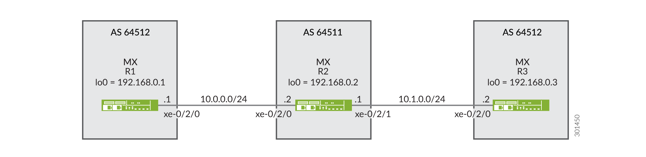 のBGPトポロジー
設定
CLIクイックコンフィグレーション
この例をすばやく設定するには、以下のコマンドをコピーしてテキストファイルに貼り付け、改行を削除して、ネットワーク構成に合わせて必要な詳細を変更してから、コマンドを [edit] 階層レベルのCLIにコピー&ペーストします。
デバイスR1
set interfaces xe-0/2/0 description R1-to-R2
set interfaces xe-0/2/0 unit 0 family inet address 10.0.0.1/30
set interfaces lo0 unit 0 family inet address 192.168.0.1/32
set protocols bgp family inet unicast loops 2
set protocols bgp group ext type external
set protocols bgp group ext export send-direct
set protocols bgp group ext peer-as 64511
set protocols bgp group ext neighbor 10.0.0.2
set policy-options policy-statement send-direct term 1 from protocol direct
set policy-options policy-statement send-direct term 1 then accept
set routing-options autonomous-system 64512
デバイスR2
set interfaces xe-0/2/0 description R2-to-R1
set interfaces xe-0/2/0 unit 0 family inet address 10.0.0.2/30
set interfaces xe-0/2/1 description R2-to-R3
set interfaces xe-0/2/1 unit 0 family inet address 10.1.0.1/30
set interfaces lo0 unit 0 family inet address 192.168.0.2/32
set protocols bgp group ext type external
set protocols bgp group ext advertise-peer-as
set protocols bgp group ext export send-direct
set protocols bgp group ext neighbor 10.0.0.1 peer-as 64512
set protocols bgp group ext neighbor 10.1.0.2 peer-as 64512
set policy-options policy-statement send-direct term 1 from protocol direct
set policy-options policy-statement send-direct term 1 then accept
set routing-options autonomous-system 64511
デバイスR3
set interfaces xe-0/2/0 description R3-to-R2
set interfaces xe-0/2/0 unit 0 family inet address 10.1.0.2/30
set interfaces lo0 unit 0 family inet address 192.168.0.3/32
set protocols bgp family inet unicast loops 2
set protocols bgp group ext type external
set protocols bgp group ext export send-direct
set protocols bgp group ext peer-as 64511
set protocols bgp group ext neighbor 10.1.0.1
set policy-options policy-statement send-direct term 1 from protocol direct
set policy-options policy-statement send-direct term 1 then accept
set routing-options autonomous-system 64512
手順
ステップバイステップの手順
次の例では、設定階層内のさまざまなレベルに移動する必要があります。CLIのナビゲーションについては、『Junos OS CLIユーザーガイド』の「設定モードでのCLIエディターの使用」を参照してください。
デバイスR1を設定するには:
-
デバイスインターフェイスを設定します。
[edit interfaces]
user@R1# set xe-0/2/0 description R1-to-R2
user@R1# set xe-0/2/0 unit 0 family inet address 10.0.0.1/30
user@R1# set lo0 unit 0 family inet address 192.168.0.1/32
-
BGPを設定します。
[edit protocols bgp group ext]
user@R1# set type external
user@R1# set peer-as 64511
user@R1# set neighbor 10.0.0.2
-
loops 2ステートメントを含めることで、デバイスR3からのルートがデバイスR1で非表示になるのを防ぎます。loops 2ステートメントは、ルートを非表示にすることなく、ローカルデバイス自身のAS番号を1回までASパスに表示できることを意味します。ローカルデバイスのAS番号がパス内で2回以上検知された場合、ルートは非表示になります。[edit protocols bgp family inet unicast] user@R1# set loops 2
-
直接ルートを送信するルーティングポリシーを設定します。
[edit policy-options policy-statement send-direct term 1]
user@R1# set from protocol direct
user@R1# set then accept
-
デバイスR2とのBGPピアリングセッションにエクスポートポリシーを適用します。
[edit protocols bgp group ext]
user@R1# set export send-direct
-
自律システム(AS)番号を設定します。
[edit routing-options ]
user@R1# set autonomous-system 64512
ステップバイステップの手順
デバイスR2を設定するには:
-
デバイスインターフェイスを設定します。
[edit interfaces]
user@R2# set xe-0/2/0 description R2-to-R1
user@R2# set xe-0/2/0 unit 0 family inet address 10.0.0.2/30
user@R2# set xe-0/2/1 description R2-to-R3
user@R2# set xe-0/2/1 unit 0 family inet address 10.1.0.1/30
user@R2# set lo0 unit 0 family inet address 192.168.0.2/32
-
BGPを設定します。
[edit  protocols bgp group ext]
user@R2# set type external
user@R2# set neighbor 10.0.0.1 peer-as 64512
user@R2# set neighbor 10.1.0.2 peer-as 64512
-
同じAS内で、あるEBGPピアから別のEBGPピアに学習されたルートをアドバタイズするように、デバイスR2を設定します。
言い換えると、デバイスR1とデバイスR3が同じAS内にあっても、デバイスR3から(およびその逆から)学習したデバイスR1のルートにアドバタイズします。
[edit  protocols bgp group ext]
user@R2# set advertise-peer-as
-
直接ルートを送信するルーティングポリシーを設定します。
[edit policy-options policy-statement send-direct term 1]
user@R2# set from protocol direct
user@R2# set then accept
-
エクスポートポリシーを適用します。
[edit protocols bgp group ext]
user@R2# set export send-direct
-
AS番号を設定します。
[edit routing-options]
user@R2# set autonomous-system 64511
結果
設定モードから、 show interfaces、 show protocols、 show policy-options、および show routing-options コマンドを入力して設定を確認します。出力に意図した設定が表示されない場合は、この例の手順を繰り返して設定を修正します。
デバイスR1
user@R1# show interfaces
xe-0/2/0 {
    description R1-to-R2;
    unit 0 {
        family inet {
            address 10.0.0.1/30;
        }
    }
}
lo0 {
    unit 0 {
        family inet {
            address 192.168.0.1/32;
        }
    }
}
user@R1# show protocols
bgp {
    family inet {
        unicast {
            loops 2;
        }
    }
    group ext {
        type external;
        export send-direct;
        peer-as 64511;
        neighbor 10.0.0.2;
    }
}
user@R1# show policy-options
policy-statement send-direct {
    term 1 {
        from protocol direct;
        then accept;
    }
}
user@R1# show routing-options
autonomous-system 64512;
デバイスR2
user@R2# show interfaces
xe-0/2/0 {
    description R2-to-R1;
    unit 0 {
        family inet {
            address 10.0.0.2/30;
        }
    }
}
xe-0/2/1 {
    description R2-to-R3;
    unit 0 {
        family inet {
            address 10.1.0.1/30;
        }
    }
}
lo0 {
    unit 0 {
        family inet {
            address 192.168.0.2/32;
        }
    }
}
user@R2# show protocols
bgp {
    group ext {
        type external;
        advertise-peer-as;
        export send-direct;
        neighbor 10.0.0.1 {
            peer-as 64512;
        }
        neighbor 10.1.0.2 {
            peer-as 64512;
        }
    }
}
user@R2# show policy-options
policy-statement send-direct {
    term 1 {
        from protocol direct;
        then accept;
    }
}
user@R2# show routing-options
autonomous-system 64511;
デバイスの設定が完了したら、設定モードから commit を入力します。
検証
設定が正常に機能していることを確認します。
BGPルートの検証
目的
デバイスR1とデバイスR3のルーティングテーブルに、予想されるルートが含まれていることを確認します。
アクション
-
デバイスR2で、BGP設定の
advertise-peer-asステートメントを無効にします。[edit protocols bgp group ext] user@R2# deactivate advertise-peer-as user@R2# commit
-
デバイスR3で、BGP設定の
loopsステートメントを無効にします。[edit protocols bgp family inet unicast ] user@R3# deactivate unicast loops user@R3# commit
-
デバイスR1で、デバイスR2にアドバタイズされているルートを確認します。
user@R1> show route advertising-protocol bgp 10.0.0.2
inet.0: 5 destinations, 6 routes (5 active, 0 holddown, 0 hidden)
  Prefix                  Nexthop              MED     Lclpref    AS path
* 10.0.0.0/30             Self                                    I
* 192.168.0.1/32          Self                                    I
-
デバイスR2で、デバイスR1からどのルートが受信されているかを確認します。
user@R2> show route receive-protocol bgp 10.0.0.1
inet.0: 7 destinations, 9 routes (7 active, 0 holddown, 0 hidden)
  Prefix                  Nexthop              MED     Lclpref    AS path
  10.0.0.0/30             10.0.0.1                                64512 I
* 192.168.0.1/32          10.0.0.1                                64512 I
-
デバイスR2で、デバイスR3にアドバタイズされているルートを確認します。
user@R2> show route advertising-protocol bgp 10.1.0.2
inet.0: 7 destinations, 9 routes (7 active, 0 holddown, 0 hidden)
  Prefix                  Nexthop              MED     Lclpref    AS path
* 10.0.0.0/30             Self                                    I
* 10.1.0.0/30             Self                                    I
* 192.168.0.2/32          Self                                    I
-
デバイスR2で、BGP設定の
advertise-peer-asステートメントをアクティブにします。[edit protocols bgp group ext] user@R2# activate advertise-peer-as user@R2# commit
-
デバイスR2で、デバイスR3にアドバタイズされているルートを再確認します。
user@R2> show route advertising-protocol bgp 10.1.0.2
inet.0: 7 destinations, 9 routes (7 active, 0 holddown, 0 hidden)
  Prefix                  Nexthop              MED     Lclpref    AS path
* 10.0.0.0/30             Self                                    I
* 10.1.0.0/30             Self                                    I
* 192.168.0.1/32          Self             64512 I
* 192.168.0.2/32          Self                                    I
* 192.168.0.3/32          10.1.0.2         64512 I
-
デバイスR3で、デバイスR2から受信したルートを確認します。
user@R3> show route receive-protocol bgp 10.1.0.1
inet.0: 5 destinations, 6 routes (5 active, 0 holddown, 0 hidden)
  Prefix                  Nexthop              MED     Lclpref    AS path
* 10.0.0.0/30             10.1.0.1                                64511 I
  10.1.0.0/30             10.1.0.1                                64511 I
* 192.168.0.2/32          10.1.0.1                                64511 I
-
デバイスR3で、BGP設定の
loopsステートメントを有効にします。[edit protocols bgp family inet unicast ] user@R3# activate unicast loops user@R3# commit
-
デバイスR3で、デバイスR2から受信したルートを再確認します。
user@R3> show route receive-protocol bgp 10.1.0.1 inet.0: 6 destinations, 8 routes (6 active, 0 holddown, 1 hidden) Prefix Nexthop MED Lclpref AS path * 10.0.0.0/30 10.1.0.1 64511 I 10.1.0.0/30 10.1.0.1 64511 I * 192.168.0.1/32 10.1.0.1 64511 64512 I * 192.168.0.2/32 10.1.0.1 64511 I
意味
まず、 advertise-peer-as ステートメントと loops ステートメントを無効にして、デフォルトの動作を調べることができます。デバイスR1は、デバイスR2にデバイスR1のループバックインターフェイスアドレス192.168.0.1/32へのルートを送信します。デバイスR2は、デバイスR3に対してこのルートをアドバタイズしません。 advertise-peer-as ステートメントを有効にした後、デバイスR2はデバイスR3に192.168.0.1/32ルートをアドバタイズします。デバイスR3は、 loops ステートメントがアクティブになるまで、このルートを受け入れません。
BGPループ検知の独立ASドメインで属性セットメッセージを無効化する
特定のルートの BGP ループ検知では、ルーティングインスタンスにローカル自律システム(AS)ドメインを使用します。デフォルトでは、すべてのルーティングインスタンスは、グローバル階層 routing-optionsで設定された単一のプライマリルーティングインスタンスドメインに属しています。そのため、BGPループ検知では、すべてのルーティングインスタンスに設定されたローカルASを使用します。ネットワーク設定によっては、このデフォルトの動作によってルートがループしたり非表示になったりすることがあります。簡潔にするために、「ローカルAS」を特定のルーティングインスタンスのASとして、グローバル設定またはプライマリルーティングインスタンスの「グローバルAS」と呼びます。
プライマリルーティングインスタンスのローカルASを制限するには、ルーティングインスタンスの独立したASドメインを設定します。独立ドメインはプライマリ ルーティング インスタンスから独立しており、独立ドメインの AS パスが他のドメインの AS パスおよび AS パス属性と共有されないようにします。
デフォルトでは、独立ドメインは推移的なパス属性128(属性セット)メッセージを使用して、内部のBGP(IBGP)コアを介して独立ドメインのBGP属性をトンネルします。ただし、多くの場合、独立ドメインの属性セットメッセージの動作は望ましくありません。ルーティングインスタンス内のローカルASの独立性を維持するためだけ独立ドメインを設定し、ルーティングインスタンスで指定されたローカルASに対してのみBGPループ検出を実行する場合は、属性セットメッセージを無効にすることができます。
独立ドメインで属性セットメッセージを無効にするには、 independent-domain no-attrset ステートメントを含めます。
独立ドメインのルーティングインスタンスを指定すると、ローカルASはそのルーティングインスタンスにのみ関連付けられます。つまり、BGPループ検知は、ルーティングインスタンスで定義されたローカルASのみを使用します。
関連項目
例:最適経路の選択時にASパス属性を無視する
同じ宛先への複数のBGPルートが存在する場合、BGPはパスのルート属性に基づいて最適なパスを選択します。最適経路の決定に影響を与えるルート属性の1つは、各ルートのASパスの長さです。短いASパスを持つルートが、長いASパスを持つルートよりも好まれます。通常は現実的ではありませんが、ルート選択プロセスでASパス長を無視することが求められる場合があります。この例では、ASパス属性を無視するようにルーティングデバイスを設定する方法を示しています。
要件
この例を設定する前に、デバイスの初期化以外の特別な設定は必要ありません。
概要
外部に接続されたルーティングデバイスでは、ASパス比較をスキップする目的は、外部BGP(EBGP)と内部BGP(IBGP)の決定を強制的に決定し、できるだけ早くネットワークからトラフィックを削除することです。内部接続されたルーティング・デバイスでは、IBGP 専用ルーターをローカルの外部接続ゲートウェイにデフォルト設定することができます。ローカルIBGPのみ(内部)ルーターは、ASパス比較をスキップし、決定木を下に移動して、最も近い内部ゲートウェイプロトコル(IGP)ゲートウェイ(最小のIGPメトリック)を使用します。これを行うと、これらのルーターに WAN 接続ではなく LAN 接続を強制的に使用させる効果的な方法となる可能性があります。
ネットワーク内のルーティングデバイスに as-path-ignore ステートメントを使用する場合、ルーティングループやコンバージェンスの問題を防ぐために、ネットワーク内の他のすべてのBGP対応デバイスにステートメントを含める必要がある場合があります。これは、IBGPパス比較に特に当てはまります。
この例では、デバイスR2は、デバイスR1およびデバイスR3からデバイスR4(10.4.4.4/32)のループバックインターフェイスアドレスについて学習しています。デバイスR1は、65001 65005 65004のASパスで10.4.4.4/32をアドバタイズしており、デバイスR3は65003 65004のASパスで10.4.4.4/32をアドバタイズしています。デバイスR2は、デバイスR3からの10.4.4.4/32へのパスがデバイスR1からのASパスよりも短いため、最適なパスとしてASを選択します。
この例では、デバイスR2のBGP設定を変更して、最適パスの選択でASパス長が使用されないようにします。
デバイスR1のルーターID(10.1.1.1)は、デバイスR3(10.3.3.3)よりも低いです。他のすべてのパス選択基準が等しい場合(または、このケースのように無視される場合)、デバイスR1から学習したルートが使用されます。ASパスパス属性が無視されているため、ルーターID値が低いため、デバイスR1へのパスが最適です。
図7は、サンプルのトポロジーを示しています。
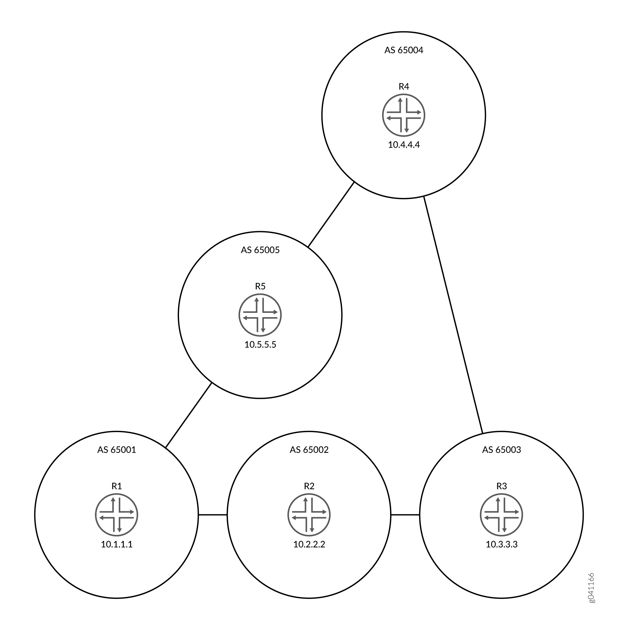 を無視するためのトポロジー
設定
CLIクイックコンフィグレーション
この例をすばやく設定するには、以下のコマンドをコピーしてテキスト ファイルに貼り付け、改行を削除して、ネットワーク構成に合わせて必要な詳細を変更し、 [edit] 階層レベルのCLIにコマンドをコピー アンド ペーストします。
デバイスR1
set interfaces fe-1/2/0 unit 1 family inet address 192.168.10.1/24 set interfaces fe-1/2/1 unit 10 family inet address 192.168.50.2/24 set interfaces lo0 unit 1 family inet address 10.1.1.1/32 set protocols bgp group ext type external set protocols bgp group ext export send-direct set protocols bgp group ext export send-static set protocols bgp group ext export send-local set protocols bgp group ext neighbor 192.168.10.2 peer-as 65002set protocols bgp group ext neighbor 192.168.50.1 peer-as 65005 set policy-options policy-statement send-direct term 1 from protocol direct set policy-options policy-statement send-direct term 1 then accept set policy-options policy-statement send-local term 1 from protocol local set policy-options policy-statement send-local term 1 then accept set policy-options policy-statement send-static term 1 from protocol static set policy-options policy-statement send-static term 1 then accept set routing-options static route 192.168.20.0/24 next-hop 192.168.10.2 set routing-options static route 192.168.30.0/24 next-hop 192.168.10.2 set routing-options static route 192.168.40.0/24 next-hop 192.168.50.1 set routing-options router-id 10.1.1.1 set routing-options autonomous-system 65001
デバイスR2
set interfaces fe-1/2/0 unit 2 family inet address 192.168.10.2/24 set interfaces fe-1/2/1 unit 3 family inet address 192.168.20.2/24 set interfaces lo0 unit 2 family inet address 10.2.2.2/32 set protocols bgp path-selection as-path-ignore set protocols bgp group ext type external set protocols bgp group ext export send-direct set protocols bgp group ext export send-static set protocols bgp group ext export send-local set protocols bgp group ext neighbor 192.168.10.1 peer-as 65001 set protocols bgp group ext neighbor 192.168.20.1 peer-as 65003 set policy-options policy-statement send-direct term 1 from protocol direct set policy-options policy-statement send-direct term 1 then accept set policy-options policy-statement send-local term 1 from protocol local set policy-options policy-statement send-local term 1 then accept set policy-options policy-statement send-static term 1 from protocol static set policy-options policy-statement send-static term 1 then accept set routing-options static route 192.168.50.0/24 next-hop 192.168.10.1 set routing-options static route 192.168.40.0/24 next-hop 192.168.10.1 set routing-options static route 192.168.30.0/24 next-hop 192.168.20.1 set routing-options router-id 10.2.2.2 set routing-options autonomous-system 65002
デバイスR3
set interfaces fe-1/2/0 unit 4 family inet address 192.168.20.1/24 set interfaces fe-1/2/1 unit 5 family inet address 192.168.30.1/24 set interfaces lo0 unit 3 family inet address 10.3.3.3/32 set protocols bgp group ext type external set protocols bgp group ext export send-direct set protocols bgp group ext export send-static set protocols bgp group ext export send-local set protocols bgp group ext neighbor 192.168.20.2 peer-as 65002 set protocols bgp group ext neighbor 192.168.30.2 peer-as 65004 set policy-options policy-statement send-direct term 1 from protocol direct set policy-options policy-statement send-direct term 1 then accept set policy-options policy-statement send-local term 1 from protocol local set policy-options policy-statement send-local term 1 then accept set policy-options policy-statement send-static term 1 from protocol static set policy-options policy-statement send-static term 1 then accept set routing-options static route 192.168.10.0/24 next-hop 192.168.20.2 set routing-options static route 192.168.50.0/24 next-hop 192.168.20.2 set routing-options static route 192.168.40.0/24 next-hop 192.168.30.2 set routing-options router-id 10.3.3.3 set routing-options autonomous-system 65003
デバイスR4
set interfaces fe-1/2/0 unit 6 family inet address 192.168.30.2/24
set interfaces fe-1/2/1 unit 7 family inet address 192.168.40.1/24
set interfaces lo0 unit 4 family inet address 10.4.4.4/32
set protocols bgp group ext type external
set protocols bgp group ext export send-direct
set protocols bgp group ext export send-static
set protocols bgp group ext export send-local
set protocols bgp group ext neighbor 192.168.30.1 peer-as 65003
set protocols bgp group ext neighbor 192.168.40.2 peer-as 65005
set policy-options policy-statement send-direct term 1 from protocol direct
set policy-options policy-statement send-direct term 1 then accept
set policy-options policy-statement send-local term 1 from protocol local
set policy-options policy-statement send-local term 1 then accept
set policy-options policy-statement send-static term 1 from protocol static
set policy-options policy-statement send-static term 1 then accept
set routing-options static route 192.168.10.0/24 next-hop 192.168.40.2
set routing-options static route 192.168.50.0/24 next-hop 192.168.40.2
set routing-options static route 192.168.40.0/24 next-hop 192.168.30.1
set routing-options router-id 10.4.4.4
set routing-options autonomous-system 65004
デバイスR5
set interfaces fe-1/2/0 unit 8 family inet address 192.168.40.2/24 set interfaces fe-1/2/1 unit 9 family inet address 192.168.50.1/24 set interfaces lo0 unit 5 family inet address 10.5.5.5/32 set protocols bgp group ext type external set protocols bgp group ext export send-direct set protocols bgp group ext export send-static set protocols bgp group ext export send-local set protocols bgp group ext neighbor 192.168.40.1 peer-as 65004 set protocols bgp group ext neighbor 192.168.50.2 peer-as 65001 set policy-options policy-statement send-direct term 1 from protocol direct set policy-options policy-statement send-direct term 1 then accept set policy-options policy-statement send-local term 1 from protocol local set policy-options policy-statement send-local term 1 then accept set policy-options policy-statement send-static term 1 from protocol static set policy-options policy-statement send-static term 1 then accept set routing-options static route 192.168.10.0/24 next-hop 192.168.50.2 set routing-options static route 192.168.20.0/24 next-hop 192.168.50.2 set routing-options static route 192.168.30.0/24 next-hop 192.168.40.1 set routing-options router-id 10.5.5.5 set routing-options autonomous-system 65005
デバイスR2の設定
ステップバイステップの手順
次の例では、設定階層のさまざまなレベルに移動する必要があります。CLIのナビゲーションについては、『Junos OS CLIユーザーガイド』の「構成モードでのCLIエディターの使用」を参照してください。
デバイスR2を設定するには:
-
インターフェイスを設定します。
[edit interfaces] user@R2# set fe-1/2/0 unit 2 family inet address 192.168.10.2/24 user@R2# set fe-1/2/1 unit 3 family inet address 192.168.20.2/24 user@R2# set lo0 unit 2 family inet address 10.2.2.2/32
-
EBGPを設定します。
[edit protocols bgp group ext] user@R2# set type external user@R2# set export send-direct user@R2# set export send-static user@R2# set export send-local user@R2# set neighbor 192.168.10.1 peer-as 65001 user@R2# set neighbor 192.168.20.1 peer-as 65003
-
Junos OSパス選択アルゴリズムで自律システム(AS)パス属性が無視されるように設定します。
[edit protocols bgp] user@R2# set path-selection as-path-ignore
-
ルーティングポリシーを設定します。
[edit policy-options] user@R2# set policy-statement send-direct term 1 from protocol direct user@R2# set policy-statement send-direct term 1 then accept user@R2# set policy-statement send-local term 1 from protocol local user@R2# set policy-statement send-local term 1 then accept user@R2# set policy-statement send-static term 1 from protocol static user@R2# set policy-statement send-static term 1 then accept
-
いくつかのスタティックルートを設定します。
[edit routing-options static] user@R2# set route 192.168.50.0/24 next-hop 192.168.10.1 user@R2# set route 192.168.40.0/24 next-hop 192.168.10.1 user@R2# set route 192.168.30.0/24 next-hop 192.168.20.1
-
自律システム(AS)番号とルーターIDを設定します。
[edit routing-options] user@R2# set router-id 10.2.2.2 user@R2# set autonomous-system 65002
結果
設定モードから、 show interfaces、 show policy-options、 show protocols、および show routing-options コマンドを入力して設定を確認します。出力に意図した設定が表示されない場合は、この例の手順を繰り返して設定を修正します。
user@R2# show interfaces
fe-1/2/0 {
unit 2 {
family inet {
address 192.168.10.2/24;
}
}
}
fe-1/2/1 {
unit 3 {
family inet {
address 192.168.20.2/24;
}
}
}
lo0 {
unit 2 {
family inet {
address 10.2.2.2/32;
}
}
}
user@R2# show policy-options
policy-statement send-direct {
term 1 {
from protocol direct;
then accept;
}
}
policy-statement send-local {
term 1 {
from protocol local;
then accept;
}
}
policy-statement send-static {
term 1 {
from protocol static;
then accept;
}
}
user@R2# show protocols
bgp {
path-selection as-path-ignore;
group ext {
type external;
export [ send-direct send-static send-local ];
neighbor 192.168.10.1 {
peer-as 65001;
}
neighbor 192.168.20.1 {
peer-as 65003;
}
}
}
user@R2# show routing-options
static {
route 192.168.50.0/24 next-hop 192.168.10.1;
route 192.168.40.0/24 next-hop 192.168.10.1;
route 192.168.30.0/24 next-hop 192.168.20.1;
}
router-id 10.2.2.2;
autonomous-system 65002;
デバイスの設定が完了したら、設定モードから コミット を入力します。ネットワーク内の他のデバイスでも設定を繰り返し、必要に応じてインターフェイス名とIPアドレスを変更します。
検証
設定が正常に機能していることを確認します。
ネイバーステータスの確認
目的
デバイスR2から、AS 4に到達するためのアクティブパスが、AS 65003を介さず、AS 65001およびAS 65005を経由していることを確認します。
as-path-ignoreステートメントの機能を検証するには、restart routingコマンドを実行してアクティブパスを強制的に再評価する必要がある場合があります。これは、BGPの場合、両方のパスが外部にある場合、Junos OSの動作は現在アクティブなパスを優先するためです。この動作は、ルートフラップを最小限に抑えるのに役立ちます。実稼働ネットワークでルーティングプロトコルプロセスを再起動する際は注意が必要です。
アクション
動作モードから、 restart routing コマンドを入力します。
user@R2> restart routing Routing protocols process started, pid 49396
動作モードから、 show route 10.4.4.4 protocol bgp コマンドを入力します。
user@R2> show route 10.4.4.4 protocol bgp
inet.0: 12 destinations, 25 routes (12 active, 0 holddown, 4 hidden)
+ = Active Route, - = Last Active, * = Both
10.4.4.4/32 *[BGP/170] 00:00:12, localpref 100
AS path: 65001 65005 65004 I
> to 192.168.10.1 via fe-1/2/0.2
[BGP/170] 00:00:08, localpref 100
AS path: 65003 65004 I
> to 192.168.20.1 via fe-1/2/1.3
意味
アスタリスク(*)は、R1から学習したパスの横にあり、これがアクティブなパスであることを意味します。アクティブパスのASパスは65001 65005 65004で、これはルーターR3から学習した非アクティブパスのASパス(65003 65004)よりも長いです。
ASパスからのプライベートAS番号の削除について
デフォルトでは、BGPがリモートシステムへのASパスをアドバタイズする場合、プライベートAS番号を含むすべてのAS番号が含まれます。ASパスからプライベートAS番号を削除するようにソフトウェアを設定できます。これを行うと、以下のいずれかの状況に該当する場合に有効です。
接続を提供するリモートASはマルチホームですが、ローカルASに対してのみ接続されます。
リモートASには、正式に割り当てられたAS番号がありません。
リモートASをローカルASのコンフェデレーションメンバーASにすることは適切ではありません。
ほとんどの企業は、独自のAS番号を取得しています。企業によっては、自社のパブリックASネットワークに接続するためにプライベートAS番号を使用することもあります。このような企業は、事業を行う地域ごとに異なるプライベートAS番号を使用している場合があります。どのような実装でも、プライベートAS番号をインターネットに知らせることは避けなければなりません。サービスプロバイダは、 remove-private ステートメントを使用して、インターネットへのプライベートAS番号のアドバタイズを防止できます。
企業のシナリオにおいて、社内に複数のAS番号があり、そのうちのいくつかはプライベートAS番号で、1つはパブリックAS番号が付いているとします。パブリックAS番号を持つものは、サービスプロバイダに直接接続しています。サービスプロバイダに直接接続するASでは、 remove-private ステートメントを使用して、サービスプロバイダに送信されるアドバタイズメント内のプライベートAS番号を除外できます。
AS番号は、ASパスの左端(ASパスが最後に追加された端)から始まるASパスから削除されます。ルーティングデバイスは、最初の非プライベートASまたはピアのプライベートASが見つかったときに、プライベートASの検索を停止します。ASパスに外部BGP(EBGP)ネイバーのAS番号が含まれている場合、BGPはプライベートAS番号を削除しません。
Junos OS 10.0R2以降では、ASパスのAS番号と一致するAS番号を持つEBGPピアにプレフィックスを送信する必要がある場合は、remove-privateステートメントではなくas-overrideステートメントの使用を検討してください。
この操作は、該当する場合、コンフェデレーションメンバーのASがASパスからASパスから削除された後に実行されます。
ソフトウェアは、IANA(IANA)割り当てられた番号ドキュメントで定義されている範囲、つまりプライベートと見なされる一連のAS番号のセットを認識した上で事前設定されています。プライベートとして予約された 16 ビット AS 番号のセットは、64,512 から 65,534 までの範囲です 。プライベートとして予約された32ビットAS番号は、4,200,000,000から4,294,967,294までの範囲です。
関連項目
例:ASパスからプライベートAS番号を削除する AS 番号
ここでは、アドバタイズされたASパスからプライベートAS番号を削除して、プライベートAS番号がインターネットに通知されないようにする例を示しています。
要件
この例を設定する前に、デバイスの初期化以外の特別な設定は必要ありません。
概要
サービスプロバイダとエンタープライズネットワークは、 remove-private ステートメントを使用して、インターネットへのプライベートAS番号のアドバタイズを防止します。 remove-private ステートメントは、アウトバウンド方向で機能します。パブリックAS番号を持ち、プライベートAS番号を持つ1つ以上のデバイスに接続されたデバイスで remove-private ステートメントを設定します。一般的に、プライベートAS番号を持つデバイスにはこのステートメントを設定しません。
図8は、サンプルのトポロジーを示しています。
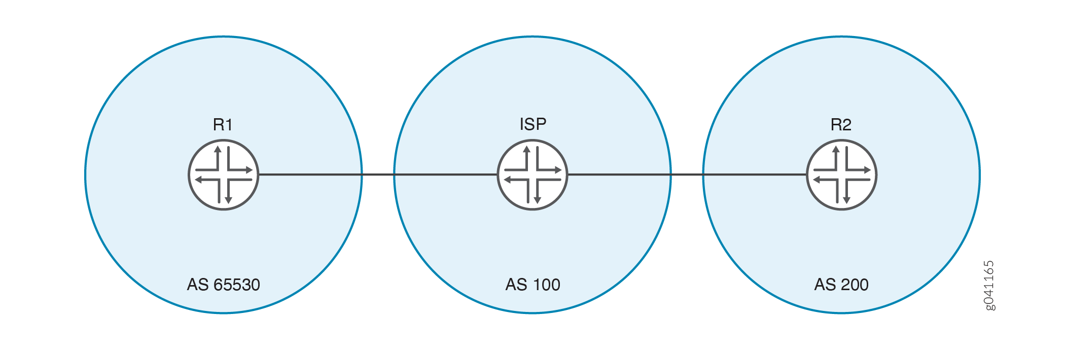 からプライベートASを削除するためのトポロジー
この例では、デバイスR1はプライベートAS番号65530を使用してサービスプロバイダに接続しています。この例では、デバイスR1のプライベートAS番号がデバイスR2に通知されないようにするために、デバイスISPに設定された remove-private ステートメントを示しています。デバイスR2は、サービスプロバイダのAS番号のみを確認します。
BGPオプション remove-private を追加または削除すると、影響を受けるBGPピアリングセッションがフラップされます。
設定
CLIクイックコンフィグレーション
この例をすばやく設定するには、以下のコマンドをコピーしてテキスト ファイルに貼り付け、改行を削除して、ネットワーク構成に合わせて必要な詳細を変更し、 [edit] 階層レベルのCLIにコマンドをコピー アンド ペーストします。
デバイスR1
set interfaces fe-1/2/0 unit 1 family inet address 192.168.10.1/24
set interfaces lo0 unit 1 family inet address 10.10.10.1/32
set protocols bgp group ext type external
set protocols bgp group ext export send-direct
set protocols bgp group ext export send-static
set protocols bgp group ext peer-as 100
set protocols bgp group ext neighbor 192.168.10.10
set policy-options policy-statement send-direct term 1 from protocol direct
set policy-options policy-statement send-direct term 1 then accept
set policy-options policy-statement send-static term 1 from protocol static
set policy-options policy-statement send-static term 1 then accept
set routing-options static route 192.168.20.0/24 next-hop 192.168.10.10
set routing-options autonomous-system 65530
デバイスISP
set interfaces fe-1/2/0 unit 2 family inet address 192.168.10.10/24 set interfaces fe-1/2/1 unit 3 family inet address 192.168.20.20/24 set interfaces lo0 unit 2 family inet address 10.10.0.1/32 set protocols bgp group ext type external set protocols bgp group ext neighbor 192.168.10.1 peer-as 65530 set protocols bgp group ext neighbor 192.168.20.1 remove-private set protocols bgp group ext neighbor 192.168.20.1 peer-as 200 set routing-options autonomous-system 100
デバイスR2
set interfaces fe-1/2/0 unit 4 family inet address 192.168.20.1/24 set interfaces lo0 unit 3 family inet address 10.10.20.1/32 set protocols bgp group ext type external set protocols bgp group ext export send-direct set protocols bgp group ext export send-static set protocols bgp group ext peer-as 100 set protocols bgp group ext neighbor 192.168.20.20 set policy-options policy-statement send-direct term 1 from protocol direct set policy-options policy-statement send-direct term 1 then accept set policy-options policy-statement send-static term 1 from protocol static set policy-options policy-statement send-static term 1 then accept set routing-options static route 192.168.10.0/24 next-hop 192.168.20.20 set routing-options autonomous-system 200
デバイスISP
ステップバイステップの手順
次の例では、設定階層のさまざまなレベルに移動する必要があります。CLIのナビゲーションについては、『Junos OS CLIユーザーガイド』の「構成モードでのCLIエディターの使用」を参照してください。
デバイスISPを設定するには:
-
インターフェイスを設定します。
[edit interfaces] user@ISP# set fe-1/2/0 unit 2 family inet address 192.168.10.10/24 user@ISP# set fe-1/2/1 unit 3 family inet address 192.168.20.20/24 user@ISP# set lo0 unit 2 family inet address 10.10.0.1/32
-
EBGPを設定します。
[edit protocols bgp group ext] user@ISP# set type external user@ISP# set neighbor 192.168.10.1 peer-as 65530 user@ISP# set neighbor 192.168.20.1 peer-as 200
-
自律システム(AS)200(デバイスR2)のネイバーに対して、アドバタイズされたASパスからプライベートAS番号を削除します。
[edit protocols bgp group ext] user@ISP# set neighbor 192.168.20.1 remove-private
-
AS番号を設定します。
[edit routing-options] user@ISP# set autonomous-system 100
結果
設定モードから、 show interfaces、 show protocols、 show routing-options コマンドを入力して設定を確認します。出力に意図した設定が表示されない場合は、この例の手順を繰り返して設定を修正します。
user@ISP# show interfaces
fe-1/2/0 {
unit 2 {
family inet {
address 192.168.10.10/24;
}
}
}
fe-1/2/1 {
unit 3 {
family inet {
address 192.168.20.20/24;
}
}
}
lo0 {
unit 2 {
family inet {
address 10.10.0.1/32;
}
}
}
user@ISP# show protocols
bgp {
group ext {
type external;
neighbor 192.168.10.1 {
peer-as 65530;
}
neighbor 192.168.20.1 {
remove-private;
peer-as 200;
}
}
}
user@ISP# show routing-options autonomous-system 100;
デバイスの設定が完了したら、設定モードから コミット を入力します。デバイスR1とデバイスR2で設定を繰り返し、必要に応じてインターフェイス名とIPアドレスを変更し、ルーティングポリシー設定を追加します。
検証
設定が正常に機能していることを確認します。
ネイバーステータスの確認
目的
デバイスISPがデバイスR2とのネイバーセッションで remove-private 設定を有効にしていることを確認します。
アクション
動作モードから、 show bgp neighbor 192.168.20.1 コマンドを入力します。
user@ISP> show bgp neighbor 192.168.20.1
Peer: 192.168.20.1+179 AS 200 Local: 192.168.20.20+60216 AS 100
Type: External State: Established Flags: <ImportEval Sync>
Last State: OpenConfirm Last Event: RecvKeepAlive
Last Error: None
Options: <Preference RemovePrivateAS PeerAS Refresh>
Holdtime: 90 Preference: 170
Number of flaps: 0
Peer ID: 10.10.20.1 Local ID: 10.10.0.1 Active Holdtime: 90
Keepalive Interval: 30 Peer index: 0
BFD: disabled, down
Local Interface: fe-1/2/1.3
NLRI for restart configured on peer: inet-unicast
NLRI advertised by peer: inet-unicast
NLRI for this session: inet-unicast
Peer supports Refresh capability (2)
Stale routes from peer are kept for: 300
Peer does not support Restarter functionality
NLRI that restart is negotiated for: inet-unicast
NLRI of received end-of-rib markers: inet-unicast
NLRI of all end-of-rib markers sent: inet-unicast
Peer supports 4 byte AS extension (peer-as 200)
Peer does not support Addpath
Table inet.0 Bit: 10001
RIB State: BGP restart is complete
Send state: in sync
Active prefixes: 1
Received prefixes: 3
Accepted prefixes: 2
Suppressed due to damping: 0
Advertised prefixes: 1
Last traffic (seconds): Received 10 Sent 16 Checked 55
Input messages: Total 54 Updates 3 Refreshes 0 Octets 1091
Output messages: Total 54 Updates 1 Refreshes 0 Octets 1118
Output Queue[0]: 0
意味
RemovePrivateASオプションは、デバイスISPに予想される設定があることを示しています。
ルーティングテーブルのチェック
目的
デバイスに予想されたルートとASパスがあることを確認します。
アクション
動作モードから、 show route protocol bgp コマンドを入力します。
user@R1> show route protocol bgp
inet.0: 5 destinations, 5 routes (5 active, 0 holddown, 0 hidden)
+ = Active Route, - = Last Active, * = Both
10.10.20.1/32 *[BGP/170] 00:28:57, localpref 100
AS path: 100 200 I
> to 192.168.10.10 via fe-1/2/0.1
user@ISP> show route protocol bgp
inet.0: 7 destinations, 11 routes (7 active, 0 holddown, 2 hidden)
+ = Active Route, - = Last Active, * = Both
10.10.10.1/32 *[BGP/170] 00:29:40, localpref 100
AS path: 65530 I
> to 192.168.10.1 via fe-1/2/0.2
10.10.20.1/32 *[BGP/170] 00:29:36, localpref 100
AS path: 200 I
> to 192.168.20.1 via fe-1/2/1.3
192.168.10.0/24 [BGP/170] 00:29:40, localpref 100
AS path: 65530 I
> to 192.168.10.1 via fe-1/2/0.2
192.168.20.0/24 [BGP/170] 00:29:36, localpref 100
AS path: 200 I
> to 192.168.20.1 via fe-1/2/1.3
user@R2> show route protocol bgp
inet.0: 5 destinations, 5 routes (5 active, 0 holddown, 0 hidden)
+ = Active Route, - = Last Active, * = Both
10.10.10.1/32 *[BGP/170] 00:29:53, localpref 100
AS path: 100 I
> to 192.168.20.20 via fe-1/2/0.4
意味
デバイスISPは、デバイスR1へのASパスにプライベートAS番号65530を持っています。ただし、デバイスISPは、このプライベートAS番号をデバイスR2にアドバタイズしません。これは、デバイスR2のルーティングテーブルに示されています。デバイスR2からデバイスR1へのパスには、デバイスISPのAS番号のみが含まれます。
remove-privateステートメントの非アクティブ化時にASパスを確認する
目的
remove-privateステートメントなしで、プライベートAS番号がデバイスR2のルーティングテーブルに表示されることを確認します。
アクション
デバイスISPの設定モードから、 deactivate remove-private コマンドを入力し、デバイスR2のルーティングテーブルを再確認します。
[protocols bgp group ext neighbor 192.168.20.1] user@ISP# deactivate remove-private user@ISP# commit
user@R2> show route protocol bgp
inet.0: 5 destinations, 5 routes (5 active, 0 holddown, 0 hidden)
+ = Active Route, - = Last Active, * = Both
10.10.10.1/32 *[BGP/170] 00:00:54, localpref 100
AS path: 100 65530 I
> to 192.168.20.20 via fe-1/2/0.4
意味
プライベートAS番号65530は、デバイスR2のデバイスR1へのASパスに表示されます。
変更履歴テーブル
サポートされる機能は、使用しているプラットフォームとリリースによって決まります。 機能エクスプローラー を使用して、機能がお使いのプラットフォームでサポートされているかどうかを確認します。