External Multicast with PIM IRB
Earlier chapters in this book explored how non-optimized and optimized inter-subnet multicast works in an EVPN data center fabric. This chapter looks into how external multicast (multicast from and to outside of EVPN data center fabric) works in an optimized way following PIM and EVPN procedures. Since optimization is a paradigm within the fabric, the procedures described for External Multicast are the same for fabric topologies whether multicast is optimized or not.
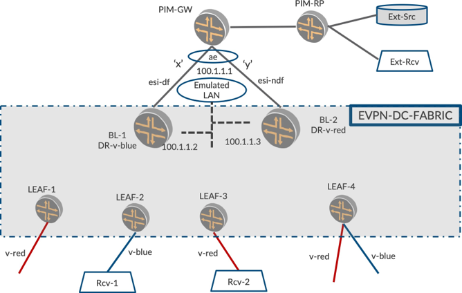
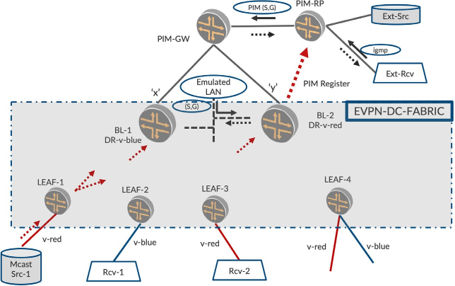
The EVPN data center fabric typically has two L3-PIM devices (BL-1 and BL-2) for inter-subnet multicast as described in EVPN Inter-VLAN Multicast Routing without Optimization chapter. The two BL devices are deployed for redundancy purposes. It is commonplace that such an EVPN data center fabric is to be connected to the outside world to send and receive multicast traffic to and from the data center.
By the end of this chapter you should have a fair understanding of the different methods in which the data center fabric can be connected to the outside world and the procedures that are involved.
The following two approaches are considered best practice for external multicast deployments.
Using classic L3-links (therefore, IP addresses configured on each link)
Using L2-link and family bridge (using a MVLAN with EVPN multihomed procedures)
In this chapter, we build on the building blocks of PIM and EVPN multihoming procedures to describe traffic flows in external multicast scenarios. There are two scenarios.
Source in the outside world: Listeners inside the fabric.
Source inside the fabric: Listeners outside the fabric.
Once we understand the procedures for the above, we can describe the flows for sources existing inside or/ and outside the fabric with listeners existing inside or/and outside the fabric.:
Source in the outside world: Listeners inside the fabric as well as in the outside world
Source inside the fabric: Listeners inside the fabric as well as in the outside world
Thus we can deploy multicast sources and listeners inside and outside of the fabric, and be able to explain the procedures involved in signaling and multicast traffic forwarding from sources and listeners.
External Multicast with Layer 3 Connectivity
To enable this effort, external multicast using PIM with classic L3 connectivity is described. And for this discussion, let’s call the device that connects the fabric to the outside world Gateway (PIM-GW shown in Figure 1).
There are two BL devices in the fabric that run PIM on IRB. The PIM-GW can be connected to both BL-1 and BL-2 over classic L3 links. The PIM-GW sees BL-1 as a PIM neighbor on one L3-interface, say interface x, on subnet 10.1.1.0/24. The PIM-GW sees BL-2 as another PIM neighbor on another L3-interface, say interface y, on subnet 50.1.1.0/24. Unicast reachability is configured between the BLs, PIM-GW, PIM-RP, etc.
It’s possible that the PIM-GW can be connected to only one Spine (either by network design or due to a link failure). In addition, the BLs can be connected to multiple GWs over multiple L3 links. And when link ‘y’ between PIM-GW and BL-2 goes down, BL-2 should have unicast reachability to PIM-GW and PIM-RP. This is typically ensured by having a dedicated L3-link between BL-1 and BL-2. The reachability can be ensured by configuring a unicast routing protocol on one of the IRBs on the BLs.
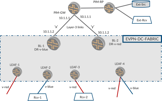
The PIM-GW is the device that connects the EVPN-DC-Fabric to the outside world. The PIM-GW may itself be the PIM-RP or may be connected over multiple routers to a PIM-RP. The PIM-RP may be connected to external multicast sources and listeners directly or over multiple hops of routers. Procedures and packet flows for the following will be discussed:
Listeners inside the fabric. Source outside the fabric
Source inside the fabric: Listeners outside the fabric
Layer 3 Connectivity: Listener Inside the Fabric. Source Outside the Fabric
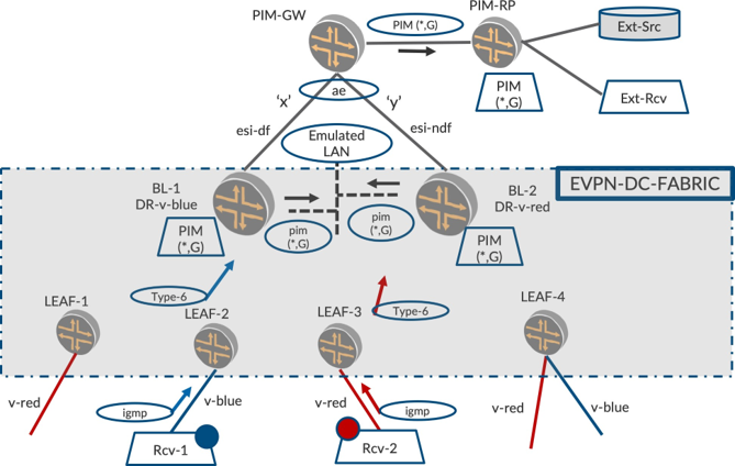
As shown by the red and blue VLANs in Figure 2 below, there is listener interest for group G, let’s say 235.1.1.1. For the purpose of this example, Rcv-1 sends an IGMP report on v-blue and Rcv-2 sends an IGMP report on v-red.
On receiving the IGMP reports, LEAF-2 and LEAF-3 send equivalent Type-6 routes on v-red and v-blue. On receiving the Type-6 routes, BL-1 and BL-2 create PIM (*,G) states on IRB.red and IRB.blue, respec- tively, due to PIM DRship.
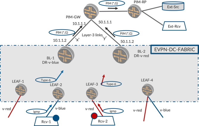
When the BLs look to propagate the Join towards RP, they perform unicast route lookup towards RP address and send a PIM (*,G) Join towards RP. BL-1 sends the PIM Join on interface ‘x’ and BL-2 sends the join on interface ‘y’ towards the PIM-GW based on the best unicast path to RP.
PIM-GW receives (*,G) Join on both of its interfaces ‘x’ and ‘y’ and creates PIM (*,G) state with OIL as a list having both ‘x’ and ‘y’. PIM-GW performs lookup towards RP and sends the Join to the device PIM-RP.
Overall, PIM states are created on BLs, PIM-GW, and PIM-RP with the appropriate PIM Join states having corresponding OILs.
Multicast Traffic Forwarding
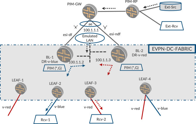
Once the PIM Join lands in PIM-RP it resides there and gets periodically refreshed from downstream. When a multicast source becomes alive, PIM-RP gets to know of the source by virtue of PIM Registration (not shown Figure 3, as this is plain vanilla PIM behavior). After this, PIM-RP sends a (S,G) Join towards the source.
When the multicast source outside the fabric (Ext-Src) starts sending traffic, (shown as dotted lines in Figure 3), the traffic reaches RP. Since RP has a PIM Join state created for the group, as described in an earlier section, RP sends the traffic towards PIM-GW. Now, PIM-GW, on receiving traffic from RP, routes onto its OIL, the two L3 interfaces, ‘x’ and ‘y’.
When the BLs receive the traffic on the L3 links, they route the traffic from the L3-link onto the IRBs and forward the traffic to the EVPN core. So BL-1 routes traffic coming on interface ‘x’ onto IRB.blue, and sends the traffic towards LEAF-2 and BL-2 on v-blue per procedures in EVPN Intra-VLAN Multicast with Optimization chapter. Similarly, BL-2 routes traffic coming on interface ‘y’ onto IRB.red, and sends the traffic towards LEAF-3 and BL-1 on v-red.
This routing on BL-1 from interface ‘x’ onto IRB.blue is similar to Inter-VLAN multicast routing. PIM routes at Layer 3 from ‘x’ onto IRB.blue. The routed multicast traffic on IRB.blue is sent to interested listener PEs using Selective Forwarding. If there are any local interfaces on BL-1 on v-blue, the routed traffic will be flooded to it too.
Layer 3 Connectivity: Listener Outside the Fabric. Source Inside the Fabric
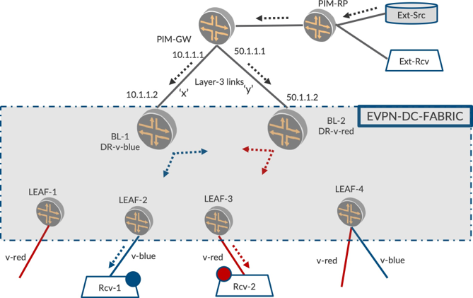
In Figure 4, we have Ext-Rcv, a listener outside the fabric and Mcast-Src-1, inside the fabric. When listener Ext-Rcv sends an IGMP report, a PIM (*,G) Join state is created on RP. (The PIM Join from a router connected to Ext-Rcv may arrive at RP hop-by-hop.)
When Mcast-Src-1 starts sending traffic on v-red, LEAF-1 floods the traffic towards the EVPN core with Selective Forwarding procedures. This traffic reaches IRB.red on BL-1 and BL-2.The PIM DR for IRB.red, BL-2, performs PIM registration for the (S,G) information.
The PIM-RP, on learning of the source, looks to join the multicast source natively and hence initiates PIM (S,G) Join towards source. This PIM (S,G) Join reaches PIM-GW.
PIM-GW now conducts unicast route lookup to the source to pull traffic. PIM-GW has two paths to reach source over ‘x’ and ‘y.’ PIM-GW picks one of the interfaces to send the PIM (S,G) Join, say ‘x,’ and sends the Join. PIM-GW does not send the Join on ‘y.’
When BL-1 receives the PIM (S,G) Join on ‘x’, it routes the traffic from IRB.red to ‘x’. Once traffic reaches PIM-GW on interface ‘x’, PIM-GW sends the traffic to RP and in turn, RP to Ext-Rcv, thus reaching a listener outside the fabric.
PIM-GW, may have a scheme to load balance the PIM Joins sent over the two interfaces. Some (S,G)s may be sent to BL-1 and others may be sent to BL-2. This load balancing can be performed based on Join counts on the interfaces or based on prefix-hashing of the (S,G) tuple.
External Multicast with L2 Connectivity - MVLAN
Earlier we explored the nuances of connecting the EVPN fabric to the external world over L3-connectivity. Now let’s explore the connectivity of EVPN fabric to the external world over L2-connectivity.
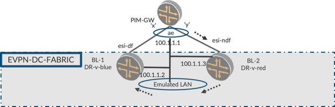
What does ‘L2-connectivity’ mean in this context? The physical links between GW and BLs ‘x’ and ‘y’ will remain the same as earlier. Instead of configuring separate subnets between PIM-GW and Spines, in this scheme we will configure the PIM-GW and BLs to be on the same bridge. Yes, we will mimic a LAN behavior between PIM-GW and BLs so that they see each other on the same subnet.
Though there are only two physical links (PIM-GW to BL-1 and PIM-GW to BL-2), the ‘bridge’ or ‘emulated LAN’ behavior will ensure that even when, say, the link between PIM-GW and SPINE-2 goes down, the devices can see each other on the subnet.
Sounds nice. How is this achieved? EVPN multihoming, of course. How? Begin by reviewing Figure 5.
On BLs, we configured an EVPN VLAN with appropriate VLAN-ID and VNID for this purpose. This is a typical EVPN VLAN— nothing special. Since this VLAN is going to build the emulated LAN towards PIM-GW for us, however, let’s call it a MVLAN (multicast-VLAN). Please keep in mind that MVLAN is just a normal VLAN in terms of configuration and procedures. For easier understanding, we’ll call it MVLAN since it is the VLAN used to connect the GW and BLs in a subnet (LAN).
Layer 2 Connectivity: MVLAN Configuration and Procedures
To configure a MVLAN with VLAN and VNIDs, add interface ‘x’ on BL-1 as part of the MVLAN by configuring family ‘bridge.’ Also, add interface ‘y’ on BL-2 as part of the MVLAN by configuring family ‘bridge.’
EVPN Multi-homing: Since the BLs are multihomed on the L2 interfaces ‘x’ and ‘y’, EVPN ESI is configured. Say, BL-1’s interface ‘x’ is elected EVPN-DF. As with classic EVPN multihoming, the other end of the multihomed PEs should be an AE bundle. So, configure the AE bundle on the PIM-GW.
IRB.MVLAN and Routing protocols: Having come thus far, let’s make it appear as three PIM routers on a LAN. Towards this end enable IRB on the MVLANs on the BLs. Configure L3-IP addresses on the IRBs and on the AE interface on the PIM-GW. Only the three IP addresses should be part of the same subnet. (for example, 100.1.1.1/24, 100.1.1.2/24, 100.1.1.3/24).
Properties of MVLAN: This MVLAN has all the properties of a regular LAN, therefore any BUM packet sent on the MVLAN will be received by all the devices on the MVLAN. Routing protocols can be enabled on this MVLAN. When configuring OSPF and PIM on these IRB interfaces on BLs and on AE interface on PIM-GW, you can see that they see each other as OSPF and PIM neighbors. Now that we have built an emulated LAN, let’s explore some first principles of how it came to be.
Layer 2 Connectivity: PIM-GW to BLs Multicast Forwarding
When the device PIM-GW sends a multicast packet, say, an OSPF hello packet (destination address is a multicast address 224.0.0.5) on an AE bundle interface, the packet will be sent on any one of the member links of the AE bundle.
If the packet is sent on interface ‘y,’ when it reaches BL-2, BL-2 sees it as a multicast L2-frame arriving on the MVLAN since family ‘bridge’ is configured on this interface.
BL-2 has two responsibilities:
L2-switch one copy of the frame towards EVPN core using Ingress Replication.
Remove L2-headers and punt the L3-packet to the IRB.MVLAN interface.
Due to ‘a’, this L2-frame reaches BL-1 over the EVPN core. Upon receiving this L2-frame, BL-1 has two responsibilities:
L2-switch one copy of the frame to access (accounting for DF and local bias).
Remove L2-headers and punt the L3-packet to the IRB.MVLAN interface.
You can see from all of this that the OSPF hello packet from PIM-GW is received on both of the BLs’ IRB interface. The above procedures apply for any multicast packets that come from PIM-GW towards BLs.
The same procedures apply for multicast packets that transit PIM-GW and reach BLs. Therefore, when PIM-RP forwards multicast traffic to PIM-GW and PIM-GW forwards it over the AE interface towards BLs, both BLs will receive the traffic on IRB.MVLAN.
Suppose interface ‘y’ goes down. PIM-GW, when forwarding traffic on the AE bundle towards the BLs will be seamless because the PIM-GW will now send on the other member link of the bundle, namely ‘x’. This traffic will reach BL-1 over the access interface and will reach BL-2 over the EVPN emulated LAN. Thus, both Spines will receive traffic when a link goes down.
Layer2 Connectivity: BL to the Other BL and PIMGW Multicast Forwarding
Let us quickly explore how the multicast packets from one BL reach the other BL and the PIM-GW (see Figure 7). Suppose BL-2 sends a PIM hello packet on IRB.MVLAN. This means that the L3-packet will be added with L2-headers and will be sent on all the access interfaces and towards the EVPN core.

A quick rule whose rationale will be made clear soon: L3-Multicast Packets originated by the EVPN device or L3-routed multicast packets are to be sent on an access interface irrespective of whether the device is DF/NDF, or not on an ESI.
So when BL-2 sends the multicast PIM hello packet, it is sent out on interface ‘y’ towards PIM-GW, though it is an NDF. Also, this packet is sent over the EVPN core and reaches BL-1. Based on the procedures for IRB, the hello packet reaches IRB.MVLAN on BL-1. SPINE-1 does not forward the L2-frame to PIM-GW due to local bias.
This explains the rationale for our quick rule. If BL-2 had not forwarded to PIM-GW due to being an NDF, and with BL-1 also not forwarding to PIM-GW due to local-bias, the PIM-GW will not have received the traffic/hello at all. The same rationale applies for L3-routed multicast traffic.
The same procedures can be used to describe how routed L3-multicast traffic reaches both the PIM-GW and the other BL. Therefore, when L3-multicast routing is done from IRB.v-red to IRB.MVLAN, by, say, BL-2, the traffic will be sent out on interface ‘y’ towards PIM-GW and also be sent towards the EVPN core to BL-1. BL-1 would not forward on ‘x’ due to local bias rules.
Summary
EVPN BUM Forwarding towards the core using Ingress Replication serves as a conduit for packets that are sent or received on the MVLAN. Thus, a packet sent on the MVLAN reaches all the devices on the LAN.
External Multicast with MVLAN: Traffic Flows
Earlier we introduced how an emulated LAN is achieved between the BLs and PIM-GW using EVPN-MH procedures. With these principles, we can walk through the scenarios of the listener and the source being inside or outside the fabric.
Layer 2 Connectivity: Listener Inside the Fabric. Source Outside the Fabric
In Figure 8 we have listener interest in the fabric on v-red and v-blue. LEAF-2 and LEAF-3 send Type-6 routes for blue and red, respectively.
Based on incoming Type-6 routes from LEAF devices, BL-1 and BL-2 create PIM (*,G) Join states on IRB. blue and IRB.red, respectively. Now when the BLs do a route lookup to source, the unicast route points to IRB.MVLAN. So the BLs send the Joins on IRB.MVLAN. When it reaches PIM-GW this PIM Join creates a state for PIM (*,G) with its OIL as ‘ae’ interface. PIM-GW propagates the Join to PIM-RP leading to PIM (*,G) state creation on PIM-RP.
A quick discussion of nuance on PIM Join… the PIM Joins are multicast packets sent with destination 224.0.0.13, so when BL-2 deduces that the unicast route is PIM-GW and sends a PIM Join , it will be received by both BL-1 and PIM-GW. It is imperative that only PIM-GW processes that Join and BL-1 does not. Towards this end, BL-2 adds a ‘upstream-neighbor-address’ field in PIM Join TLV and populates it with PIM-GW. Based on this field, PIM-GW alone processes the Join, while BL-1 ignores the PIM Join sent by BL-2.
Multicast Traffic Forwarding
When multicast traffic is started from Ext-Src, the traffic reaches PIM-RP and PIM-GW. PIM-GW forwards the traffic over the AE interface. As we can see in Figure 9, the traffic forwarding is equivalent to sending on the LAN. This traffic reaches both BLs on IRB.MVLAN. BL-1 and BL-2 route the multicast traffic from IRB.MVLAN onto IRB.v-blue and IRB.v-red, respectively, thus reaching the listeners Rcv-1 and Rcv-2.
The PIM state on say, BL-1, will have upstream interfaces as IRB.MVLAN and OIL as IRB.blue. The multicast traffic that reached IRB.MVLAN will be routed onto IRB.blue and sent to the interested LEAF devices (LEAF-2) using SMET forwarding.
In L3-connectivity, traffic was routed from interface ‘x’ onto IRB.blue. In this case, the traffic is routed from IRB.MVLAN onto IRB.v-blue. The PIM procedures are the same with only the incoming interface being different.
There’s an IIF-Mismatch: BL-1’s post routing onto IRB.blue will send it over the EVPN core. This traffic will reach BL-2 on v-blue. BL-2 will not forward to PIM-GW due to local-bias rules. Also, BL-2 will receive this traffic on IRB.blue. Since BL-2 has installed a state with incoming interface (IIF) as IRB.MVLAN, it will result in interface mismatch event (IIF-MISMATCH) and BL-2 will drop the packet.
Layer 2 Connectivity: Source Inside the Fabric. Listener Outside the Fabric
Let’s explore the scenario and procedures when the source is inside the fabric and the listener is outside: see Figure 10. When Ext-Rcv sends an IGMP report, it reaches PIM-RP and the state is created on PIM-RP. When the source is inside the fabric, Mcast-Src-1 is started, and LEAF-1 ingress replicates the traffic on v-red to the BL devices.
BL-2 which is the PIM DR for v-red, sends a PIM Register to the PIM-RP. Thus, PIM-RP comes to know of the source. PIM-RP looks to join towards the source and sends a (S,G) Join towards PIM-GW. PIM-GW, upon receiving the PIM Join, looks to join the source.
When PIM-GW does unicast route lookup to the source, the upstream interface will be AE. Since it sees two PIM neighbors. and both are equidistant to the source (ECMP), PIM-GW will select one BL-1 to target the Join. If the PIM-GW picked BL-2, per PIM procedures described previously, PIM-GW will populate BL-2’s IP address in the ‘upstream-neighbor-addr’ field in the Join message. BL-1 will drop this Join since it deduces that the join is ‘not-for-me’. BL-2 will accept this join (‘for-me’), process it, and create state with OIL=IRB.MVLAN.
BL-2, which is receiving traffic on v-red will route the traffic onto IRB.MVLAN. This traffic reaches PIM-GW on AE and PIM-GW forwards to RP. The PIM-RP forwards it to the external listener.
Comparison Between L3-links and L2-MVLAN
Which connectivity to choose can be a matter of a personal choice for the operator. Some deployments may already have one connectivity configured for unicast and multicast may be deployed on top. Multicast traffic forwarding will work in both scenarios, though the procedures and states will be slightly different.
If you have a choice, it may be preferable to configure L2-connectivitiy because of better convergence. With L3-connectivity, reacting to link-down events requires L3 processing and updating, while with L2-connectivity, the link-down events can be handled seamlessly with AE interface handling and EVPN DF/ NDF procedures.
With L3-connectivity, when a link between BL-2 and PIM-GW goes down, BL-2 needs unicast reachability. If this path goes over one of the IRBs in the fabric, it can cause confusion (though it will work correctly). To avoid this, it may be preferable for there to be a dedicated L3 link between BL-1 and BL-2. When a new BL is added, this new BL needs physical connectivity to PIM-GW and other BL to provide unicast reachability.
With L2-connectivity, once the M-VLAN is configured (as a normal EVPN VNI configuration), we can benefit from all the procedures from an emulated LAN. As long as there is one physical link being up between the BL and PIM-GW, multicast will work seamlessly. In the future, when the number of BLs is increased from two to four, these need not have physical connectivity as long as the M-VLAN is configured on the BLs. There is one downside with L2-connectivity that the DR may be BL-2 but the traffic from PIM-GW may reach BL-1 and then BL-2, thus taking an extra physical hop though on the same subnet.
Chapter Summary
This chapter was loaded with discussions of the different procedures and packet flows involved in connecting the EVPN data center fabric to the outside world.
It explored multicast traffic forwarding to and from the data center fabric using PIM and EVPN MH procedures. From this you should be able to understand how to deploy real-time multicast in an EVPN data center fabric in a centrally routed model.
Configuration and Verification
Let’s look at the multicast behavior when the receiver or source are outside the data center. If you are in your lab following along, stop all sources and receivers that were previously started.
Configuration
In EVPN Inter-VLAN Multicast Routing with Optimization chapter we looked at inter VLAN routing of multicast traffic, though since our sources and receivers were both within the data center, we did not focus too much on the PIM protocol configurations and machinery involved with multicast routing – in particular, the PIM-FHR first-hop router) and RP configura- tion. In fact, we were able to get away with both border-leaf PEs configured as local RPs.
However, now that we are looking at external multicast, let’s make things more realistic. Towards this end we will configure a PIM-GW device which marks the beginning of our “external” world, configure a PIM RP outside the data center, and modify the configuration on BL-1 and BL-2 such that one of them acts as PIM FHR for multicast traffic originating within the data center. The configurations on all other devices remain the same.
Configuring the PIM-GW
Copy and paste the below configuration on MX-PIM-GW.
Configure a VLAN to connect to the DC:
Configure the interfaces:
Configure OSPF for unicast routing:
Configure PIM for L3 multicast routing:
Configuring the PIM-RP
Configure the interfaces:
Configure OSPF for unicast routing:
Configure PIM for L3 multicast routing:
Configure tunnel services so that this PIM RP device can decapsulate PIM registers:
Configuring the Border-Leaf PEs
Configuration on BL-1.
Configure tunnel services so that this device can encapsulate PIM registers:
Configure the interface towards the PIM-GW:
Configure a new VLAN (let’s call this the M-VLAN) to connect to the PIM-GW:
Configure EVPN to extend the M-VLAN:
Configure IGMP-snooping in the M-VLAN and make the interface towards the PIM-GW an M-router interface:
Configure an M-VLAN IRB:
Configure non-passive OSPF on the M-VLAN IRB:
Modify the PIM RP configuration:
Copy and paste the below configuration on BL-2:
Configure the interface towards the PIM-GW:
Configure a new VLAN (let’s call this the M-VLAN) to connect to the PIM-GW:
Configure EVPN to extend the M-VLAN:
Configure IGMP-snooping in the M-VLAN and make the interface towards the PIM-GW an M-router interface:
Configure an M-VLAN IRB:
Configure non-passive OSPF on the M-VLAN IRB:
Modify the PIM RP configuration:
Verification
Receiver Outside the DC and Source Within the DC
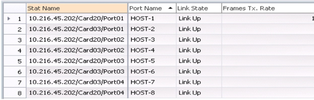
As you did before, start sending multicast traffic from Host-1 at 10 pps (packets per second) for group 225.1.1.1 in VLAN-101. On Host-6 and Host-3, start receivers for the multicast group, 225.1.1.1 on both VLAN-101 and VLAN-102.
You can see from the RT statistics in Figure 11 that, just as before, the traffic sent by Host-1 at 10 pps is now received by the interested receivers, Host-6 and Host-3, and the legacy device, Host-7, in both VLAN-101 and VLAN-102, thereby resulting in 20 pps of incoming traffic on each of them.
In addition, you can see that the traffic is also received by the interested receiver outside the data center, Host-8, resulting in 10 pps of incoming traffic on Host-8.
Multicast Traffic Outputs - LEAF-1, LEAF-2, LEAF-4, LEAF-5, SPINE-2 (VLAN-101): the traffic forwarding behavior on LEAF-1, LEAF-2, LEAF-3, LEAF-4, SPINE-1, and SPINE-2 remains the same and was skipped for the sake of brevity.
Multicast Traffic Outputs – BL-1, BL-2: As before, BL-1 being PIM DR on irb.102, routes the traffic arriving on irb.101 into irb.102 to serve the VLAN-102 receivers within the DC:
lab@BL-1> show multicast route extensive instance VRF-1
Instance: VRF-1 Family: INET
Group: 225.1.1.1
		Source: 18.18.18.30/32
		Upstream interface: irb.101
		Downstream interface list:
			irb.102
		Number of outgoing interfaces: 1
		Session description: Unknown
		Statistics: 1 kBps, 10 pps, 917043 packets
		Next-hop ID: 131102
		Upstream protocol: PIM
		Route state: Active
		Forwarding state: Forwarding
		Cache lifetime/timeout: 360 seconds
		Wrong incoming interface notifications: 33
		Uptime: 00:03:15
Since the external receiver interest is notified to BL-2 via the PIM Join in the M-VLAN, VLAN-1000, BL-2 routes the traffic arriving on irb.101 into irb.1000 (i.e. VLAN-1000):
lab@BL-2> show multicast route extensive instance VRF-1
Instance: VRF-1 Family: INET
Group: 225.1.1.1
		Source: 18.18.18.30/32
		Upstream interface: irb.101
		Downstream interface list:
			irb.1000
		Number of outgoing interfaces: 1
		Session description: Unknown
		Statistics: 1 kBps, 10 pps, 1970 packets
		Next-hop ID: 131108
		Upstream protocol: PIM
		Route state: Active
		Forwarding state: Forwarding
		Cache lifetime/timeout: 310 seconds
		Wrong incoming interface notifications: 2
		Uptime: 00:04:32
EVPN Inter-VLAN Multicast Routing with Optimization chapter showed what happens to the traffic routed in VLAN-102 by BL-1. So now, let’s look at what happens to the traffic routed to irb.1000 by BL-2.
The traffic routed into VLAN-1000 is sent out on the access interface, ae0 towards the PIM-GW:
lab@BL-2> show interfaces ae0 extensive
…
Logical interface ae0.0 (Index 573) (SNMP ifIndex 568) (Generation 215)
 Flags: Up SNMP-Traps 0x24024000 Encapsulation: Ethernet-Bridge
 Statistics	Packets	pps	Bytes	bps
 Bundle:
Input :		6376	0	450534	296
Output:		4926	11	423788	6328
…
Multicast Traffic Outputs – PIM-GW
PIM-GW routes the traffic arriving on irb.1000 onto its interface, ge-0/0/1.0, towards the PIM-RP:
lab@PIM-GW> show multicast route extensive
Instance: master Family: INET
Group: 225.1.1.1
		Source: 18.18.18.30/32
		Upstream interface: irb.1000
		Downstream interface list:
 			ge-0/0/1.0
		Number of outgoing interfaces: 1
		Session description: Unknown
		Statistics: 1 kBps, 10 pps, 415 packets
		Next-hop ID: 1048577
		Upstream protocol: PIM
		Route state: Active
		Forwarding state: Forwarding
		Cache lifetime/timeout: 360 seconds
		Wrong incoming interface notifications: 0
		Uptime: 00:00:41
Multicast Traffic Outputs – PIM-RP
PIM-RP routes the traffic received from PIM-GW onto its interface, ge-0/0/1.0, towards the external receiver, HOST-8:
lab@PIM-RP> show multicast route extensive
Instance: master Family: INET
Group: 225.1.1.1
		Source: 18.18.18.30/32
		Upstream interface: ge-0/0/0.0
		Downstream interface list:
			ge-0/0/1.0
		Number of outgoing interfaces: 1
		Session description: Unknown
		Statistics: 1 kBps, 10 pps, 323 packets
		Next-hop ID: 1048578
		Upstream protocol: PIM
		Route state: Active
		Forwarding state: Forwarding
		Cache lifetime/timeout: 360 seconds
		Wrong incoming interface notifications: 1
		Uptime: 00:00:33
Receiver Within the DC and Source Outside the DC
Now let’s look at the case where the source is outside the DC.
We will stop all sources and receivers that have been previously started, and you should, too, in your own lab.
Now start sending multicast traffic from Host-8 at 10 pps for group 225.1.1.1. As before, on Host-6 and Host-3, start receivers for the multicast group, 225.1.1.1 on both VLAN-101 and VLAN-102.
Traffic Statistics on RT
From the RT statistics, you can see that the traffic sent by Host-8 at 10 pps is received by the interested receivers, Host-6 and Host-3, and the legacy device, Host-7, in both VLAN-101 and VLAN-102 thereby resulting in 20 pps of incoming traffic on each of them.
Multicast Traffic Outputs – PIM-RP
PIM-RP routes the traffic received on interface ge-0/0/1.0 from HOST-8 onto its interface, ge-0/0/0.0, towards PIM-GW.
Multicast Traffic Outputs – PIM-GW
PIM-GW routes the traffic received on interface ge-0/0/1.0 from PIM-RP onto its interface, irb.1000 (VLAN-1000), towards the DC.
The traffic routed into VLAN-1000 will be forwarded on the interface ae0 and will be load balanced towards BL-1 or BL-2. In our case, we see that it is load balanced on interface ge-0/0/2 towards BL-2:
lab@PIM-GW> show interfaces ae0 extensive
…
Logical interface ae0.0 (Index 337) (SNMP ifIndex 563) (Generation 146) Flags: Up SNMP-Traps 0x24024000 Encapsulation: Ethernet-Bridge
Statistics
Bundle:	Packets	pps	Bytes	bps
Input :	4481	0	278030	336
Output:	7348	10	364552	3960
…
Link:
ge-0/0/0.0
Input :	0	0	0	0
Output:	0	0	0	0
ge-0/0/2.0
Input :	4481	0	278030	336
Output:	7348	10	364552	3960
…
Multicast Traffic Outputs – BL-1, BL-2
BL-2 switches the external multicast traffic arriving on the access interface, ae0 in the MVLAN, VLAN- 1000 towards BL-1. In addition, being PIM DR on irb.101, BL-2 also routes the traffic arriving on irb.1000 into irb.101 to serve the VLAN-101 receivers within the DC:
lab@BL-2> show multicast route extensive
instance VRF-1 Instance: VRF-1 Family: INET
Group: 225.1.1.1 Source: 21.21.21.2/32
		Upstream interface: irb.1000
		Downstream interface list:
			irb.101
		Number of outgoing interfaces: 1
		Session description: Unknown
		Statistics: 1 kBps, 10 pps, 6808 packets
		Next-hop ID: 131070
		Upstream protocol: PIM
		Route state: Active
		Forwarding state: Forwarding
		Cache lifetime/timeout: 360 seconds
		Wrong incoming interface notifications: 0
		Uptime: 00:15:23
BL-1, receives the external multicast traffic forwarded by BL-2 on the VTEP in the M-VLAN (VLAN- 1000, irb.1000). Since the traffic arrives from the core, it is not sent back to the core (CORE-IMET-SKIP). Local bias procedures (DST-LOCAL-BIAS) prevent the traffic from being sent back on the access interface, ae0 towards the PIM-GW.
Being PIM DR on irb.102, BL-1 routes the traffic arriving on irb.1000 into irb.102 to serve the VLAN-102 receivers within the DC:
lab@BL-1> show multicast route extensive
instance VRF-1 Instance: VRF-1 Family: INET
Group: 225.1.1.1
		Source: 21.21.21.2/32
		Upstream interface: irb.1000
		Downstream interface list:
			irb.102
		Number of outgoing interfaces: 1
		Session description: Unknown
		Statistics: 1 kBps, 10 pps, 6408 packets
		Next-hop ID: 1310890
		Upstream protocol: PIM
		Route state: Active
		Forwarding state: Forwarding
		Cache lifetime/timeout: 360 seconds
		Wrong incoming interface notifications: 0
		Uptime: 00:15:30
The external multicast traffic thus routed into VLAN-101 (by BL-2) and VLAN-102 (by BL-1) is optimally switched in the data center with the help of AR and SMET procedures. We did detailed verifications for this in EVPN Inter-VLAN Multicast Routing with Optimization chapter. The verification of this flow is therefore left as an exercise for the reader.
Here we also see the advantage of the DR-Priority configuration we completed earlier in sharing the load of routing the multicast traffic into different customer VLANS, between the two BORDER-LEAF devices.
Detailed Control Plane Verification
Receiver Outside the DC and Source Within the DC
Verify that the PIM-GW sends the (S,G) PIM Join towards one of the border leaf PEs in order to pull traffic from the data center for the external receiver. In our case, the Join is being sent towards BL-2 via irb.1000:
lab@PIM-RP> show pim join extensive 225.1.1.1 source 18.18.18.30
Group: 225.1.1.1
		Source: 18.18.18.30
		Flags: sparse,spt
		Upstream interface: irb.1000
		Upstream neighbor: 30.30.30.2 (assert winner)
		Upstream state: Join to Source, Prune to RP
		Keepalive timeout:
		Uptime: 00:00:43
		Downstream neighbors:
			Interface: ge-0/0/1.0 (assert winner)
				20.20.20.2 State: Join Flags: S Timeout: 167
				Uptime: 00:00:43 Time since last Join: 00:00:43
				Assert Winner: 20.20.20.1 Metric: 2 Pref: 10 Timeout: 42
…
Verify that, BL-2 alone builds PIM (S,G) state with PIM-RP in its downstream interface list:
lab@BL-2> show pim join extensive 225.1.1.1 source 18.18.18.30
Group: 225.1.1.1
		Source: 18.18.18.30
		Flags: sparse,spt
		Upstream interface: irb.101
		Upstream neighbor: Direct
		Upstream state: Local Source, Prune to RP
		Keepalive timeout: 335
		Uptime: 00:01:07
		Downstream neighbors:
			Interface: irb.101
				18.18.18.2 State: Join Flags: S Timeout: Infinity
				Uptime: 00:01:07 Time since last Join: 00:01:07
			Interface: irb.1000 (assert winner)
				30.30.30.10 State: Join Flags: S Timeout: 203
				Uptime: 00:01:07 Time since last Join: 00:00:07
				Assert Winner: 30.30.30.2 Metric: 0 Pref: 0 Timeout: 17
			Number of downstream interfaces: 2
			Number of downstream neighbors: 2

lab@BL-1> show pim join extensive 225.1.1.1 source 18.18.18.30
Group: 225.1.1.1
		Source: 18.18.18.30
		Flags: sparse,spt
		Upstream interface: irb.101
		Upstream neighbor: Direct
		Upstream state: Local Source, Local RP
		Keepalive timeout: 345
		Uptime: 00:00:55
		Downstream neighbors:
			Interface: irb.102
				19.19.19.2 State: Join Flags: S Timeout: Infinity
 			Uptime: 00:01:07 Time since last Join: 00:00:55
		Number of downstream interfaces: 1
		Number of downstream neighbors: 1
Receiver Within the DC and Source Outside the DC
Verify that BL-1 and BL-2 send (*, G) and (S,G) PIM Joins towards PIM-GW on behalf the receivers within the DC:
lab@BL-2> show pim join extensive 225.1.1.1 star-g instance VRF-1
Instance: PIM.VRF-1 Family: INET
R = Rendezvous Point Tree, S = Sparse, W = Wildcard
Instance: PIM.VRF-1 Family: INET
R = Rendezvous Point Tree, S = Sparse, W = Wildcard
Group: 225.1.1.1
		Source: *
		RP: 111.111.111.111
		Flags: sparse,rptree,wildcard
		Upstream interface: irb.1000
		Upstream neighbor: 30.30.30.10
		Upstream state: Join to RP
		Uptime: 00:15:24
		Downstream neighbors:
			Interface: irb.101
				18.18.18.2 State: Join Flags: SRW Timeout: Infinity
				Uptime: 00:14:07 Time since last Join: 00:14:07
		Number of downstream interfaces: 1
		Number of downstream neighbors: 1
lab@BL-2> show pim join extensive 225.1.1.1 source 21.21.21.2 instance VRF-1
Instance: PIM.VRF-1 Family: INET
R = Rendezvous Point Tree, S = Sparse, W = Wildcard
Group: 225.1.1.1
		Source: 21.21.21.2
		Flags: sparse,spt
		Upstream interface: irb.1000
		Upstream neighbor: 30.30.30.10
		Upstream state: Join to Source, No Prune to RP
		Keepalive timeout: 310
		Uptime: 00:15:23
		Downstream neighbors:
			Interface: irb.101
				18.18.18.2 State: Join Flags: S Timeout: Infinity
				Uptime: 00:14:07 Time since last Join: 00:14:07
		Number of downstream interfaces: 1
		Number of downstream neighbors: 1