
Deploy Juniper Security Director Using an ARM Template on Microsoft Azure
This topic guides you through the Juniper Security Director VM deployment using an Azure Resource Manager (ARM) template on the Azure portal.
Before You Begin
-
You must have an active Azure subscription with appropriate Role-Based Access Control (RBAC).
-
Create a resource group and configure a VNet in your resource group with at least one subnet. For more information, refer Microsoft Azure documentation.
-
For VM sizing details, see Juniper Security Director System Requirements for Microsoft Azure.
To deploy Juniper Security Director VM using the Azure portal:
Step 1: Download the VHD.tar File and the Software Bundle
-
Download the Juniper Security Director VHD (vhd.tar file) from Software Downloads page to a webserver or your local machine.
- Download the Juniper Security Director software bundle (.tgz file) from Software Downloads page to your staging server.
A staging server is an intermediate server where the software bundle is downloaded and is accessible from the VM.
The staging server must support software bundle download from the Juniper Security Director VM using SCP, HTTP, or HTTPS. Before you deploy the VM, you must have the location to the staging server.
Step 2: Deploy the VM
Untar the vhd.tar file using the command:
tar --sparse -xvf
              Juniper-Security-Director-<version-build>-vhd.tar
The tar file includes a Disk 0 (OS disk) VHD file and a JSON file. The JSON file is the custom ARM template to deploy the VM.
Upload the Disk 0 VHD file to your storage account using the command:
azcopy copy
              output-artifacts/Juniper-Security-Director-<version-build>/vhd/Juniper-Security-Director-<version-build>-disk-0.vhd
              'https://dest.blob.core.windows.net/.../Juniper-Security-Director-<versionbuild>-
              disk-0.vhd${Azure_Storage_Account_SAS_TOKEN}' --blob-type=PageBlob
              --overwrite=true
Save the disk-0.vhd storage account URL. You will need it to create the image in Step 6.
Log in to the Microsoft Azure portal.
In the search bar, type images and select Images from the list.
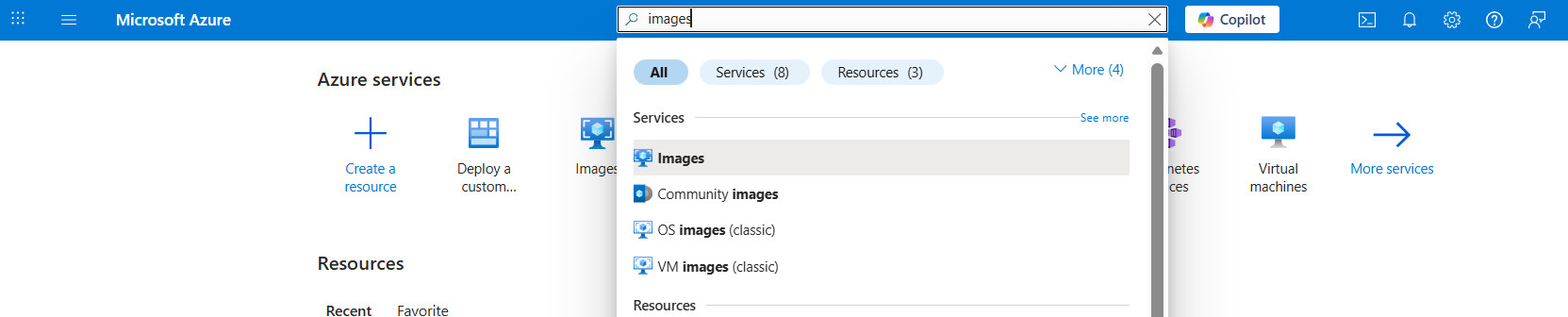
The Computer infrastructure/Custom images page is displayed.
Click the create icon (
 ) to create an image.
The Create an image page is displayed.
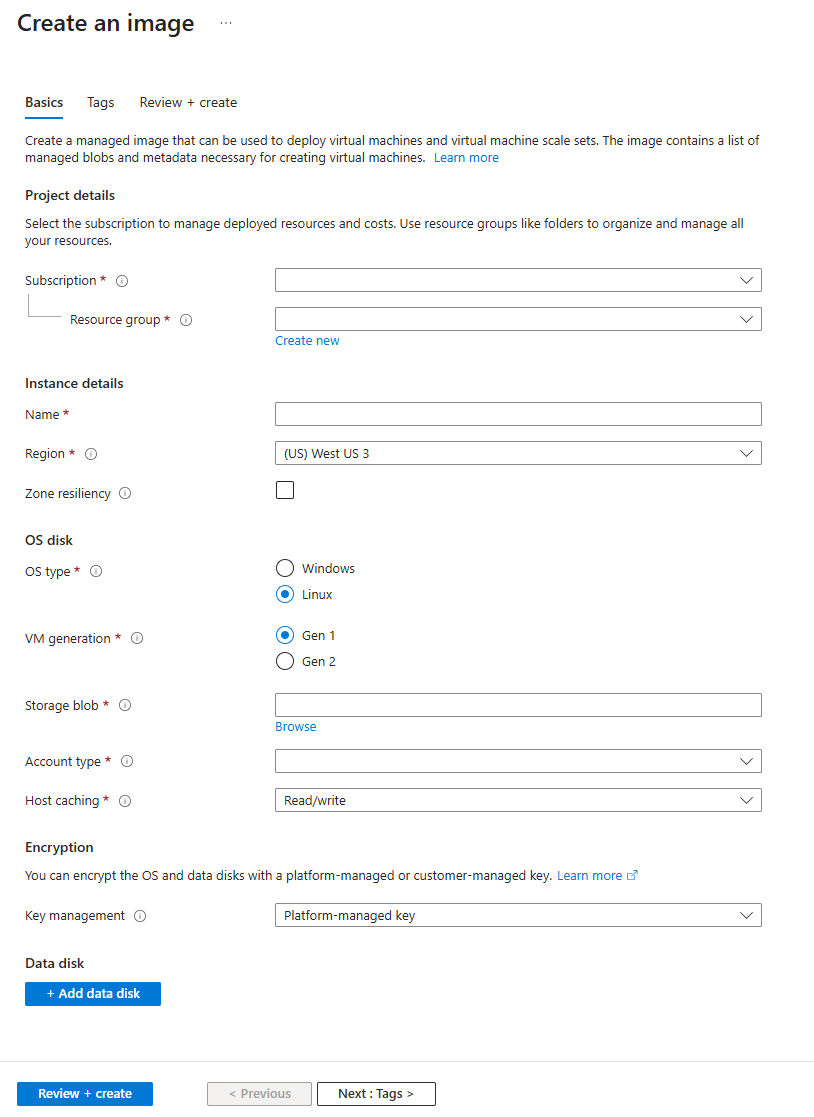
Enter the details as mentioned in Table 1 and click Review + create.
Table 1: Create an Image Field Description Subscription Select your Azure service subscription. Resource group Create a resource group or select an existing one. Instance DetailsName Enter the name of the image. Region Enter the Azure region into which the resource should be deployed. Zone Resiliency Enable the check box if you want your image to remain available even during zone failures. OS DiskOS type Select the OS type as Linux. VM generation Select the VM generation as Gen 1. Storage blob Enter or browse the uploaded disk 0 (.vhd) file storage account location. Account Type Select a desired option from the drop-down list Host caching Select Read/write from the drop-down list. EncryptionKey Management Select a desired option from the drop-down list. The image created is displayed on the Custom images page.
In the search bar, type deploy and select Deploy a custom template.
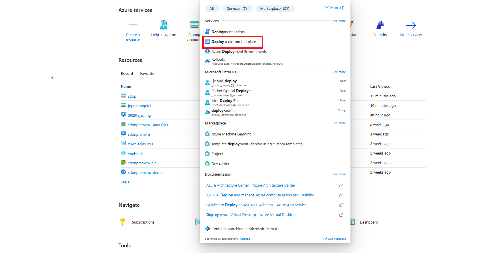
The Custom deployment page is displayed.
Click Build your own template in the editor.
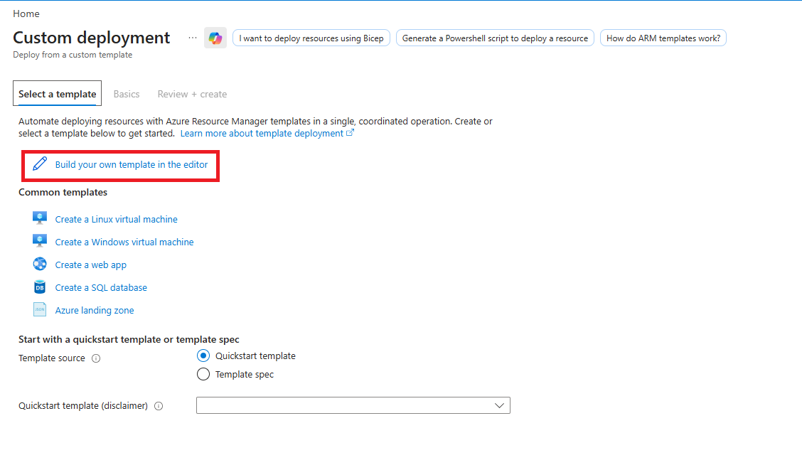
The Edit template page is displayed with the default template.
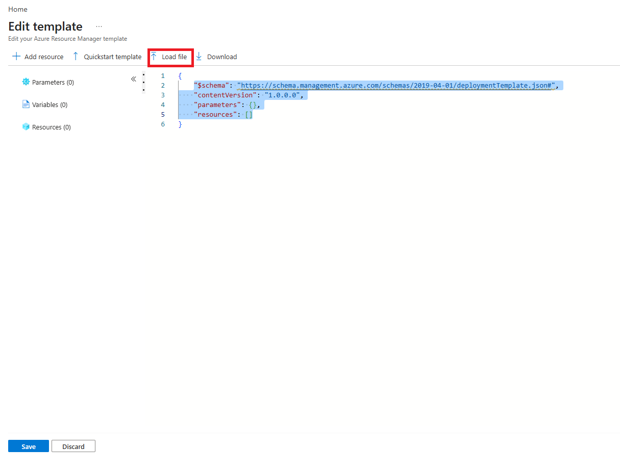
Replace the default template with the custom template.
Copy and paste the content of JSON file on the Edit template page or Click Load file to upload the JSON file generated when you extracted the .vhd file in Step 1.
Click Save.
The Custom deployment page is displayed.
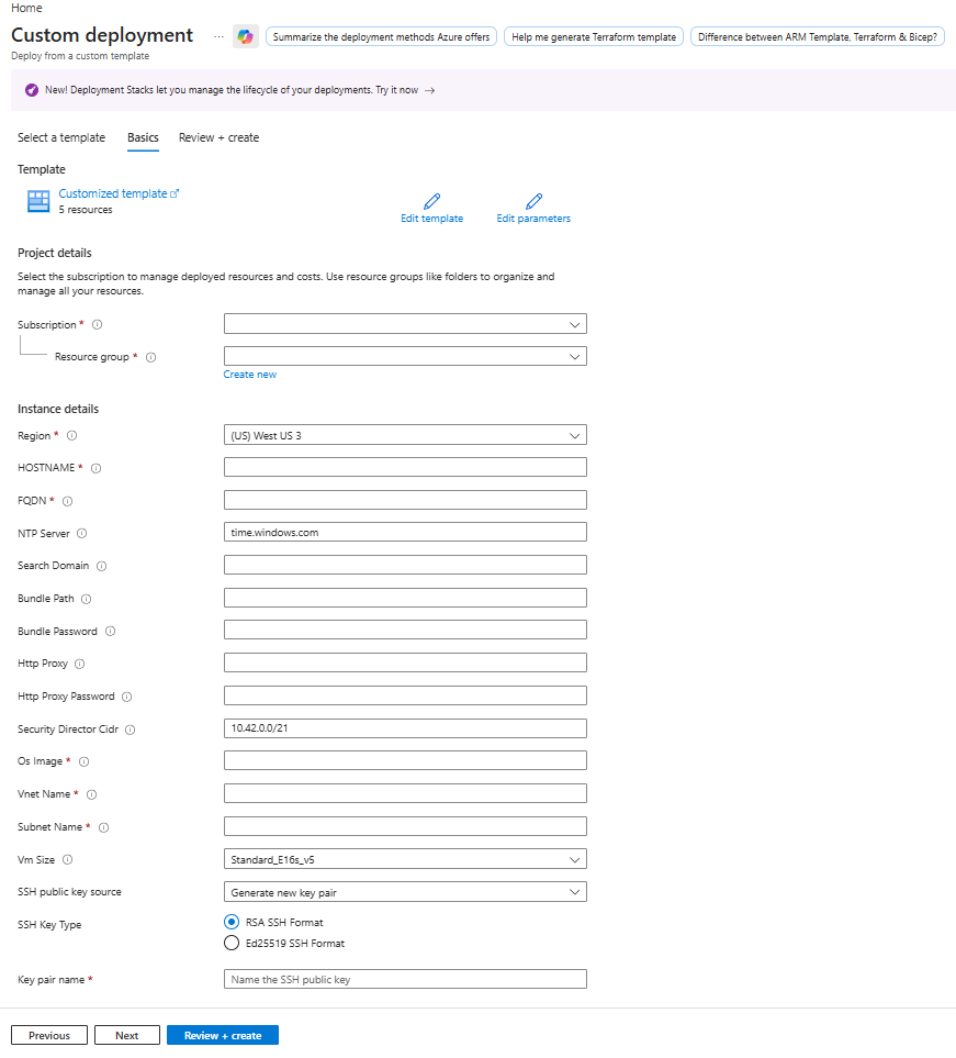
Enter the custom values as described in Table 2 and click Review+create.
Table 2: Custom Deployment Page Field Description Subscription Select your subscription to manage deployed resources. Resource group Select a resource group or click Create new to create a unique resource group. Instance detailsRegion Choose the Azure region based on your requirement. Hostname Enter the hostname for the VM. FQDN Enter the FQDN. NTP Server Enter the NTP server address. Default value is time.windows.com. Search Domain Enter the DNS search domain Bundle path Enter the location of the software bundle (.tgz file). You can enter the SCP, HTTP, or HTTPS path. Bundle password Enter the password to access the bundle URL if download authentication is required. HTTP Proxy Enter the HTTP proxy URL to use for the software bundle (.tgz file) download, if required. HTTP Proxy Password Enter the password to access the software bundle (.tgz file) URL if download authentication is required Security Director CIDR Enter the CIDR for the Juniper Security Director access. Security Director CIDR is the IP address range that Kubernetes will use for the internal service or pod networking when deploying and running Security Director On-Premises services.
Default—10.42.0.0/21
Requirement—The CIDR must be /21 or larger (for example,
10.42.0.0/21,10.42.0.0/20).
This CIDR must not overlap with the VM management subnet, to avoid routing/IP conflicts between the Kubernetes network and the management network used by the VMs.
OS Image Enter the Azure resource ID of the created image. Vnet name Enter the name of the virtual network. Subnet name Enter the name of the subnet. VM size Select the VM size. SSH Public Key Source Select an SSH public key source from the drop-down list. Based on your selection, corresponding fields are populated. Enter the required inputs.
Review the details and click Create.
After the VM is deployed, Your Deployment is Complete message is displayed.
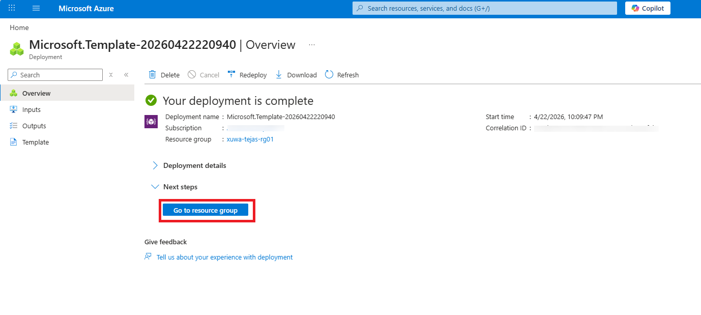
Click Deployment details to view the VM information.
Click Go to resource group.
The Resource Overview page is displayed.
Click the VM name to open the VM Overview page.
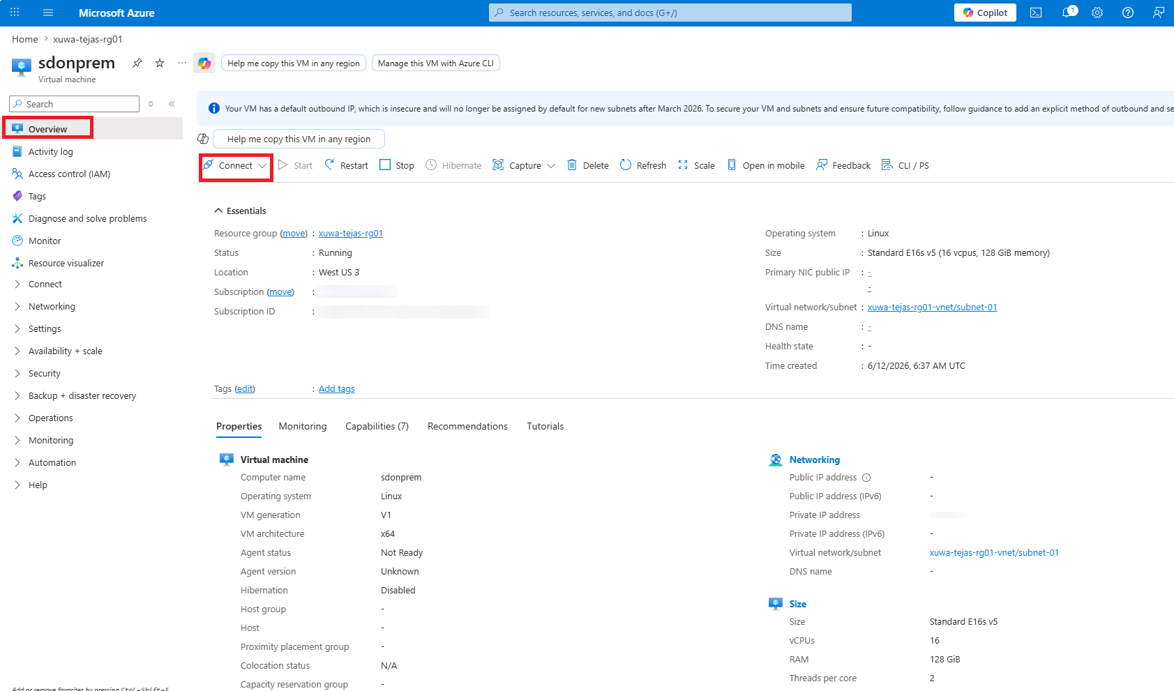
Select .
Click .
A warning message is displayed. Click the message to enable boot diagnostics.
Select Enable with custom storage account.
Select the Diagnostics storage account or create one.
Click Apply.
Boot diagnostics is successfully enabled for your VM.
Monitor the installation progress through the serial console. After deployment is complete, the console displays the IP address or FQDN needed to log in to the UI.
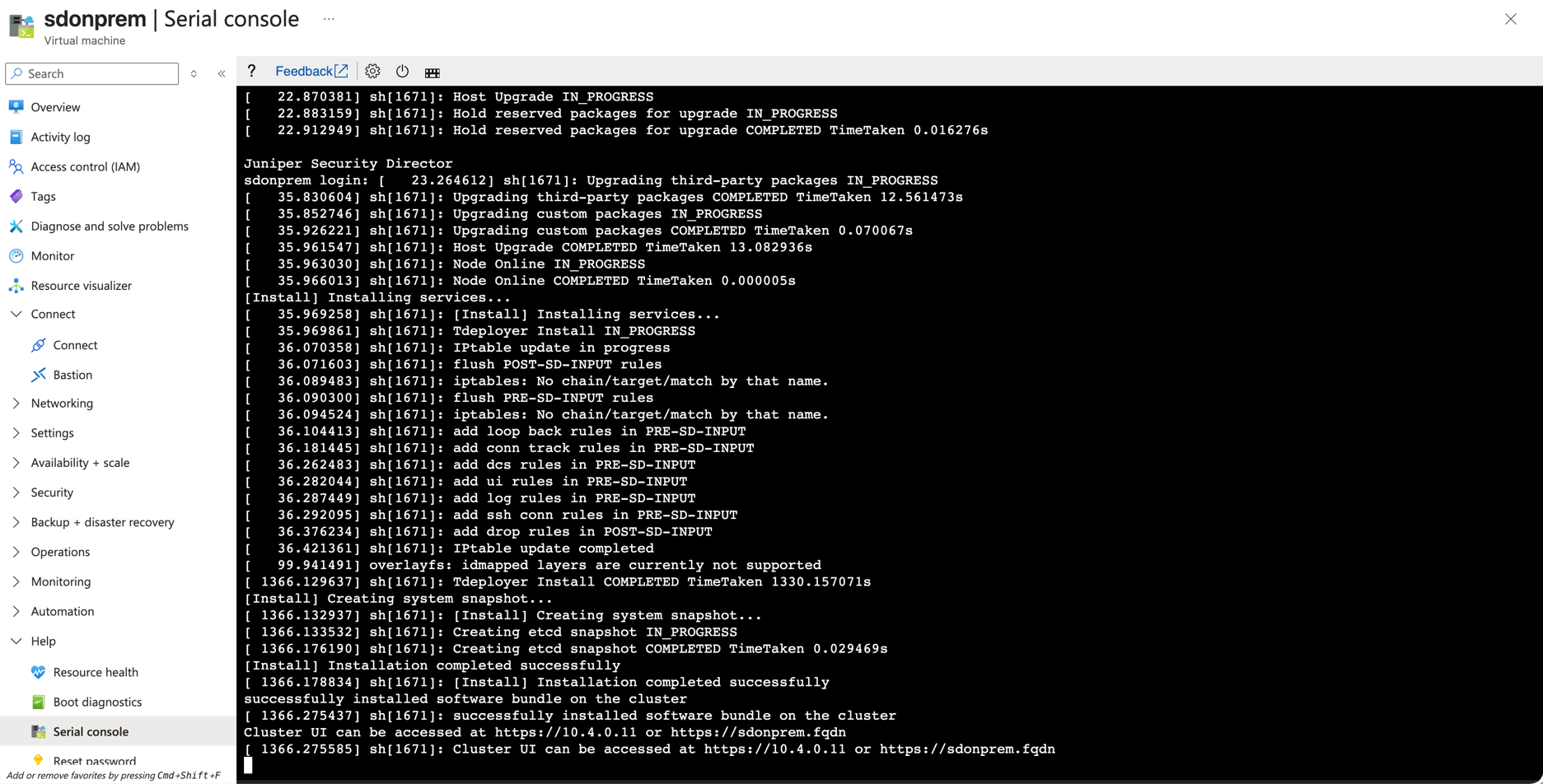
A successful installation requires approximately 50 minutes. If the installation lasts longer, check the VM console for potential errors.
Alternatively, you can
sshto the VM private IP using the cliadmin user and the SSH public key you configured during the deployment. Then, use theshow bundle install statuscommand to check the installation status. On successful installation, Node installation completed successfully message is displayed.Use the
show proxy configcommand to verify that the UI connectivity has been set up correctly.