ON THIS PAGE
Install and Configure Junos Space, Security Director, and Log Collector
Install and Configure SRX Series, EX Series, and QFX Series Devices
Install and Configure Microsoft Windows Server and Active Directory
Download, Deploy, and Configure Policy Enforcer Virtual Machine
Obtain an ATP Cloud license and Create an ATP Cloud Web Portal Account
Install Root CA on the ATP Cloud Supported SRX Series Devices
Download, Deploy, and Configure the ForeScout CounterACT Virtual Machine
Configure the Policy Enforcer Connector for Third-Party Switches
Use Case Implementation: Juniper Connected Security Automated Threat Remediation with ForeScout CounterACT and Juniper Networks Devices
This use case shows how to integrate and configure a ForeScout CounterACT security appliance, a Windows 7 supplicant, a Juniper Networks vSRX virtual firewall, a Juniper Networks EX4300 switch, and a Juniper Networks QFX series switch into a Juniper Connected Security.
To implement this use case for threat remediation (block or quarantine) of infected hosts with ForeScout CounterACT, perform the following required set of installation, configuration, and verification steps:
Requirements
This use case uses the following hardware and software components:
vSRX virtual firewall running Junos OS Release 15.1X49-D110.4 or later
a QFX series switch running Junos OS Release 15.1X53-D60.4 or later
an EX4300 switch running Junos OS Release 15.1R5.5 or later
Advanced Threat Prevention Cloud (ATP Cloud)
Junos Space Network Management Platform, Release 17.2R1 or later
Junos Space Security Director, Release 17.2R2 or later
Log Collector, Release 17.2R2 or later
Policy Enforcer, Release 17.2R2 or later
ForeScout CounterACT version 7.0.0-513-2.3.0-1605
A virtual machine (VM) running Windows 7 with 2x dual NIC hosts
For a list of supported devices, please refer to the Policy Enforcer Release Notes.
Use Case Topology
The use case topology is illustrated in Figure 1
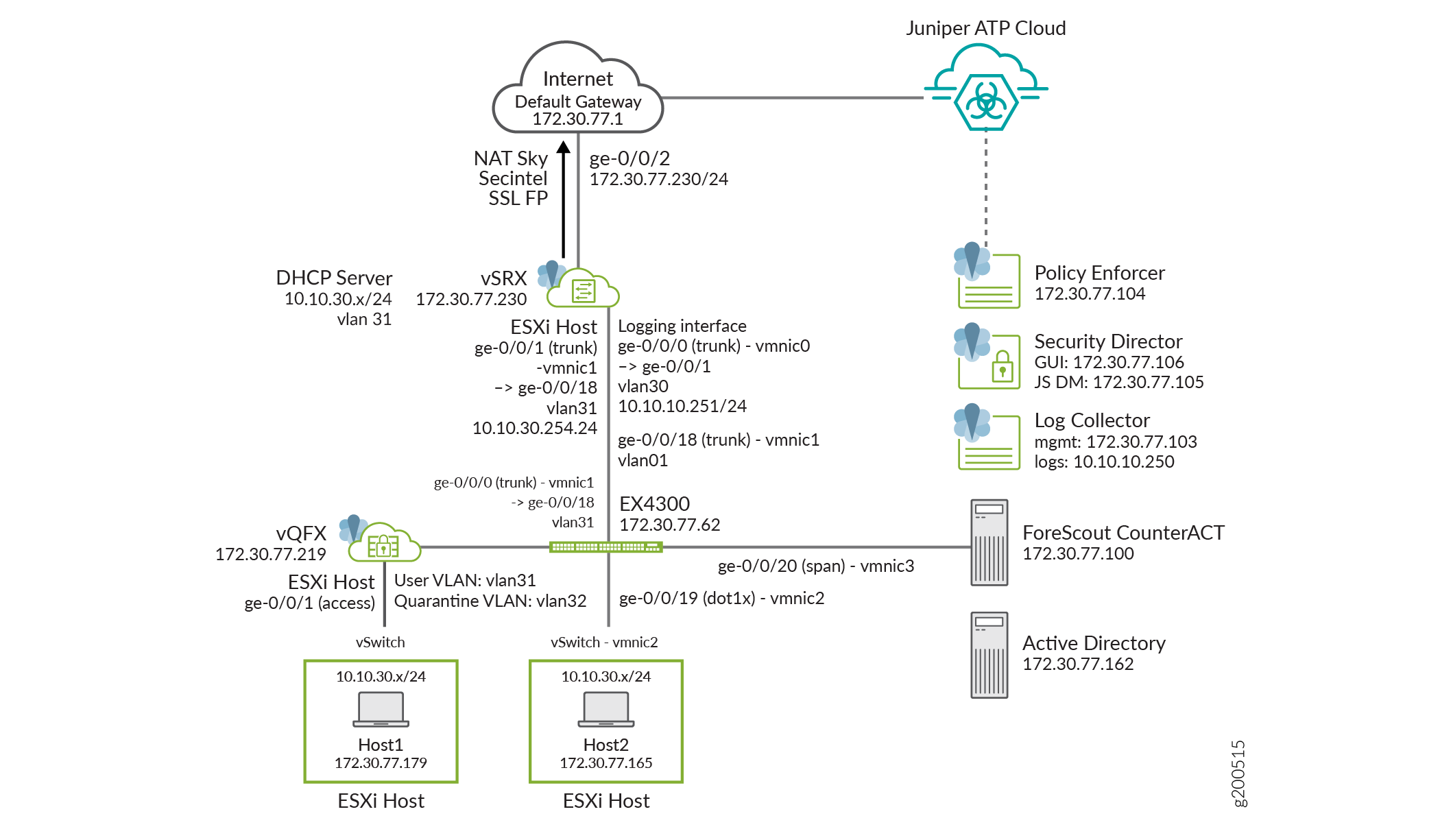
The Forescout CounterACT security appliance applies an agentless approach to network security and integrates with Juniper Connected Security to block or quarantine infected hosts on Juniper Networks’ devices, third-party switches, and wireless access controllers that support and do not support 802.1X protocol integration.
In this use case, the infected end user is quarantined into the user vlan VLAN31 on the EX4300 switch. The EX4300 switch has enabled ForeScout CounterACT and has 802.1X authentication enabled on ge-0/0/19. The end user authenticates to the network using 802.1X.
The following events occur in this use case:
- The infected endpoint is detected by ATP Cloud.
- Policy Enforcer downloads the infected host feed, and then enforces the infected host policy through CounterACT.
- CounterACT queries the server for endpoint details for the infected host’s IP address.
- CounterACT sends a message to the EX4300 switch, telling it to terminate the session by blocking or quarantining vlan31.
- Enforcement occurs on the EX4300 switch on which the endpoint is authenticated.
- CounterACT inventories the applications, services, and processes running on the device, checks the OS version and registry settings, and verifies the presence of security agents. As a result, a complete profile of the device and its security status is obtained.
Install and Configure Junos Space, Security Director, and Log Collector
This section shows how to install and configure Junos Space, Security Directory, and Log Collector for this use cases. These applications are used in this use case to provide the centralized policy and management application for consistent network security policies.
This section covers the following procedures:
- Install Junos Space, Security Director, and Log Collector
- Configure Basic Junos Space Networking
- Install the required DMI Schemas on Security Director
Install Junos Space, Security Director, and Log Collector
- Download the Junos Space Network Management Platform image from https://www.juniper.net/support/downloads/?p=space#sw.
- Install Junos Space using the instructions at https://www.juniper.net/documentation/en_US/junos-space17.2/information-products/pathway-pages/junos-space-virtual-appliance-pwp.html.
- Install Junos Security Director using the instructions at https://www.juniper.net/documentation/en_US/junos-space17.2/topics/task/multi-task/junos-space-sd-log-collector-installing.html.
- Install Log Collector using the instructions at https://www.juniper.net/documentation/en_US/junos-space17.2/topics/task/multi-task/junos-space-sd-log-collector-installing.html.
Configure Basic Junos Space Networking
To configure basic Junos Space Networking in this use case:
- Configure relevant routes, netmask, gateway, DNS, and NTP so that all components except Log Collector can connect to the Internet.
- Ensure all components are in same time zone.
- Ensure that SSH is enabled.
- Ensure that Security Director can connect to the ATP Cloud server, Policy Enforcer, and all devices.
For additional information on configuring Junos Space, see Junos Space Network Management Platform Documentation.
Install the required DMI Schemas on Security Director
Download and install the correct matching Junos OS schemas to manage the Juniper Networks’ devices:
- Add the DMI schemas for the Juniper Networks’ devices using the instructions at https://www.juniper.net/documentation/en_US/junos-space17.2/platform/topics/task/operational/dmi-schemas-adding-updating.html.
- Ensure that device software version and schema version match for all managed devices (SRX Series and EX Series devices).
Install and Configure SRX Series, EX Series, and QFX Series Devices
To install and configure vSRX virtual firewalls, EX Series switches, and QFX Series switches for this use case:
Install and Configure Microsoft Windows Server and Active Directory
Because ForeScout CounterACT does not have a local user database to use for 802.1X authentication, you must install and configure a Windows Server 2008R2 with Active Directory.
- To set up and configure Windows Server 2008R2, click https://docs.microsoft.com/en-us/iis/install/installing-iis-7/install-windows-server-2008-and-windows-server-2008-r2.
- To set up and configure Active Directory, click https://www.petri.com/installing-active-directory-windows-server-2008.
- Create a user domain account to use later during 802.1X authentication.
Download, Deploy, and Configure Policy Enforcer Virtual Machine
To download, deploy, and configure the Policy Enforcer Virtual Machine:
- Download the Policy Enforcer virtual machine image from http://www.juniper.net/support/downloads/?p=sdpe to the management station where the vSphere client is installed.
- On the vSphere client, select File > Deploy OVF Template from the menu bar.
- Click Browse to locate the OVA file that was downloaded.
- Click Next and follow the instructions in the installation wizard.
- Once the installation is complete, log in to the virtual
machine using
rootandabc123as the username and password, respectively. - Configure the network settings, NTP information, and customer information, and complete the wizard.
For more detailed instructions, see https://www.juniper.net/documentation/en_US/release-independent/policy-enforcer/topics/task/installation/policy-enforcer-vm-config.html.
Identify and Connect Policy Enforcer to Security Director
To identify and connect Policy Enforcer to Security Director:
Obtain an ATP Cloud license and Create an ATP Cloud Web Portal Account
To obtain an ATP Cloud license and create an ATP Cloud Web Portal account:
Install Root CA on the ATP Cloud Supported SRX Series Devices
This section is required only if you are enabling HTTPS inspection as part of a malware profile or threat prevention policy.
This section covers the following topics:
- Generate Root CA Certificate using Junos OS CLI or OpenSSL on a UNIX Device
- Configure a Certificate Authority Profile Group
- Export and Import Root CA Certificate into a Web Browser
Generate Root CA Certificate using Junos OS CLI or OpenSSL on a UNIX Device
Use only one of these options.
To generate a root CA certificate using the Junos OS CLI on the SRX device:
Or
To generate a root CA certificate using OpenSSL on a UNIX device:
Generate a PKI public key or private key pair for a local digital certificate.
% openssl req -x509 -nodes -sha256 -days 365 -newkey rsa:2048 -keyout ssl-inspect-ca.key -out ssl-inspect-ca.crt
Copy the key pair onto the SRX device or devices.
On the SRX device(s), import the key pair.
user@host> request security pki local-certificate load key ssl-inspect-ca.key filename ssl-inspect-ca.crt certificate-id ssl-inspect-ca
Apply the loaded certificate as root-ca in the SSL proxy profile.
user@host> set services ssl proxy profile ssl-inspect-profile root-ca ssl-inspect-ca
Configure a Certificate Authority Profile Group
To configure a Certificate Authority (CA) profile group.
Export and Import Root CA Certificate into a Web Browser
To export and import the Root CA Certificate into a web browser:
Or
If you are using a UNIX device, import the certificate into the browser:
% sudo cp ssl-inspect-ca.crt /usr/local/share/ca-certificates/ ssl-inspect-ca.crt
% sudo update-ca-certificates
Download, Deploy, and Configure the ForeScout CounterACT Virtual Machine
This section covers the following topics:
- Prerequisite Tasks
- Install and Configure CounterACT Software
- Install and Configure CounterACT Plugins
- Configure User Directory Plugin
- Configure Switch Plugin
- Configure 802.1X Plugin
- Configure Windows 7 Supplicant
- Test and Troubleshoot 802.1X Authentication
- Configure Data Exchange Plugin
- Configure Web API Plugin
- Verify Plugins
- Configure Automated Threat Remediation Policies
Prerequisite Tasks
Before you begin this procedure, complete the following tasks:
Install and Configure CounterACT Software
To install and configure ForeScout CounterACT software:
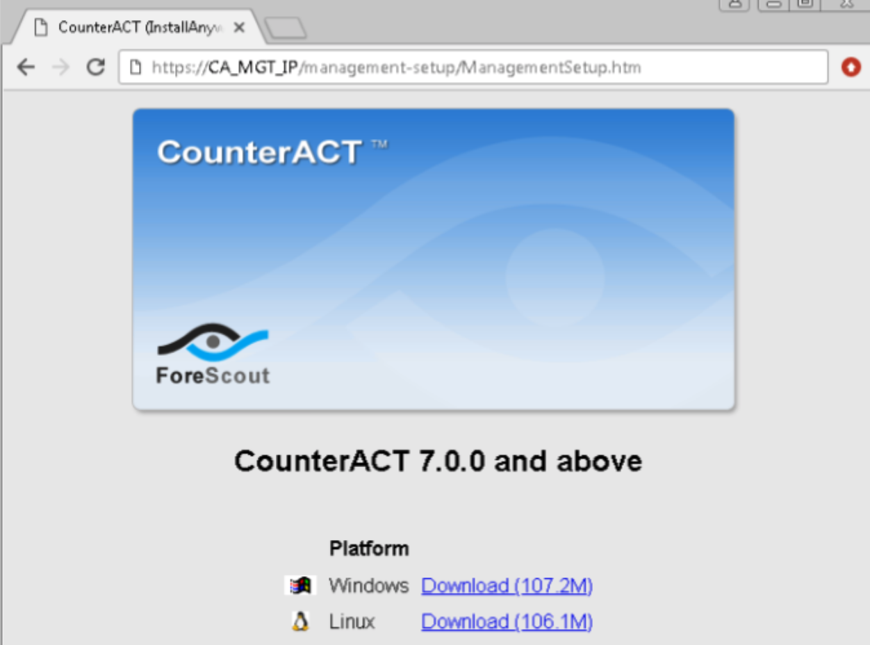
- Use a browser and enter https://pact.ly/S1lnt3 to access and install Juniper CounterACT
product trial software. Enter your credentials to confirm and install
the product trial software.Figure 2: Juniper CounterACT Trial Software Page
Download and install either Windows or Linux for your operating system.
- From the Start menu, select ForeScout CounterACT > CounterACT Console. The CounterACT
Login page appears:Figure 3: CounterACT Login Page
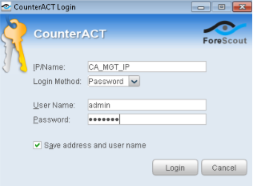
In the IP/Name field, enter the CounterACT device IP name.
From the Login Method list, select Password to perform a standard user authentication.
In the User Name and Password fields, enter your ForeScout username and password.
Click Login.
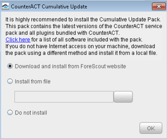
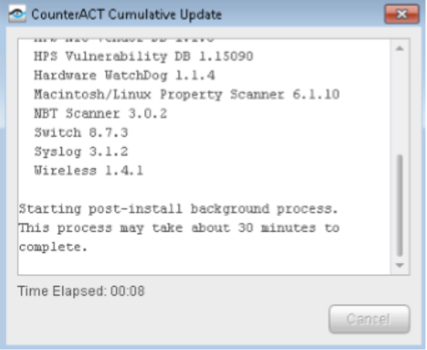
- Download and install the CounterACT cumulative update.Figure 4: CounterACT Cumulative Update
- From the License page, click Install License to install the CounterACT virtual system
license.
Click Next.
Figure 5: License Installation Page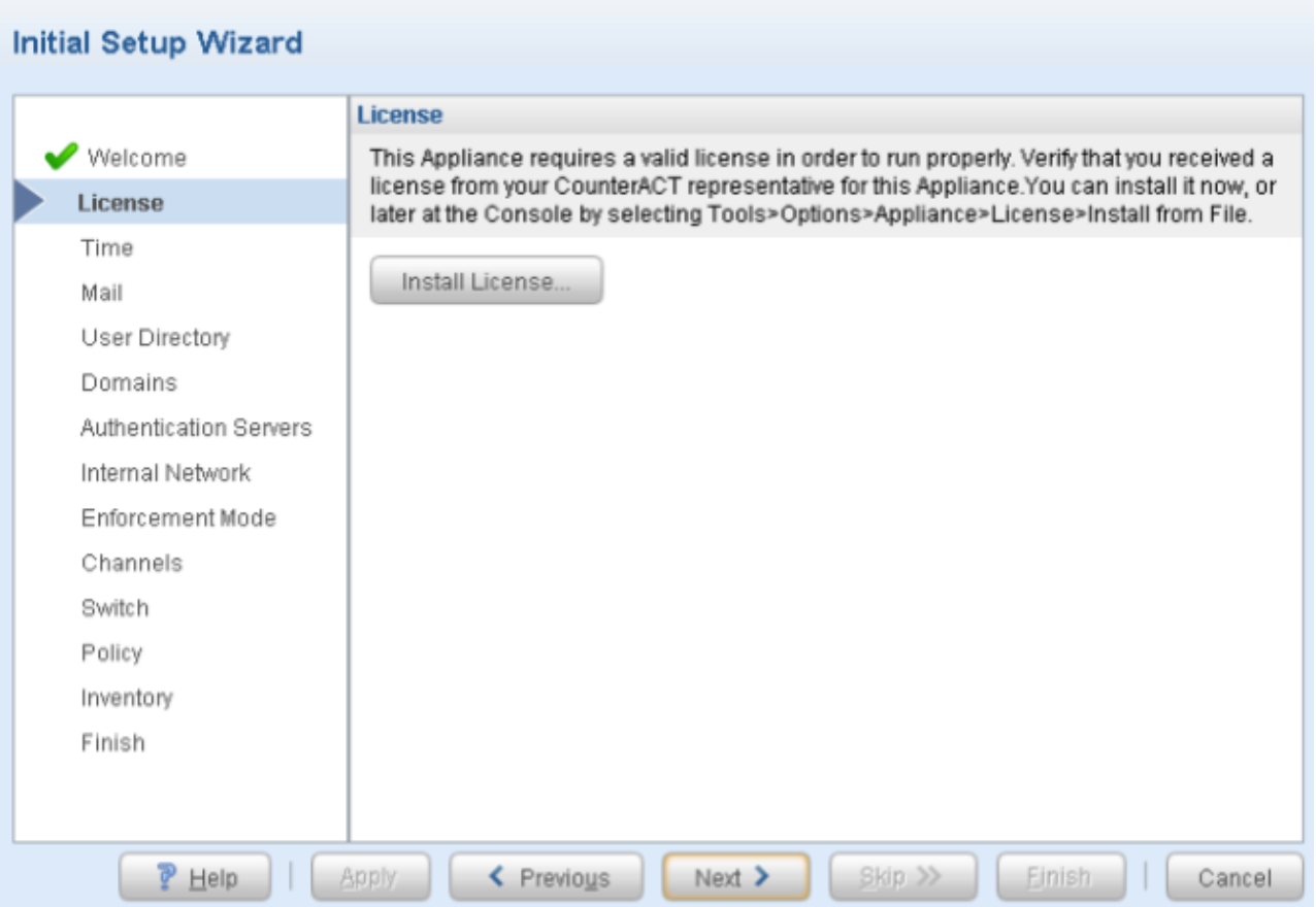
- From the Time page, define the time
settings for your appliance. Figure 6: Time Settings Page
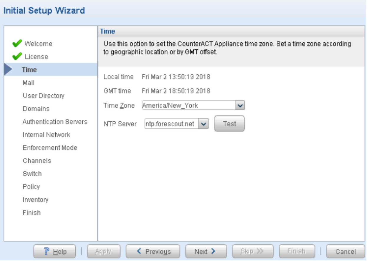
CounterACT devices require NTP connectivity (port 123 UDP) to an NTP server. Enter an NTP server for your organization’s connection, or use the default ForeScout NTP server (ntp.foreScout.net). Click Test to verify that NTP Server returns a successful connection.
Click Next.
- CounterACT generates e-mail messages regarding policy
and threat protection alert, scheduled reports, critical system operation
alerts, and license alerts from the Mail page.Note:
For this use case, do not use the Email Notifications and Alerts option. However, you cannot skip this step, and must enter a dummy e-mail address. Click Next.
Figure 7: Mail Settings Page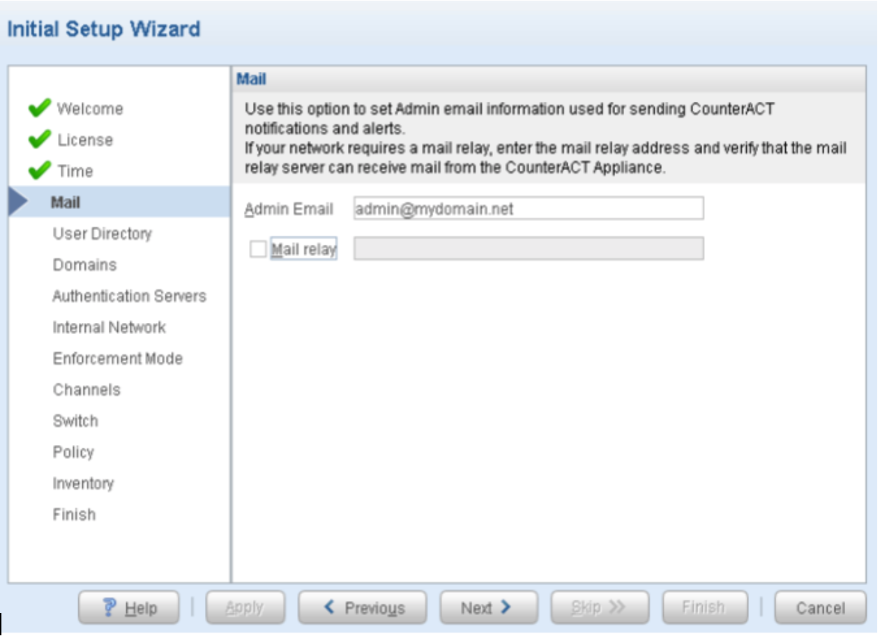
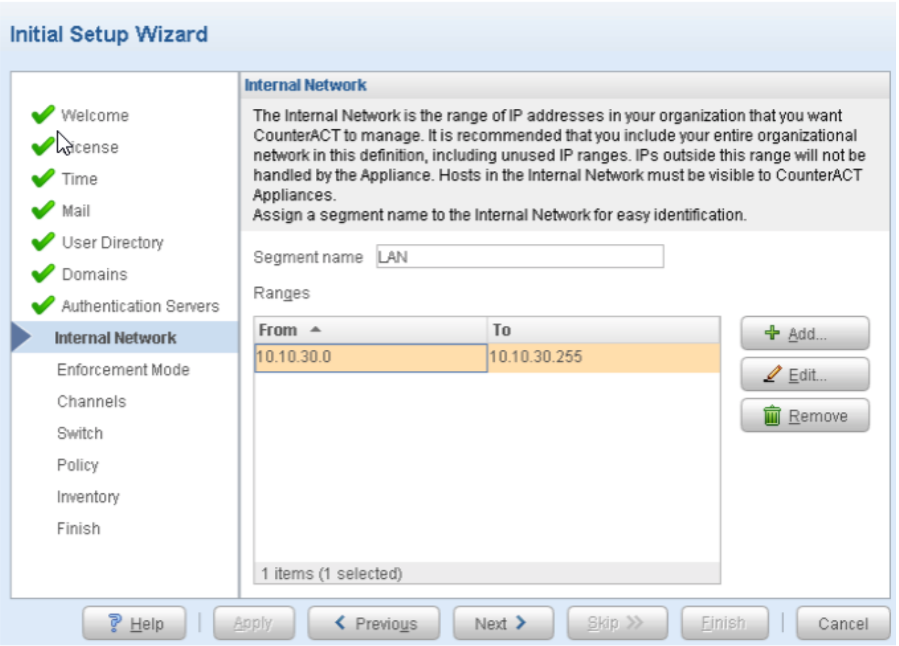
- From the Internal Network page, add
the IP address range (10.10.10.0 to 10.10.30.255) for the internal
network that you want CounterACT to manage. Click Next. Figure 8: Internal Network Settings
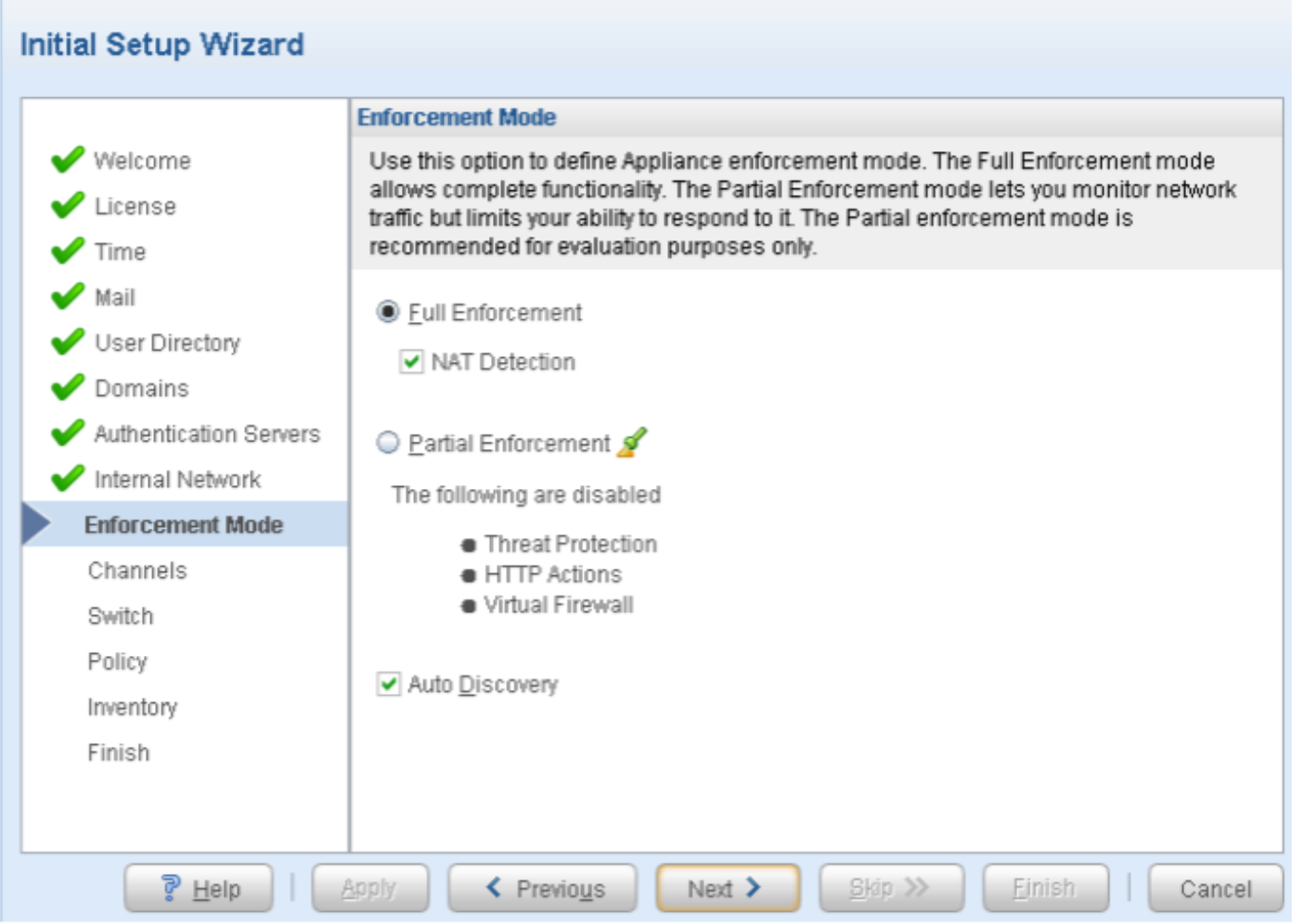
- From the Enforcement Mode page, enable NAT Detection, and accept the other default enforcement
mode settings and click Next.Figure 9: Enforcement Mode Settings
- From the Channels page:
Define a new channel by selecting Add from the Channels list. This channel is used to match the appliance interface connections that detect and respond to traffic on the network interfaces.
From the Monitor list, select eth1 as an interface.
From the Response list, select eth2 as an interface.
Assign both interfaces at the Data Center.
Enable the All VLANs option and verify that the Monitor interface receives the mirrored traffic from the configured EX4300 switch.
Figure 10: Channels Settings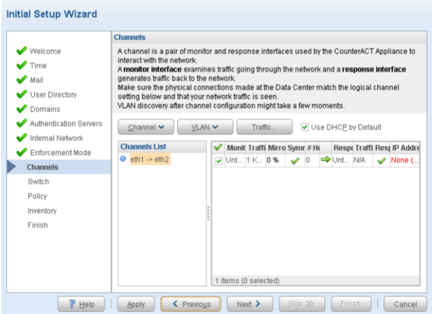
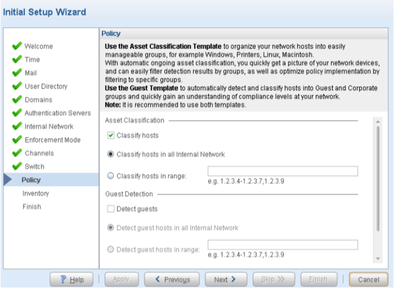
- From the Policy page, accept the
default setting for Classify hosts (enabled)
for Asset Classification. Click Next. Figure 11: Policy Settings
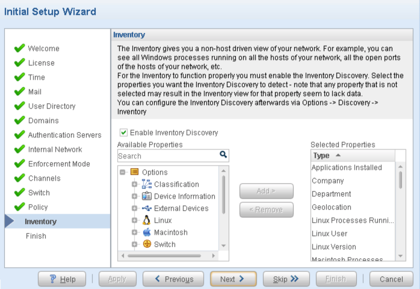
- From the Inventory page, accept the
default setting for Enable Inventory Discovery (enabled). Click Next.Figure 12: Inventory Settings
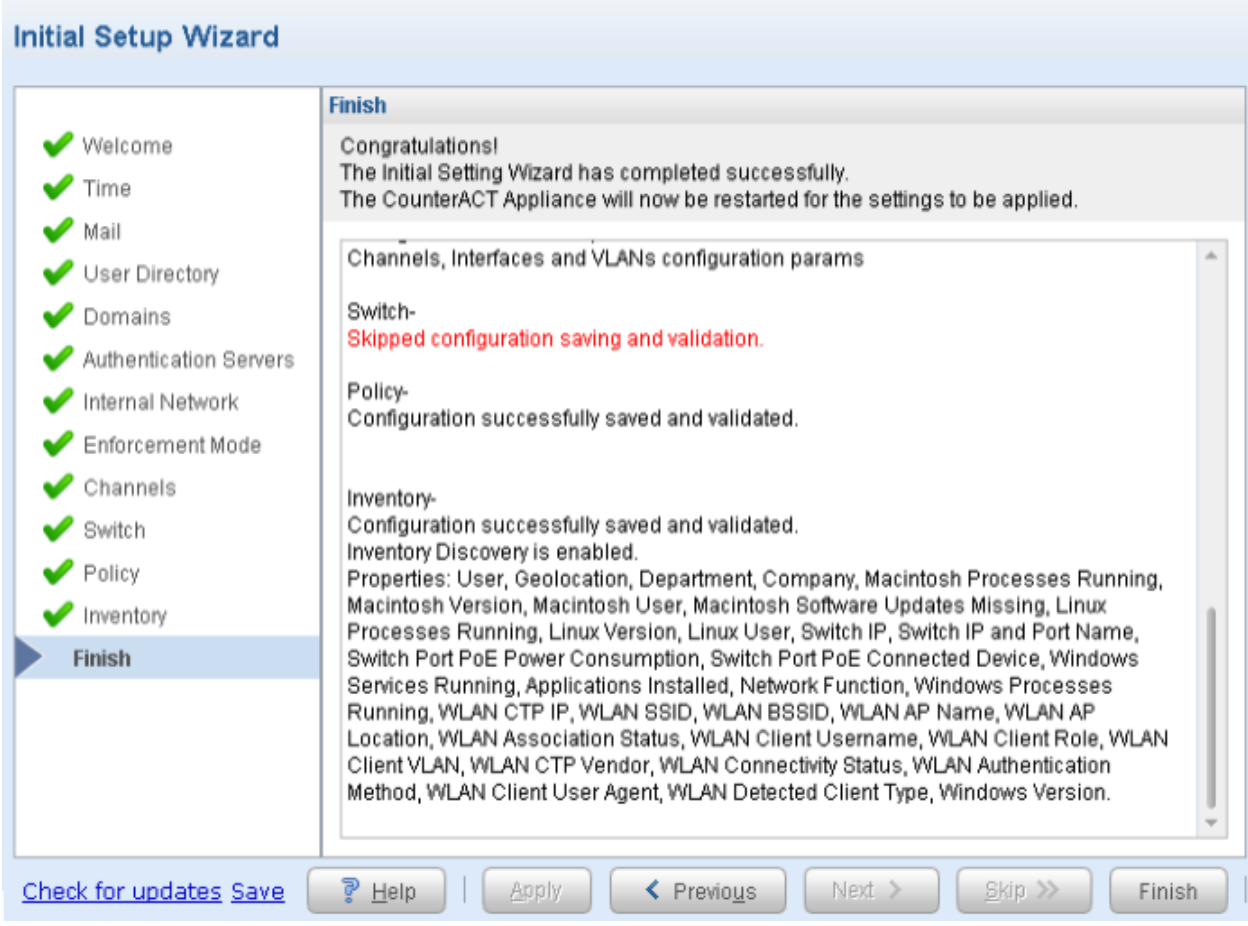
- From the Finish page, review the
wizard configuration summary. Click Finish to
complete the initial setup. Click Save to save
the configuration file to the external file.Figure 13: Finish Initial Setup Page
 Note:
Note:(Optional) To disable the map functionality, select Tools > Options > Map.
- To download and install the updated packages, click Check for updates (or select Tools > Check for
Updates). Figure 14: Check for Updates Screen
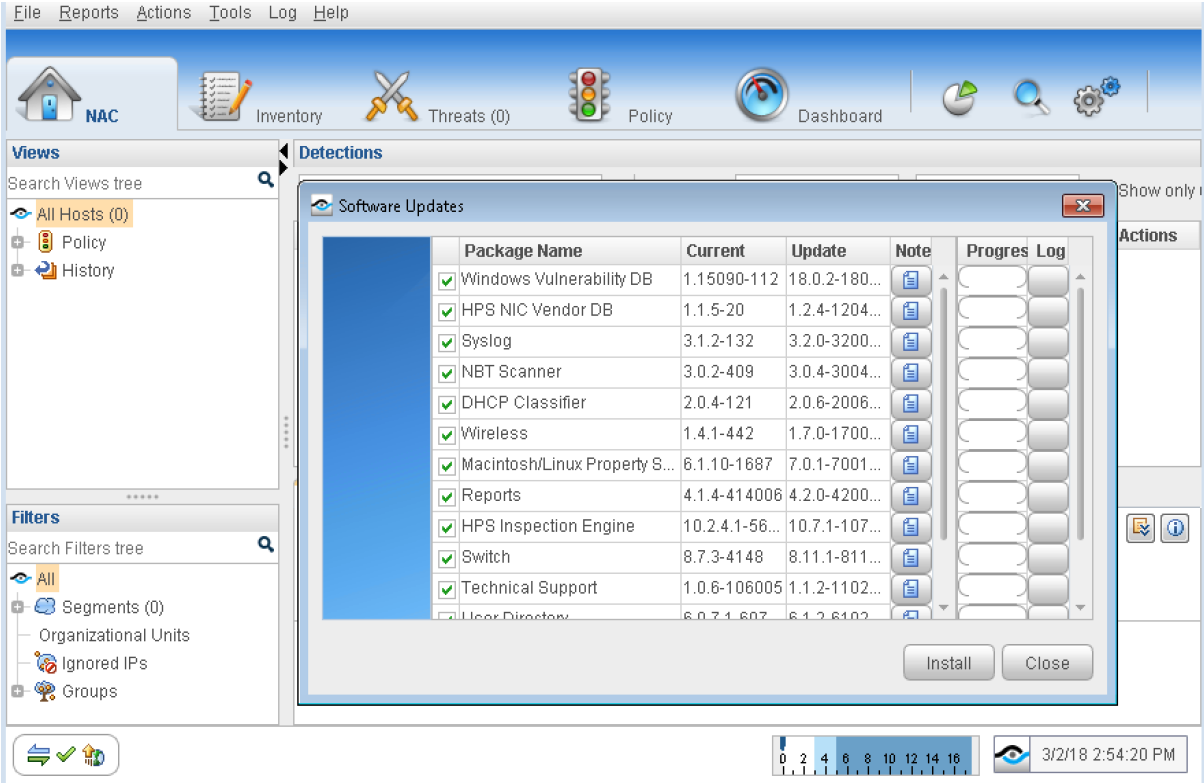
- From the Software Updates page:
Install the Infrastructure Update Pack.
Install the second Service Pack. After the service package installation is complete, CounterACT will automatically restart. Click OK to restart the console.
Figure 15: Service Package Installation Complete Screen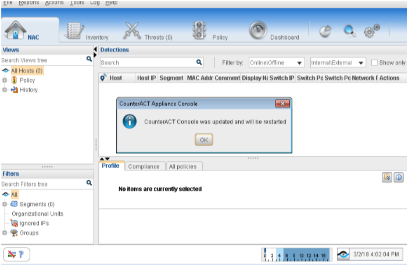
Log in with your credentials.
Click Check for updates (or select Tools > Check for Updates) and install the other remaining software update packages.
Note:For this use case, de-select both HPS Inspection Engine and Macintosh/Linux Property Scanner packages. These are not required for this use case example.
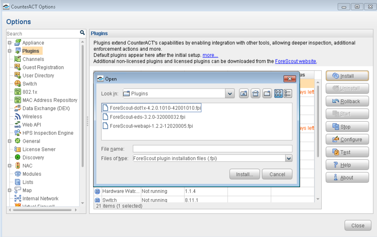
Install and Configure CounterACT Plugins
CounterACT is delivered with several bundled plugins:
ForeScout-dot1x-4.2.0.1010-42001010.fpi
ForeScout-eds-3.2.0-32000032.fpi
ForeScout-webapi-1.2.2-12020005.fpi
These plugins link CounterACT to the network infrastructure (switches, domain servers, and user directories), and provide core endpoint detection and management functionality, including a comprehensive set of host properties and actions.
- Log in to the CounterACT console and select Tools > Options > Plugins to install the packages.Figure 16: CounterACT Plugins Screen
Configure User Directory Plugin
The User Directory Plugin resolves endpoint user details and performs endpoint authentication through authentication and directory servers.
To configure the User Directory servers:
- From the Edit Server page, on the General pane, define basic server parameters and functionality:
Enter the hostname of the server in the Name field.
From the Type list, select the server type. The server type can be any one of the following:
Figure 17: Server Type Options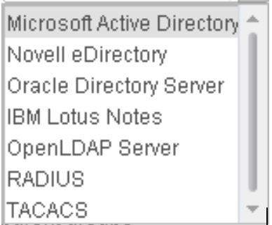
Enable these configuration parameters for the server: Use as directory, Use for authentication, and Use for Console Login.
Enter a comment about the server configuration in the Comment field.
Click the Settings tab.
- From the Test pane, define parameters
for testing the connection between the server and the User Directory
Plugin.
In the Directory section, enter the user name to query in the User field.
In the Authentication section, enter Administrator in the User field and enter and verify the administrator’s password in the Password fields.
Click OK, then click Apply to save and apply the configuration settings.
Figure 18: User Directory Plugin Parameters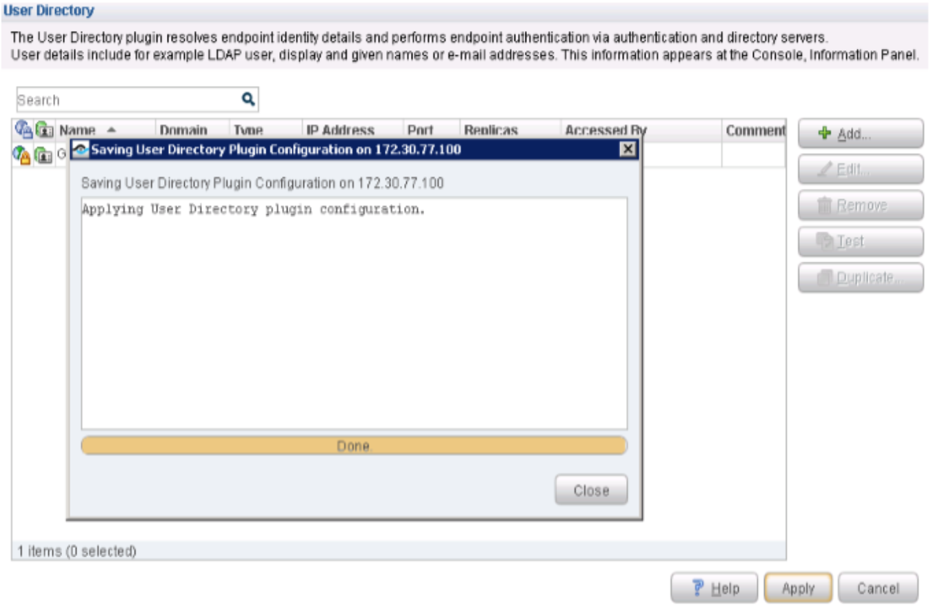
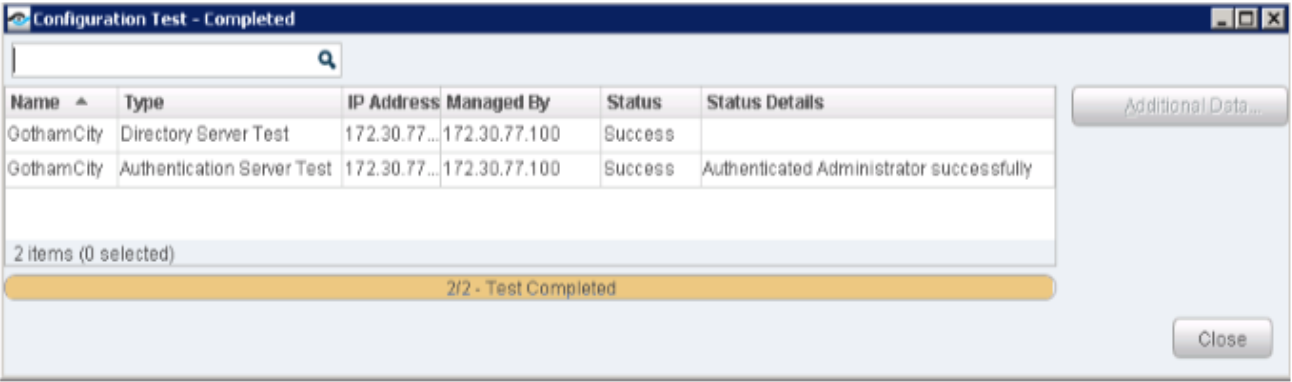
- Click Test to test your configuration.Figure 19: Configuration Test Screen
Configure Switch Plugin
The Switch Plugin queries each switch for:
Switch port attributes and information about connected endpoints.
ARP table to discover new endpoints connected to the switch.
The information can be obtained via CLI and/or SNMP.
To configure the Switch Plugin for the EX4300 switch:
- From the 802.1X pane, configure RADIUS-based
authentication and authorization for detected endpoints when attempting
to connect to a Juniper Networks’ network through an EX4300
Series switch.
In the RADIUS Secret as configured in switches fields, enter the necessary RADIUS secret to allow communication between the CounterACT RADIUS server and the managed switch.
Click OK, then click Apply to save and apply the configuration settings.
Figure 20: 802.1X RADIUS-based Authentication Secret Confirmation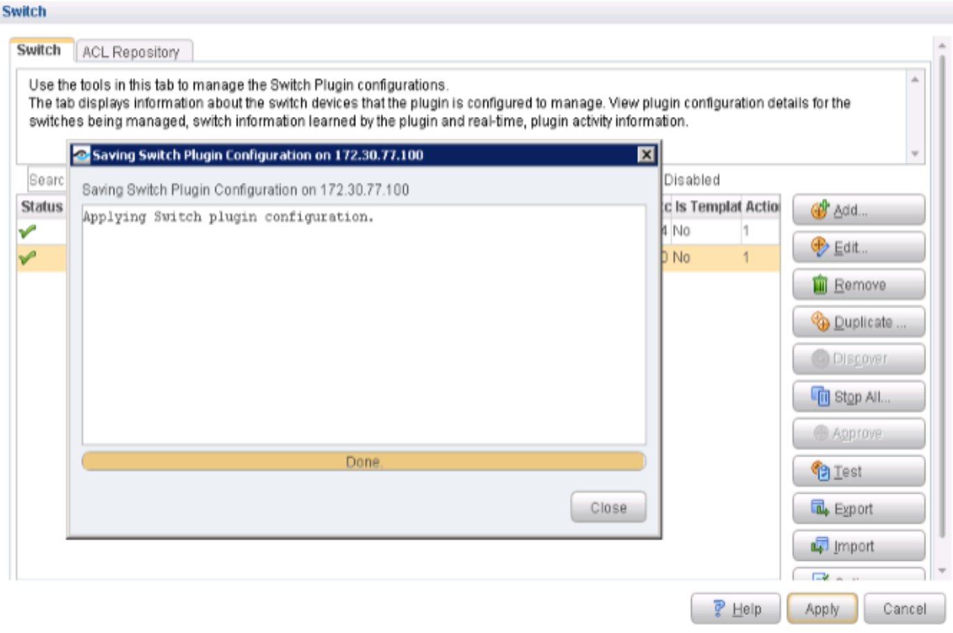
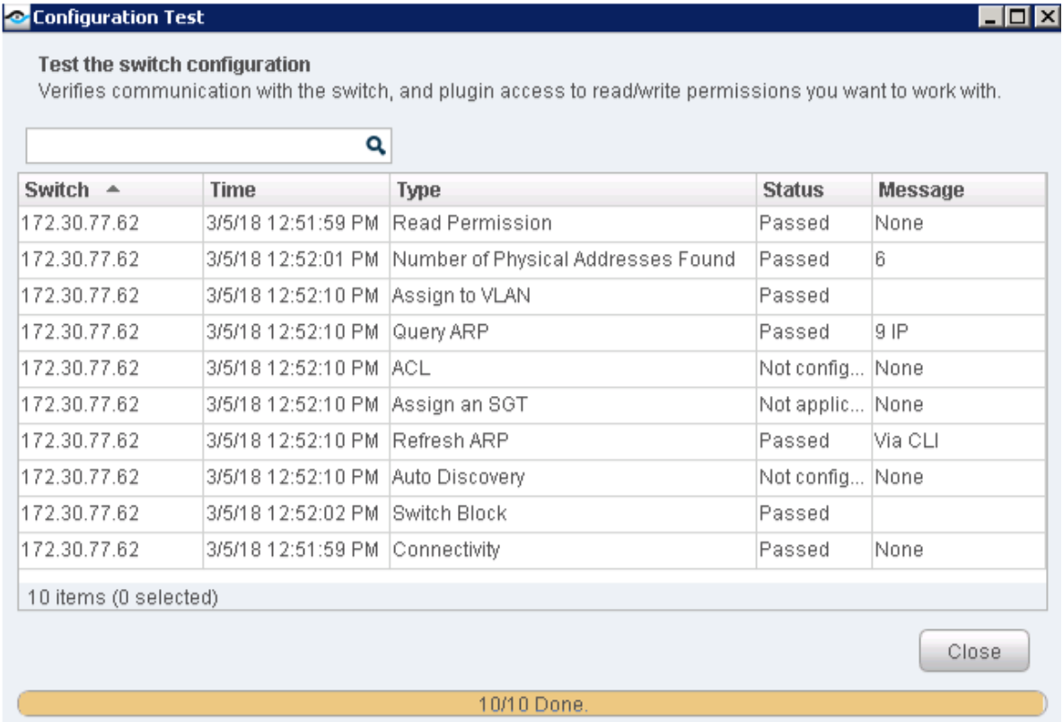
- Click Test to test your configuration.Figure 21: Switch Configuration Test Screen
 Note:
Note:To configure the QFX switch, repeat the same configuration steps as for the EX4300 switch. However, you must configure ACL functionality for the QFX switch because QFX is deployed as a standard access switch (without 802.1X), and auto-threat remediation is performed by applying ACLs.
From the User Directory page, enable and/or select the following fields from the ACL pane:
Enable ACL
Add ACL firewall filter to physical ports
Add CounterACT authentication servers permit rules
Use system-defined name (forescout_acl)
Configure 802.1X Plugin
The 802.1X Plugin enables CounterACT to authenticate 802.1X switch or wireless connections to the network. The plugin is compatible with the IEEE 802.1X specification and the RADIUS authentication protocol.
To configure the 802.1X Plugin:
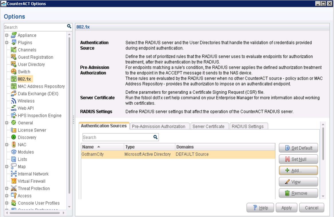
- Select Tools > Options > 802.1x.Figure 22: 802.1X Options
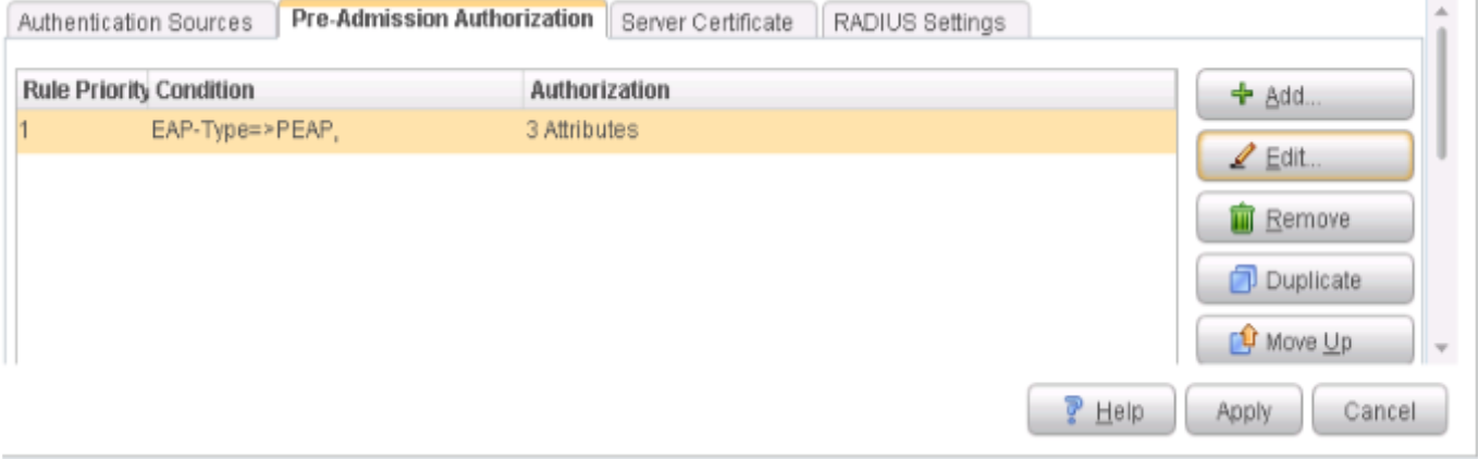
- Click the Pre-Admission Authorization tab and define a set of prioritized rules. The CounterACT RADIUS
server uses these rules to evaluate the endpoints for authorization
after they have been authenticated by the applicable RADIUS server
(an Authentication Source selection).Figure 23: Pre-Admission Authorization Tab
- Click Add to add multiple conditions
for the rule.Figure 24: Pre-Admission Authorization Conditions
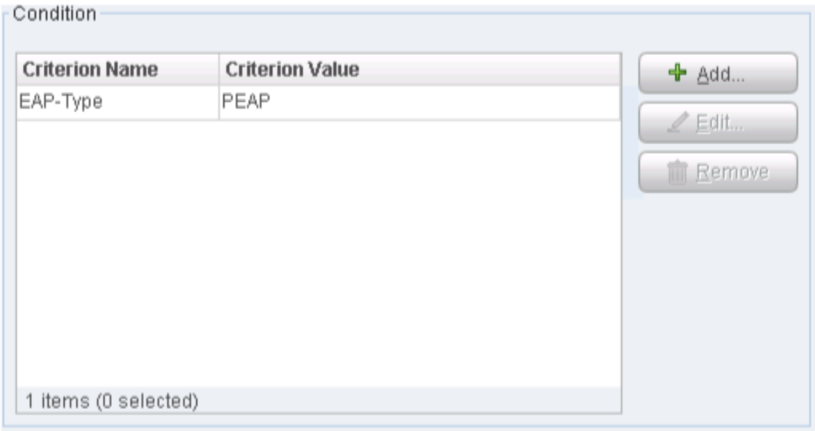
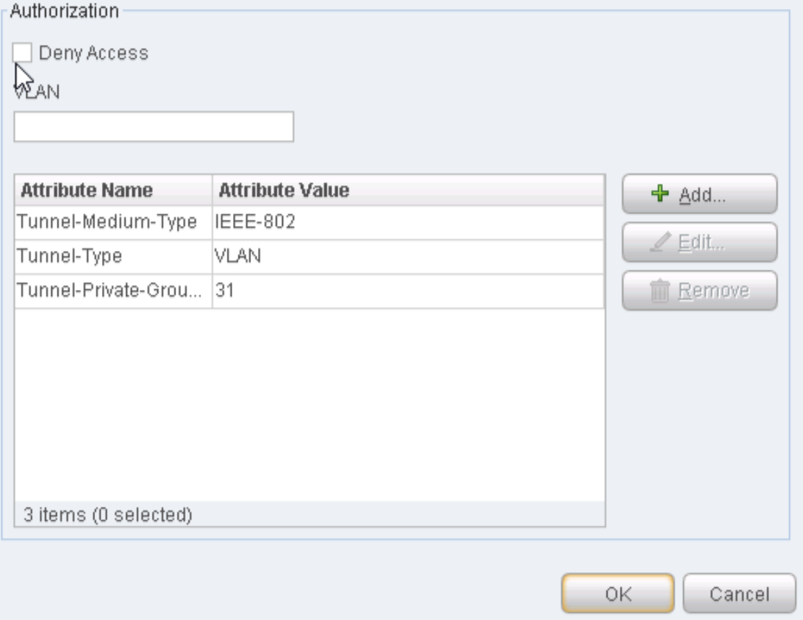
- Add your Authorization Attributes. Enter VLAN as the Tunnel-Type, and 31 as the Tunnel-Private-Group.
Click OK. Figure 25: Adding Authorization Attributes
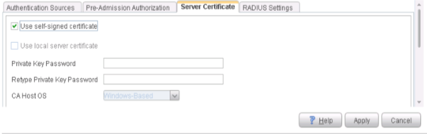
- Click the Server Certificate tab.
Enable the Use self-signed certificate option.Figure 26: Server Certificate Options
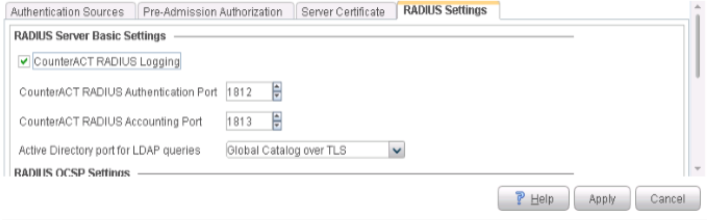
- Click the RADIUS Settings tab. Enable
the CounterACT RADIUS Logging option, and accept
all of the other default settings. Figure 27: RADIUS Settings
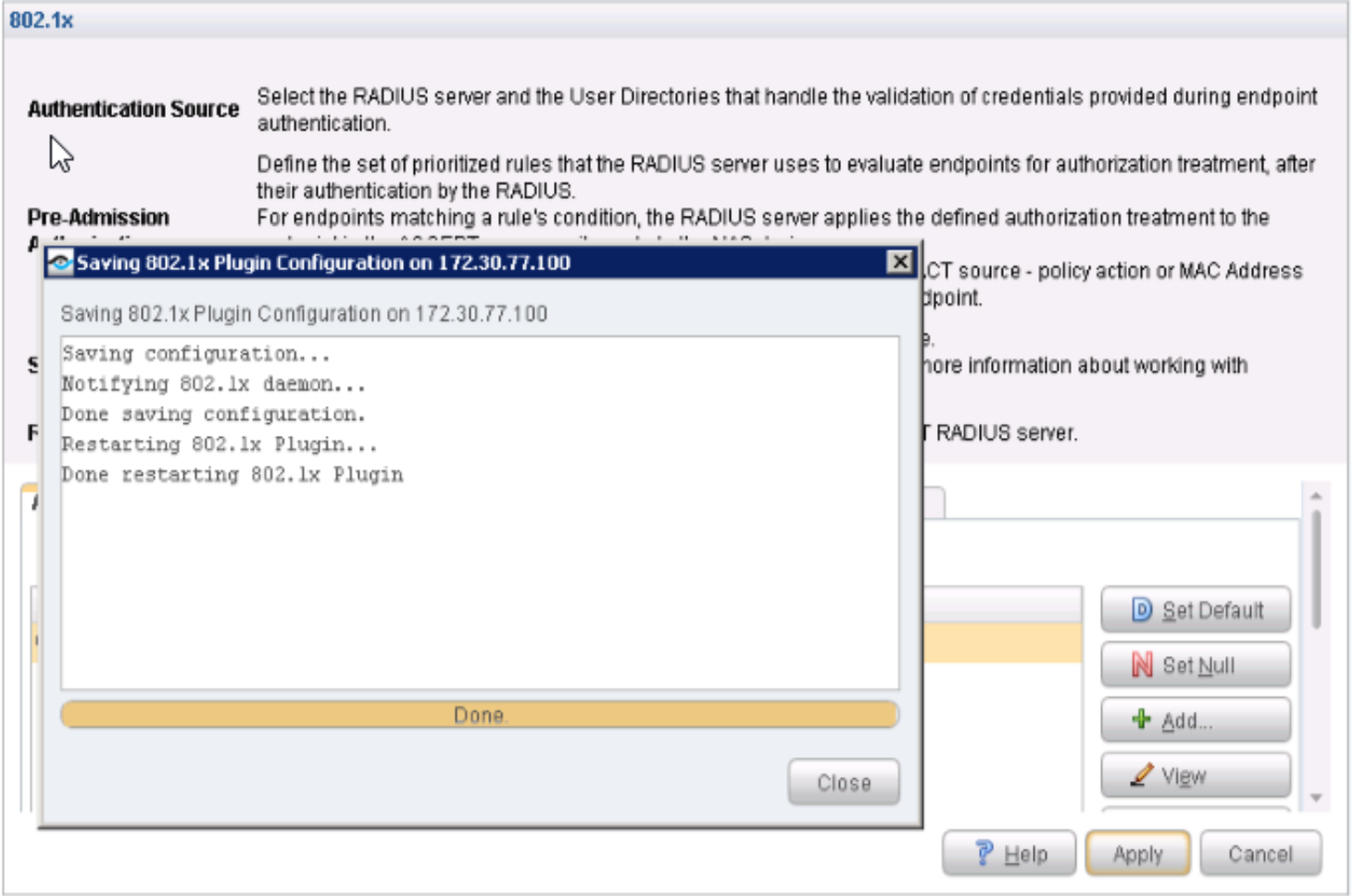
- Click Apply to save and apply the
configuration settings.Figure 28: Applying 802.1X Configuration Settings
Configure Windows 7 Supplicant
You should have already installed the Microsoft Windows Server and Active Directory. Click Install and Configure Microsoft Windows Server and Active Directory to review the instructions.
To configure the Windows 7 Supplicant:
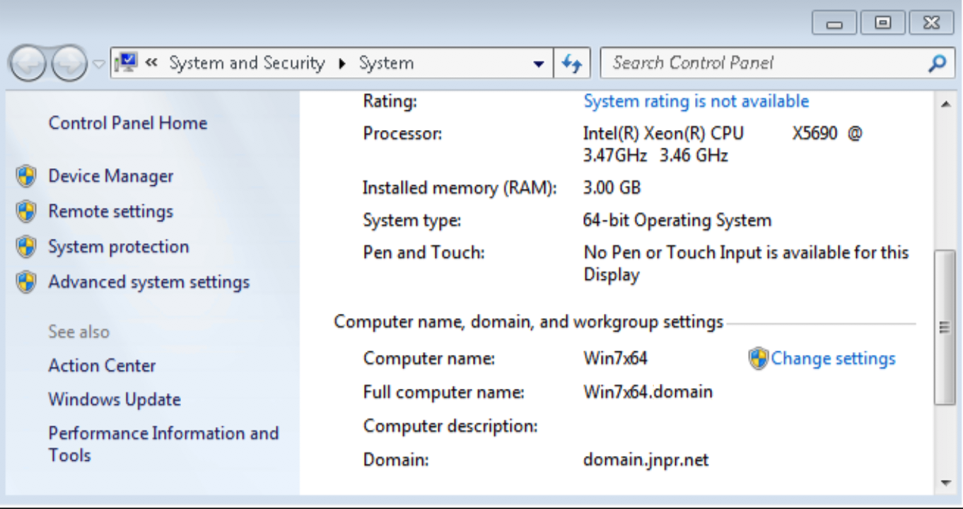
- Ensure that the Windows 7 Supplicant is configured with
the Active Directory domain that you previously created.Figure 29: Windows Supplicant Configuration Verification
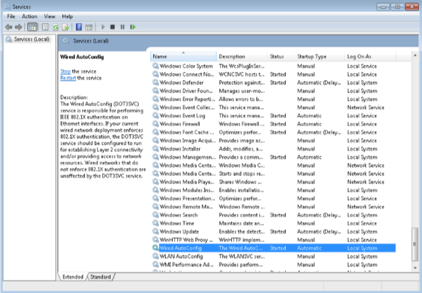
- Ensure that the Wired AutoConfig service is running.Figure 30: Wired AutoConfig Service Configuration Confirmation
- Enable 802.1X PEAP authentication for the Local Area Connection.Figure 31: 802.1X PEAP Authentication Confirmation
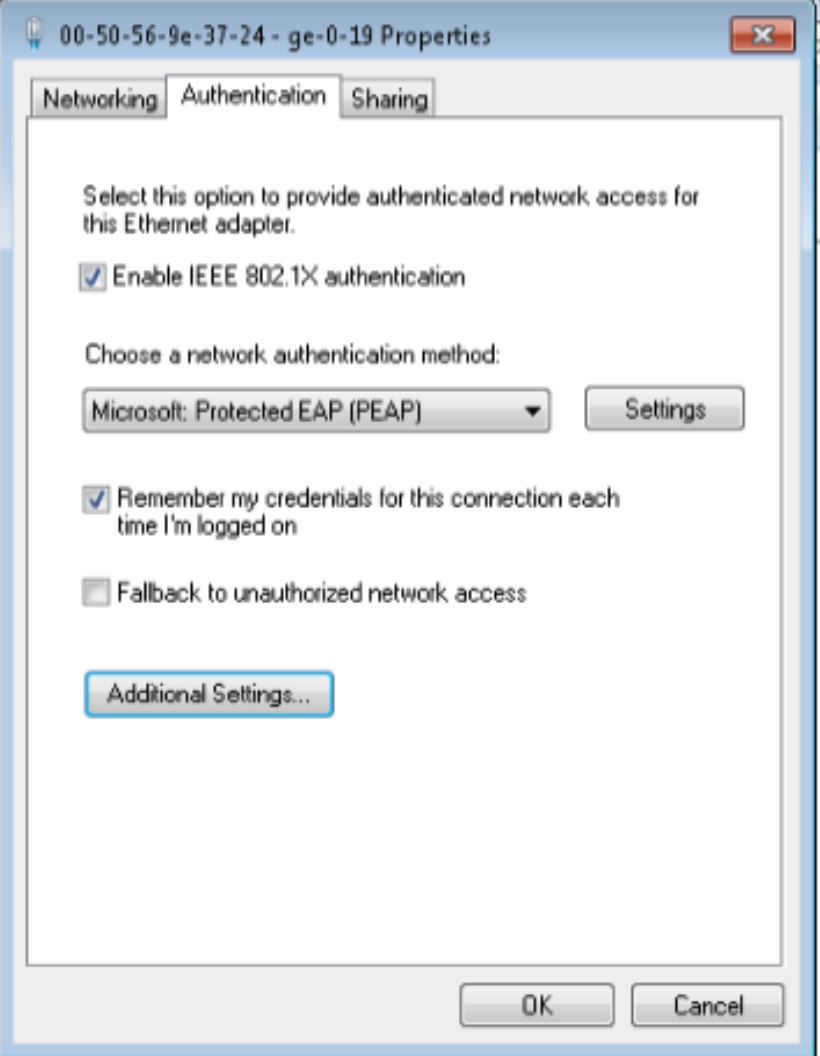
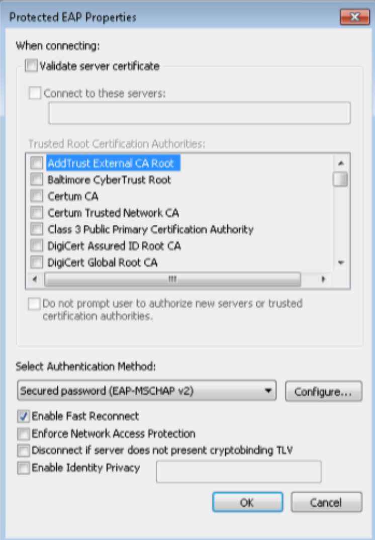
- Click Settings and ensure that the Validate server certificate option is not selected.Figure 32: Protected EAP Properties
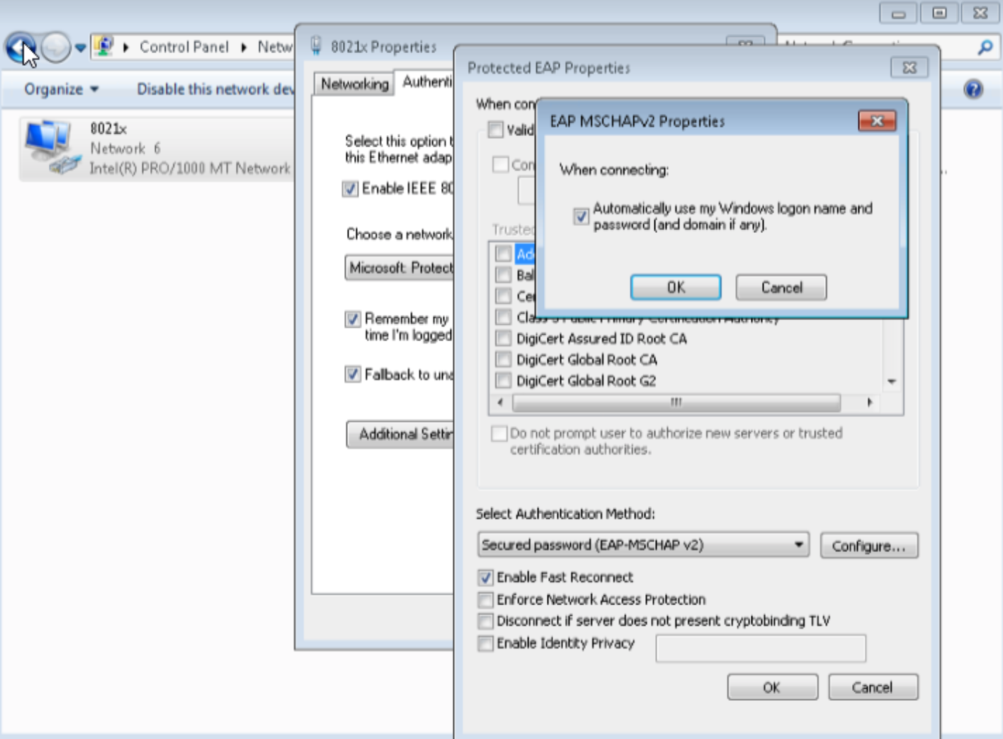
- Configure the user credential settings. Select the Automatically use my Windows login name and password option
to use the user credentials you previously configured in Active Directory. Figure 33: Windows Login and Password Confirmation
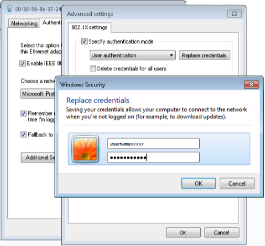
- Click Authentication > Additional Settings >
Replace credentials and enter the credentials of the user
you created in Active Directory.Figure 34: Replacing Credentials
- To confirm that the 802.1X authentication works on Windows
7 Supplicant and verify that the user is placed correctly in the User
VLAN (vlan31), enter the
show dot1x interfaceandshow vlans vlan31commands.Figure 35: show dot1X interface and show vlans Output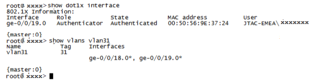
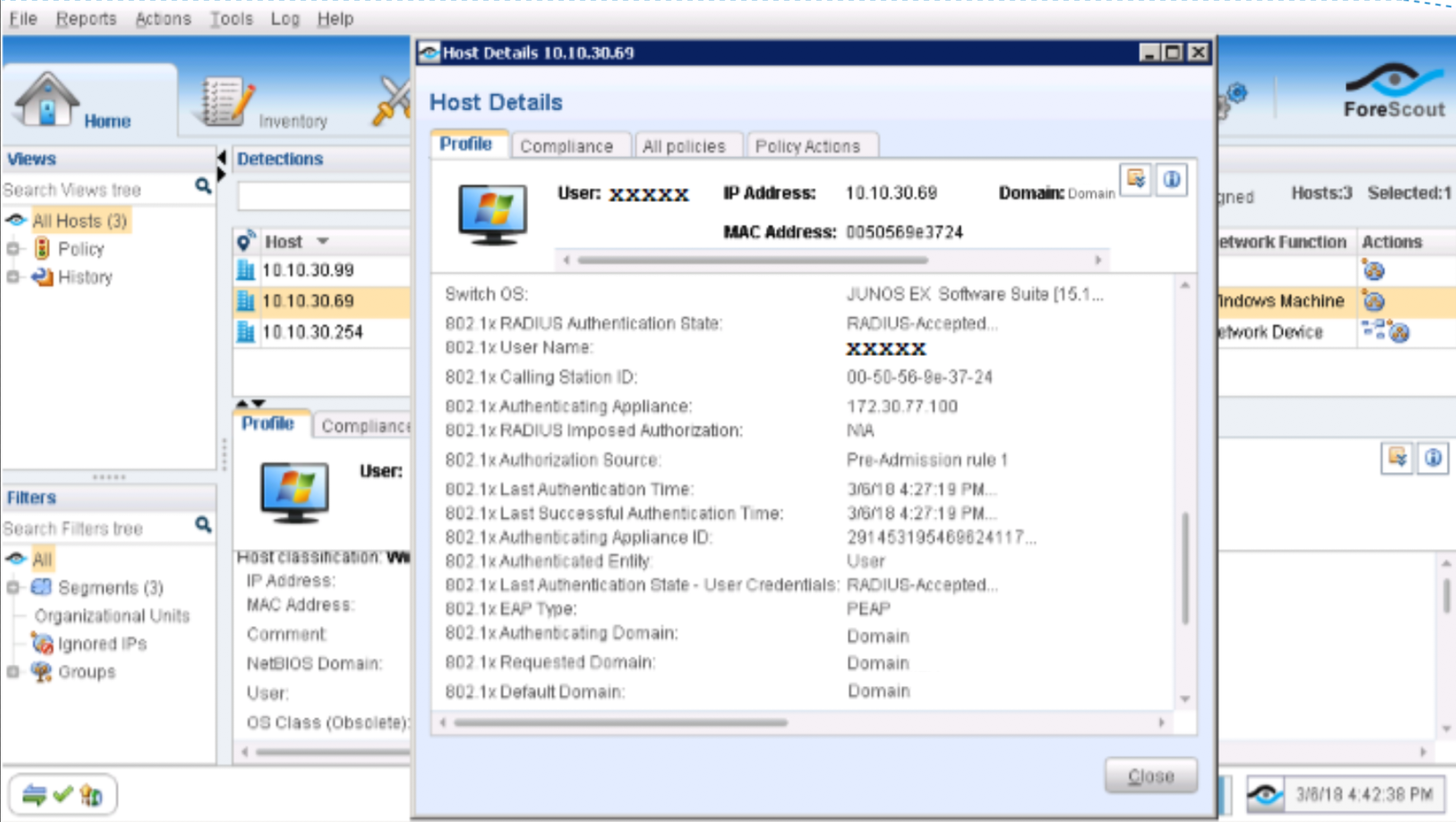
- To review the session information (username, IP address,
and MAC-ID) on the CounterACT Console, right-click on your host, and
select Information > Details.Figure 36: Session Information Verification
Test and Troubleshoot 802.1X Authentication
To test the 802.1X authentication against ForeScout CounterACT:
- Log in using the credentials of the domain account (user)
you created in the User Directory. Figure 37: Troubleshoot Rejected Authentications
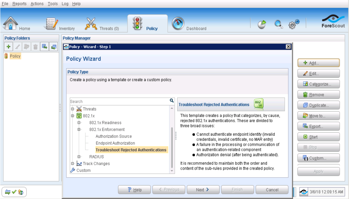
To troubleshoot 802.1X authentication issues:
From the ForeScout CounterACT Console, click the Policy tab and create a policy using the Troubleshoot Rejected Authentications template (listed under 802.1X Enforcement).
Start your policy to troubleshoot the issue.
To view logs from the ForeScout CounterACT Console:
Select Log > Policy Log. From the Policy Log page, enter your Windows 7 supplicant’s MAC or IP address.
Figure 38: Policy Log Settings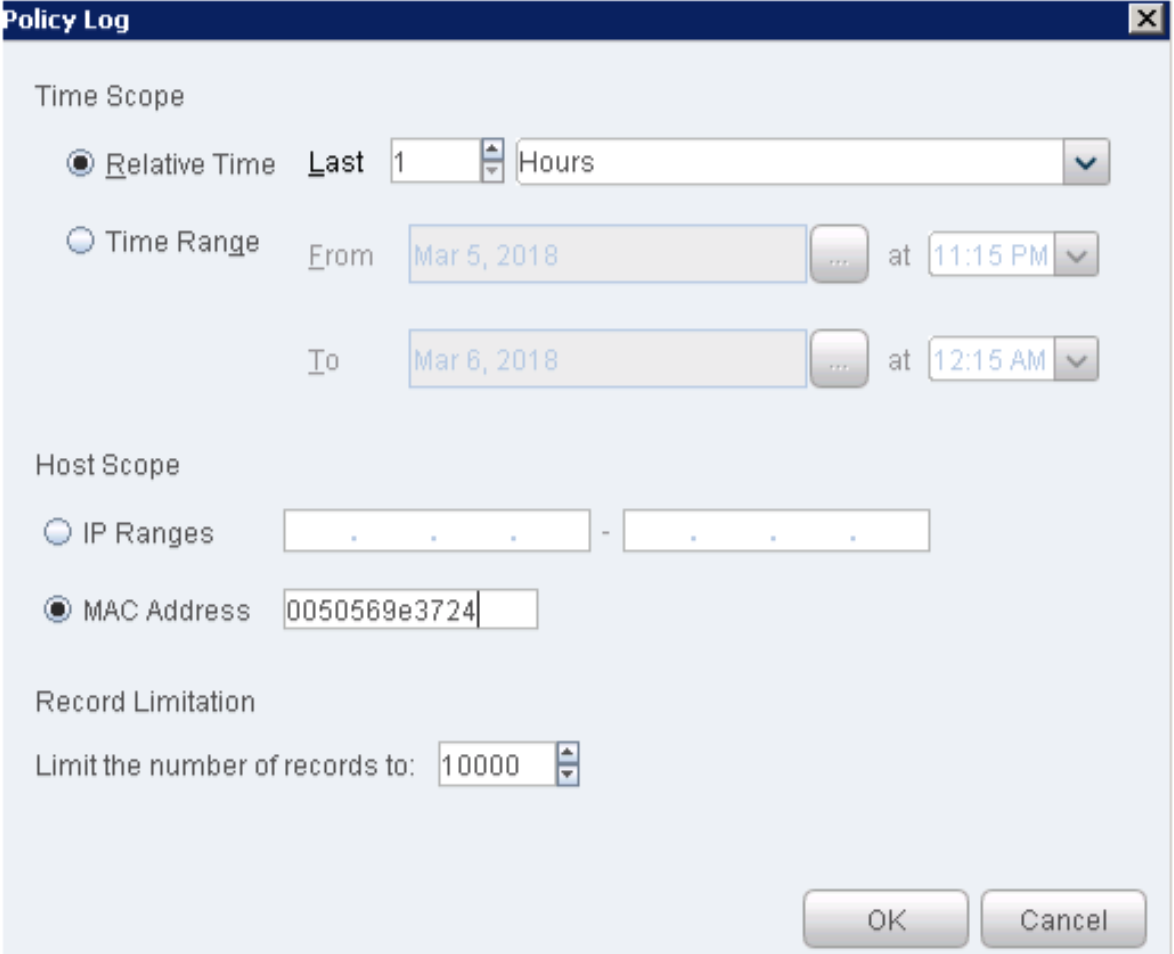
Click OK. The policy log files appear.
Figure 39: Policy Log Files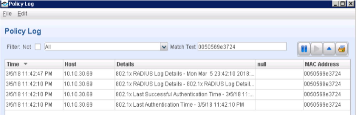
If 802.1X authentication works and your Windows 7 supplicant obtains an IP address from the DHCP server running on SRX, you can then generate some traffic to verify that your Windows 7 supplicant (for example, 10.10.30.69) appears on the Host list under the Home tab.
Figure 40: Policy Log 802.1X Authentication Confirmation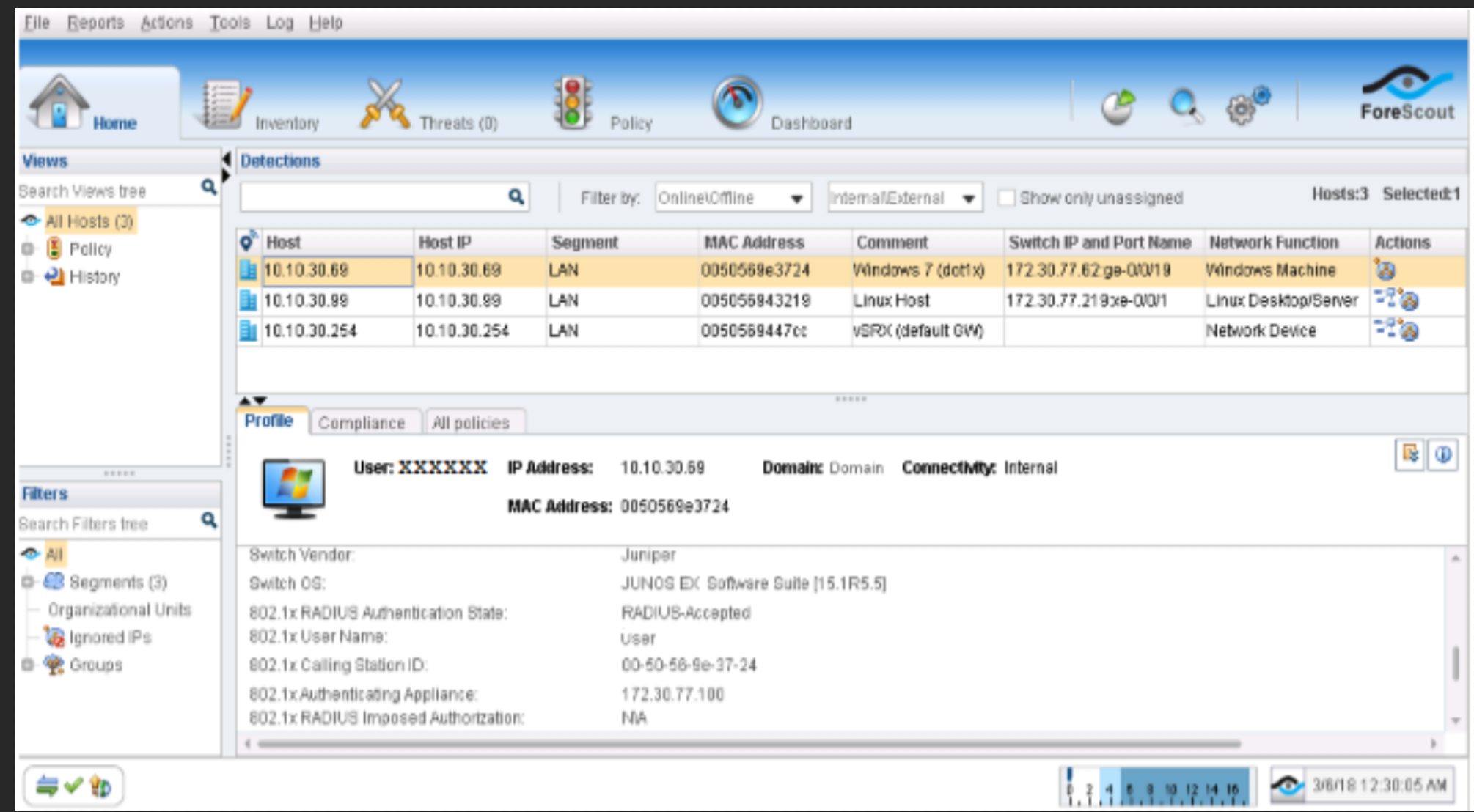 Note:
Note:Additionally, if you already configured the other host (Windows or Linux system) that is connected to the QFX switch and obtained an IP address from the DHCP server running on SRX, you can then generate some traffic for it, and the host address (for example, 10.10.30.99) will also appear on the Host list.
Configure Data Exchange Plugin
The Data Exchange (DEX) Plugin enables CounterACT to use web services to communicate with external entities. CounterACT queries external services and receives updates through the CounterACT web service hosted by the plugin. In this case DEX in conjunction with the ForeScout Connector will monitor PE for any communication.
To configure the Data Exchange (DEX) Plugin:
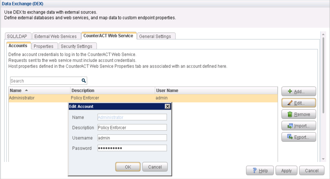
- From the Data Exchange (DEX) page, select CounterACT
Web Service > Accounts tab.Figure 41: Data Exchange Accounts
- Click the Properties tab. From the
Properties page, click Add to add the following
properties:
block
quarantine
Test
Note:You must include the Test property; otherwise, you cannot add CounterACT as a third-party connector to Policy Enforcer successfully.
Figure 42: Data Exchange Properties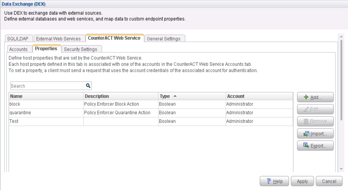
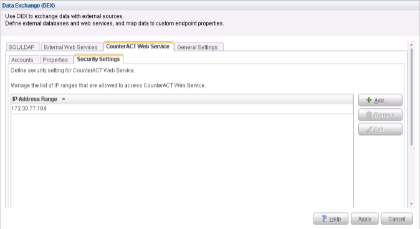
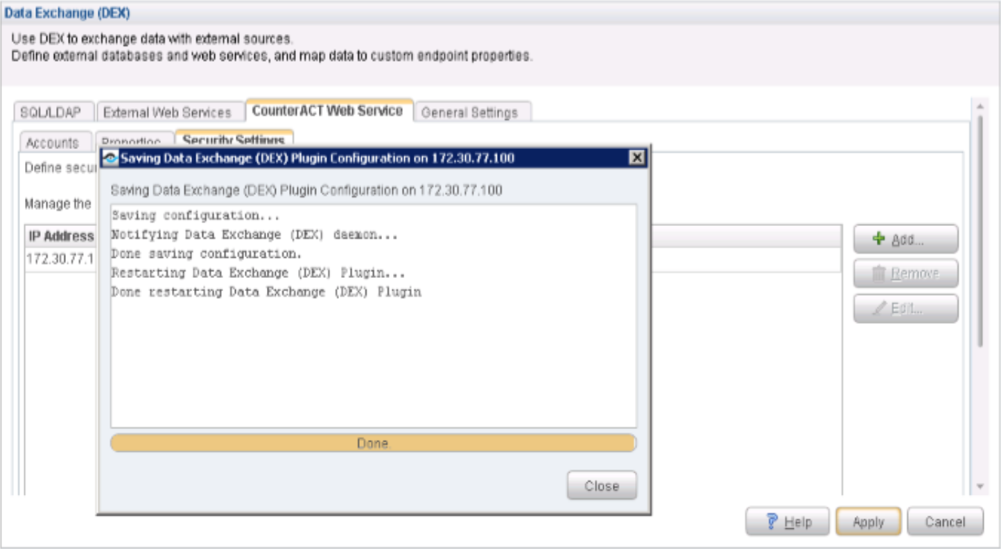
- Click the Security Settings tab.
A white list of IP addresses is used to permit access to the CounterACT
web service. From the Security Settings page, click Add and add the IP address range for the Policy Enforcer. Click OK. The IP address appears in the IP Address Range list. Figure 43: Data Exchange Security Settings
- From the Data Exchange (DEX) page, click Apply to save and apply the configuration settings.Figure 44: Data Exchange Applying Configuration Settings
Configure Web API Plugin
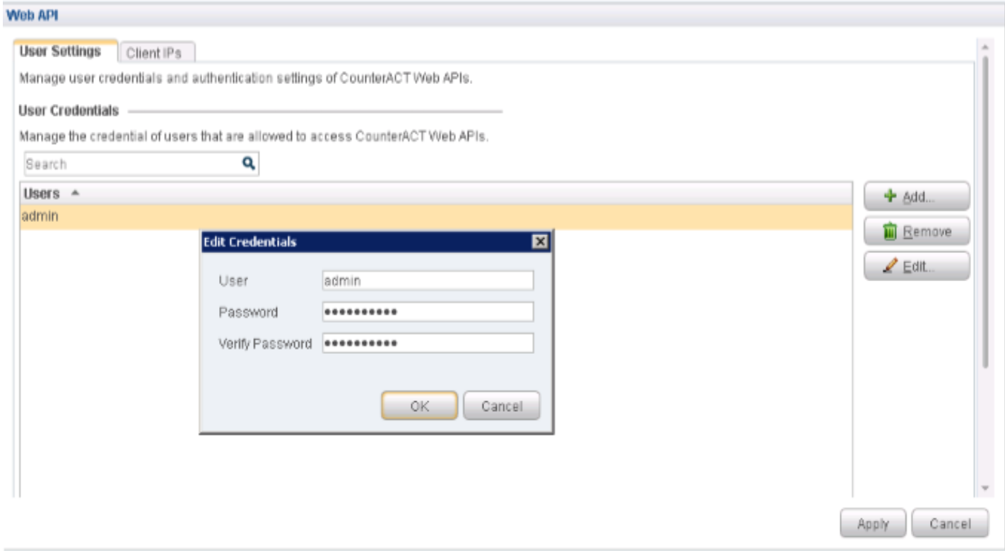
The Web API Plugin enables external entities to communicate with CounterACT using simple, yet powerful web service requests based on HTTP interaction. Configure the Web API Plugin to create an account for Policy Enforcer integration.
To configure the Web API Plugin:
- From the Web API page, in the User Credentials section,
click Add.Figure 45: Web API User Credentials
- Click the Client IPs tab and click Add. Add the Policy Enforcer IP address into the access
list.
Click OK.
Figure 46: Web API Client IP Tab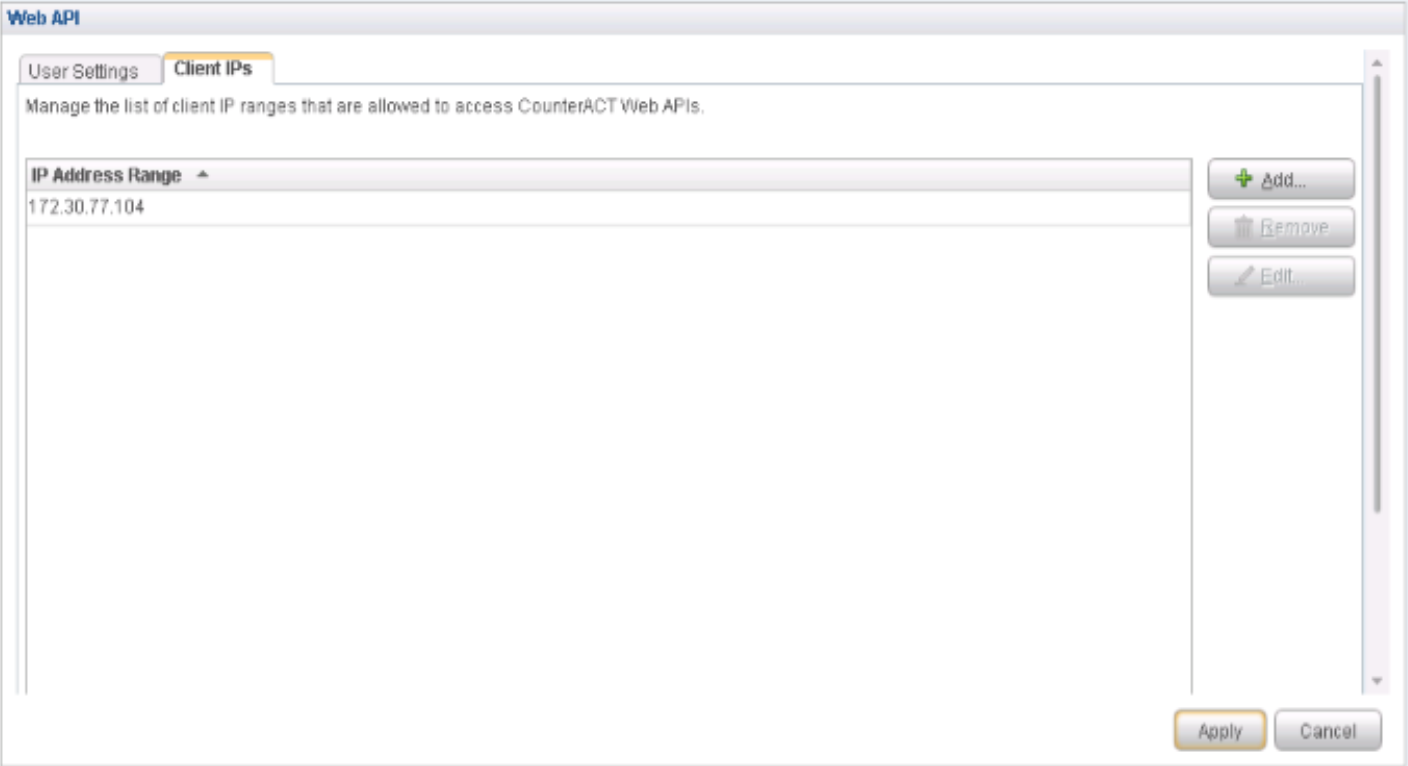
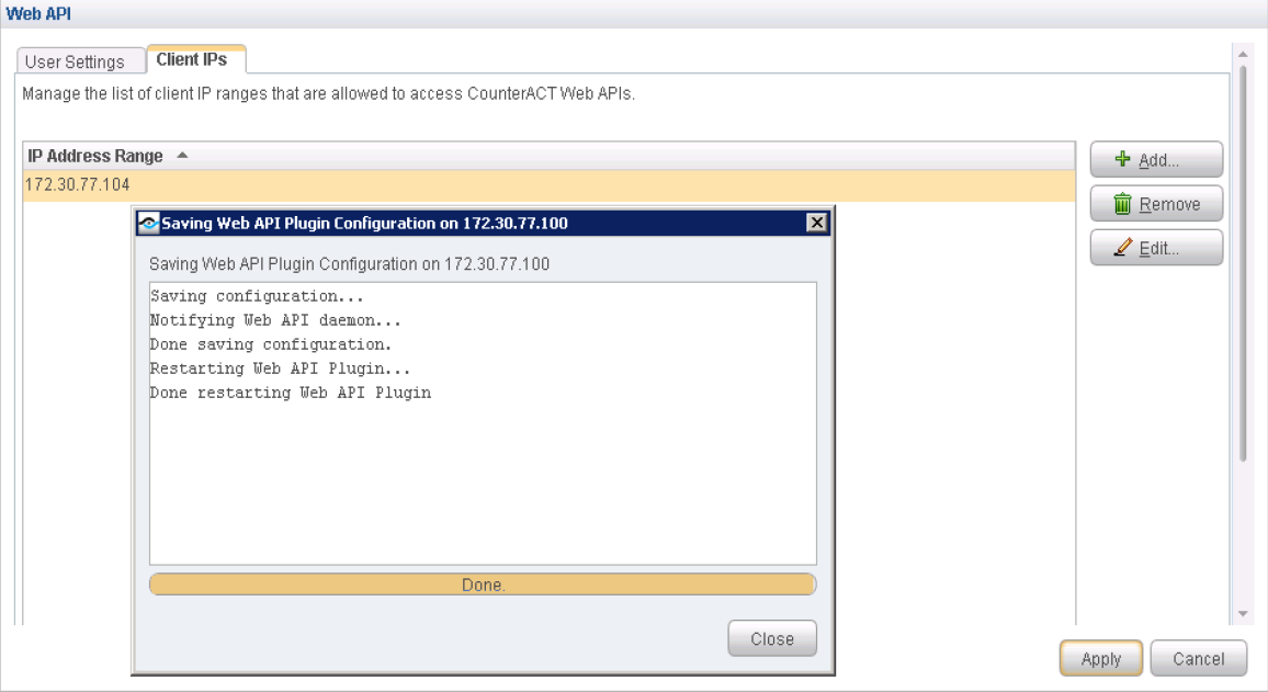
- From the Web API page, click Apply to save and apply the configuration settings.Figure 47: Web API Applying Configuration Settings
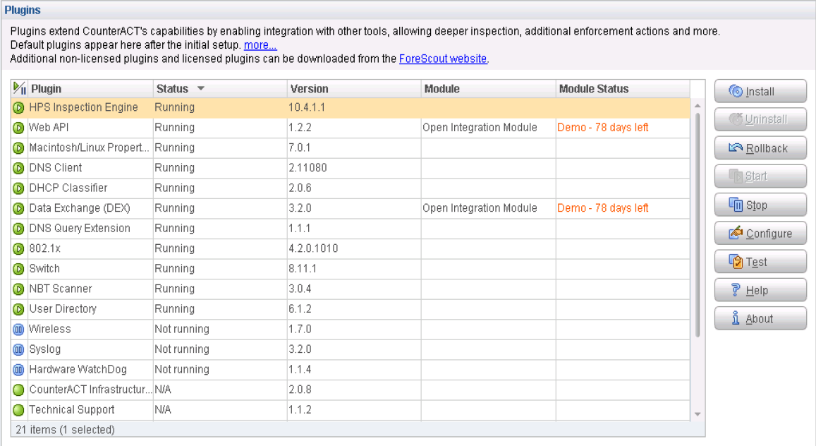
Verify Plugins
To verify that all of the required plugins are running, select Tools > Options > Plugins. The Plugins page appears showing the status of each plugin.
Configure Automated Threat Remediation Policies
Using Policy Manager, create these automated threat remediation policies:
NETCONF policies–used to connect hosts to the QFX switch.
802.1X policies–used to connect hosts to the EX4300 switch and used for 802.1X authentication.
To create an automated threat remediation NETCONF policy or 802.1X policy:
- From the Policy Manager page, click Add.Figure 49: Policy Manager Page
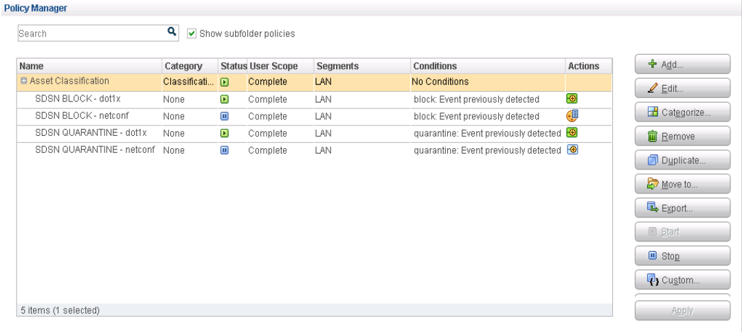
- Click Custom and click Next.
a. Based on your requirements, create the following sets of SDSN block and quarantine policies to secure host-to-switch and switch-to-802.1X server traffic. In the Name field, enter these policy names:
SDSN BLOCK—dot1x
SDSN QUARANTINE—dot1x
SDSN BLOCK—NETCONF
SDSN QUARANTINE—NETCONF
Figure 50: Block and Quarantine Policies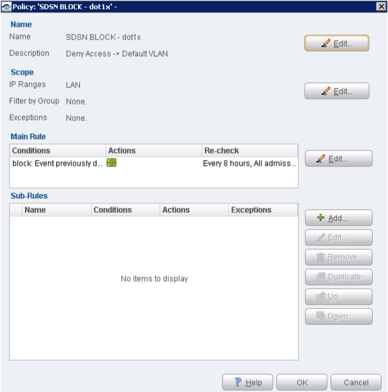
In the Description field, enter a description for each policy. Click Next.
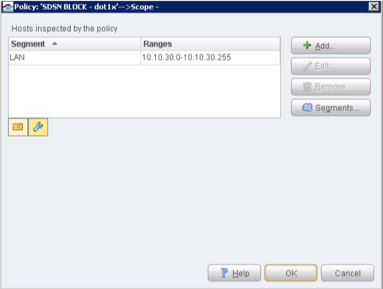
- From the Scope page, select the IP Range option. Enter the IP address range for the LAN
segment as endpoints to be inspected for this policy. Click OK. Figure 51: IP Address Range in Block and Quarantine Policies
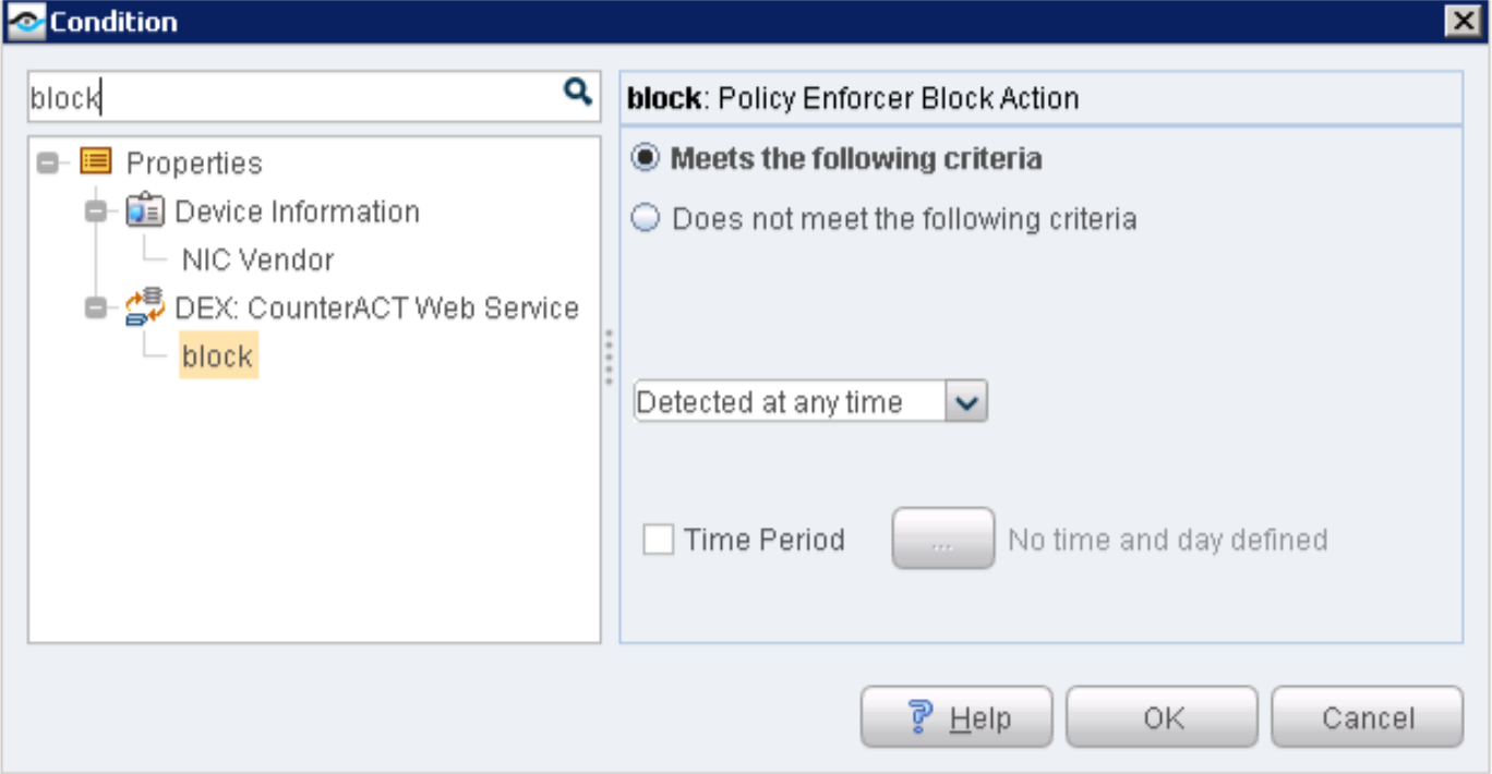
- From the Main Rule page, click Add from the Condition section of the page to add a condition.Figure 52: Adding Conditions to Block and Quarantine Policies
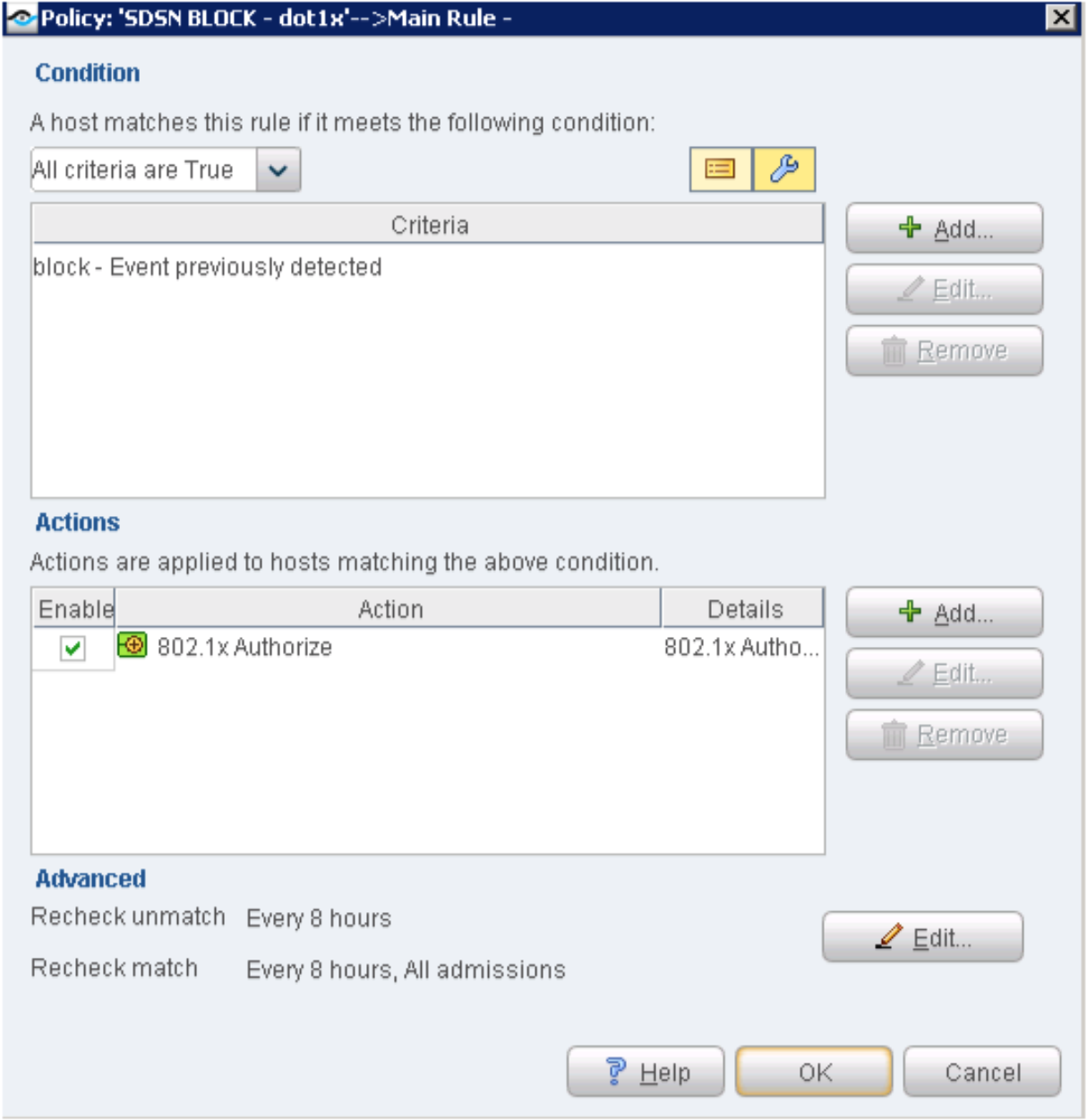
- Define the condition for block or quarantine.Figure 53: Defining Conditions for Block and Quarantine Policies
- From the Main Rule page, click Add from the Actions section of the page. From the Action page, define these actions:
SDSN BLOCK - dot1x─select 802.1x Authorize in the left pane and enable the Deny Access option as an action.
Figure 54: 802.1X Blocking Access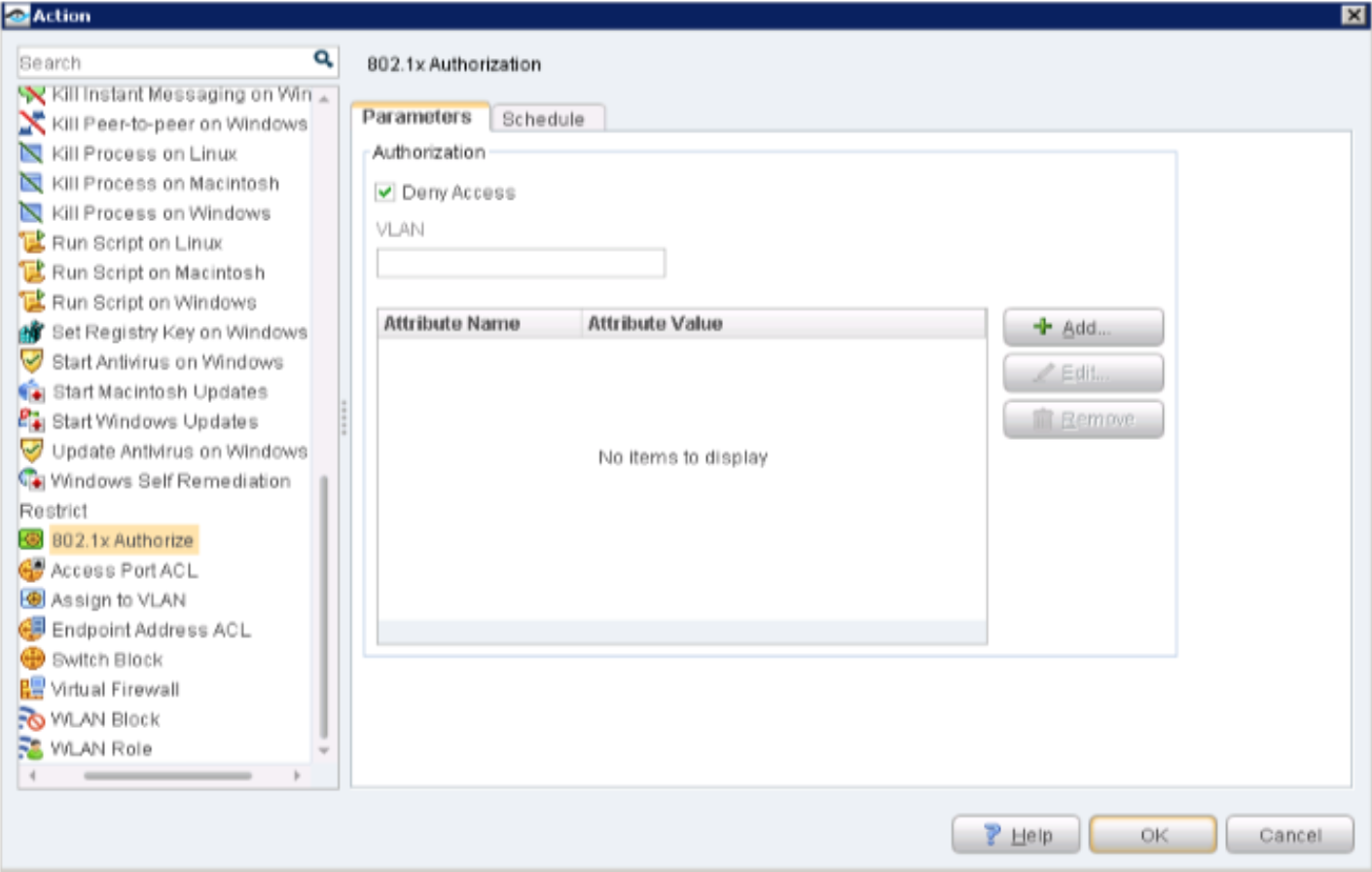
SDSN QUARANTINE - dot1x─select 802.1x Authorize in the left pane and enter vlan32 in the VLAN field as an action.
Figure 55: 802.1X Quarantine Traffic to a VLAN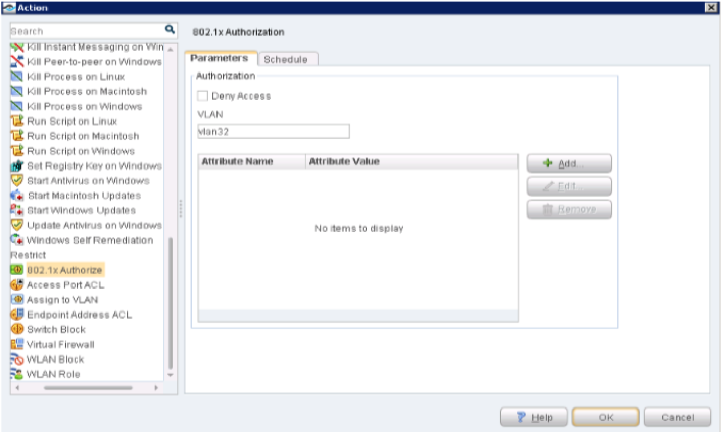
SDSN BLOCK - NETCONF─select Endpoint Address ACL in the left pane and enter an ACL as an action in the Parameters tab.
Figure 56: Endpoint Access ACL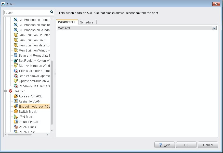
SDSN QUARANTINE - NETCONF─select Assign to VLAN in the left pane and enter vlan32 in the VLAN name field under the Parameters tab to add as an action.
Figure 57: SDSN Quarantine Assign to VLAN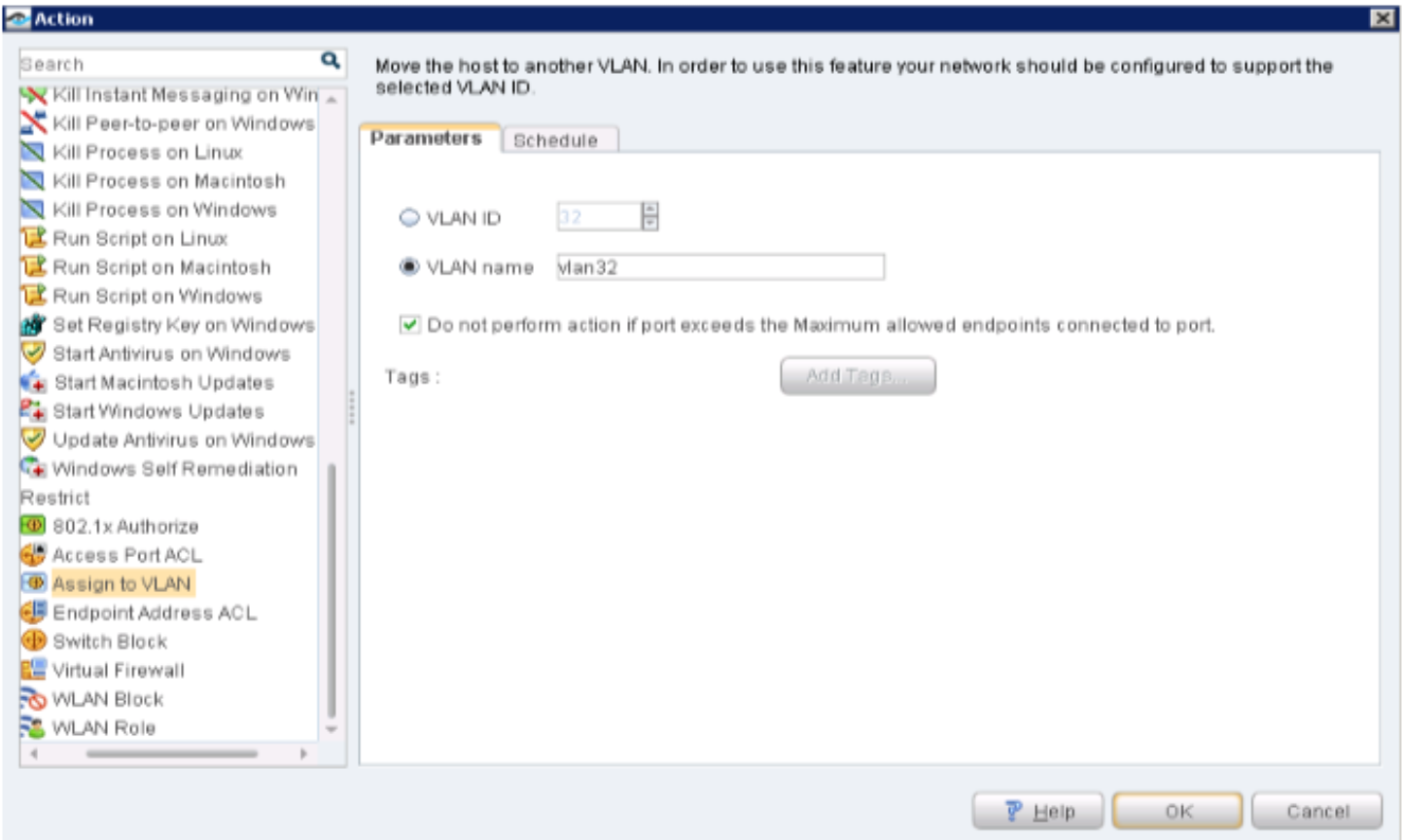
Configure the Policy Enforcer Connector for Third-Party Switches
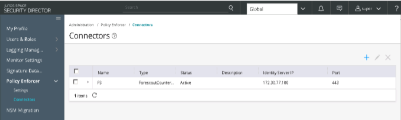
- Log in to Security Director and navigate to Administration > Policy Enforcer > Connectors and create
a new connector. A blue loading/wait circle indicates that creation
of the connector is in progress.Figure 58: Connectors
Configure ATP Cloud with Threat Prevention Policies
To configure ATP Cloud and set up threat prevention policies:
Configure a secure fabric. A secure fabric is a collection of sites which contain network devices (switches, routers, firewalls, and other security devices) used in policy enforcement groups.
Define a site and add endpoints to it (switches and firewalls).
Configure policy enforcement groups. A policy enforcement group is a grouping of endpoints to which threat prevention policies are applied.
Create a threat prevention policy.
Apply threat prevention policies to policy enforcement groups
If you are using Policy Enforcer for threat prevention with ATP Cloud, Guided Setup is the most efficient way to complete the initial configuration.
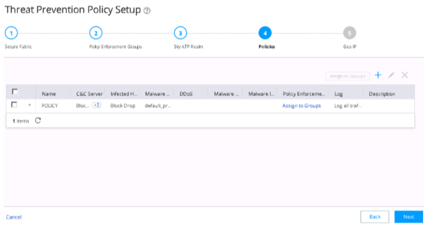
To perform the configuration using Guided Setup:
- In Security Director, navigate to Configure
> Guided Setup > Threat Prevention.Figure 59: Threat Prevention Policy Setup
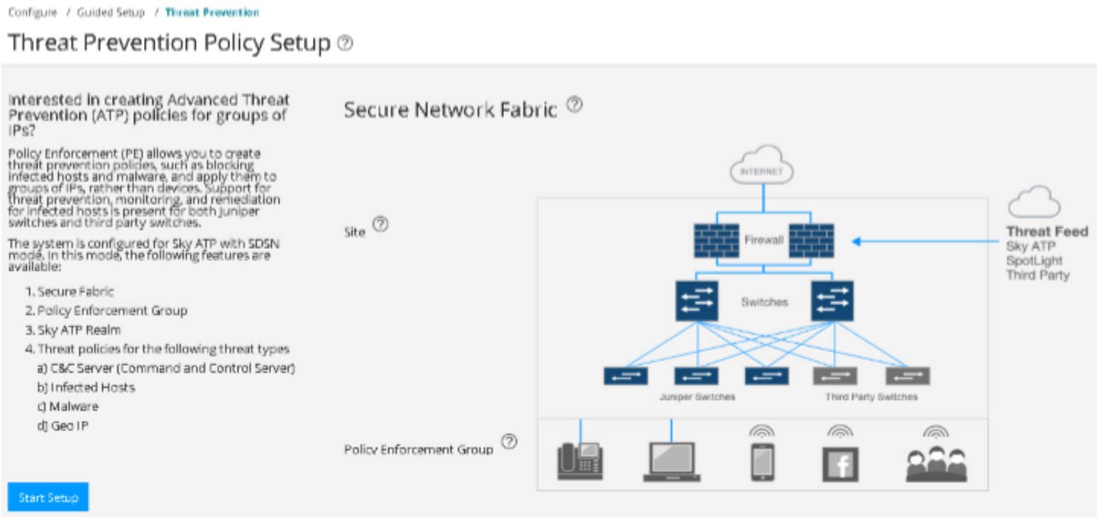
- Click Start Setup and follow the
wizard. Figure 60: Sky ATP with SDSN Setup

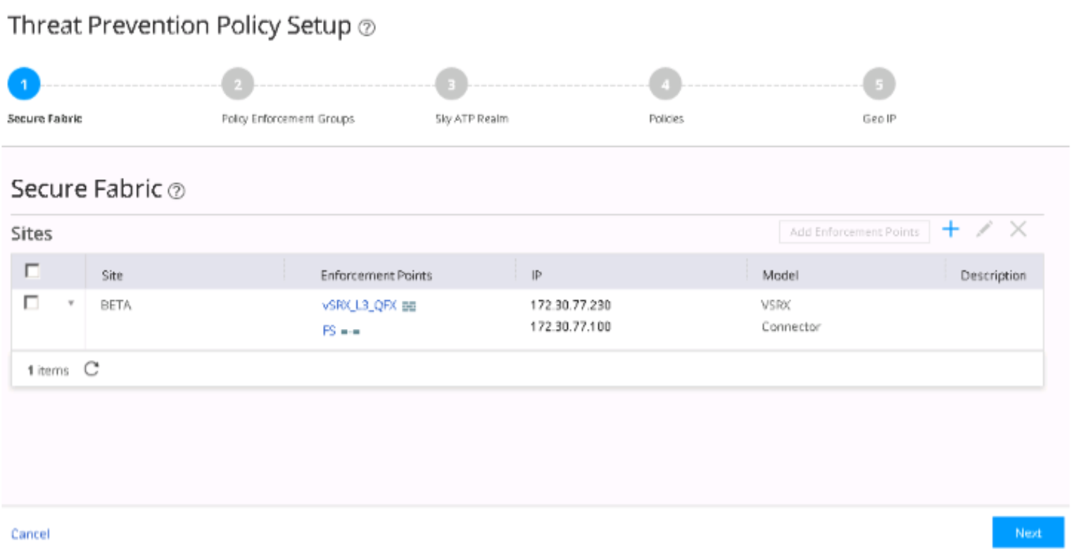
- Create a secure fabric site that includes enforcement
points for only the SRX Series device and the ForeScout CounterACT
connector. Click Next.Figure 61: Secure Fabric Threat Prevention Policy Setup
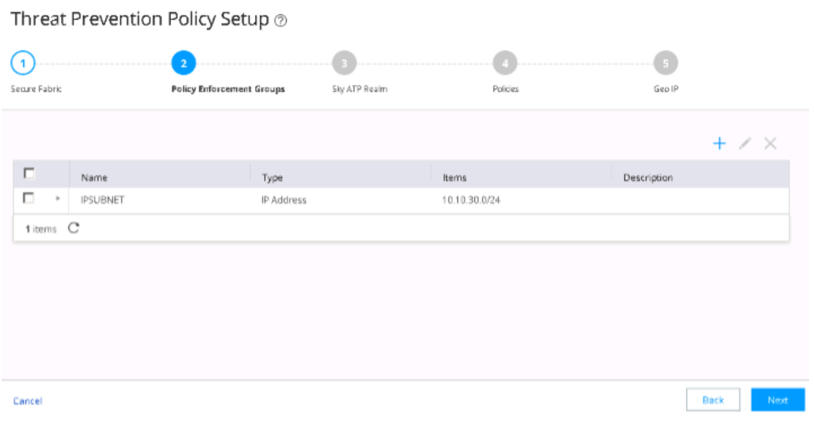
- Create a policy enforcement group and select the site.
As per your requirements, determine the type of endpoints you are
including in your policy enforcement group: IP address, subnet, or
location. Endpoints cannot belong to multiple policy enforcement groups.
Click Next.Figure 62: Policy Enforcement Groups
- Add the ATP Cloud realm by providing the relevant details
from your ATP Cloud account.
Before you configure the ATP Cloud realm, ensure that you:
Have an ATP Cloud account with an associated license.
Understand which type of ATP Cloud license you have: free, basic, or premium. The license controls which ATP Cloud features are available. Click Obtain an ATP Cloud license and Create an ATP Cloud Web Portal Account for more details.
Know which region is covered by the realm you are creating. You must a select a region when you configure a realm.
Figure 63: Sky ATP Realm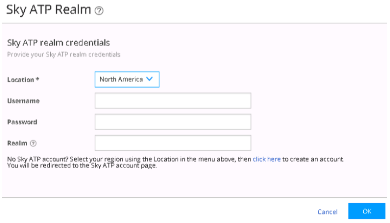
Enter Location, Username (Your username for ATP Cloud is your e-mail address), Password, and a name for the Realm. Click OK.
- Verify that the ATP Cloud realm has been added.Figure 64: ATP Cloud Realm Creation Verification
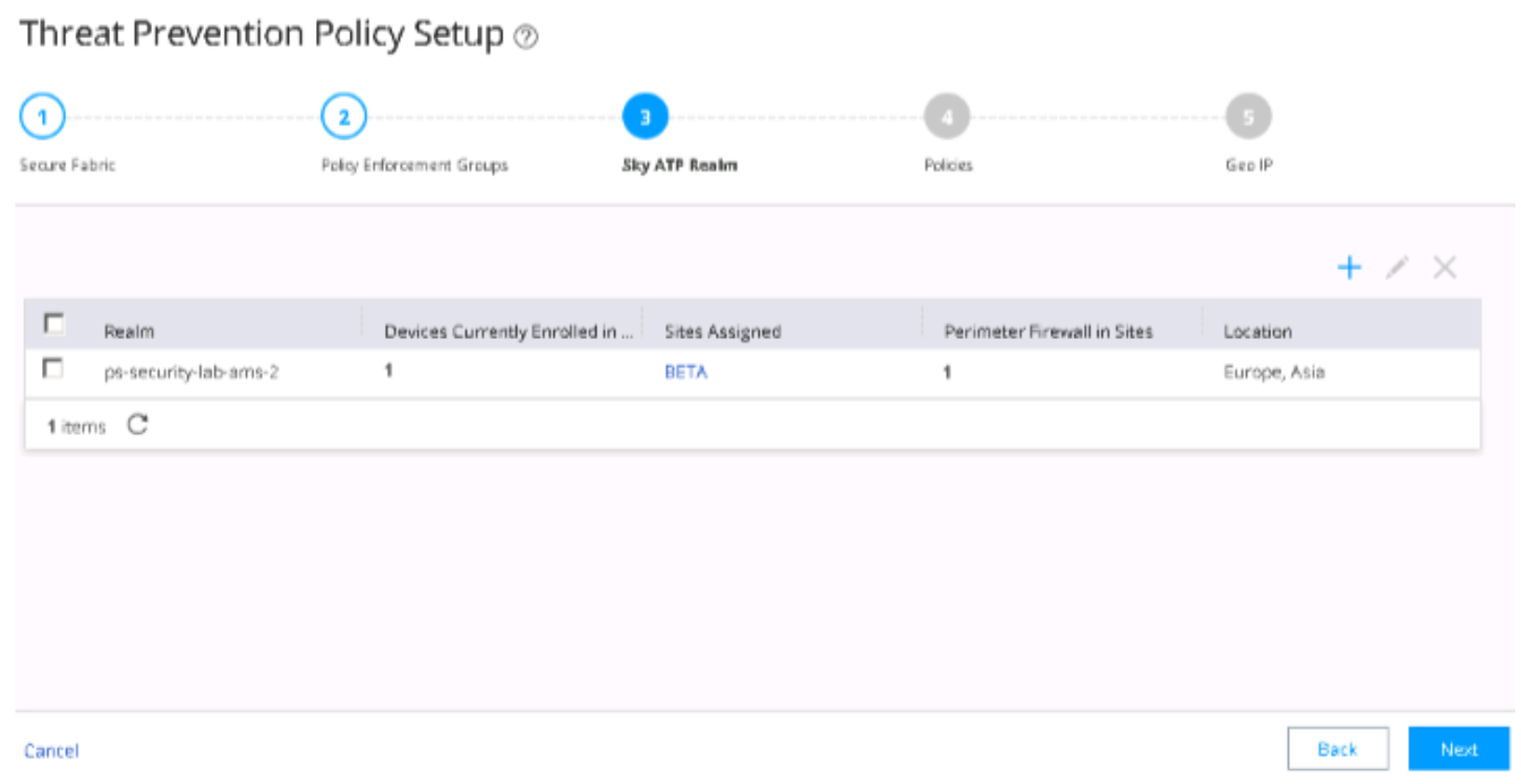
The value 1 should appear in the Perimeter Firewall in Sites column, indicating that ATP Cloud has detected the SRX Series device.
Note:If the realm addition is not successful, it indicates that there is a network issue and Security Director or Policy Enforcer cannot connect to the Internet. Ensure all devices/components can connect to the Internet and each other.
- Create a threat prevention policy, as per your requirements.
Threat prevention policies provide protection and monitoring for selected
threat profiles, including command & control (C&C) servers,
infected hosts, and malware.
Determine the type of profile to use for this policy: C&C server, infected hosts, or malware. You can select one or more threat profiles in a policy.
Determine which action to take if a threat is found.
Know which policy enforcement group to add to this policy.
Figure 65: Create Threat Prevention Policy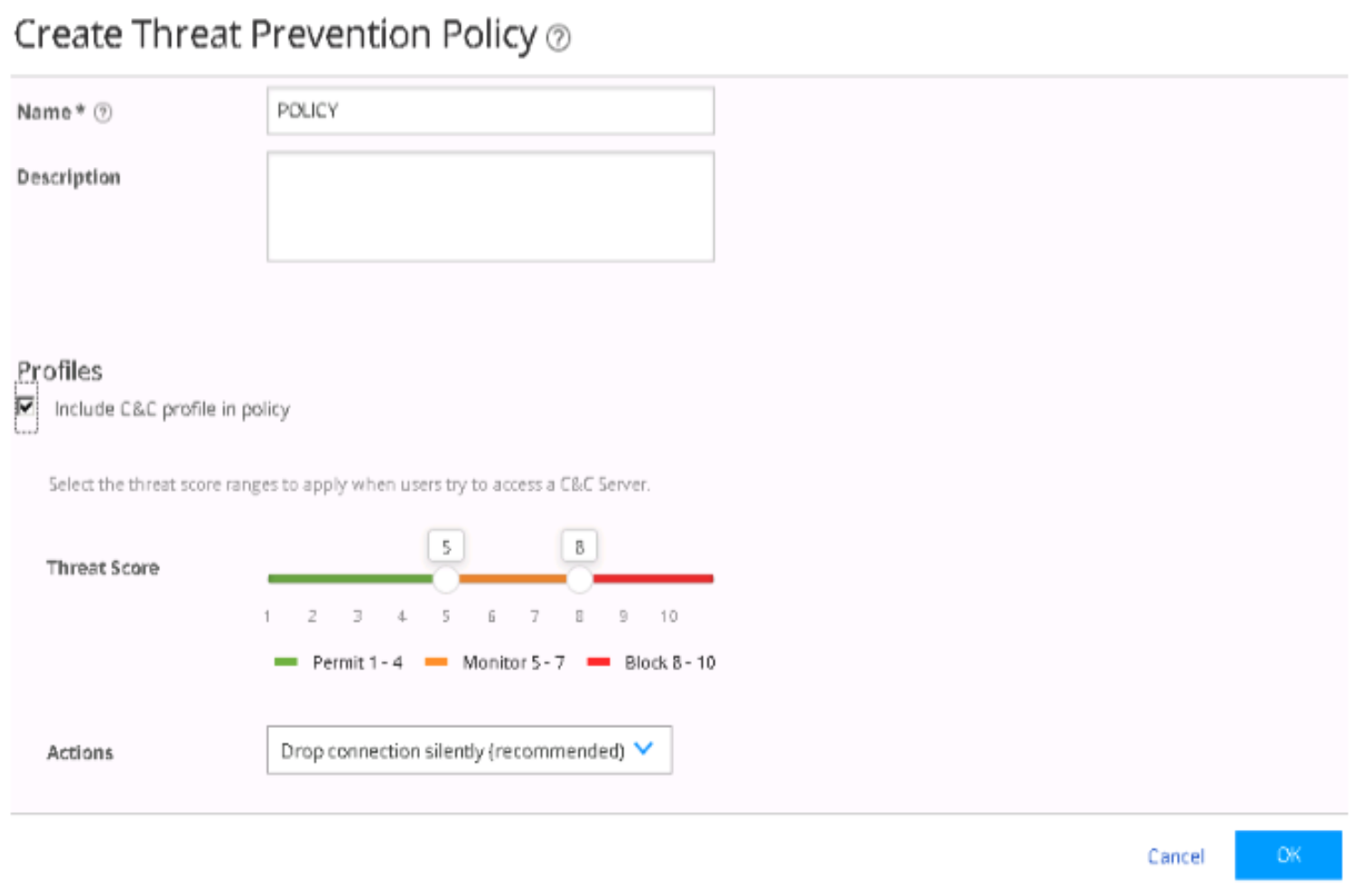
Click OK.
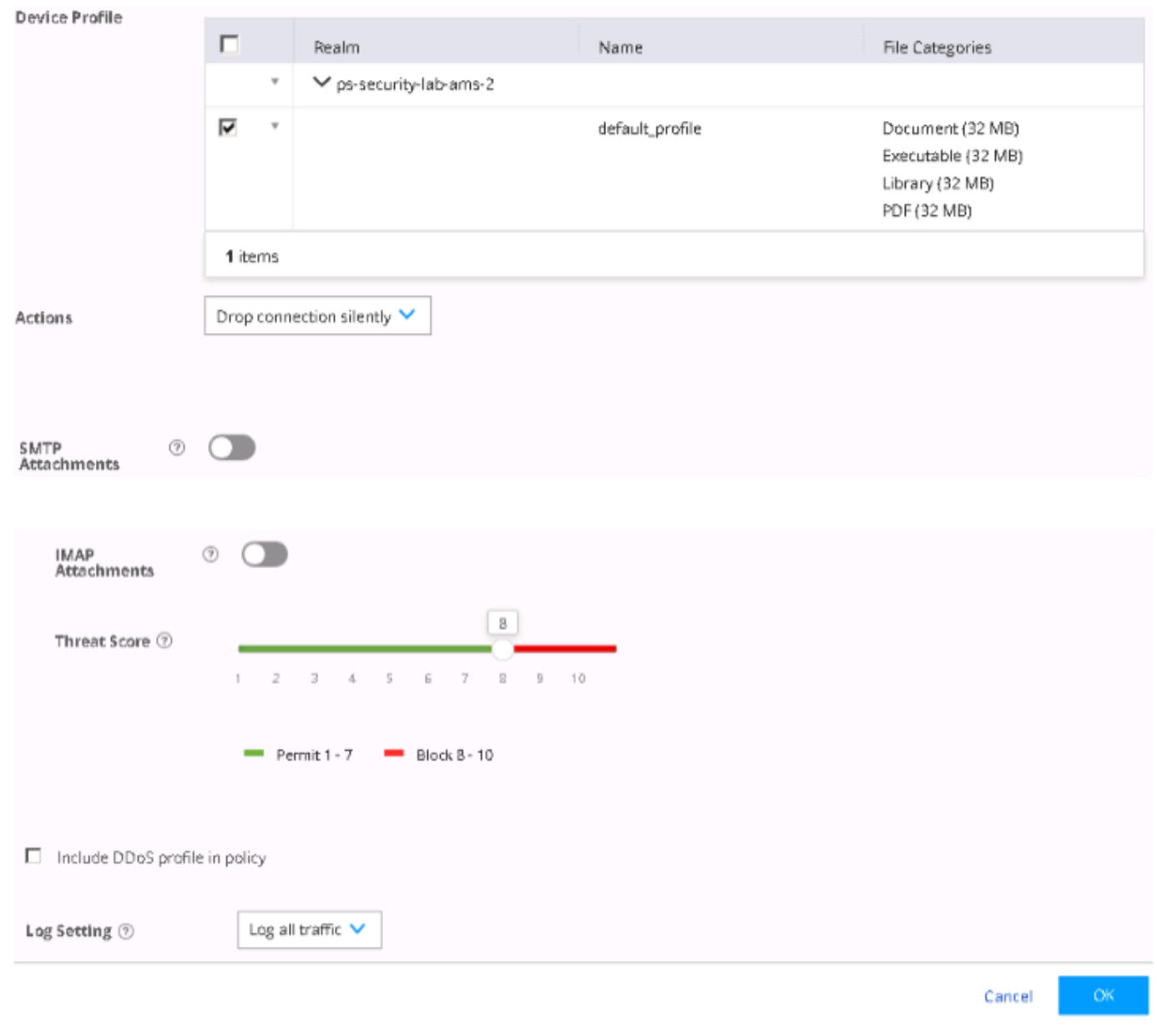
- Threat Prevention Policy needs a profile for HTTP downloads;
this profile indicates what type of files need to be scanned for threats.
To add a profile for HTTP file downloads, in the Device
Profile area, expand the Realm and
select the required profile. Click OK. Figure 66: Threat Prevention Device Profile
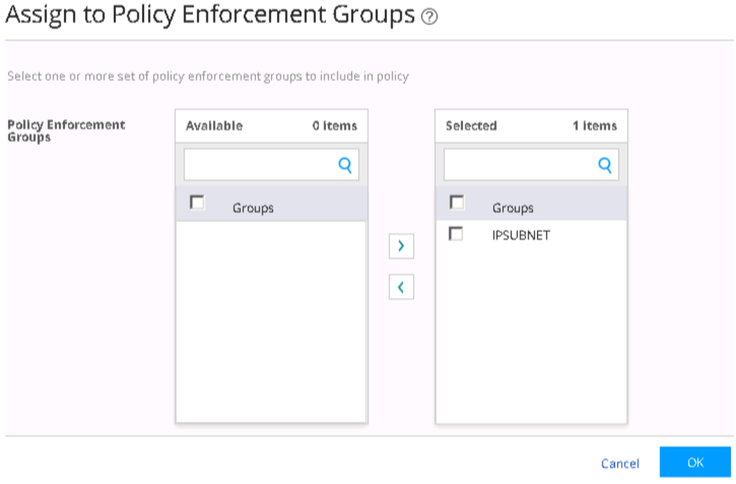
- Assign the threat prevention policy to the desired policy
enforcement group by clicking Assign to Groups. Figure 67: Assigning a Threat Prevention Policy to a Policy Enforcement Group
- Select the policy enforcement group and click OK.Figure 68: Policy Enforcement Group Selection
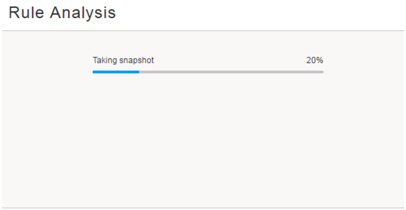
- The system performs a rule analysis, and prepares device
configurations that include the threat prevention policies.Figure 69: Rule Analysis
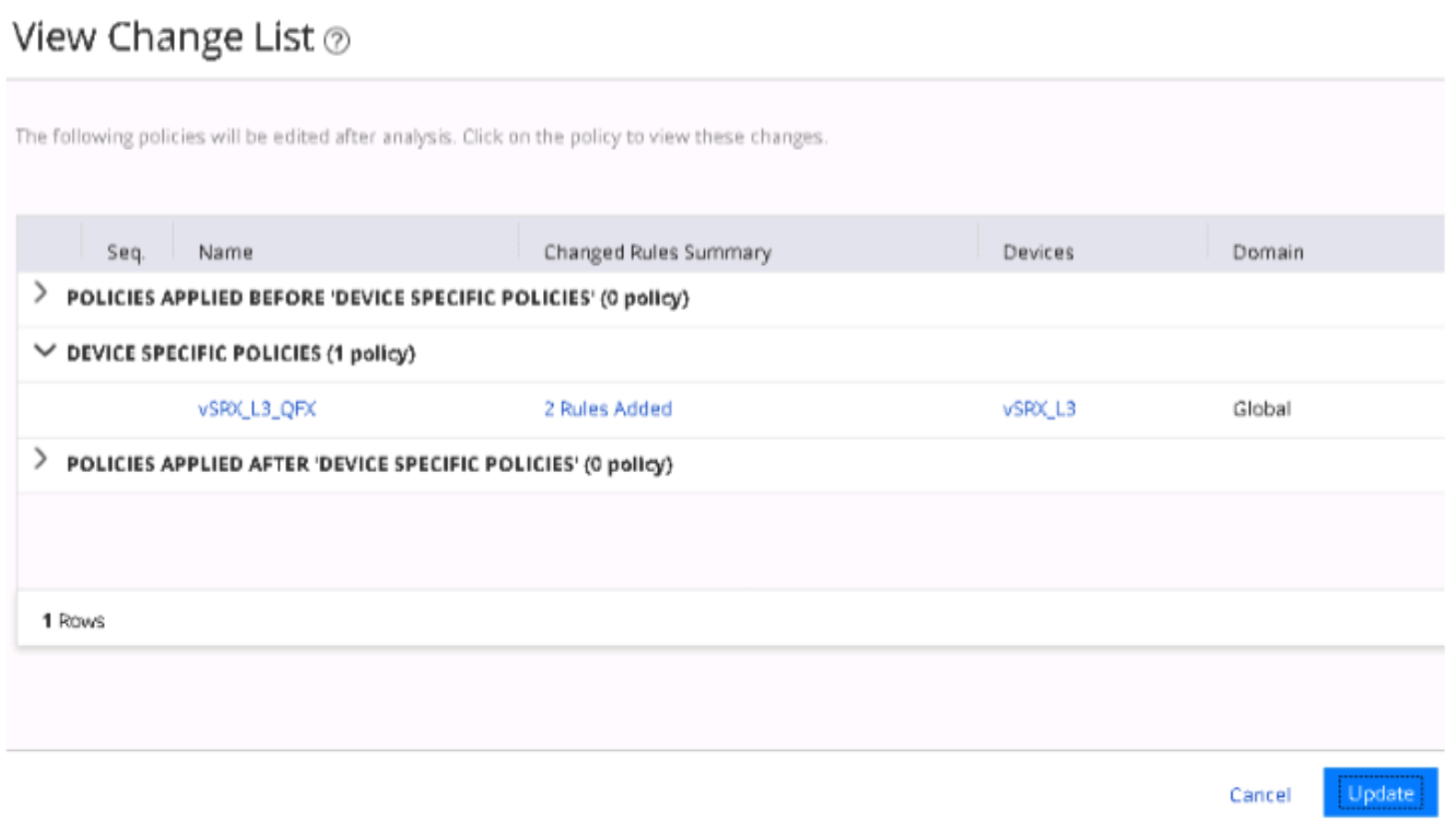
- Once the analysis is complete, instruct the system to
push the updated policy and configuration changes to the SRX Series
device by clicking Update.Figure 70: Updating Policy and Configuration Changes
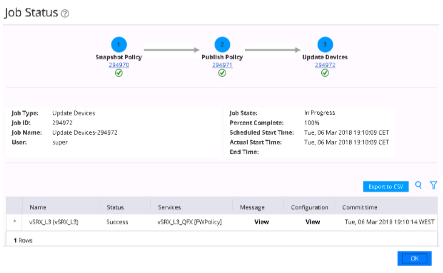
- When the push is complete, the system returns to the Policies page. Click OK.Figure 71: Policy Update Confirmation
 Note:
Note:If the update fails, complete the Threat Prevention Policy Guided Setup. Navigate to Devices > Security Devices and resynchronize your SRX with the network. Then, navigate to Configure > Threat Prevention -> Policies, click Update Required and push the update once again If additional troubleshooting is required, you can view the configuration changes pushed onto an SRX Series device by selecting Monitor > Job Management.
Configuration changes pushed to the SRX device:
Figure 72: SRX Configuration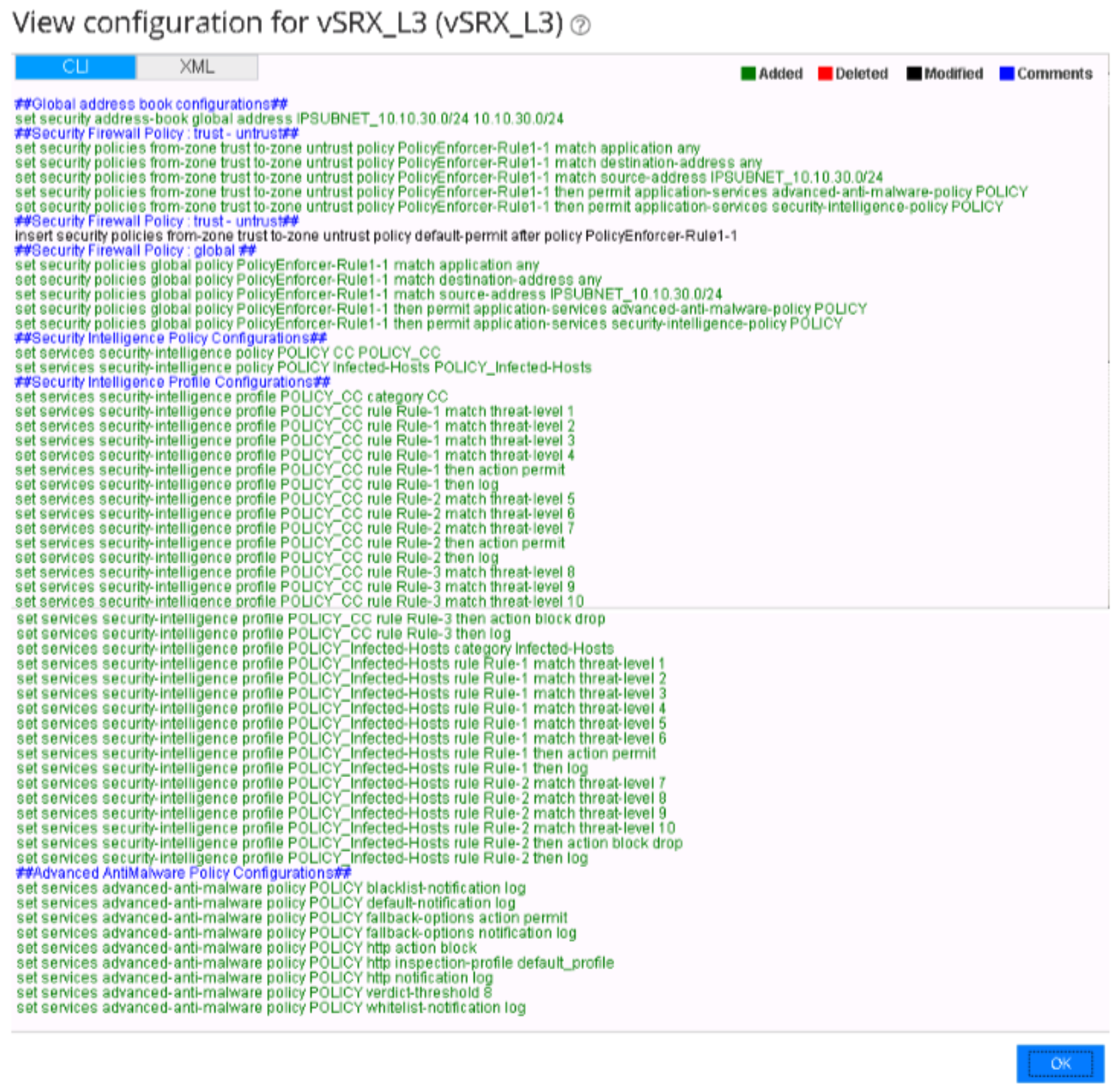
- Click Finish to finalize the Threat
Prevention Policy Guided Setup.Figure 73: Threat Prevent Policy Setup
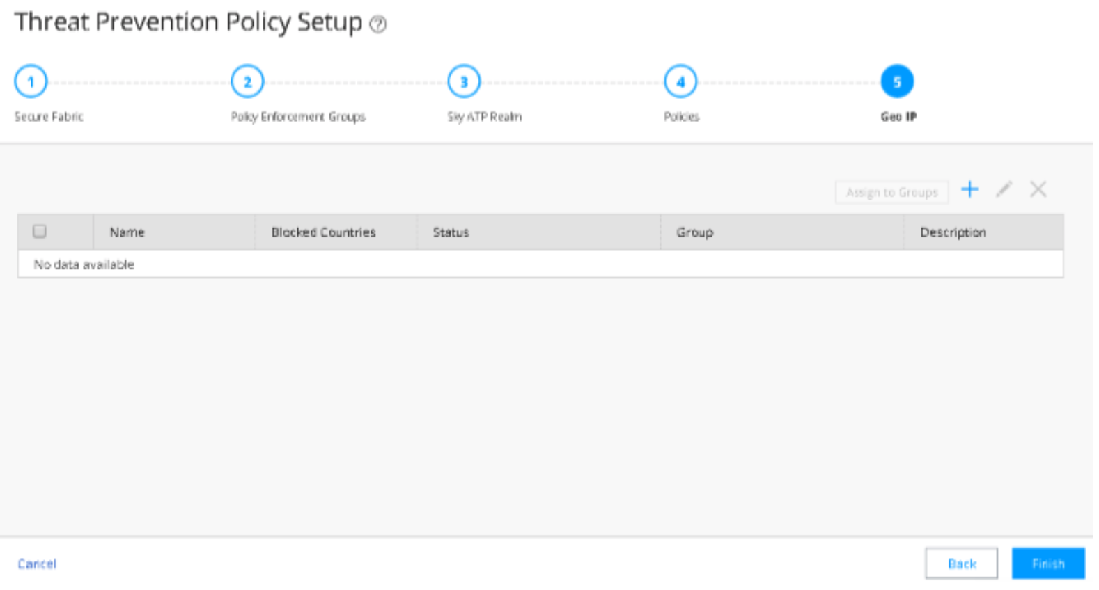
The system displays the summary of the configuration. Click OK.
Figure 74: Threat Prevention Policy Configuration Summary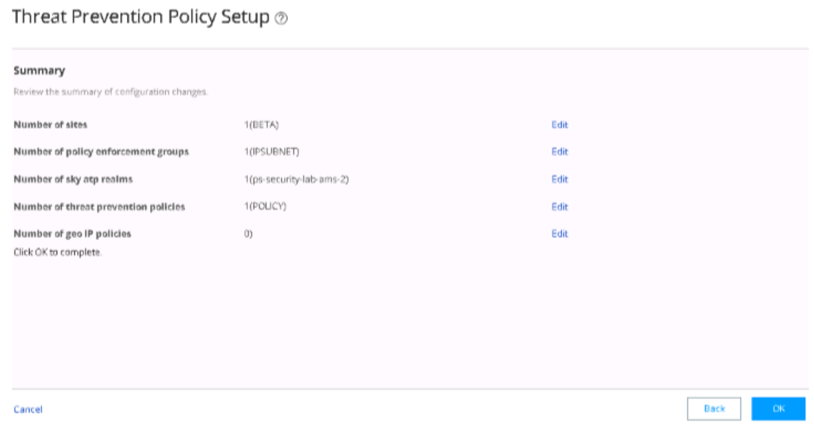
Use Case Verification
To verify the use case configuration, perform the following actions:
- Verify the Enrollment of Devices in ATP Cloud on an SRX Series Device
- Verify the Enrollment of Policy Enforcer and SRX Series Devices in ATP Cloud
- Verify the Enrollment of Devices with ATP Cloud in Security Director
- Verify ForeScout CounterACT Functionality to Block Infected Endpoint (with 802.1X Authentication)
- Verify ForeScout CounterACT Functionality to Quarantine Infected Endpoint (with 802.1X Authentication)
- Verify ForeScout CounterACT Functionality to Block Infected Endpoint (with NETCONF)
- Verify ForeScout CounterACT Functionality to Quarantine Infected Endpoint (with NETCONF)
Verify the Enrollment of Devices in ATP Cloud on an SRX Series Device
Purpose
Verify that the SRX Series device is connected to the ATP Cloud server.
Action
On the SRX device, use the show services advanced-anti-malware
status CLI command.
user@host> show services advanced-anti-malware status
 Server connection status:
  Server hostname: srxapi.eu-west-1.sky.junipersecurity.net
  Server port: 443
    Control Plane:
      Connection time: 2018-02-25 13:37:09 CET
      Connection status: Connected
    Service Plane:
      fpc0
        Connection active number: 1
        Connection retry statistics: 280
Meaning
The CLI output displays the Connection status as Connected. The Server hostname field displays
the ATP Cloud server hostname.
Verify the Enrollment of Policy Enforcer and SRX Series Devices in ATP Cloud
Purpose
Verify that Policy Enforcer and the SRX Series device are enrolled with ATP Cloud.
Action
In ATP Cloud, navigate to the Enrolled Devices page and review the connection information for enrolled devices, including the serial number, model number, tier level (free, basic, premium) enrollment status in ATP Cloud, last telemetry activity, and last activity seen.
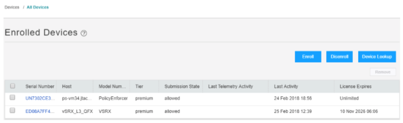
Meaning
The Host field displays details for the enrolled firewall (vSRX_L3_QFX) and for the Policy Enforcer device. You can click the serial numbers for more details.
Verify the Enrollment of Devices with ATP Cloud in Security Director
Purpose
Verify that the SRX Series device enrolled with ATP Cloud in Security Director.
Action
In Security Directory, navigate to Devices > Secure Fabric.
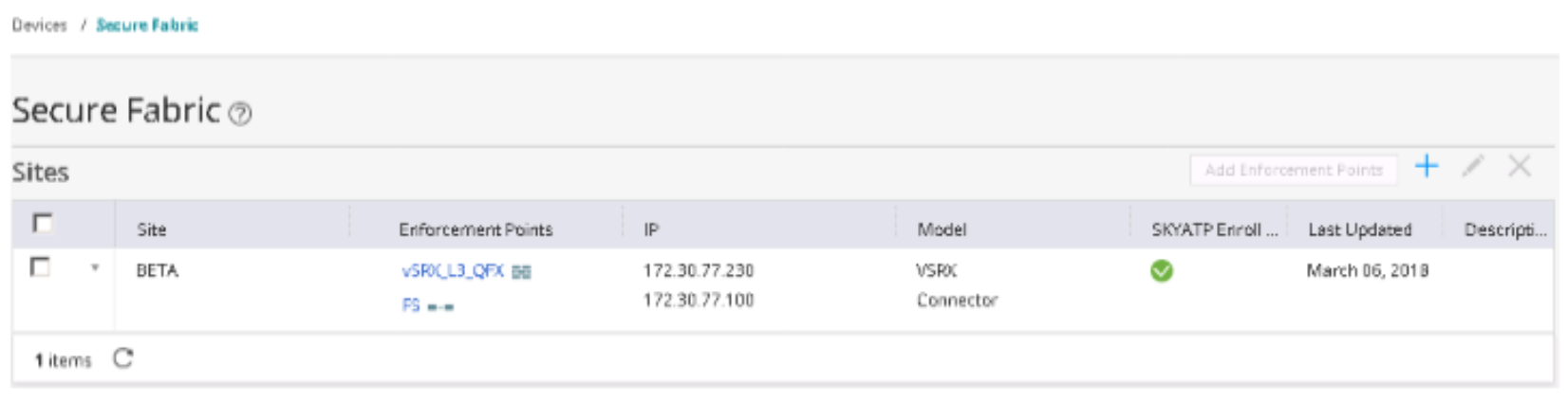
Meaning
A green dot with checkmark displays in the SkyATP Enroll Status field and confirms the enrollment of the SRX Series device with the ATP Cloud realm.
Verify ForeScout CounterACT Functionality to Block Infected Endpoint (with 802.1X Authentication)
Purpose
Test the ForeScout CounterACT integration and functionality when an endpoint is infected. In this example, you verify when the enforcement policy is configured to block the infected host with 802.1X authentication.
Action
A client VM or physical PC is required to trigger an attack.
Before the attack, confirm the following:
Confirm that Windows Supplicant is authenticated and in User VLAN (vlan31).
user@host> show vlans 31
Name		Tag		Interfaces
vlan31		31		ge-0/0/0/18.0*, ge-0/0/0/19.0*

user@host>
Confirm that the endpoint 10.10.30.69 can ping to Internet (IP address 8.8.8.8) and Layer 2 connected default gateway (10.10.30.254). Before the attack, the endpoint starts continuous pings to other endpoints on the LAN and Internet.
The endpoint pings the C&C server on the Internet from Windows Supplicant (in this example from the IP address 184.75.221.43).
Figure 77: Confirming Ping from Windows Supplicant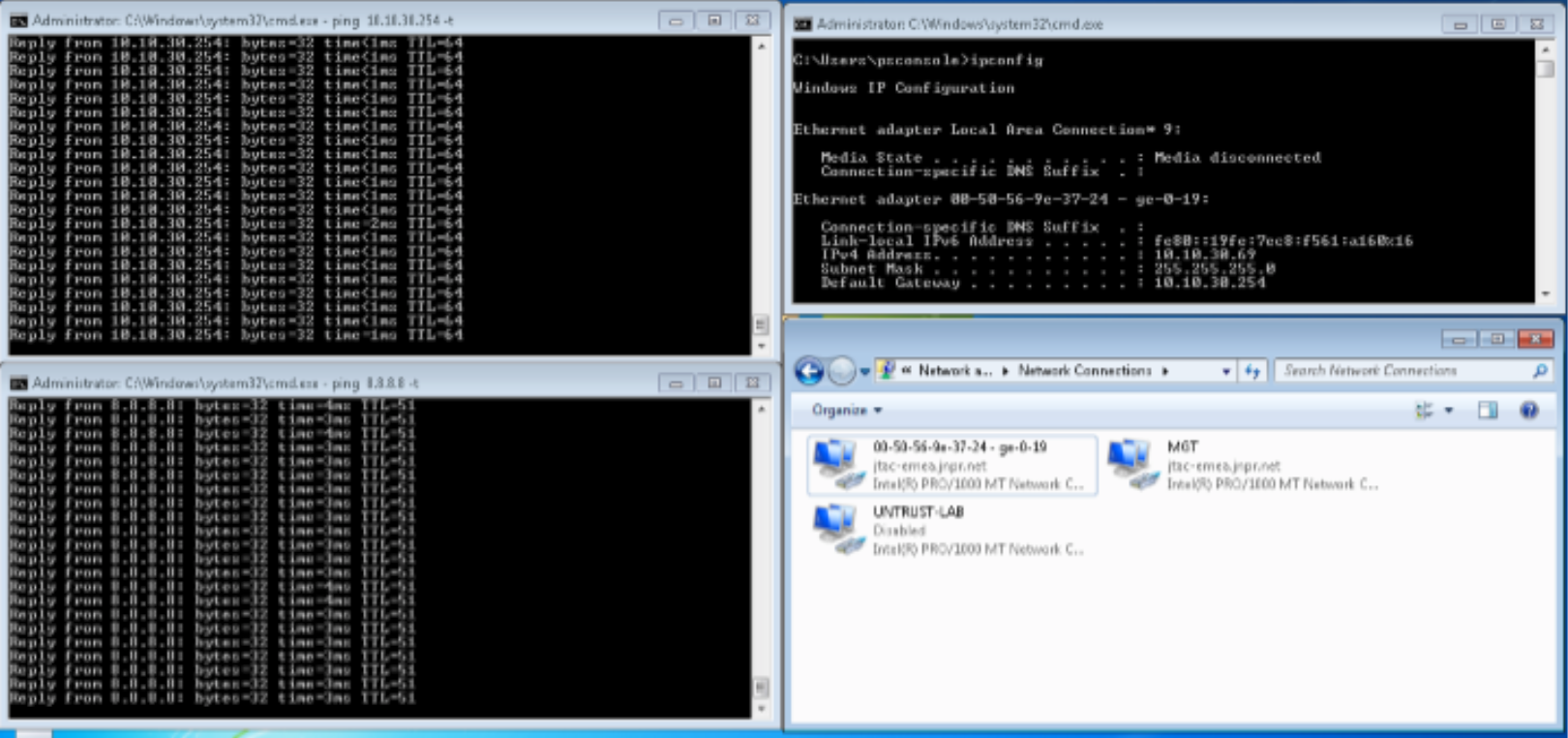
After the attack, the 802.1X session is terminated with RADIUS CoA on the EX4300 switch initiated by ForeScout CounterACT.
Confirm the following:
Confirm that Windows Supplicant cannot connect to the Internet or the LAN anymore.
Figure 78: Confirming Ping from Windows Supplicant is Blocked After the Attack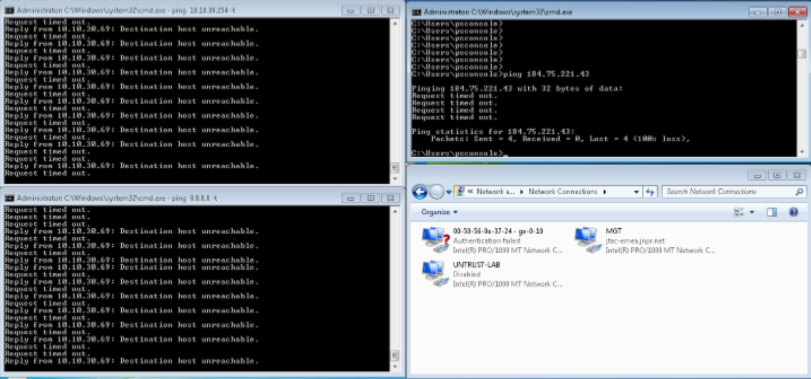
After the RADIUS CoA disconnect message, confirm that the Windows Supplicant is not in User VLAN (vlan31) anymore but in the default VLAN.
Confirm that further authentication requests are rejected by ForeScout CounterACT.
user@host> show vlans default
Name		Tag		Interfaces
default			ge-0/0/0/19.0*
user@host>

user@host> show vlans 31
Name		Tag		Interfaces
vlan31	31		ge-0/0/0/18.0*
user@host>
Confirm the SDSN BLOCK (dot1x) policy match and automated threat remediation action details by navigating to ForeScout CounterACT > Home.
Figure 79: 802.1X SDSN Block Policy Match Verification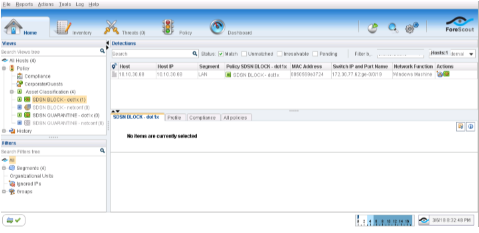
Navigate to Log > Host Log. Review the details for the SDSN BLOCK (dot1x) policy.
Figure 80: 802.1X Host Log
Confirm that the Windows Supplicant’s IP address was also added to the Infected-Hosts Feed on the SRX Series device to block Internet access.
user@vSRX_L3> show security dynamic-address category-name Infected-Hosts
No.		IP-start		IP-end		Feed				Address
1		10.10.30.69	10.10.30.69	Infected-Hosts/1	ID-2150001a
Total number of matching entries: 1
user@vSRX_L3>
In the ATP Cloud portal, navigate to Monitor > Hosts. Confirm the host IP address (10.10.30.69), MAC-ID, and switch port of the Windows Supplicant.
Figure 81: ATP Cloud Host Monitoring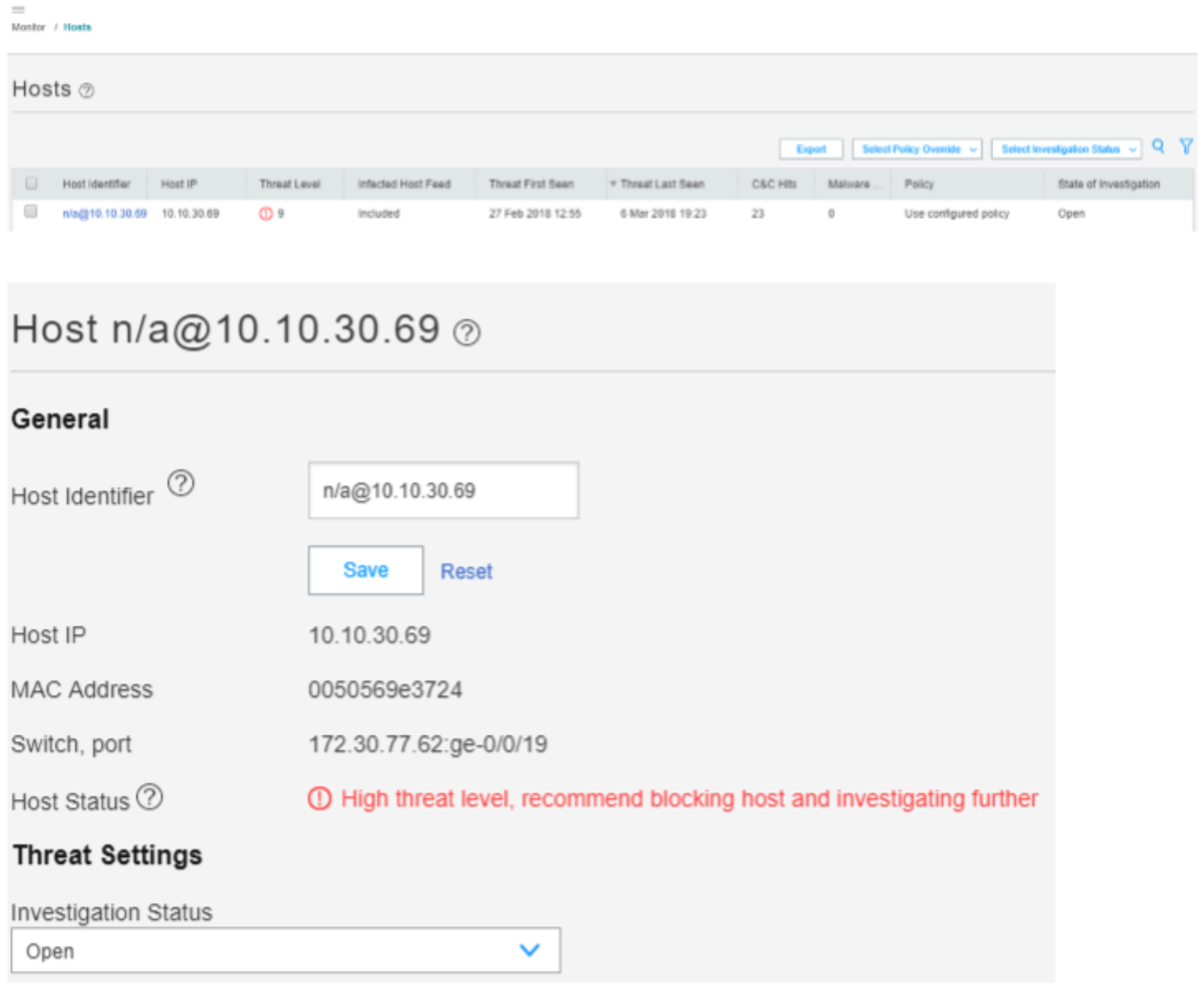
Meaning
All ping sessions show that the traffic is blocked after the threat was detected, confirming that the automated threat remediation use case is working properly.
The Hosts page lists compromised hosts and their associated threat levels. The output confirms that ATP Cloud and Security Director have detected the infected host. You can monitor and mitigate malware detections on a per host basis.
Verify ForeScout CounterACT Functionality to Quarantine Infected Endpoint (with 802.1X Authentication)
Purpose
Test the ForeScout CounterACT integration and functionality when an endpoint is infected. In this example, you verify when the enforcement policy is configured to quarantine the infected host with 802.1X authentication.
Action
A client VM or physical PC is required to trigger an attack.
Before the attack, confirm the following:
Release the infected host on the ATP Cloud portal or in Security Director (Monitor > Threat Prevention > Hosts).
Ensure that Internet or LAN access is restored for the Windows Supplicant.
On the Policy Enforcer > Threat Prevention Policy page, change infected host profile actions to Quarantine and add the VLAN ID as vlan32. Click OK.
Figure 82: Threat Prevention Policy Pre-Attack Configuration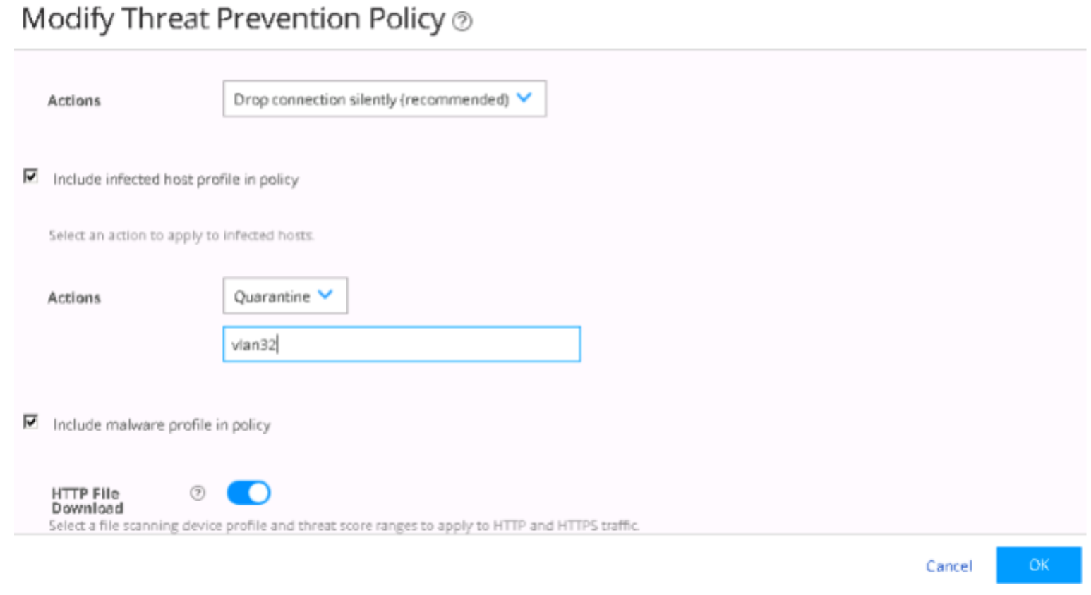
Confirm that Windows Supplicant is authenticated and in User VLAN (vlan31).
user@host> show vlans 31
Name		Tag		Interfaces
vlan31		31		ge-0/0/0/18.0*, ge-0/0/0/19.0*

user@host>
Confirm that the endpoint 10.10.30.69 can ping to Internet (IP address 8.8.8.8) and Layer 2 connected default gateway (10.10.30.254). Before the attack, the endpoint starts continuous pings to other endpoints on the LAN and Internet.
Figure 83: Confirming Ping from Windows Supplication Before the Attack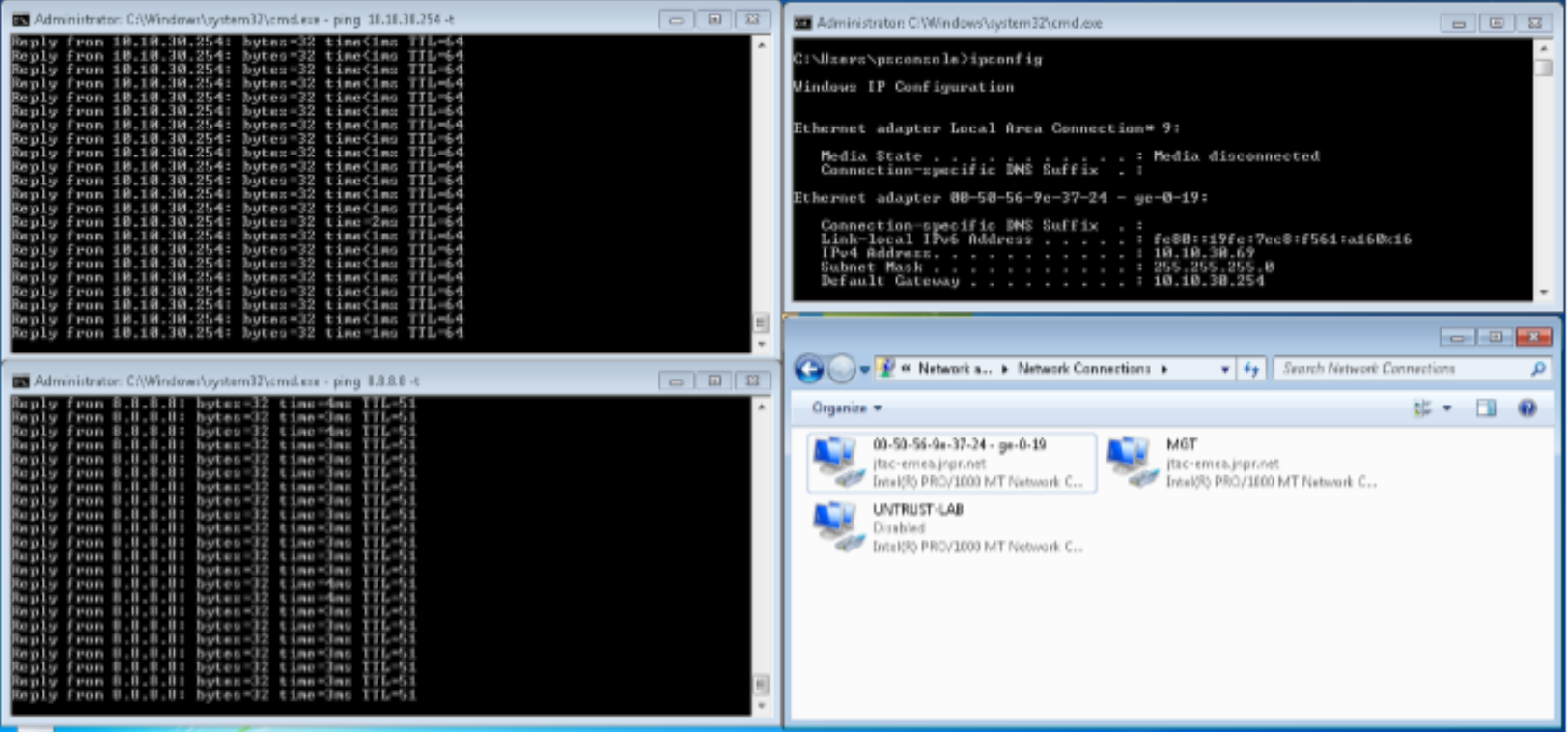
The endpoint pings the C&C server on the Internet from Windows Supplicant (in this example from the IP address 184.75.221.43).
After the attack, the 802.1X session is terminated with RADIUS CoA on the EX4300 switch initiated by ForeScout CounterACT.
Confirm the following:
Confirm that Windows Supplicant re-authenticates and is automatically moved into Quarantine VLAN (vlan32). As a result, the Windows Supplicant cannot connect to the Internet or the LAN anymore.
Figure 84: Confirm Traffic is Moved to Quarantine VLAN After Attack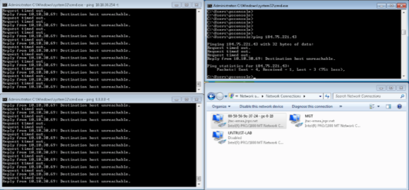
After the RADIUS CoA disconnect message and re-authentication, confirm that the Windows Supplicant is now in Quarantine VLAN (vlan32).
Confirm that further authentication requests are rejected by ForeScout CounterACT.
user@host> show vlans default
Name		Tag		Interfaces
default			ge-0/0/0/19.0*
user@host>

user@host> show vlans 32
Name		Tag		Interfaces
vlan32	32		ge-0/0/0/19.0*
user@host>
Confirm the SDSN QUARANTINE (dot1x) policy match and automated threat remediation action details by navigating to ForeScout CounterACT > Home.
Figure 85: 802.1X SDSN Quarantine Policy Match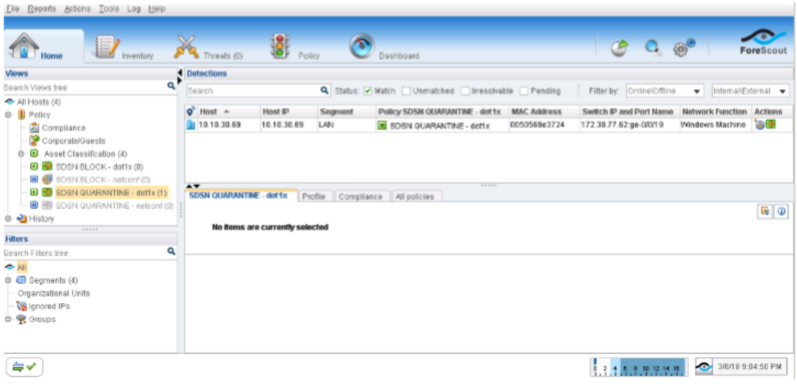
Navigate to Log > Host Log. Review the details for the SDSN QUARANTINE (dot1x) policy.
Figure 86: 802.1X SDSN Quarantine Host Log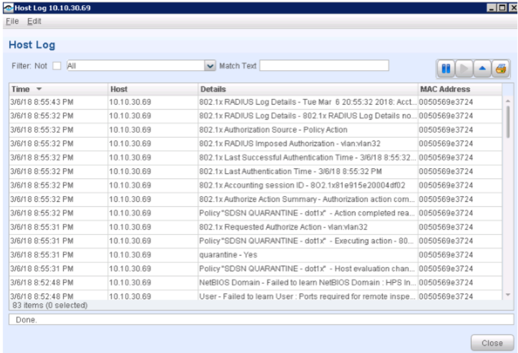
Confirm that the Windows Supplicant’s IP address was also added to the Infected-Hosts Feed on the SRX Series device to block Internet access.
user@vSRX_L3> show security dynamic-address category-name Infected-Hosts
No.		IP-start		IP-end		Feed				Address
1		10.10.30.69	10.10.30.69	Infected-Hosts/1	ID-2150001a
Total number of matching entries: 1
user@vSRX_L3>
In the ATP Cloud portal, navigate to Monitor > Hosts. Confirm the host IP address (10.10.30.69), MAC-ID, and switch port of the Windows Supplicant.
Figure 87: Confirming Host Details in ATP Cloud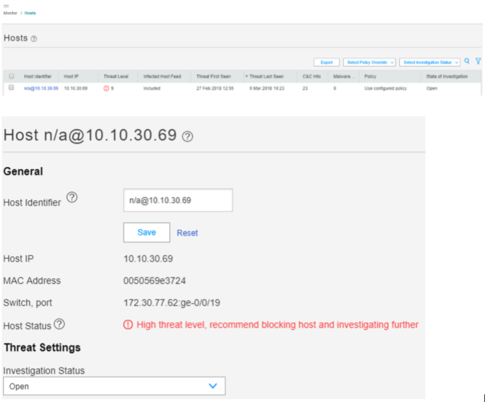
Meaning
The output shows that the ATP Cloud infected host feed containing the Windows Supplicant’s IP address 10.10.30.69 has been successfully downloaded, resulting in the SRX device taking an action to quarantine the IP address.
The Hosts page lists compromised hosts and their associated threat levels. The output confirms that ATP Cloud and Security Director have detected and quarantined the infected host. You can monitor and mitigate malware detections on a per host basis. You can also drill down and verify why the host is marked as infected (for this use case, the C&C server IP address). For malware, details of the downloaded file display.
Verify ForeScout CounterACT Functionality to Block Infected Endpoint (with NETCONF)
Purpose
Test the ForeScout CounterACT integration and functionality when an endpoint is infected. In this example, you verify when the enforcement policy is NETCONF, and it is configured block the infected host.
Action
A client VM or physical PC is required to trigger an attack.
Before the attack, confirm the following:
On the Policy Enforcer > Threat Prevention Policy page, change infected host profile actions to Drop connection silently. Click OK.
Figure 88: Drop Connection Silently Option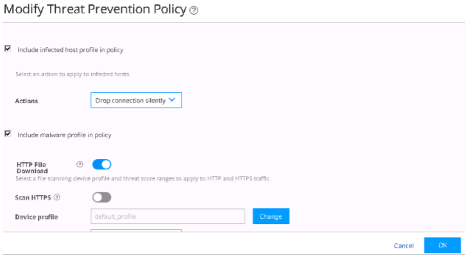
Navigate to the Policies tab. From the Console, stop both SDSN BLOCK–dot1x and SDSN QUARANTINE–dot1x polices, and start both SDSN BLOCK–NETCONF and SDSN QUARANTINE–NETCONF policies.
Figure 89: Policies Tab in Policy Manager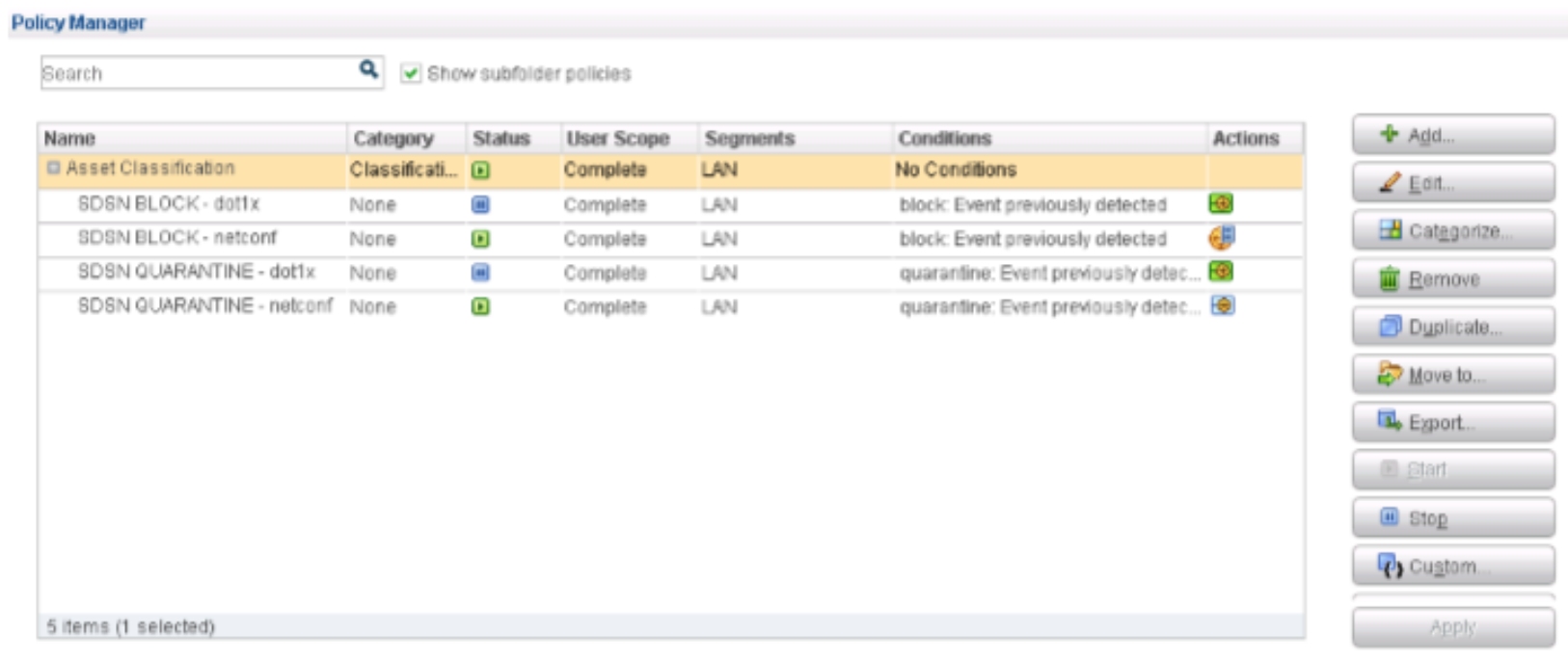
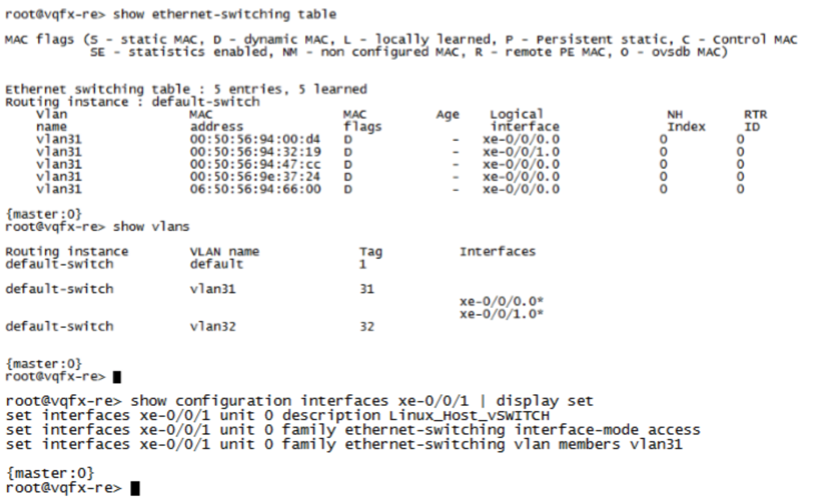
Confirm that the Linux host is in User VLAN (vlan31) with IP address 10.10.30.99.
Figure 90: Linux Host Confirmation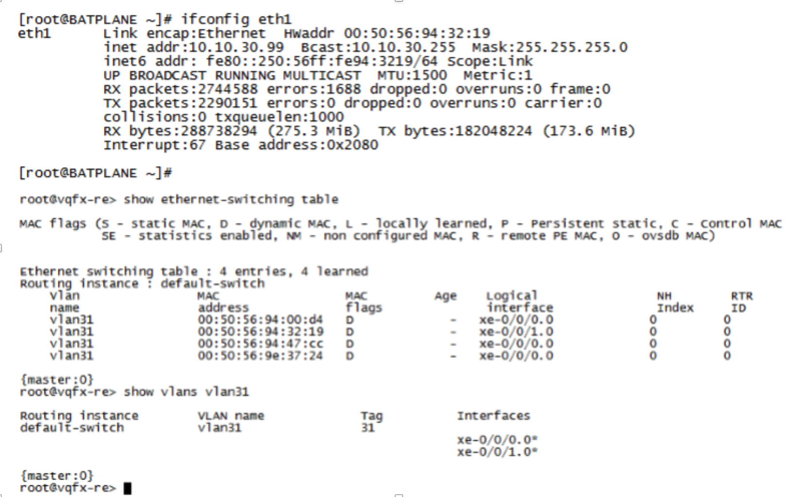
Confirm that the endpoint 10.10.30.99 can ping to Internet (IP address 8.8.8.8) and Layer 2 connected default gateway (10.10.30.254). Before the attack, the endpoint starts continuous pings to other endpoints on the LAN and Internet.
Figure 91: Internet Ping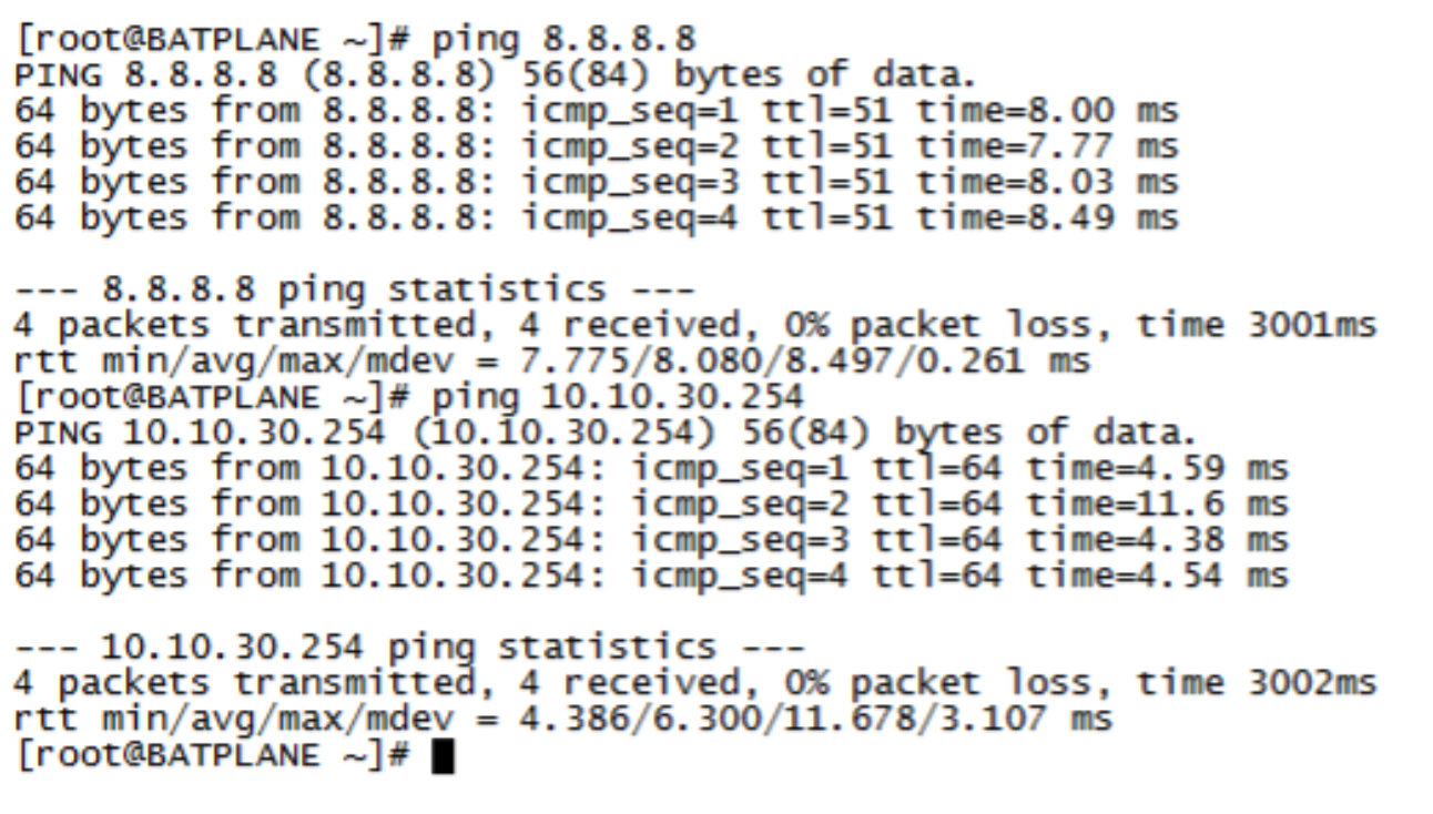
The endpoint pings the C&C server on the Internet from the Linux host (in this example from the IP address 184.75.221.43).
Figure 92: C&C Server Ping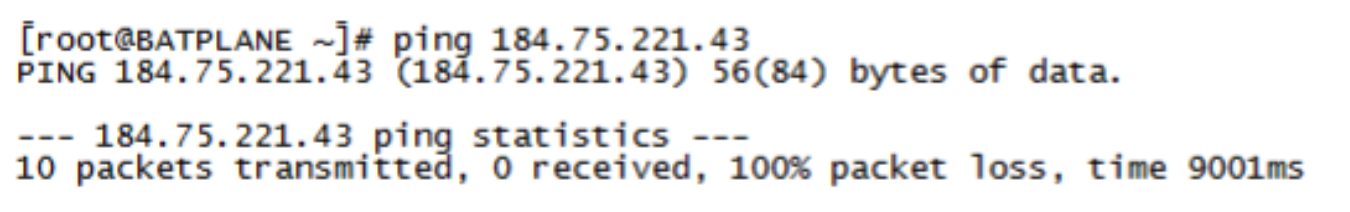
After the attack, ForeScout CounterACT applies ACL on the QFX switch using NETCONF. Confirm the following:
Confirm that the Linux host cannot connect to the Internet or the LAN anymore.
Figure 93: Confirming Disconnected Linux Host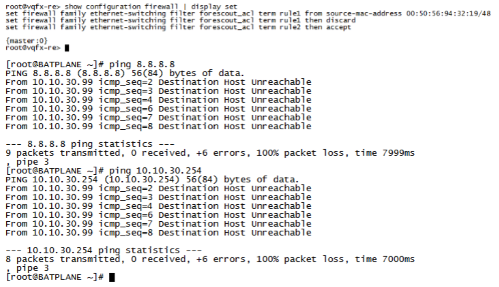
Confirm the SDSN BLOCK (NETCONF) policy match and automated threat remediation action details by navigating to ForeScout CounterACT > Home.
Figure 94: Confirming Policy Match and Automated Threat Remediation Details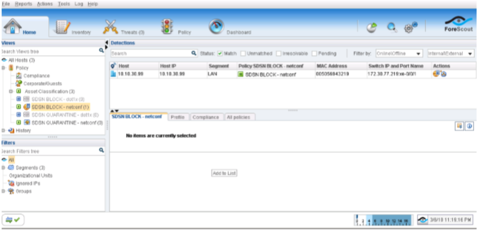
Navigate to Log > Host Log. Review the details for the SDSN BLOCK (NETCONF) policy.
Figure 95: SDSN Block Host Log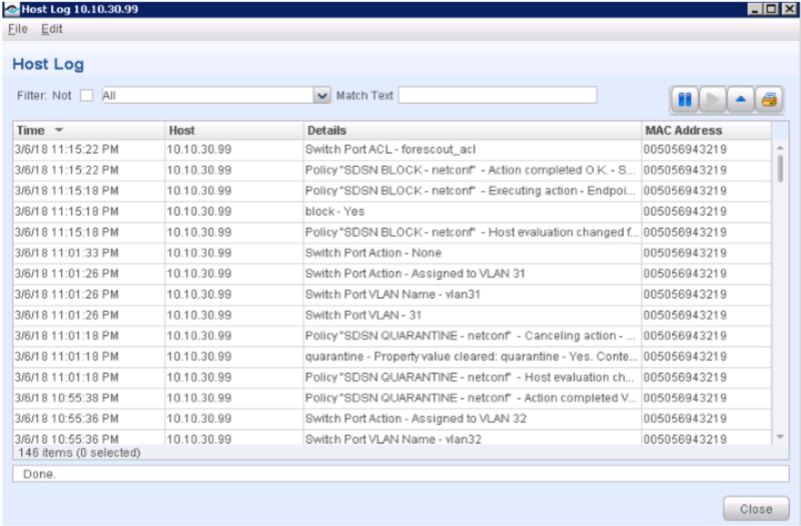
Confirm that the Linux host’s IP address was also added to the Infected-Hosts Feed on the SRX Series device to block Internet access.
user@vSRX_L3> show security dynamic-address category-name Infected-Hosts
No.		IP-start		IP-end		Feed				Address
1		10.10.30.99	10.10.30.99	Infected-Hosts/1	ID-2150001a
Total number of matching entries: 1
user@vSRX_L3>
In the ATP Cloud portal, navigate to Monitor > Hosts. Confirm the host IP address (10.10.30.99), MAC-ID, and switch port of the Linux host.
Figure 96: Confirming Host Information in ATP Cloud Portal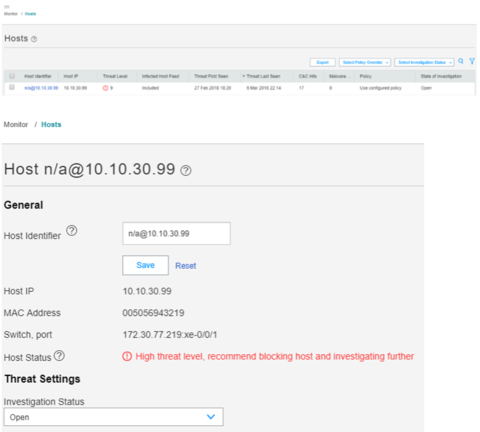
Meaning
All ping sessions show that the traffic is blocked after the threat was detected, confirming that the automated threat remediation use case is working properly.
The Hosts page lists compromised hosts and their associated threat levels. The output confirms that ATP Cloud and Security Director have detected the infected host. You can monitor and mitigate malware detections on a per host basis.
Verify ForeScout CounterACT Functionality to Quarantine Infected Endpoint (with NETCONF)
Purpose
Test the ForeScout CounterACT integration and functionality when an endpoint is infected. In this example, you verify when the enforcement policy NETCONF, and it is configured to quarantine the infected host.
Action
A client VM or physical PC is required to trigger an attack.
Before the attack, confirm the following:
Release the infected host on the ATP Cloud portal or in Security Director (Monitor > Threat Prevention > Hosts).
Ensure that Internet or LAN access is restored for the Linux host.
On the Policy Enforcer > Threat Prevention Policy page, change infected host profile actions to Quarantine and add the VLAN ID as vlan32. Click OK.
Figure 97: Changing Threat Prevention Policy to Quarantine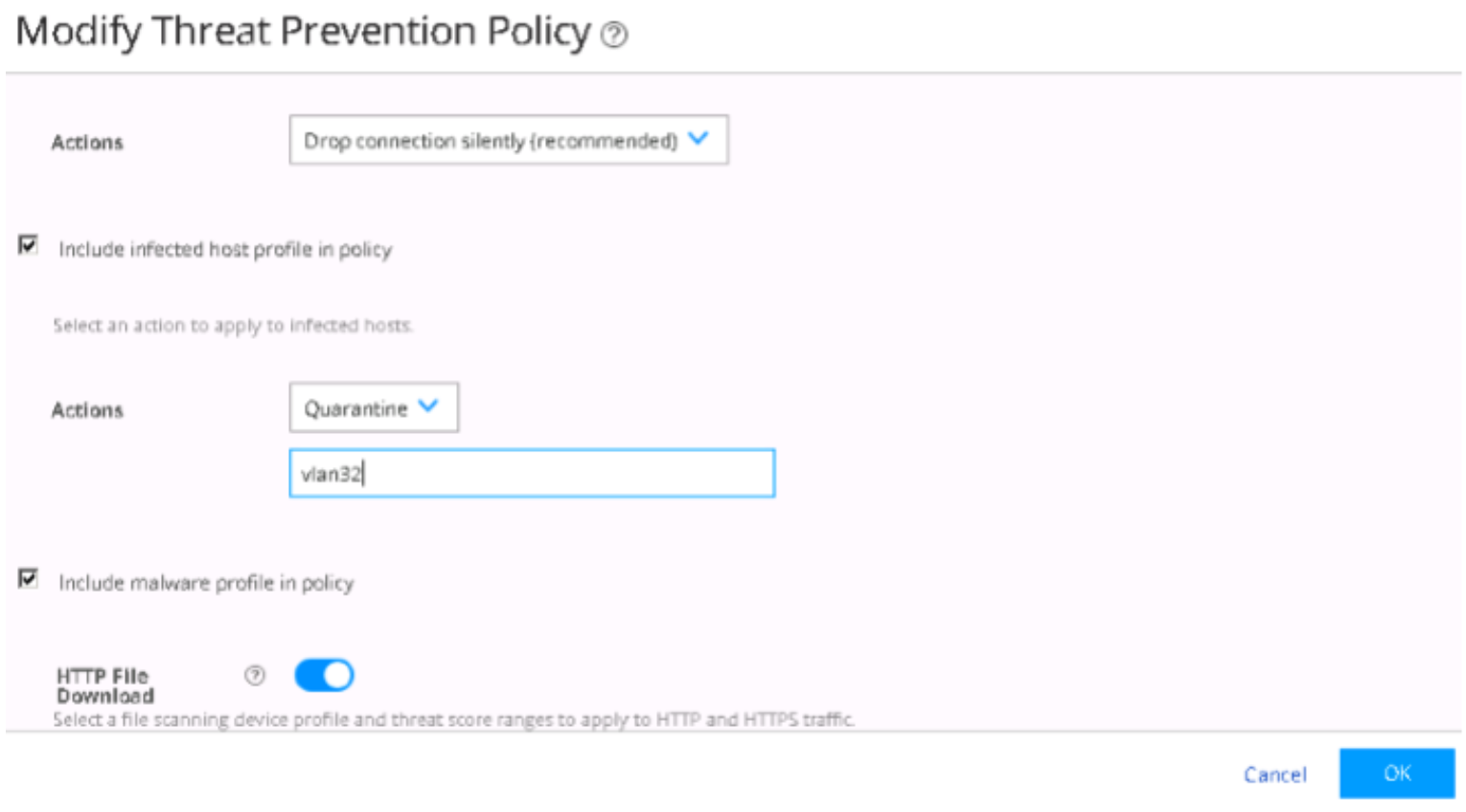
Confirm that the Linux host is in User VLAN (vlan31) with IP address 10.10.30.99.
Figure 98: Confirming Linux Host Details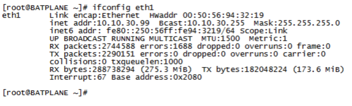
Confirm that the endpoint 10.10.30.99 can ping to Internet (IP address 8.8.8.8) and Layer 2 connected default gateway (10.10.30.254). Before the attack, the endpoint starts continuous pings to other endpoints on the LAN and Internet.
Figure 99: Confirming Internet Connectivity
The endpoint pings the C&C server on the Internet from the Linux host (in this example from the IP address 184.75.221.43).
Figure 100: Confirming Connection to C&C Server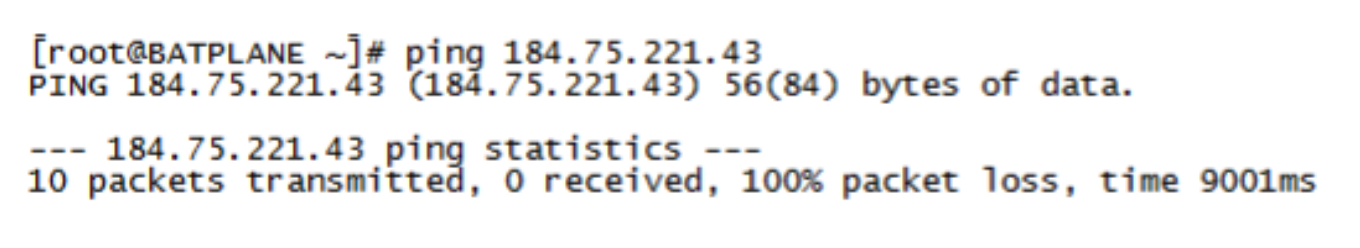
After the attack, ForeScout CounterACT changes the VLAN configuration of the interface connecting the Linux host from User VLAN (vlan31) to Quarantine VLAN (vlan32) on the QFX switch using NETCONF.
Confirm the following:
Confirm that the Linux host cannot connect to the Internet or the LAN anymore.
Figure 101: Confirming Linux Host Cannot Connect to Internet or LAN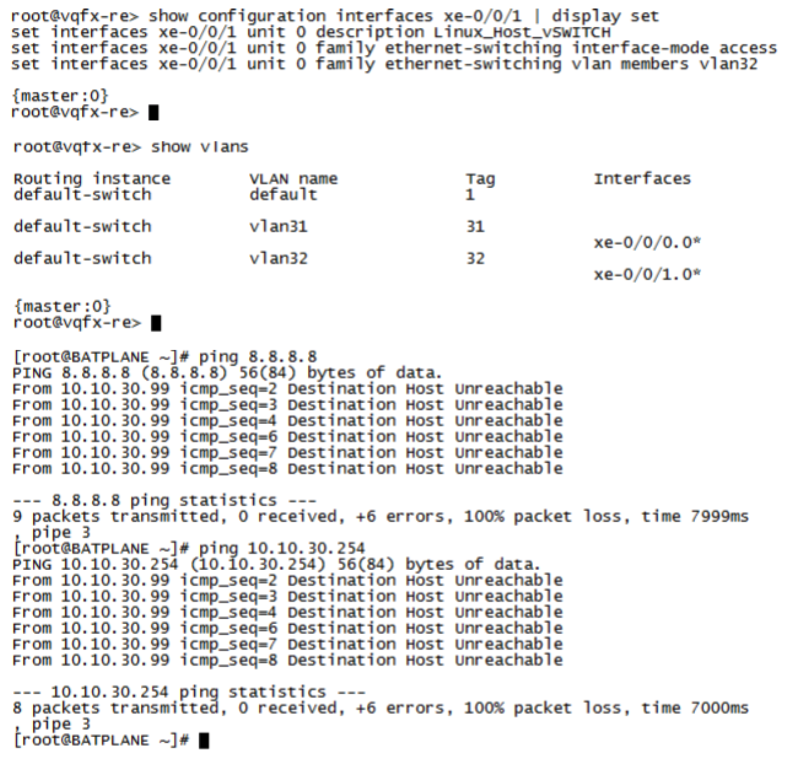
Confirm the SDSN QUARANTINE (NETCONF) policy match and automated threat remediation action details by navigating to ForeScout CounterACT > Home.
Figure 102: Confirming Policy Match and Automated Threat Remediation Details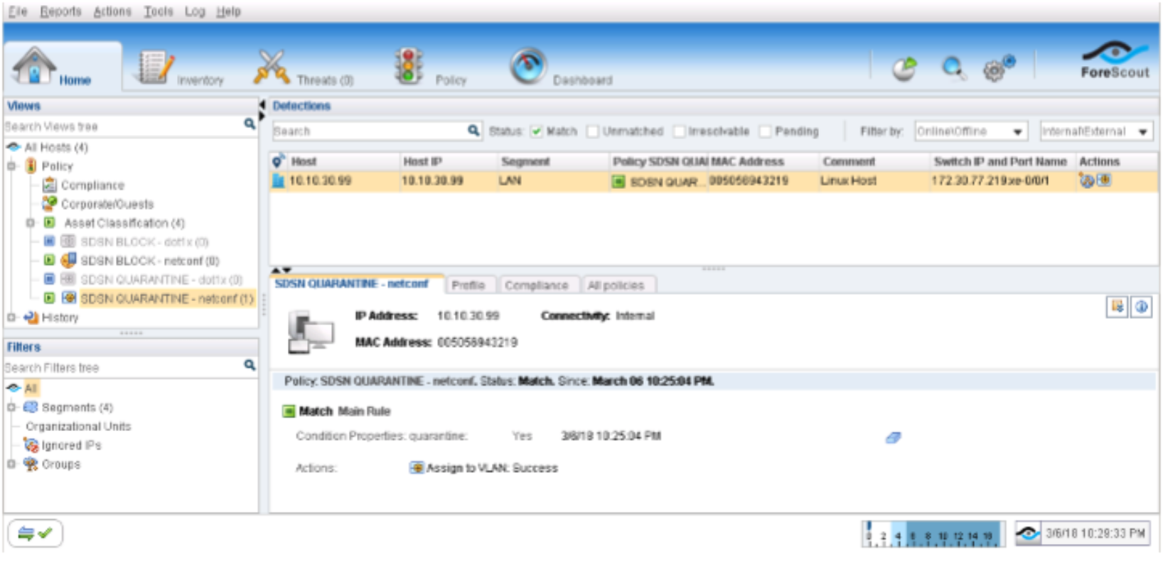
Navigate to Log > Host Log. Review the details for the SDSN BLOCK (NETCONF) policy.
Figure 103: SDSN Block Policy Host Log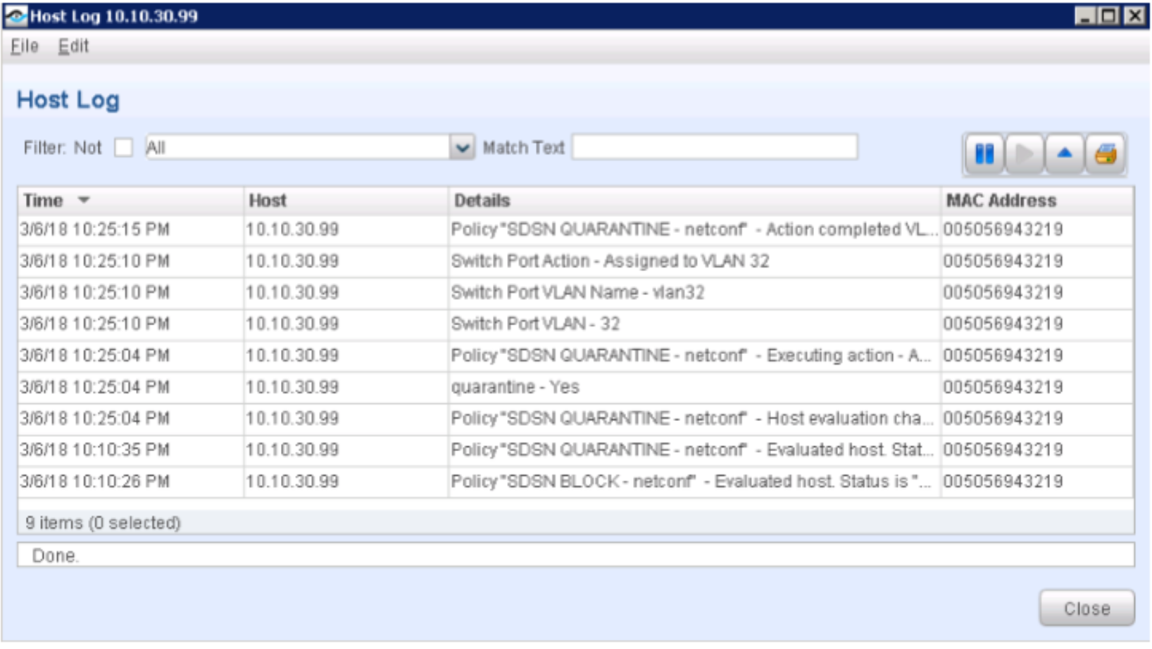
Confirm that the Linux host’s IP address was also added to the Infected-Hosts Feed on the SRX Series device to block Internet access.
user@vSRX_L3> show security dynamic-address category-name Infected-Hosts
No.		IP-start		IP-end		Feed				Address
1		10.10.30.99	10.10.30.99	Infected-Hosts/1	ID-2150001a
Total number of matching entries: 1
user@vSRX_L3>
In the ATP Cloud portal, navigate to Monitor > Hosts. Confirm the host IP address (10.10.30.99), MAC-ID, and switch port of the Linux host.
Figure 104: Confirming Host Details in ATP Cloud Portal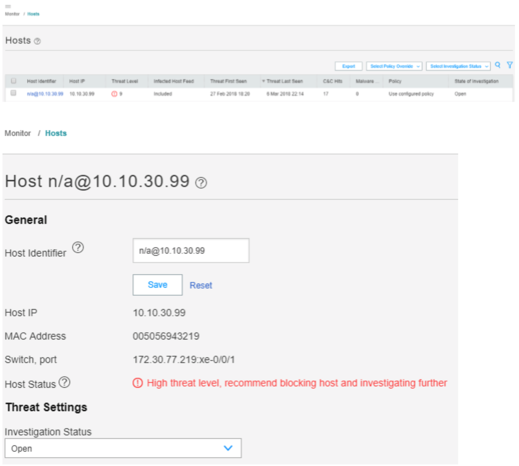
Meaning
The output shows that the ATP Cloud infected host feed containing the Linux host’s IP address 10.10.30.99 has been successfully downloaded, resulting in the SRX device taking an action to quarantine the IP address.
The Hosts page lists compromised hosts and their associated threat levels. The output confirms that ATP Cloud and Security Director have detected and quarantined the infected host. You can monitor and mitigate malware detections on a per host basis.
Appendix A: Device Configurations
This section provides the following device configurations:
- CLI Configuration for SRX Series Device
- CLI Configuration for EX4300 Switch
- CLI Configuration for QFX Switch
CLI Configuration for SRX Series Device
set version 15.1X49-D110.4
set system host-name vSRX_L3
set system time-zone Europe/Amsterdam
set system root-authentication encrypted-password "$ABC123"
set system name-server 172.29.143.60
set system services ssh max-sessions-per-connection 32
set system services netconf ssh
set system services dhcp-local-server group wan-dhcp interface ge-0/0/1.0
set system services web-management http interface fxp0.0
set system syslog user * any emergency
set system syslog file messages any any
set system syslog file messages authorization info
set system syslog file interactive-commands interactive-commands any
set system syslog file default-log-messages any info
set system syslog file default-log-messages match "(requested 'commit' operation)|(requested 'commit synchronize' operation)|(copying configuration to juniper.save)|(commit complete)|ifAdminStatus|(FRU power)|(FRU removal)|(FRU insertion)|(link UP)|transitioned|Transferred|transfer-file|(license add)|(license delete)|(package -X update)|(package -X delete)|(FRU Online)|(FRU Offline)|(plugged in)|(unplugged)|GRES"
set system syslog file default-log-messages structured-data
set system license autoupdate url https://ae1.juniper.net/junos/key_retrieval
set system ntp boot-server 172.30.77.162
set system ntp server 172.30.77.162
set services application-identification
set services ssl initiation profile aamw-ssl trusted-ca aamw-secintel-ca
set services ssl initiation profile aamw-ssl trusted-ca aamw-cloud-ca
set services ssl initiation profile aamw-ssl client-certificate aamw-srx-cert
set services ssl initiation profile aamw-ssl actions crl disable
set services security-intelligence url https://172.30.77.104:443/api/v1/manifest.xml
set services security-intelligence authentication auth-token 22QDFN29DJQXK7ZD3V8Q21X34THWKBC7
set services security-intelligence profile POLICY_CC category CC
set services security-intelligence profile POLICY_CC rule Rule-1 match threat-level 1
set services security-intelligence profile POLICY_CC rule Rule-1 match threat-level 2
set services security-intelligence profile POLICY_CC rule Rule-1 match threat-level 3
set services security-intelligence profile POLICY_CC rule Rule-1 match threat-level 4
set services security-intelligence profile POLICY_CC rule Rule-1 then action permit
set services security-intelligence profile POLICY_CC rule Rule-1 then log
set services security-intelligence profile POLICY_CC rule Rule-2 match threat-level 5
set services security-intelligence profile POLICY_CC rule Rule-2 match threat-level 6
set services security-intelligence profile POLICY_CC rule Rule-2 match threat-level 7
set services security-intelligence profile POLICY_CC rule Rule-2 then action permit
set services security-intelligence profile POLICY_CC rule Rule-2 then log
set services security-intelligence profile POLICY_CC rule Rule-3 match threat-level 8
set services security-intelligence profile POLICY_CC rule Rule-3 match threat-level 9
set services security-intelligence profile POLICY_CC rule Rule-3 match threat-level 10
set services security-intelligence profile POLICY_CC rule Rule-3 then action block drop
set services security-intelligence profile POLICY_CC rule Rule-3 then log
set services security-intelligence profile POLICY_Infected-Hosts category Infected-Hosts
set services security-intelligence profile POLICY_Infected-Hosts rule Rule-1 match threat-level 1
set services security-intelligence profile POLICY_Infected-Hosts rule Rule-1 match threat-level 2
set services security-intelligence profile POLICY_Infected-Hosts rule Rule-1 match threat-level 3
set services security-intelligence profile POLICY_Infected-Hosts rule Rule-1 match threat-level 4
set services security-intelligence profile POLICY_Infected-Hosts rule Rule-1 match threat-level 5
set services security-intelligence profile POLICY_Infected-Hosts rule Rule-1 match threat-level 6
set services security-intelligence profile POLICY_Infected-Hosts rule Rule-1 then action permit
set services security-intelligence profile POLICY_Infected-Hosts rule Rule-1 then log
set services security-intelligence profile POLICY_Infected-Hosts rule Rule-2 match threat-level 7
set services security-intelligence profile POLICY_Infected-Hosts rule Rule-2 match threat-level 8
set services security-intelligence profile POLICY_Infected-Hosts rule Rule-2 match threat-level 9
set services security-intelligence profile POLICY_Infected-Hosts rule Rule-2 match threat-level 10
set services security-intelligence profile POLICY_Infected-Hosts rule Rule-2 then action block drop
set services security-intelligence profile POLICY_Infected-Hosts rule Rule-2 then log
set services security-intelligence policy POLICY CC POLICY_CC
set services security-intelligence policy POLICY Infected-Hosts POLICY_Infected-Hosts
set services advanced-anti-malware connection url https://srxapi.eu-west-1.sky.junipersecurity.net
set services advanced-anti-malware connection authentication tls-profile aamw-ssl
set services advanced-anti-malware policy POLICY http inspection-profile default_profile
set services advanced-anti-malware policy POLICY http action block
set services advanced-anti-malware policy POLICY http notification log
set services advanced-anti-malware policy POLICY verdict-threshold 8
set services advanced-anti-malware policy POLICY fallback-options action permit
set services advanced-anti-malware policy POLICY fallback-options notification log
set services advanced-anti-malware policy POLICY default-notification log
set services advanced-anti-malware policy POLICY whitelist-notification log
set services advanced-anti-malware policy POLICY blacklist-notification log
set security log mode stream
set security log format sd-syslog
set security log report
set security log source-address 10.10.10.251
set security log stream TRAFFIC category all
set security log stream TRAFFIC host 10.10.10.250
set security log stream TRAFFIC host port 514
set security pki ca-profile aamw-ca ca-identity deviceCA
set security pki ca-profile aamw-ca enrollment url http://ca.junipersecurity.net:8080/ejbca/publicweb/apply/scep/SRX/pkiclient.exe
set security pki ca-profile aamw-ca revocation-check disable
set security pki ca-profile aamw-ca revocation-check crl url http://va.junipersecurity.net/ca/deviceCA.crl
set security pki ca-profile aamw-secintel-ca ca-identity JUNIPER
set security pki ca-profile aamw-secintel-ca revocation-check crl url http://va.junipersecurity.net/ca/current.crl
set security pki ca-profile aamw-cloud-ca ca-identity JUNIPER_CLOUD
set security pki ca-profile aamw-cloud-ca revocation-check crl url http://va.junipersecurity.net/ca/cloudCA.crl
set security address-book global address IPSUBNET_10.10.30.0/24 10.10.30.0/24
set security screen ids-option untrust-screen icmp ping-death
set security screen ids-option untrust-screen ip source-route-option
set security screen ids-option untrust-screen ip tear-drop
set security screen ids-option untrust-screen tcp syn-flood alarm-threshold 1024
set security screen ids-option untrust-screen tcp syn-flood attack-threshold 200
set security screen ids-option untrust-screen tcp syn-flood source-threshold 1024
set security screen ids-option untrust-screen tcp syn-flood destination-threshold 2048
set security screen ids-option untrust-screen tcp syn-flood queue-size 2000
set security screen ids-option untrust-screen tcp syn-flood timeout 20
set security screen ids-option untrust-screen tcp land
set security nat source rule-set OutBoundInternetTraffic from zone trust
set security nat source rule-set OutBoundInternetTraffic to zone untrust
set security nat source rule-set OutBoundInternetTraffic rule natALL match source-address 0.0.0.0/0
set security nat source rule-set OutBoundInternetTraffic rule natALL match destination-address 0.0.0.0/0
set security nat source rule-set OutBoundInternetTraffic rule natALL then source-nat interface
set security policies from-zone trust to-zone untrust policy PolicyEnforcer-Rule1-1 match source-address IPSUBNET_10.10.30.0/24
set security policies from-zone trust to-zone untrust policy PolicyEnforcer-Rule1-1 match destination-address any
set security policies from-zone trust to-zone untrust policy PolicyEnforcer-Rule1-1 match application any
set security policies from-zone trust to-zone untrust policy PolicyEnforcer-Rule1-1 then permit applicationservices security-intelligence-policy POLICY
set security policies from-zone trust to-zone untrust policy PolicyEnforcer-Rule1-1 then permit applicationservices advanced-anti-malware-policy POLICY
set security policies from-zone trust to-zone untrust policy default-permit match source-address any
set security policies from-zone trust to-zone untrust policy default-permit match destination-address any
set security policies from-zone trust to-zone untrust policy default-permit match application any
set security policies from-zone trust to-zone untrust policy default-permit then permit
set security policies global policy PolicyEnforcer-Rule1-1 match source-address IPSUBNET_10.10.30.0/24
set security policies global policy PolicyEnforcer-Rule1-1 match destination-address any
set security policies global policy PolicyEnforcer-Rule1-1 match application any
set security policies global policy PolicyEnforcer-Rule1-1 then permit application-services securityintelligence-policy POLICY
set security policies global policy PolicyEnforcer-Rule1-1 then permit application-services advanced-antimalware-policy POLICY
set security zones security-zone trust tcp-rst
set security zones security-zone trust host-inbound-traffic system-services all
set security zones security-zone trust host-inbound-traffic protocols all
set security zones security-zone trust interfaces ge-0/0/1.0
set security zones security-zone untrust screen untrust-screen
set security zones security-zone untrust host-inbound-traffic system-services all
set security zones security-zone untrust host-inbound-traffic protocols all
set security zones security-zone untrust interfaces ge-0/0/2.0
set security zones security-zone untrust interfaces ge-0/0/0.0
set interfaces ge-0/0/0 description LOGGING-INTERFACE-VLAN10
set interfaces ge-0/0/0 unit 0 family inet address 10.10.10.251/24
set interfaces ge-0/0/1 description LAN-VLAN31
set interfaces ge-0/0/1 vlan-tagging
set interfaces ge-0/0/1 unit 0 vlan-id 31
set interfaces ge-0/0/1 unit 0 family inet address 10.10.30.254/24
set interfaces ge-0/0/2 description INTERNET-MANAGEMENT
set interfaces ge-0/0/2 unit 0 family inet address 172.30.77.230/23
set interfaces fxp0 unit 0
deactivate interfaces fxp0
set snmp trap-group space targets 172.30.77.106
set routing-options static route 0.0.0.0/0 next-hop 172.30.77.1
set access address-assignment pool wan-1 family inet network 10.10.30.0/24
set access address-assignment pool wan-1 family inet range wan-1-range low 10.10.30.60
set access address-assignment pool wan-1 family inet range wan-1-range high 10.10.30.100
set access address-assignment pool wan-1 family inet dhcp-attributes maximum-lease-time 86400
set access address-assignment pool wan-1 family inet dhcp-attributes name-server 8.8.8.8
set access address-assignment pool wan-1 family inet dhcp-attributes name-server 172.30.77.162
set access address-assignment pool wan-1 family inet dhcp-attributes router 10.10.30.254
CLI Configuration for EX4300 Switch
set version 15.1R5.5
set system host-name abernathy
set system services ssh root-login allow
set system services ssh protocol-version v2
set system services ssh max-sessions-per-connection 32
set system services netconf ssh
set system ntp server 172.30.255.62
set interfaces ge-0/0/1 description PORT_TO_ESXi_vmnic0_vSRX_LOGGING
set interfaces ge-0/0/1 unit 0 family ethernet-switching port-mode trunk
set interfaces ge-0/0/1 unit 0 family ethernet-switching vlan members LOGGING
set interfaces ge-0/0/18 description PORT_TO_ESXi_vmnic1_vSRX_vQFX_LAN
set interfaces ge-0/0/18 unit 0 family ethernet-switching port-mode trunk
set interfaces ge-0/0/18 unit 0 family ethernet-switching vlan members vlan31
set interfaces ge-0/0/19 description PORT_TO_ESXi_vmnic2_WINDOWS7_DOT1x
set interfaces ge-0/0/19 unit 0 family ethernet-switching port-mode access
set interfaces ge-0/0/19 unit 0 family ethernet-switching vlan members default
set interfaces ge-0/0/20 description SPAN_PORT_TO_ESXi_vmnic3_COUNTERACT_EXPERIMENTAL
set interfaces ge-0/0/20 unit 0 family ethernet-switching port-mode access
set interfaces ge-0/0/20 unit 0 family ethernet-switching vlan members default
set interfaces me0 unit 0 family inet address 172.30.77.62/23
set routing-options static route 0.0.0.0/0 next-hop 172.30.77.1
set protocols igmp
set protocols dot1x authenticator authentication-profile-name CounterACT
set protocols dot1x authenticator interface ge-0/0/19.0 supplicant multiple
set protocols rstp
set access radius-server 172.30.77.100 dynamic-request-port 3799
set access radius-server 172.30.77.100 secret "$ABC123"
set access radius-server 172.30.77.100 source-address 172.30.77.62
set access profile CounterACT authentication-order radius
set access profile CounterACT radius authentication-server 172.30.77.100
set access profile CounterACT radius accounting-server 172.30.77.100
set access profile CounterACT radius options nas-identifier 172.30.77.100
set access profile CounterACT accounting order radius
set ethernet-switching-options analyzer mirror_traffic input ingress interface ge-0/0/18.0
set ethernet-switching-options analyzer mirror_traffic input ingress interface ge-0/0/19.0
set ethernet-switching-options analyzer mirror_traffic input egress interface ge-0/0/18.0
set ethernet-switching-options analyzer mirror_traffic input egress interface ge-0/0/19.0
set ethernet-switching-options analyzer mirror_traffic output interface ge-0/0/20.0
set ethernet-switching-options secure-access-port vlan vlan31 examine-dhcp
set vlans LOGGING description LOGGING
set vlans LOGGING vlan-id 10
set vlans vlan31 description LAN-VLAN31
set vlans vlan31 vlan-id 31
set vlans vlan32 description QUARANTINE
set vlans vlan32 vlan-id 32
set poe interface all
CLI Configuration for QFX Switch
set system host-name vqfx-re
set system root-authentication encrypted-password "$ABC123"
set system root-authentication ssh-rsa "ssh-rsa AAAAB3NzaC1yc2EAAAABIwAAAQEA6NF8iallvQVp22WDkTkyrtvp9eWW6A8YVr+kz4TjGYe7gHzIw+niNltGEFHzD8+v1I2YJ6oXevct1YeS0o9H ZyN1Q9qgCgzUFtdOKLv6IedplqoPkcmF0aYet2PkEDo3MlTBckFXPITAMzF8dJSIFo9D8HfdOV0IAdx4O7PtixWKn5y2hMNG0zQPyUecp4pzC6ki vAIhyfHilFR61RGL+GPXQ2MWZWFYbAGjyiYJnAmCP3NOTd0jMZEnDkbUvxhMmBYSdETk1rRgm+R4LOzFUGaHqHDLKLX+FIPKcF96hrucXzcWyLbI bEgE98OHlnVYCzRdK8jlqm8tehUc9c9WhQ== vagrant insecure public key"
set system login user vagrant uid 2000
set system login user vagrant class super-user
set system login user vagrant authentication ssh-rsa "ssh-rsa AAAAB3NzaC1yc2EAAAABIwAAAQEA6NF8iallvQVp22WDkTkyrtvp9eWW6A8YVr+kz4TjGYe7gHzIw+niNltGEFHzD8+v1I2YJ6oXevct1YeS0o9H ZyN1Q9qgCgzUFtdOKLv6IedplqoPkcmF0aYet2PkEDo3MlTBckFXPITAMzF8dJSIFo9D8HfdOV0IAdx4O7PtixWKn5y2hMNG0zQPyUecp4pzC6ki vAIhyfHilFR61RGL+GPXQ2MWZWFYbAGjyiYJnAmCP3NOTd0jMZEnDkbUvxhMmBYSdETk1rRgm+R4LOzFUGaHqHDLKLX+FIPKcF96hrucXzcWyLbI bEgE98OHlnVYCzRdK8jlqm8tehUc9c9WhQ== vagrant insecure public key"
set system services ssh root-login allow
set system services ssh max-sessions-per-connection 32
set system services netconf ssh
set system services rest http port 8080
set system services rest enable-explorer
set system syslog user * any emergency
set system syslog file messages any notice
set system syslog file messages authorization info
set system syslog file interactive-commands interactive-commands any
set system syslog file default-log-messages any any
set system syslog file default-log-messages match "(requested 'commit' operation)|(requested 'commit synchronize' operation)|(copying configuration to juniper.save)|(commit complete)|ifAdminStatus|(FRU power)|(FRU removal)|(FRU insertion)|(link UP)|transitioned|Transferred|transfer-file|(license add)|(license delete)|(package -X update)|(package -X delete)|(FRU Online)|(FRU Offline)|(plugged in)|(unplugged)|QF_NODE|QF_SERVER_NODE_GROUP|QF_INTERCONNECT|QF_DIRECTOR|QF_NETWORK_NODE_GROUP|(Master Unchanged, Members Changed)|(Master Changed, Members Changed)|(Master Detected, Members Changed)|(vc add)|(vc delete)|(Master detected)|(Master changed)|(Backup detected)|(Backup changed)|(interface vcp-)"
set system syslog file default-log-messages structured-data
set system extensions providers juniper license-type juniper deployment-scope commercial
set system extensions providers chef license-type juniper deployment-scope commercial
set interfaces xe-0/0/0 description UPLINK-via-ESXi-vmnic1-to-EX4300
set interfaces xe-0/0/0 unit 0 family ethernet-switching interface-mode trunk
set interfaces xe-0/0/0 unit 0 family ethernet-switching vlan members vlan31
set interfaces xe-0/0/1 unit 0 description Linux_Host_vSWITCH
set interfaces xe-0/0/1 unit 0 family ethernet-switching interface-mode access
set interfaces xe-0/0/1 unit 0 family ethernet-switching vlan members vlan31
set interfaces em0 unit 0 family inet address 172.30.77.219/23
set interfaces em1 unit 0 family inet address 169.254.0.2/24
set forwarding-options storm-control-profiles default all
set routing-options static route 0.0.0.0/0 next-hop 172.30.77.1
set protocols igmp-snooping vlan default
set vlans default vlan-id 1
set vlans vlan31 vlan-id 31
set vlans vlan32 vlan-id 32
set poe interface xe-0/0/1
Appendix B: Troubleshooting Adding Third-Party Connector
If you encounter problems while adding the third-party connector, review the following log files for troubleshooting information.
This section covers the following third-party connector issues:
Troubleshooting Policy Enforcer
To troubleshoot Policy Enforcer, review these logs:
/srv/feeder/connectors/forescout/logs/forescout_connector.log/srv/feeder/log/controller.logIf the following log message displays in the
forescout_connector.logfile:DEBUG response content of API: {"status":"NOT_FOUND","code":404,"message":"failed to read properties file /usr/local/forescout/plugin/webapi/local.properties"}Then navigate to the ForeScout CounterACT CLI and enter this command:
chmod 777 /usr/local/forescout/plugin/webapi/local.properties
Troubleshooting ForeScout CounterACT
To enable debugging on the CLI for the DEX (eds) and Web API plugins, enter the following commands:
fstool eds debug 10fstool webapi debug 10
Review the following log files:
/usr/local/forescout/log/plugin/eds/usr/local/forescout/log/plugin/webapi