Overview of Collapsed Spine Architecture with EVPN Multihoming
About This Network Configuration Example
This Network Configuration Example (NCE) shows how to set up a collapsed spine data center fabric that lets you use your existing Layer 2 top-of-rack switches in place of leaf devices. It also shows how to use EVPN multihoming to provide multichassis LAG functionality for Layer 2 top-of-rack switches.
In addition, it optionally shows how to set up data center interconnect and advanced security services for inter-tenant traffic through an SRX chassis cluster.
Juniper Networks requires a license for EVPN-VXLAN on QFX Series switches. See the Licensing Guide for more information.
See Also
Use Case Overview
Large enterprise data centers are migrating to overlay-based architectures using an end-to-end IP fabric with a VXLAN overlay and an EVPN control plane. Using a Layer 3 IP-based underlay in the core coupled with an EVPN-VXLAN overlay on the top-of-rack (ToR) switches, data center and cloud operators can deploy much larger networks than are possible with traditional Layer 2 Ethernet-based architectures.
However, legacy ToR switches may not support EVPN-VXLAN. In data centers with these ToR switches that only support Layer 2 traffic, the spine switches are responsible for inter-VLAN routing. A data center architecture is needed that decouples the underlay network from the tenant overlay network with technologies such as VXLAN. You can accomplish this with a collapsed spine architecture.
A collapsed spine architecture has no leaf layer. Instead, the Layer 3 IP-based underlay and the EVPN-VXLAN overlay functionality that normally runs on leaf switches is collapsed onto the spine switches. The spine switches also act as a border gateway.
A collapsed spine architecture with EVPN multihoming is ideal for organizations with:
Plans to move to an IP fabric-based architecture with EVPN-VXLAN overlay.
Small data centers with a mostly north-south traffic pattern.
A need to extend Layer 2 traffic across data centers.
Multi-vendor legacy ToR switches that do not support EVPN-VXLAN.
Current or future requirements to support more than two spine switches to ensure adequate bandwidth during maintenance or a spine failure.
A need for an alternative to an MC-LAG (ICCP protocol) architecture.
Technical Overview
- Collapsed Spine with EVPN Multihoming Architecture Overview
- Understanding Collapsed Spine Architecture
- Understanding EVPN Multihoming
- Understanding VXLAN
- Understanding EVPN
- Overlay Network
- Underlay Network
- Top-of-Rack Switches
- Servers
- SRX Chassis Cluster
Collapsed Spine with EVPN Multihoming Architecture Overview
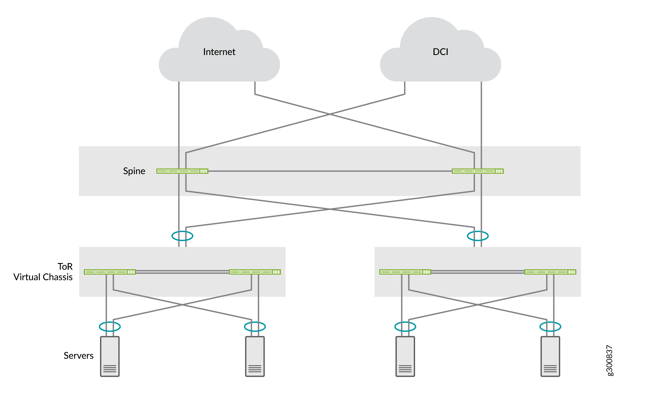
This NCE shows how to deploy a collapsed spine architecture for two data centers that each have two QFX5120 spine switches and two Layer 2 ToR switches deployed as a Virtual Chassis. The data centers are connected to each other through the spine devices with Layer 3 Data Center Interconnect (DCI). Use EVPN multihoming to multihome the ToR switches to the spine devices. The the servers are multihomed to the ToR switches. Figure 1 shows the completed collapsed spine architecture.
For multicast support, we deliver:
-
Layer 3 multicast in a QFX5120 collapsed-spine design using EVPN OISM with symmetric bridge domains.
-
Layer 2 multicast IGMPv2 snooping in EVPN-VXLAN using:
-
EVPN Selective Multicast Ethernet Tag (SMET) Type 6 routes
-
EVPN Join and Leave Sync (Type 7 and Type 8) routes when a multicast receiver is multihomed at Layer 2 to the collapsed spine devices using an ESI-LAG.
-
Understanding Collapsed Spine Architecture
In a collapsed spine architecture, the spine devices act as both spine and leaf devices. Because the ToRs are Layer 2 only and do not support VXLAN, they do not act as leaf devices. Normal leaf device activity is handled, or collapsed, onto the spine devices, which means that VXLAN is required only on the spine devices. The collapsed spine operates as a Layer 3 gateway and handles traffic between the VXLANs using IRB interfaces.
Understanding EVPN Multihoming
In a legacy data center with a collapsed spine architecture, the ToR switches need to be connected to the spine switches with multichassis link aggregation groups (MC-LAGs) to improve network resiliency. MC-LAG provides node-level redundancy and link-level redundancy. Traditionally, spine switches in these data centers use Inter-Chassis Control Protocol (ICCP) to provide MC-LAG functionality. However, MC-LAG with ICCP:
Is a proprietary technology.
Cannot efficiently stretch Layer 2 between data centers.
Does not support more than two spine switches.
EVPN provides a standards-based multihoming solution that scales horizontally across two or more spine switches for additional resiliency and bandwidth in case of a spine failure. EVPN multihoming, also known as ESI-LAG, provides MC-LAG functionality for the Layer 2 ToR switches and the servers in this architecture without the drawbacks of ICCP-based MC-LAG.
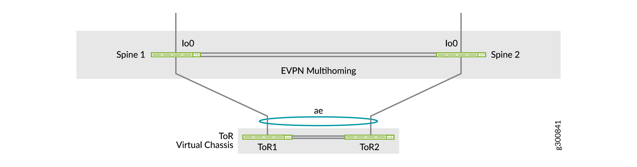
A collapsed spine architecture where the ToR switches are multihomed to the spines is a data center architecture that supports legacy ToR switches when they do not support EVPN-VXLAN. Figure 2 shows a collapsed spine architecture with two spine switches for simplicity and a ToR device implemented as a Virtual Chassis (see Understanding Virtual Chassis).
See Also
Understanding VXLAN
Network overlays are created by encapsulating traffic and tunneling it over a physical network. The VXLAN tunneling protocol encapsulates Layer 2 Ethernet frames in Layer 3 UDP packets. VXLAN enables virtual Layer 2 subnets or segments that can span the underlying physical Layer 3 network.
In a VXLAN overlay network, each Layer 2 subnet or segment is uniquely identified by a virtual network identifier (VNI). A VNI segments traffic the same way that a VLAN ID segments traffic. As is the case with VLANs, endpoints within the same virtual network can communicate directly with each other. Endpoints in different virtual networks require a device that supports inter-VNI routing.
The entity that performs VXLAN encapsulation and decapsulation is called a VXLAN tunnel endpoint (VTEP). Each VTEP is typically assigned a unique IP address.
Understanding EVPN
EVPN is one of the extensions to BGP that allows the network to carry network layer reachability information (NLRI) such as Layer 2 MAC addresses and Layer 3 IP addresses. This control plane technology uses MP-BGP for MAC and IP address endpoint distribution, where MAC addresses are treated as routes. EVPN enables devices acting as VTEPs to exchange reachability information with each other about their endpoints.
EVPN provides multipath forwarding and redundancy through an all-active model. The access layer can connect to two or more spine devices and forward traffic using all of the links. If an access link or spine device fails, traffic flows from the access layer toward the spine layer using the remaining active links. For traffic in the other direction, remote spine devices update their forwarding tables to send traffic to the remaining active spine devices connected to the multihomed Ethernet segment.
Overlay Network
This architecture uses VXLAN as the overlay data plane encapsulation protocol and MP-BGP with EVPN signaling as the overlay control plane protocol.
Data Plane Overlay
This architecture uses VXLAN as the overlay data plane encapsulation protocol on the collapsed spine switches. A switch that functions as a Layer 2 or Layer 3 VXLAN gateway acts as the VXLAN tunnel endpoint and can encapsulate and decapsulate data packets.
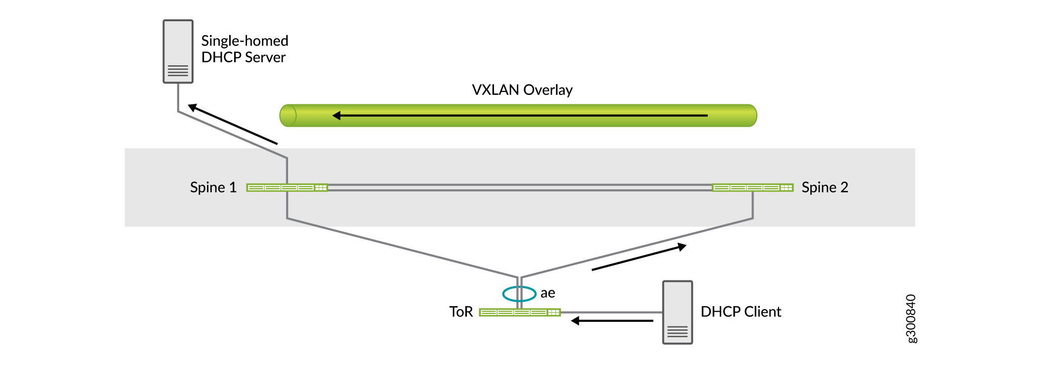
In a single data center deployment with two spine switches, the VXLAN overlay between the spine switches is used for traffic between the two devices. For example, if there is a single-homed server connected to one of the spine devices, the VXLAN overlay carries the traffic to the other spine device either by design or in the case of a link failure.
As shown in the figure below, the DHCP server is single-homed to Spine 1. Traffic from the DHCP client might get sent to Spine 2 because of load sharing. Spine 2 sends the traffic to the DHCP server over the VXLAN overlay with Spine 1.
Control Plane Overlay
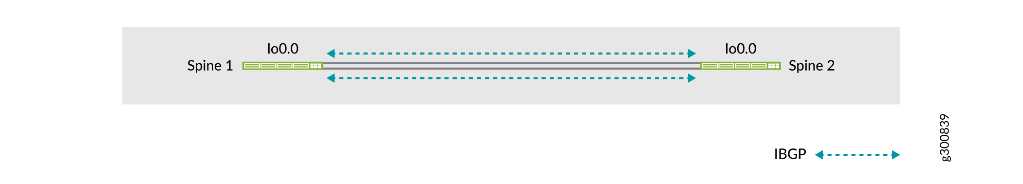
MP-BGP with EVPN signaling acts as the overlay control plane protocol in this example. The spine switches establish IBGP sessions between each other. Figure 4 shows the topology of the overlay network.
See Also
Underlay Network
In smaller data centers there is no super spine layer so the spine switches are directly connected to each other. The spine switches can use a dynamic routing protocol in the underlay. The primary requirement in the underlay network is that all spine devices have loopback reachability. You can use any Layer 3 routing protocol to exchange loopback addresses between the core and spine devices.
In this example, we use EBGP as the underlay routing protocol between the spine switches. EBGP provides benefits like better prefix filtering, traffic engineering, and traffic tagging. Figure 5 shows the topology of the spine underlay network.

Use at least two links between the spine switches. Loss of connectivity between the spine switches could lead to a split-brain state. See Split-Brain State for more information.
Top-of-Rack Switches
Because the ToR switches do not participate in the EVPN-VXLAN fabric and operate at Layer 2 only, you can implement them as a Virtual Chassis. In this example, the ToR switches are deployed as a two-member Virtual Chassis.
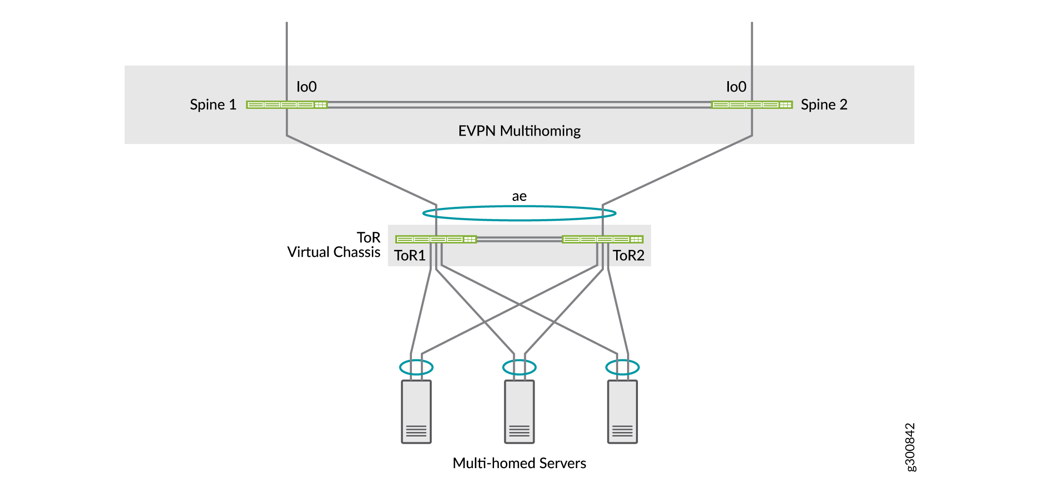
The uplinks from the ToR switches to the spine switches are Layer 2 trunk LAG ports with VLANs relevant to the ToR switch. Each Virtual Chassis is multihomed to two spine switches using EVPN multihoming. Figure 6 shows the topology of a Virtual Chassis as a ToR device that is multihomed to the two spine devices. For redundancy and better resiliency, this figure shows spine to ToR Virtual Chassis connections that link to different Virtual Chassis members, so the Virtual Chassis ToR device is still reachable even if one of the Virtual Chassis members goes down.
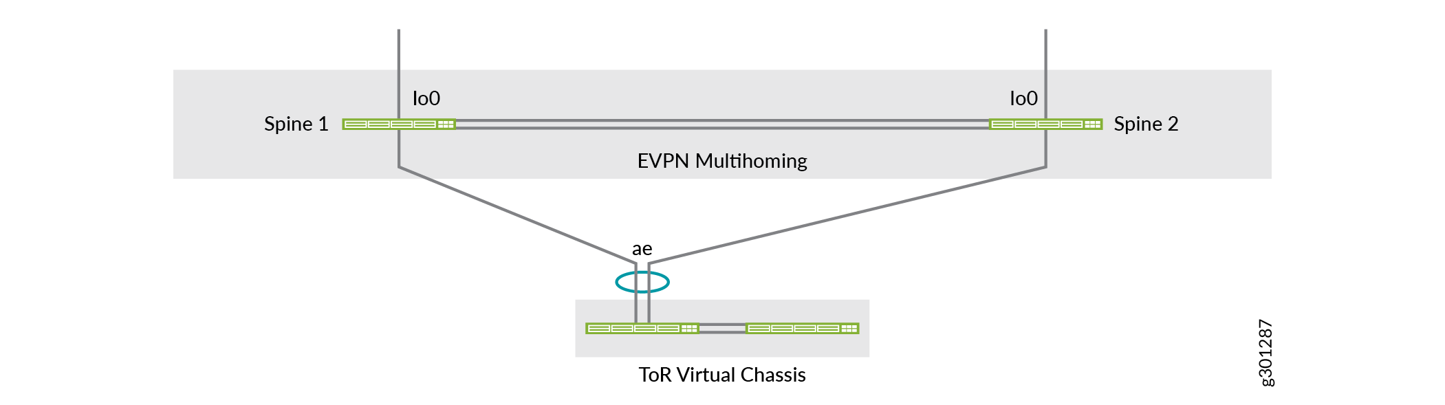
The spine to ToR Virtual Chassis connections in the multihoming aggregated Ethernet links can also include links to the same Virtual Chassis member, which is how this network configuration example is configured. Figure 7 shows a logical view of the multihoming topology that matches the configuration in this document.
Understanding Virtual Chassis
In this example, we implement the ToR switches in a Virtual Chassis. Virtual Chassis can interconnect multiple standalone switches into one logical device and manage the logical device as a single chassis. Use Virtual Chassis for the ToR switches to:
Manage multiple devices as a single device with the same or similar capabilities as the standalone device.
Increase fault tolerance and high availability.
Flatten your network and reduce networking overhead by allowing network devices to synchronize to one resilient logical device.
Enable a simplified Layer 2 network topology that minimizes or eliminates the need for loop prevention protocols such as Spanning Tree Protocol (STP).
Provide redundancy and load sharing for servers that are multihomed across the Virtual Chassis members.
Virtual Chassis provides a single control plane and distributed data plane for simplified management at the ToR layer. The ToR switches behave like line cards on a single chassis. Because the Virtual Chassis behaves like a single chassis, servers connected to the Virtual Chassis might experience downtime during software upgrades of the ToR switches.
See Also
Servers
The data center servers in this example are multihomed to the ToR switches that are deployed as a Virtual Chassis. Server connectivity can be distributed across the two ToR switches with LAG.
SRX Chassis Cluster
In this example, we are deploying SRX security devices in a chassis cluster that is connected to the spine devices to provide advanced security. In a chassis cluster, two SRX Series Firewalls operate as a single device to provide device, interface, and service-level redundancy. Configuration files and the dynamic runtime session states are synchronized between SRX Series Firewalls in a chassis cluster. Use an SRX chassis cluster to:
Prevent single device failure that results in a loss of connectivity.
Provide high availability between security devices when connecting branch and remote site links to larger corporate offices.
Ensure connectivity in the event of a device or link failure.