How to Configure a Collapsed Spine with EVPN Multihoming
Requirements
This example assumes that you have two data centers (DC1 and DC2) with separate networks. This example uses the following devices and software:
DC1:
Two spine switches: QFX5120-48Y running Junos OS Release 18.4R2-S1.4
Two ToR switches: EX4300-48T running Junos OS Release 18.1R3-S6.1
Two security devices: SRX345 devices running Junos OS Release 18.2R3.4 (Optional add-on configuration)
Four servers
DC2:
Two spine switches: QFX5120-48Y running Junos OS Release 18.4R2-S1.4
Two ToR switches: EX4300-48T running Junos OS Release 18.1R3-S6.1
Two servers
Each pair of ToR switches should already be configured as a Virtual Chassis. See Understanding EX Series Virtual Chassis for more information about forming a Virtual Chassis with EX4300 switches. This example configuration uses multihoming aggregated Ethernet links between the ToR Virtual Chassis and the two spine devices on only one member in the Virtual Chassis. If possible, for better resiliency, you can connect the multihoming aggregated Ethernet links between the Virtual Chassis and the spine devices using interfaces from different Virtual Chassis members.
Overview
Use this example to configure a collapsed spine architecture with EVPN multihoming of the ToR switches. We have two data centers with an optional Data Center Interconnect (DCI) configuration, an optional SRX cluster for added security, and an optional DHCP relay configuration. This configuration example shows you how to configure this architecture in DC1. You can use a similar configuration in DC2.
Topology
In this deployment, there are two data centers: DC1 and DC2. The data center networks are configured with a collapsed spine architecture using QFX5120 as the spine switches. In this case, we recommend that you limit the EVPN-VXLAN fabric to the local data center.
You can optionally connect the data centers using Layer 3 DCI in the underlay. This use case does not require Layer 2 stretch between the data centers. Inter-data center traffic is Layer 3 only and is routed through the SRX cluster in DC1 for advanced inspection.
Figure 1 shows the logical connectivity between the components used in this NCE.
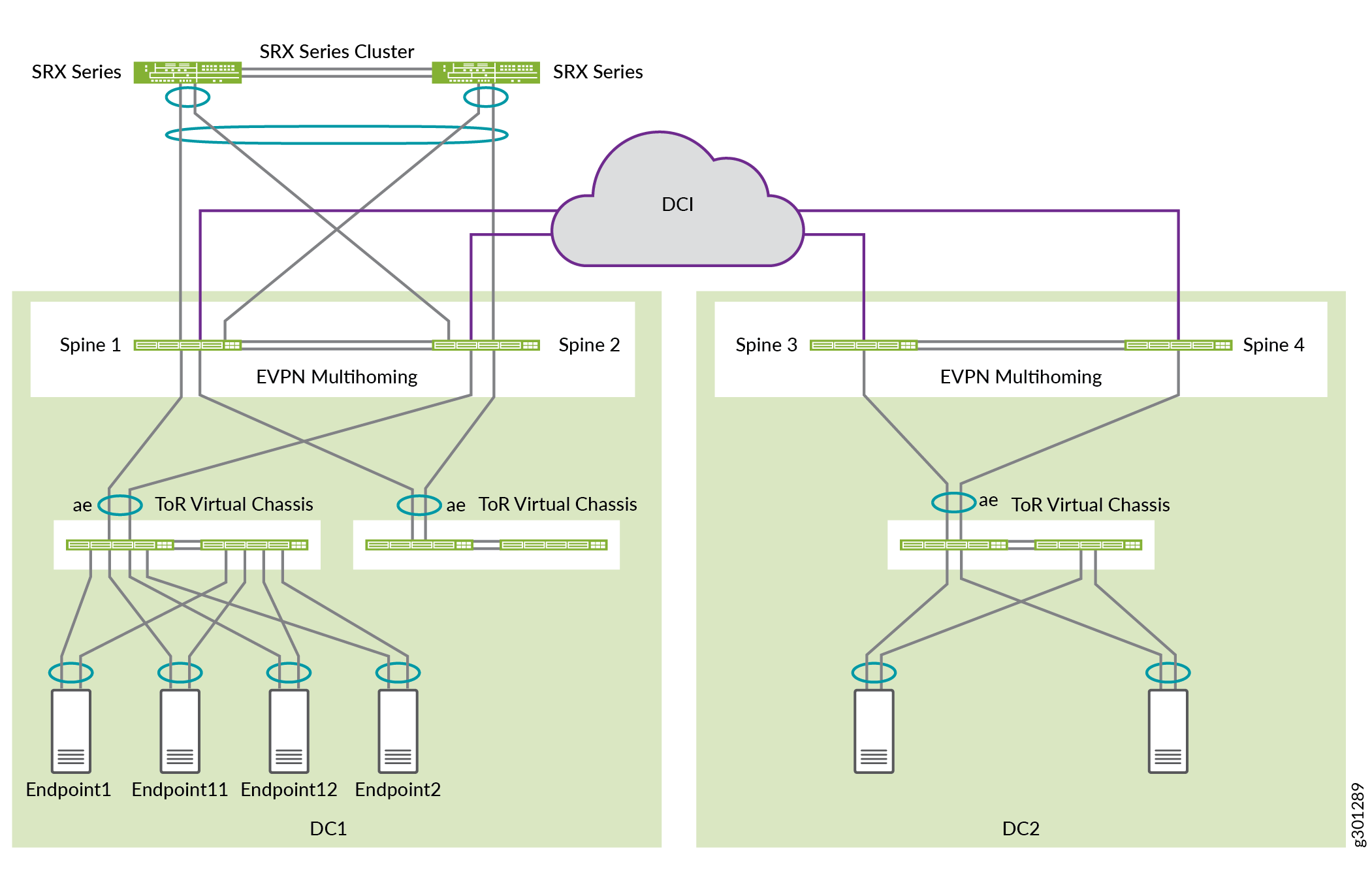
There are two tenants in DC1: JNPR1 and JNPR2. Any inter-tenant traffic between JNPR1 and JNPR2 in DC1 is routed through the SRX firewall cluster for security.
DC1:
VLANs 201 and 202 belong to JNPR1.
VLANs 211 and 212 belong to JNPR2.
DC1 has servers in VLANs 201, 202, 211, and 212.
DC2:
VLANs 221 and 222 belong to the default tenant, which is the same as the default routing instance.
DC2 has servers in VLANs 221 and 222.
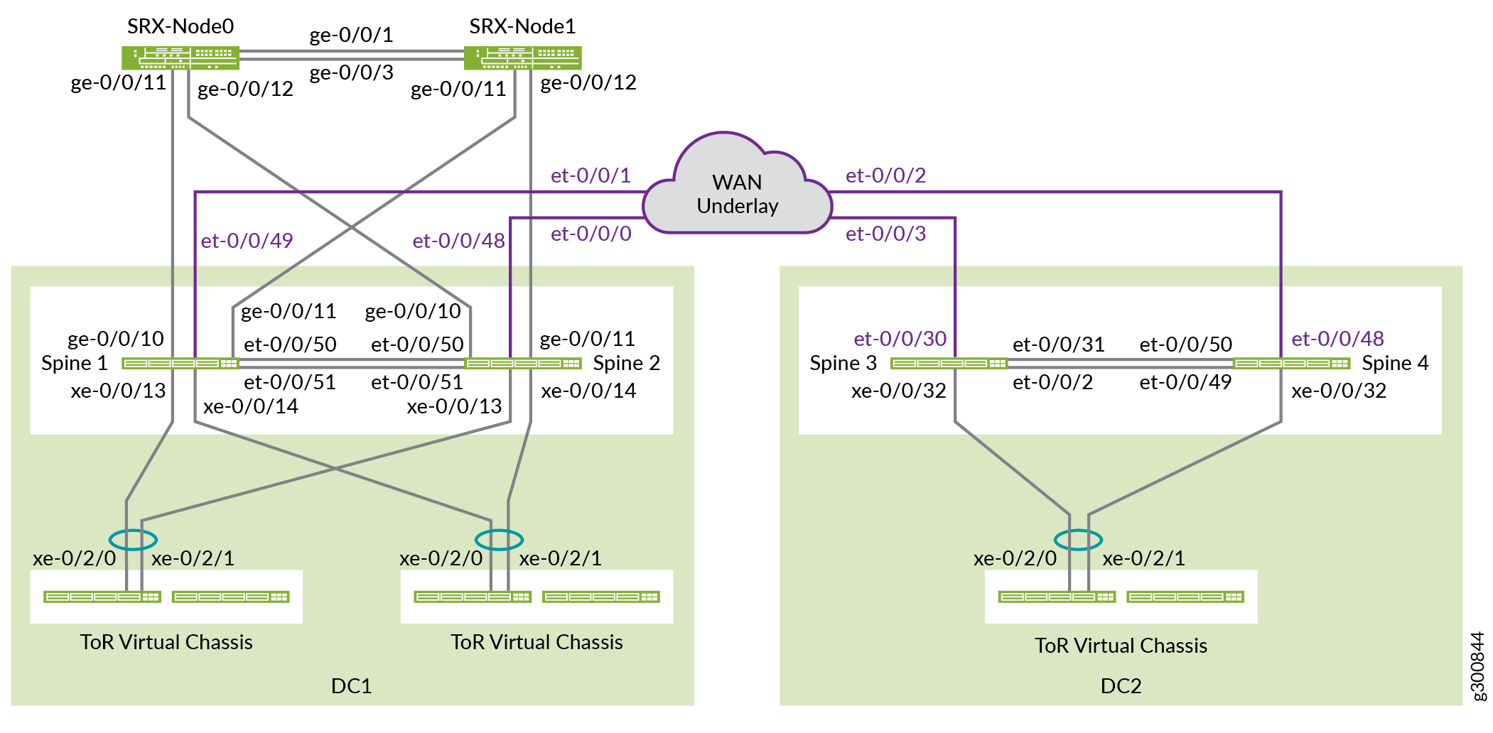
Figure 2 shows the physical connectivity between the components used in this NCE.
Before You Begin
You need to implement some basic configuration on your devices before you configure the fabric.
Procedure
Step-by-Step Procedure
By default, no aggregated Ethernet interfaces are created. You must set the number of aggregated Ethernet interfaces before you can configure them. Once you set the device count, the system creates that number of empty aggregated Ethernet interfaces, each with a globally unique MAC address. You can create more aggregated Ethernet interfaces by increasing the device count to the number of ESI-LAG interfaces required on the device.
Set the number of aggregated Ethernet interfaces on all spine switches and ToR switches.
set chassis aggregated-devices ethernet device-count 15
Ports 0 to 47 on a QFX5120-48Y operate as 10-gigabit ports by default. The SRX devices support only 1 gigabit. Configure the ports on Spine 1 and Spine 2 that are connected to the SRX Series Firewall to be 1-gigabit ports. In this case, these ports are ge-0/0/10 and ge-0/0/11. To enable 1 gigabit on these ports, configure the speed of the first port in the quad, which in this case is ge-0/0/8.
Use the following statement on Spine 1 and Spine 2:
set chassis fpc 0 pic 0 port 8 speed 1G
Note:You can configure the 1-gigabit and 25-gigabit port speeds only per quad (group of four ports) and not individually. All ports operate at a single speed within the quad. For instance, if you configure ports 8 through 11 to operate as 1-gigabit Ethernet ports and you insert a 10-gigabit SFP+ transceiver in port 10, an interface is not created for this port.
Auto speed detection mode detects 100-gigabit Ethernet interfaces and 40-gigabit Ethernet interfaces and automatically channelizes them. Automatic channelization and speed detection are enabled by default. In this example, auto channelization would divide each 40-gigabit Ethernet interface into four 10-gigabit Ethernet interfaces.
Disable auto channelization on ports et-0/0/2 and et-0/0/31 on Spine 3 and ports et-0/0/49 and et-0/0/50 on Spine 4 so that they remain 40-gigabit Ethernet interfaces.
Spine 3:
set chassis fpc 0 pic 0 port 2 channel-speed disable-auto-speed-detection
set chassis fpc 0 pic 0 port 31 channel-speed disable-auto-speed-detection
Spine 4:
set chassis fpc 0 pic 0 port 49 channel-speed disable-auto-speed-detection
set chassis fpc 0 pic 0 port 50 channel-speed disable-auto-speed-detection
Configure the Underlay
In this topology, the IP fabric is only between the two spine switches, as shown in Figure 3. The two spine switches establish EBGP peering over the point-to-point links to exchange loopback addresses with each other.

Configure Spine 1
Step-by-Step Procedure
Configure the interfaces on Spine 1.
set interfaces et-0/0/50 description "* connected to DC1-Spine2"
set interfaces et-0/0/50 traps
set interfaces et-0/0/50 mtu 9216
set interfaces et-0/0/50 unit 0 family inet address 192.168.100.5/31
set interfaces et-0/0/51 description "* connected to DC1-Spine2"
set interfaces et-0/0/51 traps
set interfaces et-0/0/51 mtu 9216
set interfaces et-0/0/51 unit 0 family inet address 192.168.100.7/31
set interfaces lo0 unit 0 description "** DC1 Spine1 Loopback"
set interfaces lo0 unit 0 family inet address 192.168.255.13/32
Configure the EBGP underlay.
set protocols bgp log-updown
set protocols bgp graceful-restart restart-time 30
set protocols bgp group UNDERLAY type external
set protocols bgp group UNDERLAY description "Connection to EBGP UNDERLAY"
set protocols bgp group UNDERLAY import UNDERLAY-IMPORT
set protocols bgp group UNDERLAY family inet unicast
set protocols bgp group UNDERLAY authentication-key "$ABC123"
set protocols bgp group UNDERLAY export UNDERLAY-EXPORT
set protocols bgp group UNDERLAY local-as 65013
set protocols bgp group UNDERLAY multipath multiple-as
set protocols bgp group UNDERLAY neighbor 192.168.100.4 peer-as 65012
set protocols bgp group UNDERLAY neighbor 192.168.100.6 peer-as 65012
Configure the import and export policies.
set policy-options policy-statement UNDERLAY-EXPORT term LOOPBACK from route-filter 192.168.255.0/24 orlonger
set policy-options policy-statement UNDERLAY-EXPORT term LOOPBACK then accept
set policy-options policy-statement UNDERLAY-EXPORT term DEFAULT then reject
set policy-options policy-statement UNDERLAY-IMPORT term LOOPBACK from route-filter 192.168.255.0/24 orlonger
set policy-options policy-statement UNDERLAY-IMPORT term LOOPBACK then accept
set policy-options policy-statement UNDERLAY-IMPORT term DEFAULT then reject
Enable ECMP and ECMP fast reroute protection. Enable per-flow load balancing, which you do with the
per-packetkeyword.set policy-options policy-statement ECMP-POLICY then load-balance per-packet set routing-options forwarding-table export ECMP-POLICY
If a link goes down, ECMP uses fast reroute protection to shift packet forwarding to operational links, which decreases packet loss. Fast reroute protection updates ECMP sets for the interface without having to wait for the route table to update. When the next route table update occurs, a new ECMP set can be added with fewer links, or the route can point to a single next hop.
set routing-options forwarding-table ecmp-fast-reroute
By default, the ARP aging timer is set at 20 minutes and the MAC aging timer is set at 5 minutes. To avoid synchronization issues with MAC and MAC-IP binding entries in an EVPN-VXLAN environment, configure ARP aging to be faster than MAC aging.
set system arp aging-timer 5 set protocols l2-learning global-mac-ip-table-aging-time 300 set protocols l2-learning global-mac-table-aging-time 600
Configure Spine 2
Step-by-Step Procedure
Repeat the configuration from Spine 1 on Spine 2.
Configure the interfaces on Spine 2.
set interfaces et-0/0/50 description "* connected to DC1-Spine1" set interfaces et-0/0/50 traps set interfaces et-0/0/50 mtu 9216 set interfaces et-0/0/50 unit 0 family inet address 192.168.100.4/31 set interfaces et-0/0/51 description "* connected to DC1-Spine1" set interfaces et-0/0/51 traps set interfaces et-0/0/51 mtu 9216 set interfaces et-0/0/51 unit 0 family inet address 192.168.100.6/31 set interfaces lo0 unit 0 description "** DC1 Spine2 Loopback" set interfaces lo0 unit 0 family inet address 192.168.255.12/32
Configure the EBGP underlay.
set protocols bgp log-updown set protocols bgp graceful-restart restart-time 30 set protocols bgp group UNDERLAY type external set protocols bgp group UNDERLAY description "EBGP UNDERLAY" set protocols bgp group UNDERLAY import UNDERLAY-IMPORT set protocols bgp group UNDERLAY family inet unicast set protocols bgp group UNDERLAY authentication-key "$ABC123" set protocols bgp group UNDERLAY export UNDERLAY-EXPORT set protocols bgp group UNDERLAY local-as 65012 set protocols bgp group UNDERLAY multipath multiple-as set protocols bgp group UNDERLAY neighbor 192.168.100.5 peer-as 65013 set protocols bgp group UNDERLAY neighbor 192.168.100.7 peer-as 65013
Configure the import and export policies.
set policy-options policy-statement UNDERLAY-EXPORT term LOOPBACK from route-filter 192.168.255.0/24 orlonger set policy-options policy-statement UNDERLAY-EXPORT term LOOPBACK then accept set policy-options policy-statement UNDERLAY-EXPORT term DEFAULT then reject set policy-options policy-statement UNDERLAY-IMPORT term LOOPBACK from route-filter 192.168.255.0/24 orlonger set policy-options policy-statement UNDERLAY-IMPORT term LOOPBACK then accept set policy-options policy-statement UNDERLAY-IMPORT term DEFAULT then reject
Enable ECMP and ECMP fast reroute protection.
set policy-options policy-statement ECMP-POLICY then load-balance per-packet set routing-options forwarding-table export ECMP-POLICY set routing-options forwarding-table ecmp-fast-reroute
To avoid synchronization issues with MAC and MAC-IP binding entries in an EVPN-VXLAN environment, configure ARP aging to be faster than MAC aging.
set system arp aging-timer 5
set protocols l2-learning global-mac-ip-table-aging-time 300
set protocols l2-learning global-mac-table-aging-time 600
Verify the Underlay
Step-by-Step Procedure
Verify that both BGP neighbor sessions are established on Spine 1.
user@spine1> show bgp neighbor 192.168.100.4 Peer: 192.168.100.4+179 AS 65012 Local: 192.168.100.5+51424 AS 65013 Description: Connection to EBGP UNDERLAY Group: UNDERLAY Routing-Instance: master Forwarding routing-instance: master Type: External State: Established Flags: <Sync> Last State: OpenConfirm Last Event: RecvKeepAlive Last Error: Cease Export: [ UNDERLAY-EXPORT ] Import: [ UNDERLAY-IMPORT ] . . .
user@spine1> show bgp neighbor 192.168.100.6 Peer: 192.168.100.6+59705 AS 65012 Local: 192.168.100.7+179 AS 65013 Description: Connection to EBGP UNDERLAY Group: UNDERLAY Routing-Instance: master Forwarding routing-instance: master Type: External State: Established Flags: <Sync> Last State: OpenConfirm Last Event: RecvKeepAlive Last Error: Cease Export: [ UNDERLAY-EXPORT ] Import: [ UNDERLAY-IMPORT ] . . .
Verify that the loopback address of Spine 2 (192.168.255.12) is received by Spine 1 from both BGP neighbor sessions.
user@spine1> show route receive-protocol bgp 192.168.100.4 inet.0: 17 destinations, 25 routes (17 active, 0 holddown, 0 hidden) Restart Complete Prefix Nexthop MED Lclpref AS path * 192.168.255.12/32 192.168.100.4 65012 I . . .
user@spine1> show route receive-protocol bgp 192.168.100.6 inet.0: 17 destinations, 25 routes (17 active, 0 holddown, 0 hidden) Restart Complete Prefix Nexthop MED Lclpref AS path 192.168.255.12/32 192.168.100.6 65012 I
user@spine1> show route 192.168.255.12 inet.0: 17 destinations, 25 routes (17 active, 0 holddown, 0 hidden) Restart Complete + = Active Route, - = Last Active, * = Both 192.168.255.12/32 *[BGP/170] 00:39:43, localpref 100, from 192.168.100.4 AS path: 65012 I, validation-state: unverified to 192.168.100.4 via et-0/0/50.0 > to 192.168.100.6 via et-0/0/51.0 [BGP/170] 00:39:43, localpref 100 AS path: 65012 I, validation-state: unverified > to 192.168.100.6 via et-0/0/51.0Ping the loopback of the other spine device from Spine 1.
user@spine1> ping 192.168.255.12 source 192.168.255.13 PING 192.168.255.12 (192.168.255.12): 56 data bytes 64 bytes from 192.168.255.12: icmp_seq=0 ttl=64 time=0.746 ms 64 bytes from 192.168.255.12: icmp_seq=1 ttl=64 time=0.699 ms 64 bytes from 192.168.255.12: icmp_seq=2 ttl=64 time=0.784 ms
Configure the Overlay
This section shows how to configure the overlay. It includes IBGP peerings and the VLAN to VXLAN mappings for the virtual networks.
Configure Spine 1
Step-by-Step Procedure
Configure IBGP peering between the Spine 1 and Spine 2 loopback addresses.
set protocols bgp group EVPN_FABRIC type internal set protocols bgp group EVPN_FABRIC local-address 192.168.255.13 set protocols bgp group EVPN_FABRIC family evpn signaling set protocols bgp group EVPN_FABRIC authentication-key "$ABC123" set protocols bgp group EVPN_FABRIC local-as 65100 set protocols bgp group EVPN_FABRIC multipath set protocols bgp group EVPN_FABRIC bfd-liveness-detection minimum-interval 1000 set protocols bgp group EVPN_FABRIC bfd-liveness-detection multiplier 3 set protocols bgp group EVPN_FABRIC neighbor 192.168.255.12 set protocols bgp group EVPN_FABRIC vpn-apply-export
Configure the VLANs and VLAN to VXLAN mapping.
set vlans VLAN-201 description "jnpr_1 - bridge domain id 201" set vlans VLAN-201 vlan-id 201 set vlans VLAN-201 vxlan vni 5201 set vlans VLAN-202 description "jnpr_1 - bridge domain id 202" set vlans VLAN-202 vlan-id 202 set vlans VLAN-202 vxlan vni 5202 set vlans VLAN-211 description "jnpr_2 - bridge domain id 211" set vlans VLAN-211 vlan-id 211 set vlans VLAN-211 vxlan vni 5211 set vlans VLAN-212 description "jnpr_2 - bridge domain id 212" set vlans VLAN-212 vlan-id 212 set vlans VLAN-212 vxlan vni 5212
Configure the following switch options:
The virtual tunnel endpoint (VTEP) source interface. This is the loopback address on Spine 1.
The route distinguisher for routes generated by this device.
The route target.
set switch-options vtep-source-interface lo0.0 set switch-options route-distinguisher 192.168.255.13:1 set switch-options vrf-target target:1:999 set switch-options vrf-target auto
The route target configured under
vrf-targetis used by Type 1 EVPN routes. Type 2 and Type 3 EVPN routes use the auto-derived per-VNI route target for export and import.Configure the EVPN protocol. First, configure VXLAN as the data plane encapsulation for EVPN.
set protocols evpn encapsulation vxlan
Next, configure the VNIs that are part of this EVPN-VXLAN MP-BGP domain. Use
set protocols evpn extended-vni-list allto configure all VNIs, or configure each VNI separately as shown below.set protocols evpn extended-vni-list 5201 set protocols evpn extended-vni-list 5202 set protocols evpn extended-vni-list 5211 set protocols evpn extended-vni-list 5212
If the data center has only two spine switches that have only BGP neighbor sessions with each other, you must disable core isolation on both spine switches. Otherwise, if a spine switch goes down, the other spine switch loses all BGP neighbor sessions, which places the ToR-facing ports into LACP standby mode and results in complete traffic loss. See Split-Brain State and Understanding When to Disable EVPN-VXLAN Core Isolation for more information.
set protocols evpn no-core-isolation
Configure Spine 2
Step-by-Step Procedure
To avoid synchronization issues with MAC and MAC-IP binding entries in an EVPN-VXLAN environment, configure ARP aging to be faster than MAC aging.
set system arp aging-timer 5
set protocols l2-learning global-mac-ip-table-aging-time 300
set protocols l2-learning global-mac-table-aging-time 600
Configure IBGP peering.
set protocols bgp group EVPN_FABRIC type internal set protocols bgp group EVPN_FABRIC local-address 192.168.255.12 set protocols bgp group EVPN_FABRIC family evpn signaling set protocols bgp group EVPN_FABRIC authentication-key "$ABC123" set protocols bgp group EVPN_FABRIC local-as 65100 set protocols bgp group EVPN_FABRIC multipath set protocols bgp group EVPN_FABRIC bfd-liveness-detection minimum-interval 1000 set protocols bgp group EVPN_FABRIC bfd-liveness-detection multiplier 3 set protocols bgp group EVPN_FABRIC neighbor 192.168.255.13 set protocols bgp group EVPN_FABRIC vpn-apply-export
Configure the VLANs and VLAN to VXLAN mapping.
set vlans VLAN-201 description "jnpr_1 - bridge domain id 201"
set vlans VLAN-201 vlan-id 201
set vlans VLAN-201 vxlan vni 5201

set vlans VLAN-202 description "jnpr_1 - bridge domain id 202"
set vlans VLAN-202 vlan-id 202
set vlans VLAN-202 vxlan vni 5202

set vlans VLAN-211 description "jnpr_2 - bridge domain id 211"
set vlans VLAN-211 vlan-id 211
set vlans VLAN-211 vxlan vni 5211

set vlans VLAN-212 description "jnpr_2 - bridge domain id 212"
set vlans VLAN-212 vlan-id 212
set vlans VLAN-212 vxlan vni 5212
Configure the following switch options.
set switch-options vtep-source-interface lo0.0
set switch-options route-distinguisher 192.168.255.12:1
set switch-options vrf-target target:1:999
set switch-options vrf-target auto
Configure the EVPN protocol.
set protocols evpn encapsulation vxlan
Next, configure the VNIs that are part of this EVPN-VXLAN MP-BGP domain. Use
set protocols evpn extended-vni-list allto configure all VNIs, or configure each VNI separately as shown below.set protocols evpn extended-vni-list 5201 set protocols evpn extended-vni-list 5202 set protocols evpn extended-vni-list 5211 set protocols evpn extended-vni-list 5212
If the data center has only two spine switches that only have BGP neighbor sessions with each other, you must disable core isolation on both spine switches.
set protocols evpn no-core-isolation
Verify the Overlay
Step-by-Step Procedure
Verify the IBGP peering between Spine 1 and Spine 2 is established.
user@spine1> show bgp neighbor 192.168.255.12
Peer: 192.168.255.12+179 AS 65100 Local: 192.168.255.13+62666 AS 65100
  Description: Overlay neighbor with peer
  Group: EVPN_FABRIC           Routing-Instance: master
  Forwarding routing-instance: master
  Type: Internal    State: Established    Flags:<Sync>
  Last State: OpenConfirm   Last Event: RecvKeepAlive
  Last Error: Hold Timer Expired Error
  Options: <Preference LocalAddress HoldTime AuthKey GracefulRestart LogUpDown AddressFamily Multipath LocalAS Rib-group Refresh>
  Authentication key is configured
  Address families configured: evpn
Verify the source VTEP for the EVPN domain.
user@spine1> show ethernet-switching vxlan-tunnel-end-point source
Logical System Name       Id  SVTEP-IP         IFL   L3-Idx    SVTEP-Mode
    <default>                 0   192.168.255.13   lo0.0    0
    L2-RTT                   Bridge Domain              VNID     MC-Group-IP
    default-switch           VLAN-201+201               5201     0.0.0.0
    default-switch           VLAN-202+202               5202     0.0.0.0
    default-switch           VLAN-211+211               5211     0.0.0.0
    default-switch           VLAN-212+212               5212     0.0.0.0
Verify all the source VTEP and remote VTEPs.
user@spine1> show interfaces vtep
Physical interface: vtep, Enabled, Physical link is Up
  Interface index: 641, SNMP ifIndex: 506
  Type: Software-Pseudo, Link-level type: VxLAN-Tunnel-Endpoint, MTU: Unlimited, Speed: Unlimited
  Device flags   : Present Running
  Link type      : Full-Duplex
  Link flags     : None
  Last flapped   : Never
    Input packets : 0
    Output packets: 0

  Logical interface vtep.32768 (Index 545) (SNMP ifIndex 548)
    Flags: Up SNMP-Traps 0x4000 Encapsulation: ENET2
    VXLAN Endpoint Type: Source, VXLAN Endpoint Address: 192.168.255.13, L2 Routing Instance: default-switch, L3 Routing Instance: default
    Input packets : 0
    Output packets: 0

  Logical interface vtep.32769 (Index 560) (SNMP ifIndex 550)
    Flags: Up SNMP-Traps Encapsulation: ENET2
    VXLAN Endpoint Type: Remote, VXLAN Endpoint Address: 192.168.255.12, L2 Routing Instance: default-switch, L3 Routing Instance: default
    Input packets : 9140
    Output packets: 0
    Protocol eth-switch, MTU: Unlimited
      Flags: Trunk-Mode
Configure and Segment Layer 3
Configure Spine 1
Step-by-Step Procedure
Configure routing and forwarding options.
Note:Changing routing and forwarding options like
next-hop,overlay-ecmp, orchained-composite-next-hopcauses the Packet Forwarding Engine to restart, which interrupts all forwarding operations.Set the number of next hops to at least the expected number of ARP entries in the overlay. See next-hop (VXLAN Routing) for more information about configuring
vxlan-routing next-hop.Enable two-level equal-cost multipath next hops using the
overlay-ecmpstatement. This statement is required for a Layer 3 EVPN-VXLAN overlay network when pure Type 5 routing is also configured. We strongly recommend that you configure this statement when pure Type 5 routes are enabled.The
chained-composite-next-hopconfiguration is a must for EVPN pure Type 5 with VXLAN encapsulation. Without this, the PFE will not configure the tunnel next hop.Configure the router ID to be the same as the loopback IP address used as the VTEP source and the overlay BGP local address.
set forwarding-options vxlan-routing next-hop 32768
set forwarding-options vxlan-routing overlay-ecmp
set routing-options forwarding-table chained-composite-next-hop ingress evpn
set routing-options router-id 192.168.255.13
To enable the default gateway function, configure IRB interfaces each with a unique IP address and a virtual gateway address (VGA), which must be an anycast IP address. When you specify an IPv4 address for the VGA, the Layer 3 VXLAN gateway automatically generates 00:00:5e:00:01:01 as the MAC address. This example shows you how to manually configure the virtual gateway MAC address. Configure the same virtual gateway MAC address on both spine devices for a given IRB.
Note:If the VGA IP address is lower than the IRB IP address, you must use the
preferredoption in the IRB configuration as shown in this example.set interfaces irb unit 201 virtual-gateway-accept-data set interfaces irb unit 201 description "** L3 interface for VLAN-201 in jnpr_1" set interfaces irb unit 201 family inet address 192.168.201.3/24 virtual-gateway-address 192.168.201.1 set interfaces irb unit 201 family inet address 192.168.201.3/24 preferred set interfaces irb unit 201 virtual-gateway-v4-mac 3c:8c:93:2e:20:01 set vlans VLAN-201 l3-interface irb.201 set interfaces irb unit 202 virtual-gateway-accept-data set interfaces irb unit 202 description "** L3 interface for VLAN-202 in jnpr_1" set interfaces irb unit 202 family inet address 192.168.202.3/24 virtual-gateway-address 192.168.202.1 set interfaces irb unit 202 family inet address 192.168.202.3/24 preferred set interfaces irb unit 202 virtual-gateway-v4-mac 3c:8c:93:2e:20:02 set vlans VLAN-202 l3-interface irb.202 set interfaces irb unit 211 virtual-gateway-accept-data set interfaces irb unit 211 description "** L3 interface for VLAN-211 in jnpr_2" set interfaces irb unit 211 family inet address 192.168.211.3/24 virtual-gateway-address 192.168.211.1 set interfaces irb unit 211 family inet address 192.168.211.3/24 preferred set interfaces irb unit 211 virtual-gateway-v4-mac 3c:8c:93:2e:21:11 set vlans VLAN-211 l3-interface irb.211 set interfaces irb unit 212 virtual-gateway-accept-data set interfaces irb unit 212 description "** L3 interface for VLAN-212 in jnpr_2" set interfaces irb unit 212 family inet address 192.168.212.3/24 virtual-gateway-address 192.168.212.1 set interfaces irb unit 212 family inet address 192.168.212.3/24 preferred set interfaces irb unit 212 virtual-gateway-v4-mac 3c:8c:93:2e:21:12 set vlans VLAN-212 l3-interface irb.212
You will configure the same anycast IRB IP and MAC addresses on the IRB interfaces of each spine device. Because the spine devices act as both the spine and leaf devices in a collapsed spine architecture, they are the only devices that need to know about the IRB interfaces. Disable the advertisement of the IRB interfaces to the other devices.
set protocols evpn default-gateway do-not-advertise
Place the IRBs belonging to the different tenants into their respective routing instances. This allows the IRBs in the same routing instances to share a routing table. As a result, the IRBs in a routing instance can route to each other. IRBs in different routing instances can communicate with each other either through an external security policy enforcer like SRX firewalls or if we explicitly leak routes between the routing instances.
set routing-instances JNPR_1_VRF description "VRF for tenant jnpr_1"
set routing-instances JNPR_1_VRF instance-type vrf
set routing-instances JNPR_1_VRF interface irb.201
set routing-instances JNPR_1_VRF interface irb.202
set routing-instances JNPR_1_VRF vrf-table-label
set routing-instances JNPR_1_VRF routing-options multipath


set routing-instances JNPR_2_VRF description "VRF for tenant jnpr_2"
set routing-instances JNPR_2_VRF instance-type vrf
set routing-instances JNPR_2_VRF interface irb.211
set routing-instances JNPR_2_VRF interface irb.212
set routing-instances JNPR_2_VRF vrf-table-label
set routing-instances JNPR_2_VRF routing-options multipath
Configure Type 5 VNI for the routing instances. When setting up a routing instance for EVPN-VXLAN, you must include a loopback interface and its IP address. If you omit the loopback interface and associated IP address, EVPN control packets cannot be processed.
set routing-instances JNPR_1_VRF protocols evpn ip-prefix-routes advertise direct-nexthop
	set routing-instances JNPR_1_VRF protocols evpn ip-prefix-routes encapsulation vxlan
set routing-instances JNPR_1_VRF protocols evpn ip-prefix-routes vni 1101
set routing-instances JNPR_1_VRF protocols evpn ip-prefix-routes export T5_EXPORT

set routing-instances JNPR_2_VRF protocols evpn ip-prefix-routes advertise direct-nexthop
set routing-instances JNPR_2_VRF protocols evpn ip-prefix-routes encapsulation vxlan
set routing-instances JNPR_2_VRF protocols evpn ip-prefix-routes vni 1102
set routing-instances JNPR_2_VRF protocols evpn ip-prefix-routes export T5_EXPORT

set interfaces lo0 unit 1 description "Tenant 1 T5 Loopback"
set interfaces lo0 unit 1 family inet address 192.168.255.21/32
set routing-instances JNPR_1_VRF interface lo0.1

set interfaces lo0 unit 2 description "Tenant 2 T5 Loopback"
set interfaces lo0 unit 2 family inet address 192.168.255.22/32
set routing-instances JNPR_2_VRF interface lo0.2

set policy-options policy-statement T5_EXPORT term 1 from protocol direct
set policy-options policy-statement T5_EXPORT term 1 then accept
set policy-options policy-statement T5_EXPORT term 2 from protocol bgp
set policy-options policy-statement T5_EXPORT term 2 then accept
Configure Spine 2
Step-by-Step Procedure
Configure routing and forwarding options.
Note:Changing routing and forwarding options like
next-hop,overlay-ecmp, orchained-composite-next-hopcauses the Packet Forwarding Engine to restart, which interrupts all forwarding operations.set forwarding-options vxlan-routing next-hop 32768 set forwarding-options vxlan-routing overlay-ecmp set routing-options forwarding-table chained-composite-next-hop ingress evpn set routing-options router-id 192.168.255.12
Configure IRB.
set interfaces irb unit 201 virtual-gateway-accept-data
set interfaces irb unit 201 description "** L3 interface for VLAN-201 in jnpr_1"
set interfaces irb unit 201 family inet address 192.168.201.2/24 virtual-gateway-address 192.168.201.1
set interfaces irb unit 201 family inet address 192.168.201.2/24 preferred
set interfaces irb unit 201 virtual-gateway-v4-mac 3c:8c:93:2e:20:01
set vlans VLAN-201 l3-interface irb.201

set interfaces irb unit 202 virtual-gateway-accept-data
set interfaces irb unit 202 description "** L3 interface for VLAN-202 in jnpr_1"
set interfaces irb unit 202 family inet address 192.168.202.2/24 virtual-gateway-address 192.168.202.1
set interfaces irb unit 202 family inet address 192.168.202.2/24 preferred
set interfaces irb unit 202 virtual-gateway-v4-mac 3c:8c:93:2e:20:02
set vlans VLAN-202 l3-interface irb.202

set interfaces irb unit 211 virtual-gateway-accept-data
set interfaces irb unit 211 description "** L3 interface for VLAN-211 in jnpr_2"
set interfaces irb unit 211 family inet address 192.168.211.2/24 virtual-gateway-address 192.168.211.1
set interfaces irb unit 211 family inet address 192.168.211.2/24 preferred
set interfaces irb unit 211 virtual-gateway-v4-mac 3c:8c:93:2e:21:11
set vlans VLAN-211 l3-interface irb.211

set interfaces irb unit 212 virtual-gateway-accept-data
set interfaces irb unit 212 description "** L3 interface for VLAN-212 in jnpr_2"
set interfaces irb unit 212 family inet address 192.168.212.2/24 virtual-gateway-address 192.168.212.1
set interfaces irb unit 212 family inet address 192.168.212.2/24 preferred
set interfaces irb unit 212 virtual-gateway-v4-mac 3c:8c:93:2e:21:12
set vlans VLAN-212 l3-interface irb.212
Since you have configured the same anycast IRB IP and MAC addresses on the IRB interfaces of both spine switches, disable the advertisement of the IRB interfaces to other devices.
set protocols evpn default-gateway do-not-advertise
Place the IRBs belonging to the different tenants into their respective routing instances.
set routing-instances JNPR_1_VRF description "VRF for tenant jnpr_1"
set routing-instances JNPR_1_VRF instance-type vrf
set routing-instances JNPR_1_VRF interface irb.201
set routing-instances JNPR_1_VRF interface irb.202
set routing-instances JNPR_1_VRF vrf-table-label
set routing-instances JNPR_1_VRF routing-options multipath

set routing-instances JNPR_2_VRF description "VRF for tenant jnpr_2"
set routing-instances JNPR_2_VRF instance-type vrf
set routing-instances JNPR_2_VRF interface irb.211
set routing-instances JNPR_2_VRF interface irb.212
set routing-instances JNPR_2_VRF vrf-table-label
set routing-instances JNPR_2_VRF routing-options multipath
Configure Type 5 VNI for the routing instances.
set routing-instances JNPR_1_VRF protocols evpn ip-prefix-routes advertise direct-nexthop
set routing-instances JNPR_1_VRF protocols evpn ip-prefix-routes encapsulation vxlan
set routing-instances JNPR_1_VRF protocols evpn ip-prefix-routes vni 1101
set routing-instances JNPR_1_VRF protocols evpn ip-prefix-routes export T5_EXPORT

set routing-instances JNPR_2_VRF protocols evpn ip-prefix-routes advertise direct-nexthop
set routing-instances JNPR_2_VRF protocols evpn ip-prefix-routes encapsulation vxlan
set routing-instances JNPR_2_VRF protocols evpn ip-prefix-routes vni 1102
set routing-instances JNPR_2_VRF protocols evpn ip-prefix-routes export T5_EXPORT

set interfaces lo0 unit 101 description "Tenant 1 T5 Loopback"
set interfaces lo0 unit 101 family inet address 192.168.255.31/32
set routing-instances JNPR_1_VRF interface lo0.101

set interfaces lo0 unit 102 description "Tenant 2 T5 Loopback"
set interfaces lo0 unit 102 family inet address 192.168.255.32/32
set routing-instances JNPR_2_VRF interface lo0.102

set policy-options policy-statement T5_EXPORT term 1 from protocol direct
set policy-options policy-statement T5_EXPORT term 1 then accept
set policy-options policy-statement T5_EXPORT term 2 from protocol bgp
set policy-options policy-statement T5_EXPORT term 2 then accept
Configure EVPN Multihoming for the ToR Switches
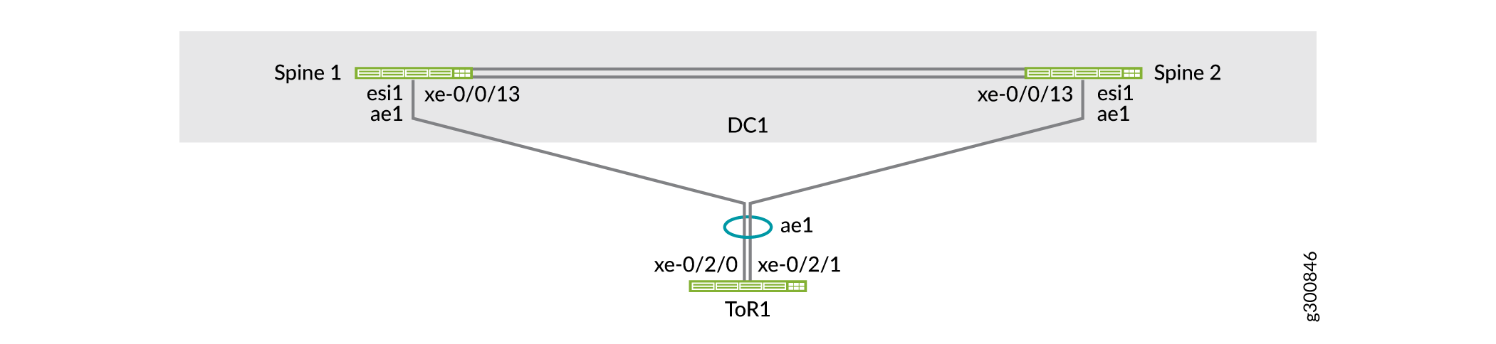
EVPN multihoming uses ESIs. An ESI is a mandatory attribute that enables EVPN LAG server multihoming. ESI values are encoded as 10-byte integers and are used to identify a multihomed segment. The same ESI value enabled on all spine switches connected to a ToR switch forms an EVPN LAG. This EVPN LAG supports active-active multihoming towards the ToR switch.
The ToR switches (implemented as ToR Virtual Chassis in this example) use a LAG to connect to the two spine switches. As shown in Figure 4, ToR1 is connected to the spine switches with LAG ae1. This LAG on the spine switches is enabled by the EVPN multihoming feature.
Configure Spine 1
Step-by-Step Procedure
By default, aggregated Ethernet interfaces are not created. You must set the number of aggregated Ethernet interfaces on the switch before you can configure them.
set chassis aggregated-devices ethernet device-count 15
set interfaces ae1 description "to ToR1"
set interfaces ae1 mtu 9216
Configure an ESI. Set it the same on both spine switches. Enable all-active modes.
set interfaces ae1 esi 00:00:00:00:00:00:00:00:01:01
set interfaces ae1 esi all-active
set interfaces ae1 aggregated-ether-options link-speed 10g
set interfaces ae1 aggregated-ether-options lacp active
set interfaces ae1 aggregated-ether-options lacp periodic fast
Note:You can also auto-derive ESI. In this example, you manually configure ESI.
Configure the LACP system ID. Set it the same on both spine switches to indicate to the ToR switches that uplinks to the two spine switches belong to the same LAG bundle. As a result, the ToR switches places the uplinks to the two spine switches in the same LAG bundle and load shares traffic across the member links.
set interfaces ae1 aggregated-ether-options lacp system-id 00:00:00:00:01:01
set interfaces ae1 unit 0 family ethernet-switching interface-mode trunk
set interfaces ae1 unit 0 family ethernet-switching vlan members VLAN-201
set interfaces ae1 unit 0 family ethernet-switching vlan members VLAN-202
set interfaces ae1 unit 0 family ethernet-switching vlan members VLAN-211
set interfaces ae1 unit 0 family ethernet-switching vlan members VLAN-212
Configure the physical interface on Spine 1 connected to ToR 1 as a member of the ae1 LAG.
set interfaces xe-0/0/13 ether-options 802.3ad ae1
Configure Spine 2
Step-by-Step Procedure
Set the number of aggregated Ethernet interfaces on the switch.
set chassis aggregated-devices ethernet device-count 15
set interfaces ae1 description "to ToR1"
set interfaces ae1 mtu 9216
Configure an ESI. Set it the same on both spine switches. Enable all-active modes.
set interfaces ae1 esi 00:00:00:00:00:00:00:00:01:01
set interfaces ae1 esi all-active
set interfaces ae1 aggregated-ether-options link-speed 10g
set interfaces ae1 aggregated-ether-options lacp active
set interfaces ae1 aggregated-ether-options lacp periodic fast
Configure the LACP system ID. Set it the same on both spine switches.
set interfaces ae1 aggregated-ether-options lacp system-id 00:00:00:00:01:01
set interfaces ae1 unit 0 family ethernet-switching interface-mode trunk
set interfaces ae1 unit 0 family ethernet-switching vlan members VLAN-201
set interfaces ae1 unit 0 family ethernet-switching vlan members VLAN-202
set interfaces ae1 unit 0 family ethernet-switching vlan members VLAN-211
set interfaces ae1 unit 0 family ethernet-switching vlan members VLAN-212
Configure the physical interface on Spine 2 connected to ToR 1 as a member of the ae1 LAG.
set interfaces xe-0/0/13 ether-options 802.3ad ae1
Configure ToR 1
Step-by-Step Procedure
By default, aggregated Ethernet interfaces are not created. You must set the number of aggregated Ethernet interfaces on the switch before you can configure them.
set chassis aggregated-devices ethernet device-count 4
Configure the aggregated Ethernet interfaces.
set interfaces xe-0/2/0 ether-options 802.3ad ae1
set interfaces xe-0/2/1 ether-options 802.3ad ae1

set interfaces ae1 aggregated-ether-options lacp active
set interfaces ae1 unit 0 family ethernet-switching interface-mode trunk
set interfaces ae1 unit 0 family ethernet-switching vlan members VLAN-201
set interfaces ae1 unit 0 family ethernet-switching vlan members VLAN-202
set interfaces ae1 unit 0 family ethernet-switching vlan members VLAN-211
set interfaces ae1 unit 0 family ethernet-switching vlan members VLAN-212
Configure the VLANs.
set vlans VLAN-201 vlan-id 201
set vlans VLAN-202 vlan-id 202
set vlans VLAN-211 vlan-id 211
set vlans VLAN-212 vlan-id 212
Verify EVPN Multihoming
Step-by-Step Procedure
Check the status of ae1 and the ESI associated with the LAG.
user@spine1> show interfaces ae1
Physical interface: ae1, Enabled, Physical link is Up
  Interface index: 689, SNMP ifIndex: 552
  Description: to ToR1
  Link-level type: Ethernet, MTU: 9216, Speed: 10Gbps, BPDU Error: None, Ethernet-Switching Error: None, MAC-REWRITE Error: None, Loopback: Disabled, Source filtering: Disabled, Flow control: Disabled, Minimum links needed: 1,
  Minimum bandwidth needed: 1bps
  Device flags   : Present Running
  Interface flags: SNMP-Traps Internal: 0x4000
  Current address: 3c:8c:93:2e:a9:80, Hardware address: 3c:8c:93:2e:a9:80
  Ethernet segment value: 00:00:00:00:00:00:00:00:01:01, Mode: all-active
  Last flapped   : 2019-11-10 14:50:49 PST (00:26:56 ago)
  Input rate     : 624 bps (0 pps)
  Output rate    : 936 bps (1 pps)
  ...
Verify that the members of ae1 are collecting and distributing.
user@spine1> show lacp interfaces ae1
Aggregated interface: ae1
    LACP state:       Role   Exp   Def  Dist  Col  Syn  Aggr  Timeout  Activity
      xe-0/0/13      Actor    No    No   Yes  Yes  Yes   Yes     Fast    Active
      xe-0/0/13    Partner    No    No   Yes  Yes  Yes   Yes     Fast    Active
    LACP protocol:        Receive State  Transmit State          Mux State
      xe-0/0/13                 Current   Fast periodic Collecting distributing
Verify the status of EVPN Multihoming in the EVPN instance is
Resolvedon Spine 1. You can also see which spine switch is the designated forwarder for BUM traffic.user@spine1> show evpn instance extensive Instance: __default_evpn__ Route Distinguisher: 192.168.255.13:0 Number of bridge domains: 0 Number of neighbors: 1 Address MAC MAC+IP AD IM ES Leaf-label 192.168.255.12 0 0 0 0 2 Instance: default-switch Route Distinguisher: 192.168.255.13:1 Encapsulation type: VXLAN Duplicate MAC detection threshold: 5 Duplicate MAC detection window: 180 MAC database status Local Remote MAC advertisements: 6 10 MAC+IP advertisements: 10 10 Default gateway MAC advertisements: 8 0 Number of local interfaces: 5 (3 up) Interface name ESI Mode Status AC-Role .local..6 00:00:00:00:00:00:00:00:00:00 single-homed Up Root ae1.0 00:00:00:00:00:00:00:00:01:01 all-active Up Root ... Number of neighbors: 1 Address MAC MAC+IP AD IM ES Leaf-label 192.168.255.12 10 10 8 4 0 Number of ethernet segments: 10 ESI: 00:00:00:00:00:00:00:00:01:01 Status: Resolved by IFL ae1.0 Local interface: ae1.0, Status: Up/Forwarding Number of remote PEs connected: 1 Remote PE MAC label Aliasing label Mode 192.168.255.12 5212 0 all-active DF Election Algorithm: MOD based Designated forwarder: 192.168.255.13 Backup forwarder: 192.168.255.12 Last designated forwarder update: Nov 10 14:50:49Verify that all member links of the ae1 interface are collecting and distributing on ToR 1.
user@tor1> show lacp interfaces
Aggregated interface: ae1
    LACP state:       Role   Exp   Def  Dist  Col  Syn  Aggr  Timeout  Activity
      xe-0/2/0       Actor    No    No   Yes  Yes  Yes   Yes     Fast    Active
      xe-0/2/0     Partner    No    No   Yes  Yes  Yes   Yes     Fast    Active
      xe-0/2/1       Actor    No    No   Yes  Yes  Yes   Yes     Fast    Active
      xe-0/2/1     Partner    No    No   Yes  Yes  Yes   Yes     Fast    Active
    LACP protocol:        Receive State  Transmit State          Mux State
      xe-0/2/0                  Current   Fast periodic Collecting distributing
      xe-0/2/1                  Current   Fast periodic Collecting distributing
Configure Multihoming for the Servers
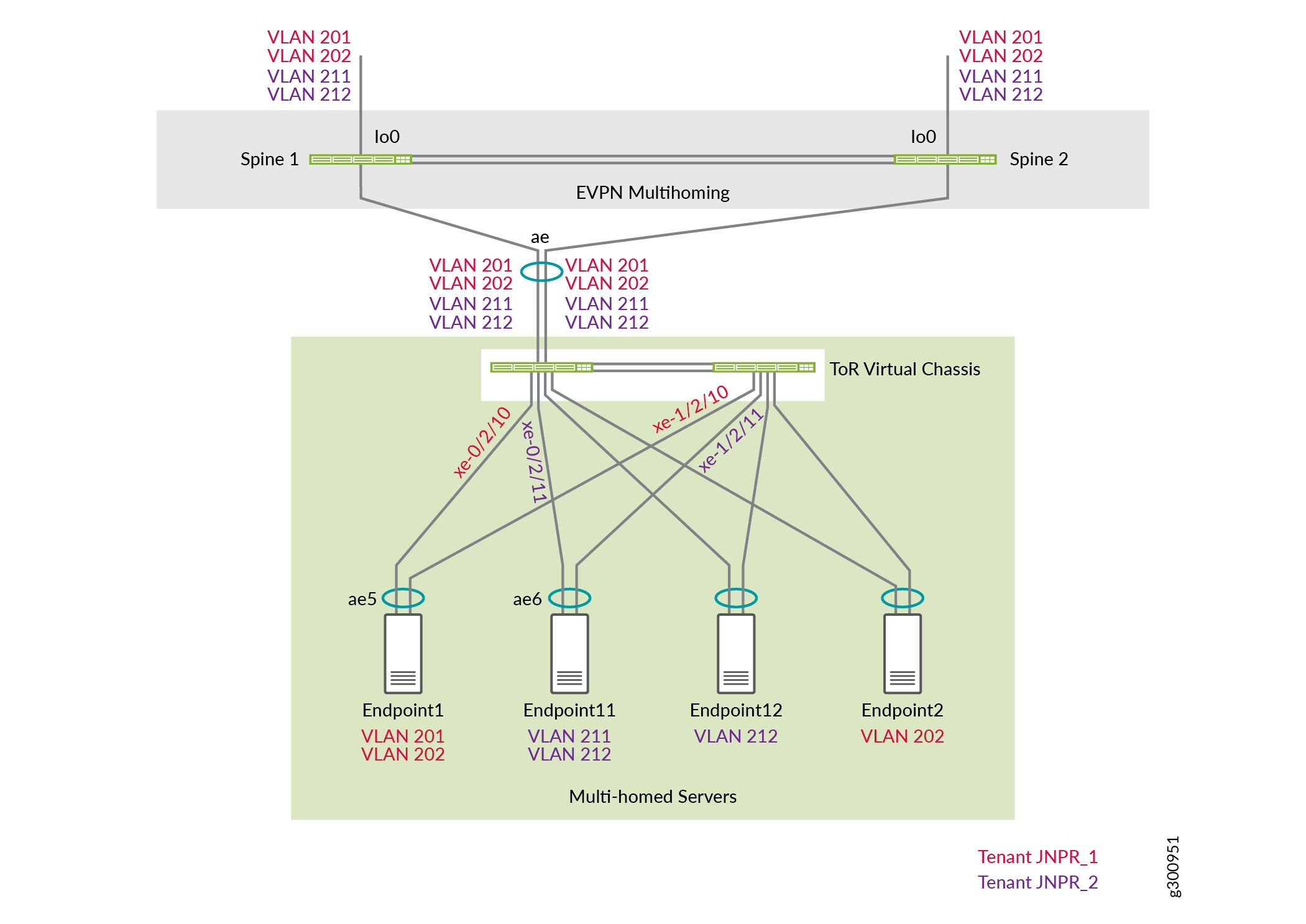
Multihome the servers to the ToR Virtual Chassis for redundancy and load sharing. The servers use LAG to connect to the two ToR Virtual Chassis member switches.
As shown in Figure 5, Endpoint 1 is connected to the ToR Virtual Chassis through LAG ae5 and belongs to the JNPR_1 tenant. Endpoint 11 is connected to the ToR Virtual Chassis through LAG ae6 and belongs to the JNPR_2 tenant.
Configure ToR 1
Step-by-Step Procedure
Since the ToR switches are configured in a Virtual Chassis, you only need to commit the configuration on the primary switch. In this example, ToR 1 is the primary switch.
Configure LAG on the interfaces connected to Endpoint 1: interface xe-0/2/10 on ToR 1 and interface xe-1/2/10 on ToR 2. Endpoint 1 belongs to VLANs 201 and 202.
set interfaces xe-0/2/10 ether-options 802.3ad ae5
set interfaces xe-1/2/10 ether-options 802.3ad ae5

set interfaces ae5 aggregated-ether-options lacp active
set interfaces ae5 description "Connected to Endpoint1"
set interfaces ae5 unit 0 family ethernet-switching interface-mode trunk
set interfaces ae5 unit 0 family ethernet-switching vlan members VLAN-201
set interfaces ae5 unit 0 family ethernet-switching vlan members VLAN-202
Configure LAG on the interfaces connected to Endpoint 11. Endpoint 11 belongs to VLANs 211 and 212.
set interfaces xe-0/2/11 ether-options 802.3ad ae6
set interfaces xe-1/2/11 ether-options 802.3ad ae6

set interfaces ae6 aggregated-ether-options lacp active
set interfaces ae6 description "Connected to Endpoint11"
set interfaces ae6 unit 0 family ethernet-switching interface-mode trunk
set interfaces ae6 unit 0 family ethernet-switching vlan members VLAN-211
set interfaces ae6 unit 0 family ethernet-switching vlan members VLAN-212
Verify Server Connectivity
Use this section to verify the servers are connected to each other through the ToR and spine switches. How you do this depends on whether they are part of the same VLAN or two different VLANs.
We recommend multihoming your servers to the ToR switches for redundancy and load sharing as described in the previous section. This section shows single-homed servers for simplicity.
Verify Intra-VLAN Server Connectivity
Step-by-Step Procedure
Verify the MAC addresses of both endpoints appear in the Ethernet switching table on both the ToR switches.
user@tor1> show ethernet-switching table MAC flags (S - static MAC, D - dynamic MAC, L - locally learned, P - Persistent static, C - Control MAC SE - statistics enabled, NM - non configured MAC, R - remote PE MAC, O - ovsdb MAC) Ethernet switching table : 4 entries, 4 learned Routing instance : default-switch Vlan MAC MAC Age Logical NH RTR name address flags interface Index ID VLAN-201 f4:b5:2f:40:9f:01 D - ae1.0 0 0 VLAN-202 00:10:94:00:01:01 D - xe-0/2/2.0 0 0 VLAN-202 00:10:94:00:01:02 D - ae1.0 0 0 VLAN-202 3c:8c:93:2e:a8:c0 D - ae1.0 0 0user@tor2> show ethernet-switching table MAC flags (S - static MAC, D - dynamic MAC, L - locally learned, P - Persistent static, C - Control MAC SE - statistics enabled, NM - non configured MAC, R - remote PE MAC, O - ovsdb MAC) Ethernet switching table : 4 entries, 4 learned Routing instance : default-switch Vlan MAC MAC Age Logical NH RTR name address flags interface Index ID VLAN-201 f4:b5:2f:40:9f:01 D - ae1.0 0 0 VLAN-202 00:10:94:00:01:01 D - xe-0/2/2.0 0 0 VLAN-202 00:10:94:00:01:02 D - ae1.0 0 0 VLAN-202 3c:8c:93:2e:a8:c0 D - ae1.0 0 0Verify that the two MAC addresses appear in the Ethernet Switching table on both the spine switches. The two MAC addresses are learned from the ToR switches over the LAG (ae1 and ae2) connected to each ToR switch. The MAC flags
DL,DR, andDLRindicate whether traffic for the MAC address was learned locally by the spine switch, by the remote spine switch, or by both the spine switches.user@spine1> show ethernet-switching table vlan-id 202 MAC flags (S - static MAC, D - dynamic MAC, L - locally learned, P - Persistent static SE - statistics enabled, NM - non configured MAC, R - remote PE MAC, O - ovsdb MAC) Ethernet switching table : 4 entries, 4 learned Routing instance : default-switch Vlan MAC MAC Logical Active name address flags interface source VLAN-202 00:00:5e:00:01:01 DR esi.1723 05:00:00:fe:4c:00:00:14:52:00 VLAN-202 00:10:94:00:01:01 DR ae1.0 VLAN-202 00:10:94:00:01:02 DL ae2.0 VLAN-202 3c:8c:93:2e:da:c0 D vtep.32769 192.168.255.12user@spine2> show ethernet-switching table vlan-id 202 MAC flags (S - static MAC, D - dynamic MAC, L - locally learned, P - Persistent static SE - statistics enabled, NM - non configured MAC, R - remote PE MAC, O - ovsdb MAC) Ethernet switching table : 4 entries, 4 learned Routing instance : default-switch Vlan MAC MAC Logical Active name address flags interface source VLAN-202 00:00:5e:00:01:01 DR esi.1723 05:00:00:fe:4c:00:00:14:52:00 VLAN-202 00:10:94:00:01:01 DR ae1.0 VLAN-202 00:10:94:00:01:02 DL ae2.0 VLAN-202 3c:8c:93:2e:da:c0 D vtep.32769 192.168.255.12Verify the first MAC address is in the EVPN database on Spine 1. This output indicates that the MAC address was learned locally by this spine switch over the ESI 00:00:00:00:00:00:00:00:01:02 and LAG ae2. This MAC address is advertised in EVPN to the other spine switch.
user@spine1> show evpn database mac-address 00:10:94:00:01:02 extensive
Instance: default-switch

VN Identifier: 5202, MAC address: 00:10:94:00:01:02
  State: 0x0
  Source: 00:00:00:00:00:00:00:00:01:02, Rank: 1, Status: Active
    Local origin: ae2.0
    Mobility sequence number: 0 (minimum origin address 192.168.255.13)
    Timestamp: Nov 10 16:48:41 (0x5dc8afe9)
    State: <Local-MAC-Only Local-To-Remote-Adv-Allowed>
    MAC advertisement route status: Created
    History db:
      Time                  Event
      Nov 10 16:48:41 2019  Updating output state (change flags 0x20 <ESI-Added>)
      Nov 10 16:48:41 2019  Active ESI changing (not assigned -> 00:00:00:00:00:00:00:00:01:02)
      Nov 10 16:48:41 2019  Creating all output state
      Nov 10 16:48:41 2019  Creating MAC advertisement route
      Nov 10 16:48:41 2019  Adding to instance ESI list
      Nov 10 16:48:41 2019  Clearing change flags <ESI-Added>
      Nov 10 16:48:41 2019  Clearing change flags <Intf ESI-Local-State>
      Nov 10 16:48:42 2019  Updating output state (change flags 0x0)
      Nov 10 16:48:42 2019  Active ESI unchanged (00:00:00:00:00:00:00:00:01:02)
      Nov 10 16:48:42 2019  Updating output state (change flags 0x0)
Verify the second MAC address is in the EVPN database on Spine 1. This MAC address was learned by the remote spine switch and advertised to the local spine switch over EVPN. This output also shows that this MAC address is mapped to ESI 00:00:00:00:00:00:00:00:01:01. Traffic destined for this MAC address can be switched locally to ToR 1 using the same Ethernet segment.
user@spine1> show evpn database mac-address 00:10:94:00:01:01 extensive
Instance: default-switch

VN Identifier: 5202, MAC address: 00:10:94:00:01:01
  State: 0x0
  Source: 00:00:00:00:00:00:00:00:01:01, Rank: 1, Status: Active
    Remote origin: 192.168.255.12
    Mobility sequence number: 0 (minimum origin address 192.168.255.12)
    Timestamp: Nov 10 16:48:41 (0x5dc8afe9)
    State: <Remote-To-Local-Adv-Done>
    MAC advertisement route status: Not created (no local state present)
    History db:
      Time                  Event
      Nov 10 16:48:41 2019  Adding to instance ESI list
      Nov 10 16:48:41 2019  Clearing change flags <ESI-Added>
      Nov 10 16:48:41 2019  Clearing change flags <ESI-Peer-Added ESI-Remote-Peer-Com-Chg>
      Nov 10 16:48:42 2019  Updating output state (change flags 0x0)
      Nov 10 16:48:42 2019  Active ESI unchanged (00:00:00:00:00:00:00:00:01:01)
      Nov 10 16:48:42 2019  Updating output state (change flags 0x0)
      Nov 10 16:48:42 2019  Advertisement route cannot be created (no local state present)
      Nov 10 16:48:42 2019  ESI 00:00:00:00:00:00:00:00:01:01, peer 192.168.255.12 per-ES AD route not rcvd, remote peer found
      Nov 10 16:48:42 2019  Sent MAC add with NH 0, interface ae1.0 (index 0), RTT 6, remote addr 192.168.255.12, ESI 0101, VLAN 0, VNI 5202, flags 0x0, timestamp 0x5dc8afe9 to L2ALD
      Nov 10 16:48:42 2019  Sent peer 192.168.255.12 record created
Verify the EVPN routes on Spine 1. This output shows that these MAC addresses are advertised by the spine switches as BGP routes.
user@spine1> show route table bgp.evpn.0 evpn-mac-address 00:10:94:00:01:01
bgp.evpn.0: 75 destinations, 75 routes (75 active, 0 holddown, 0 hidden)
Restart Complete
+ = Active Route, - = Last Active, * = Both

2:192.168.255.13:1::5202::00:10:94:00:01:01/304 MAC/IP
                   *[EVPN/170] 00:01:52
                       Indirect
user@spine1> show route table bgp.evpn.0 evpn-mac-address 00:10:94:00:01:02
bgp.evpn.0: 75 destinations, 75 routes (75 active, 0 holddown, 0 hidden)
Restart Complete
+ = Active Route, - = Last Active, * = Both

2:192.168.255.13:1::5202::00:10:94:00:01:02/304 MAC/IP
                   *[EVPN/170] 00:02:02
                       Indirect
Verify the EVPN routes on Spine 2. This output shows the BGP routes received the IBGP peering with Spine 1. Let us look at these routes in detail.
user@spine2> show route receive-protocol bgp 192.168.255.13
inet.0: 13 destinations, 14 routes (13 active, 0 holddown, 0 hidden)
Restart Complete

JNPR_1_VRF.inet.0: 9 destinations, 11 routes (9 active, 0 holddown, 0 hidden)

:vxlan.inet.0: 9 destinations, 9 routes (9 active, 0 holddown, 0 hidden)
Restart Complete

JNPR_2_VRF.inet.0: 9 destinations, 11 routes (9 active, 0 holddown, 0 hidden)

mpls.0: 2 destinations, 2 routes (2 active, 0 holddown, 0 hidden)
Restart Complete

inet6.0: 1 destinations, 1 routes (1 active, 0 holddown, 0 hidden)
Restart Complete

JNPR_1_VRF.inet6.0: 1 destinations, 1 routes (1 active, 0 holddown, 0 hidden)

JNPR_2_VRF.inet6.0: 1 destinations, 1 routes (1 active, 0 holddown, 0 hidden)

bgp.evpn.0: 75 destinations, 75 routes (75 active, 0 holddown, 0 hidden)
Restart Complete
  Prefix                  Nexthop              MED     Lclpref    AS path
  1:192.168.255.13:0::0101::FFFF:FFFF/192 AD/ESI
*                         192.168.255.13               100        I
  1:192.168.255.13:0::0102::FFFF:FFFF/192 AD/ESI
*                         192.168.255.13               100        I
...
  1:192.168.255.13:0::050000fe4c0000145c00::FFFF:FFFF/192 AD/ESI
*                         192.168.255.13               100        I
  1:192.168.255.13:1::0101::0/192 AD/EVI
*                         192.168.255.13               100        I
  1:192.168.255.13:1::0102::0/192 AD/EVI
*                         192.168.255.13               100        I
...
The two Type 1 routes emphasized above show that Spine 1 is connected to two Ethernet Segments (ES). The ESI numbers are 0101 and 0102.
...
  2:192.168.255.13:1::5202::00:00:5e:00:01:01/304 MAC/IP
*                         192.168.255.13               100        I
  2:192.168.255.13:1::5202::00:10:94:00:01:01/304 MAC/IP
*                         192.168.255.13               100        I
  2:192.168.255.13:1::5202::00:10:94:00:01:02/304 MAC/IP
*                         192.168.255.13               100        I
...
These two routes are Type 2 routes shown above are advertised by Spine 1. They show that the two MAC addresses are reachable from Spine 1.
Verify the control plane for the following MAC addresses on Spine 1.
user@spine1> show route table bgp.evpn.0 evpn-mac-address 00:10:94:00:01:01 bgp.evpn.0: 78 destinations, 78 routes (78 active, 0 holddown, 0 hidden) Restart Complete + = Active Route, - = Last Active, * = Both 2:192.168.255.13:1::5202::00:10:94:00:01:01/304 MAC/IP *[EVPN/170] 00:11:49 Indirectuser@spine1> show route table bgp.evpn.0 evpn-mac-address 00:10:94:00:01:02 bgp.evpn.0: 78 destinations, 78 routes (78 active, 0 holddown, 0 hidden) Restart Complete + = Active Route, - = Last Active, * = Both 2:192.168.255.13:1::5202::00:10:94:00:01:02/304 MAC/IP *[EVPN/170] 00:11:52 IndirectVerify the forwarding table entries for these MAC addresses on Spine 1. The following output shows that the local aggregated Ethernet interface is used for switching traffic destined for these MAC addresses.
user@spine1> show route forwarding-table destination 00:10:94:00:01:01
Routing table: default-switch.bridge
Bridging domain: VLAN-202.bridge
VPLS:
Enabled protocols: Bridging, ACKed by all peers,
Destination        Type RtRef Next hop           Type Index    NhRef Netif
00:10:94:00:01:01/48 user     0                  ucst     1710     7 ae1.0
user@spine1> show route forwarding-table destination 00:10:94:00:01:02
Routing table: default-switch.bridge
Bridging domain: VLAN-202.bridge
VPLS:
Enabled protocols: Bridging, ACKed by all peers,
Destination        Type RtRef Next hop           Type Index    NhRef Netif
00:10:94:00:01:02/48 user     0                  ucst     1754     9 ae2.0
Test what happens when an uplink fails. If an uplink from ToR 1 fails, the output shows that the state at that interface is
Detached.user@spine1> show lacp interfaces ae1 Aggregated interface: ae1 LACP state: Role Exp Def Dist Col Syn Aggr Timeout Activity xe-0/0/13 Actor No Yes No No No Yes Fast Active xe-0/0/13 Partner No Yes No No No Yes Fast Passive LACP protocol: Receive State Transmit State Mux State xe-0/0/13 Port disabled No periodic DetachedFigure 6 shows the topology when the interface connected to ToR 1 on Spine 1 is down.
Figure 6: Topology When Uplink Fails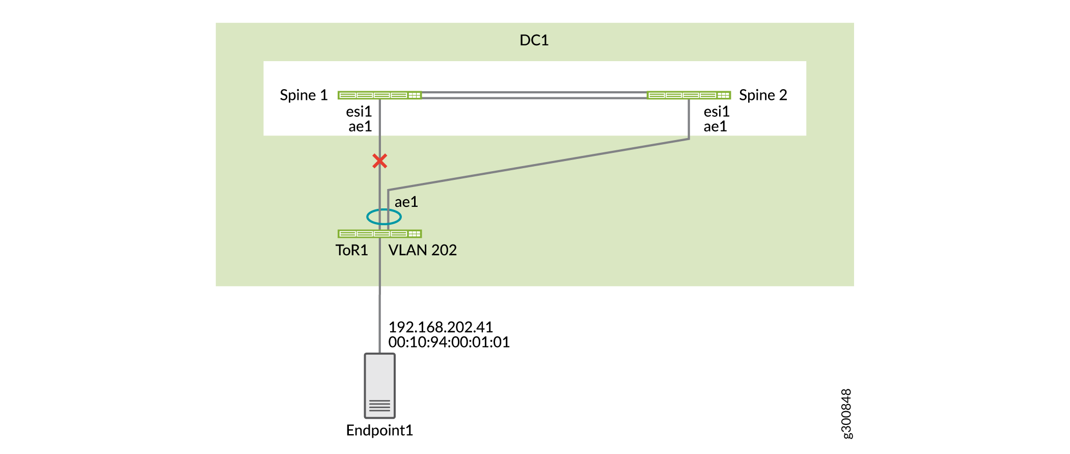
Verify that Spine 1 is now learning this MAC address from Spine 2 since Spine 1 does not have a direct connection to ToR 1.
user@spine1> show route table bgp.evpn.0 evpn-mac-address 00:10:94:00:01:01
bgp.evpn.0: 76 destinations, 76 routes (76 active, 0 holddown, 0 hidden)
Restart Complete
+ = Active Route, - = Last Active, * = Both

2:192.168.255.12:1::5202::00:10:94:00:01:01/304 MAC/IP
                   *[BGP/170] 00:01:05, localpref 100, from 192.168.255.12
                      AS path: I, validation-state: unverified
                       to 192.168.100.4 via et-0/0/50.0
                    >  to 192.168.100.6 via et-0/0/51.0
The forwarding table details on Spine 1 show that the traffic destined for this MAC address is sent to Spine 2.
user@spine1> show route forwarding-table destination 00:10:94:00:01:01 extensive
Routing table: default-switch.bridge [Index 6]
Bridging domain: VLAN-202.bridge [Index 6]
VPLS:
Enabled protocols: Bridging, ACKed by all peers,

Destination:  00:10:94:00:01:01/48
  Learn VLAN: 0                        Route type: user
  Route reference: 0                   Route interface-index: 560
  Multicast RPF nh index: 0
  P2mpidx: 0
  IFL generation: 514                  Epoch: 0
  Sequence Number: 0                   Learn Mask: 0x4000000000000000010000000000000000000000
  L2 Flags: control_dyn
  Flags: sent to PFE
  Nexthop:
  Next-hop type: composite             Index: 1724     Reference: 26
  Next-hop type: indirect              Index: 524289   Reference: 3
  Next-hop type: unilist               Index: 524288   Reference: 6
  Nexthop: 192.168.100.4
  Next-hop type: unicast               Index: 1708     Reference: 4
  Next-hop interface: et-0/0/50.0      Weight: 0x0
  Nexthop: 192.168.100.6
  Next-hop type: unicast               Index: 1709     Reference: 4
  Next-hop interface: et-0/0/51.0      Weight: 0x0
Verify Inter-VLAN Server Connectivity
Step-by-Step Procedure
On Spine 1, verify that the two MAC addresses are in different VLANs.
user@spine1> show ethernet-switching table | match 00:10:94:00:11:11
   VLAN-201            00:10:94:00:11:11   DLR      ae1.0
user@spine1> show ethernet-switching table | match 00:10:94:00:01:02
   VLAN-202            00:10:94:00:01:02   DL       ae2.0
On Spine 1, verify the ARP resolution for the two endpoints.
user@spine1> show arp no-resolve | match 00:10:94:00:11:11
00:10:94:00:11:11 192.168.201.41  irb.201 [ae1.0]          permanent remote
user@spine1> show arp no-resolve | match 00:10:94:00:01:02
00:10:94:00:01:02 192.168.202.42  irb.202 [ae2.0]          permanent remote
On Spine 1, check the control plane learning for the MAC address 00:10:94:00:11:11. You can see that there is a MAC route for the MAC address and a MAC/IP route for this MAC address.
user@spine1> show route table bgp.evpn.0 evpn-mac-address 00:10:94:00:11:11
bgp.evpn.0: 82 destinations, 82 routes (82 active, 0 holddown, 0 hidden)
Restart Complete
+ = Active Route, - = Last Active, * = Both

2:192.168.255.12:1::5201::00:10:94:00:11:11/304 MAC/IP
                   *[BGP/170] 00:08:43, localpref 100, from 192.168.255.12
                      AS path: I, validation-state: unverified
                       to 192.168.100.4 via et-0/0/50.0
                    >  to 192.168.100.6 via et-0/0/51.0
2:192.168.255.13:1::5201::00:10:94:00:11:11/304 MAC/IP
                   *[EVPN/170] 00:09:01
                       Indirect
2:192.168.255.12:1::5201::00:10:94:00:11:11::192.168.201.41/304 MAC/IP
                   *[BGP/170] 00:08:43, localpref 100, from 192.168.255.12
                      AS path: I, validation-state: unverified
                       to 192.168.100.4 via et-0/0/50.0
                    >  to 192.168.100.6 via et-0/0/51.0
2:192.168.255.13:1::5201::00:10:94:00:11:11::192.168.201.41/304 MAC/IP
                   *[EVPN/170] 00:09:01
                       Indirect
Verify the forwarding table entries for these MAC addresses. Since Spine 1 is connected to both ToR switches locally, the traffic is switched locally to the corresponding ToR switch from Spine 1.
user@spine1> show route forwarding-table destination 00:10:94:00:11:11
Routing table: default-switch.bridge
Bridging domain: VLAN-201.bridge
VPLS:
Enabled protocols: Bridging, ACKed by all peers,
Destination        Type RtRef Next hop           Type Index    NhRef Netif
00:10:94:00:11:11/48 user     0                  ucst     1710     8 ae1.0
user@spine1> show route forwarding-table destination 00:10:94:00:01:02
Routing table: default-switch.bridge
Bridging domain: VLAN-202.bridge
VPLS:
Enabled protocols: Bridging, ACKed by all peers,
Destination        Type RtRef Next hop           Type Index    NhRef Netif
00:10:94:00:01:02/48 user     0                  ucst     1754    10 ae2.0
What's Next
You have configured and verified a collapsed spine architecture for your first data center. If needed, repeat the configuration on the devices in the second data center.
Go to the next page to configure advanced security and connect your data centers.
Split-Brain State
How to Prevent a Split-Brain State
Problem
If the links between the spine switches are down, causing the BGP peering to go down, both spine switches are active and forwarding. The downstream aggregated Ethernet interfaces are active and forwarding. This scenario is known as a split-brain state and can cause multiple problems.
Solution
To prevent this issue from occurring, choose one spine switch to be the standby switch.
We also recommend:
-
Using at least two links between the spine switches. This makes it less likely all the links between the spine switches will go down.
-
Multihoming all servers. If there is a single-homed server on one of the spine switches, the server could be unreachable.
What's Next
You have configured and verified a collapsed spine architecture for your first data center. If needed, repeat the configuration on the devices in the second data center.
Go to the next page to configure advanced security and connect your data centers.