Secure Tunnel Interface in a Virtual Router
Read this topic to learn about secure tunnel (st0) interface in a virtual router.
A secure tunnel interface (st0) is an internal interface that is used by route-based VPNs to route cleartext traffic to an IPsec VPN tunnel.
Understanding Virtual Router Support for Route-Based VPNs
This feature includes routing-instance support for route-based VPNs. In previous releases, when an st0 interface was put in a nondefault routing instance, the VPN tunnels on this interface did not work properly. You can place the st0 interface in a routing instance and configure each unit in point-to-point mode or multipoint mode. Therefore, VPN traffic now works correctly in a nondefault VR. You can now configure different subunits of the st0 interface in different routing instances. The following functions are supported for nondefault routing instances:
-
Manual key management
-
Transit traffic
-
Self-traffic
-
VPN monitoring
-
Hub-and-spoke VPNs
-
Encapsulating Security Payload (ESP) protocol
-
Authentication Header (AH) protocol
-
Aggressive mode or main mode
-
st0 anchored on the loopback (lo0) interface
-
Maximum number of virtual routers (VRs) supported on an SRX Series Firewall
-
Applications such as Application Layer Gateway (ALG), Intrusion Detection and Prevention (IDP), and Content Security
-
Dead peer detection (DPD)
-
Chassis cluster active/backup
-
Open Shortest Path First (OSPF) over st0
-
Routing Information Protocol (RIP) over st0
Understanding Virtual Router Limitations
When you configure VPN on SRX Series Firewalls, overlapping of IP addresses across virtual routers is supported with the following limitations:
An IKE external interface address cannot overlap with any other virtual router.
An internal or trust interface address can overlap across any other virtual router.
An st0 interface address cannot overlap in route-based VPN in point-to-multipoint tunnels such as NHTB.
An st0 interface address can overlap in route-based VPN in point-to-point tunnels.
See Also
Example: Configuring an st0 Interface in a Virtual Router
This example shows how to configure an st0 interface in a virtual router.
Requirements
Before you begin, configure the interfaces and assign the interfaces to security zones. See "Security Zones Overview".
Overview
In this example, you perform the following operations:
Configure the interfaces.
Configure IKE Phase 1 proposals.
Configure IKE policies, and reference the proposals.
Configure an IKE gateway, and reference the policy.
Configure Phase 2 proposals.
Configure policies, and reference the proposals.
Configure AutoKey IKE, and reference the policy and gateway.
Configure the security policy.
Configure the routing instance.
Configure the VPN bind to tunnel interface.
Configure the routing options.
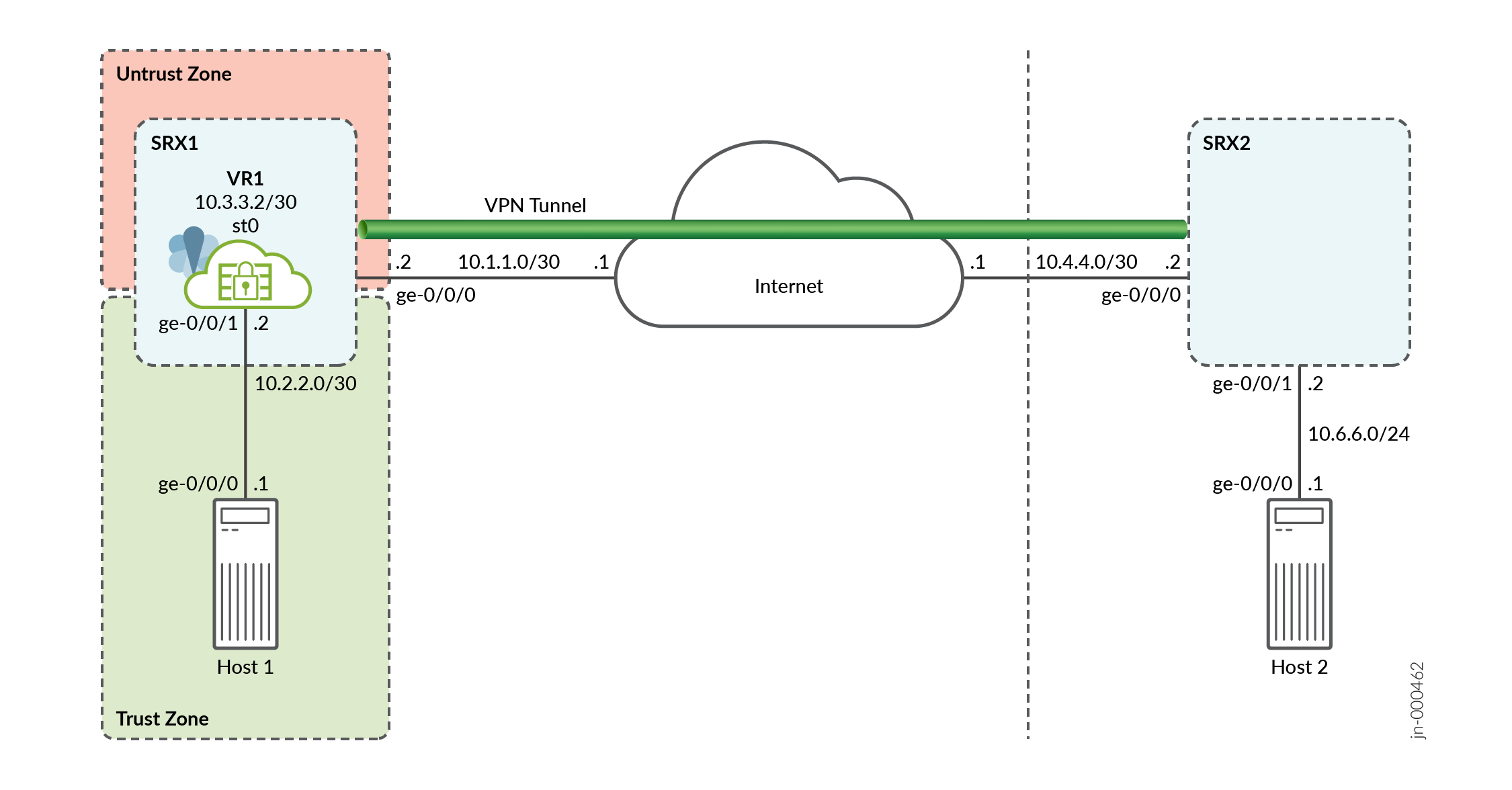
Figure 1 shows the topology used in this example.
Following tables show the configuration parameters.
|
Feature |
Name |
Configuration Parameters |
|---|---|---|
|
Interfaces |
ge-0/0/0.0 |
10.1.1.2/30 |
|
ge-0/0/1.0 |
10.2.2.2/30 |
|
|
st0.0 (tunnel interface) |
10.3.3.2/30 |
|
|
Routing instance (Virtual Router) |
VR1 |
ge-0/0/1.0 st0.0 |
|
Static routes |
10.6.6.0/24 |
The next hop is st0.0. |
|
Security zones |
trust |
|
|
untrust |
|
|
Feature |
Name |
Configuration Parameters |
|---|---|---|
|
Proposal |
first_ikeprop |
|
|
Policy |
first_ikepol |
|
|
Gateway |
first |
|
|
Feature |
Name |
Configuration Parameters |
|---|---|---|
|
Proposal |
first_ipsecprop |
|
|
Policy |
first_ipsecpol |
|
|
VPN |
first_vpn |
|
Configuration
Procedure
CLI Quick Configuration
To quickly configure this example, copy the
following commands, paste them into a text file, remove any line breaks,
change any details necessary to match your network configuration,
copy and paste the commands into the CLI at the [edit] hierarchy
level, and then enter commit from configuration mode.
set interfaces ge-0/0/0 unit 0 family inet address 10.1.1.2/30
set interfaces ge-0/0/1 unit 0 family inet address 10.2.2.2/30
set interfaces st0 unit 0 family inet address 10.3.3.2/30
set security zones security-zone trust interfaces ge-0/0/1
set security zones security-zone untrust interfaces ge-0/0/0
set security zones security-zone untrust interfaces st0.0
set security ike proposal first_ikeprop authentication-method pre-shared-keys
set security ike proposal first_ikeprop dh-group group2
set security ike proposal first_ikeprop authentication-algorithm md5
set security ike proposal first_ikeprop encryption-algorithm 3des-cbc
set security ike policy first_ikepol mode main
set security ike policy first_ikepol proposals first_ikeprop
set security ike policy first_ikepol pre-shared-key ascii-text "$ABC123"
set security ike gateway first ike-policy first_ikepol
set security ike gateway first address 10.4.4.2
set security ike gateway first external-interface ge-0/0/0.0
set security ipsec proposal first_ipsecprop protocol esp
set security ipsec proposal first_ipsecprop authentication-algorithm hmac-md5-96
set security ipsec proposal first_ipsecprop encryption-algorithm 3des-cbc
set security ipsec policy first_ipsecpol perfect-forward-secrecy keys group1
set security ipsec policy first_ipsecpol proposals first_ipsecprop
set security ipsec vpn first_vpn bind-interface st0.0
set security ipsec vpn first_vpn ike gateway first
set security ipsec vpn first_vpn ike ipsec-policy first_ipsecpol
set security ipsec vpn first_vpn establish-tunnels immediately
set security policies from-zone trust to-zone untrust policy p1 match source-address any
set security policies from-zone trust to-zone untrust policy p1 match destination-address any
set security policies from-zone trust to-zone untrust policy p1 match application any
set security policies from-zone trust to-zone untrust policy p1 then permit
set security policies from-zone untrust to-zone trust policy p2 match source-address any
set security policies from-zone untrust to-zone trust policy p2 match destination-address any
set security policies from-zone untrust to-zone trust policy p2 match application any
set security policies from-zone untrust to-zone trust policy p2 then permit
set routing-instances VR1 instance-type virtual-router
set routing-instances VR1 interface ge-0/0/1.0
set routing-instances VR1 interface st0.0
set routing-instances VR1 routing-options static route 10.6.6.0/24 next-hop st0.0
Step-by-Step Procedure
The following example requires you to navigate various levels in the configuration hierarchy. For instructions on how to do that, see Using the CLI Editor in Configuration Mode in the Junos OS CLI User Guide.
To configure an st0 in a VR:
Configure the interfaces.
[edit]
user@host# set interfaces ge-0/0/0 unit 0 family inet address 10.1.1.2/30
user@host# set interfaces ge-0/0/1 unit 0 family inet address 10.2.2.2/30
user@host# set interfaces st0 unit 0 family inet address 10.3.3.2/30
-
Configure security zones.
[edit]
user@host# set security zones security-zone trust interfaces ge-0/0/1
user@host# set security zones security-zone untrust interfaces ge-0/0/0
user@host# set security zones security-zone untrust interfaces st0.0
Configure Phase 1 of the IPsec tunnel.
[edit security ike]
user@host# set proposal first_ikeprop authentication-method pre-shared-keys
user@host# set proposal first_ikeprop dh-group group2
user@host# set proposal first_ikeprop authentication-algorithm md5
user@host# set proposal first_ikeprop encryption-algorithm 3des-cbc
Configure the IKE policies, and reference the proposals.
[edit security ike]
user@host# set policy first_ikepol mode main
user@host# set policy first_ikepol proposals first_ikeprop
user@host# set policy first_ikepol pre-shared-key ascii-text "$ABC123"
Configure the IKE gateway, and reference the policy.
[edit security ike]
user@host# set gateway first ike-policy first_ikepol
user@host# set gateway first address 10.4.4.2
user@host# set gateway first external-interface ge-0/0/0.0
Configure Phase 2 of the IPsec tunnel.
[edit security ipsec]
user@host# set proposal first_ipsecprop protocol esp
user@host# set proposal first_ipsecprop authentication-algorithm hmac-md5-96
user@host# set proposal first_ipsecprop encryption-algorithm 3des-cbc
Configure the policies, and reference the proposals.
[edit security ipsec]
user@host# set policy first_ipsecpol perfect-forward-secrecy keys group1
user@host# set policy first_ipsecpol proposals first_ipsecprop
Configure AutoKey IKE, and reference the policy and gateway.
[edit security ipsec]
user@host# set vpn first_vpn ike gateway first
user@host# set vpn first_vpn ike ipsec-policy first_ipsecpol
user@host# set vpn first_vpn establish-tunnels immediately
Configure the VPN bind to tunnel interface.
[edit security ipsec]
user@host# set vpn first_vpn bind-interface st0.0
Configure the security policy.
[edit security policies]
user@host# set from-zone trust to-zone untrust policy p1 match source-address any
user@host# set from-zone trust to-zone untrust policy p1 match destination-address any
user@host# set from-zone trust to-zone untrust policy p1 match application any
user@host# set from-zone trust to-zone untrust policy p1 then permit
user@host# set from-zone untrust to-zone trust policy p2 match source-address any
user@host# set from-zone untrust to-zone trust policy p2 match destination-address any
user@host# set from-zone untrust to-zone trust policy p2 match application any
user@host# set from-zone untrust to-zone trust policy p2 then permit
Configure the st0 in the routing instance.
[edit routing-instances]
user@host# set VR1 instance-type virtual-router
user@host# set VR1 interface ge-0/0/1.0
user@host# set VR1 interface st0.0
Configure the routing options.
[edit routing-instances VR1 routing-options]
user@host# set static route 10.6.6.0/24 next-hop st0.0
Results
From configuration mode, confirm your configuration
by entering the show security and show routing-instances commands. If the output does not display the intended configuration,
repeat the configuration instructions in this example to correct it.
user@host# show security
    ike {
    proposal first_ikeprop {
        authentication-method pre-shared-keys;
        dh-group group2;
        authentication-algorithm md5;
        encryption-algorithm 3des-cbc;
    }
    policy first_ikepol {
        mode main;
        proposals first_ikeprop;
        pre-shared-key ascii-text "$ABC123"; ## SECRET-DATA
    }
    gateway first {
        ike-policy first_ikepol;
        address 10.4.4.2;
        external-interface ge-0/0/0.0;
    }
}
    ipsec {
        proposal first_ipsecprop {
            protocol esp;
            authentication-algorithm hmac-md5-96;
            encryption-algorithm 3des-cbc;
        }
        policy first_ipsecpol {
            perfect-forward-secrecy {
                keys group1;
            }
            proposals first_ipsecprop;
        }
        vpn first_vpn {
            bind-interface st0.0;
            ike {
                gateway first;
                ipsec-policy first_ipsecpol;
            }
            establish-tunnels immediately;
        }
    }
policies {
    from-zone trust to-zone untrust {
        policy p1 {
            match {
                source-address any;
                destination-address any;
                application any;
            }
            then {
                permit;
            }
        }
    }
        from-zone untrust to-zone trust {
            policy p2 {
                match {
                    source-address any;
                    destination-address any;
                    application any;
                }
                then {
                    permit;
                }
            }
        }
zones {
    security-zone trust {
        interfaces {
            ge-0/0/1.0;
        }
    }
    security-zone untrust {
        interfaces {
            ge-0/0/0.0;
            st0.0;
        }
    }
}

user@host# show routing-instances
        VR1 {
            instance-type virtual-router;
            interface ge-0/0/1.0;
            interface st0.0;
            routing-options {
            static {
            route 10.6.6.0/24 next-hop st0.0;
        }
    }
}
If you are done configuring the device, enter commit from configuration mode.
Verification
To confirm that the configuration is working properly, perform this task:
Verifying an st0 interface in the Virtual Router
Purpose
Verify the st0 interface in the virtual router.
Action
From operational mode, enter the show interfaces
st0.0 detail command. The number listed for routing table corresponds
to the order that the routing tables in the show route all command.
Change History Table
Feature support is determined by the platform and release you are using. Use Feature Explorer to determine if a feature is supported on your platform.