Route-Based VPNs with NAT-T
Read this topic to understand IPsec VPNs with NAT-T.
Network Address Translation-Traversal (NAT-T) is a method used for managing IP address translation-related issues encountered when the data protected by IPsec passes through a device configured with NAT for address translation.
Use Feature Explorer to confirm platform and release support for specific features.
Review the Platform-Specific NAT-T with IPsec VPN Behavior section for notes related to your platform.
Understanding NAT-T
Network Address Translation-Traversal (NAT-T) is a method for getting around IP address translation issues encountered when data protected by IPsec passes through a NAT device for address translation. Any changes to the IP addressing, which is the function of NAT, causes IKE to discard packets. After detecting one or more NAT devices along the datapath during Phase 1 exchanges, NAT-T adds a layer of User Datagram Protocol (UDP) encapsulation to IPsec packets so they are not discarded after address translation. NAT-T encapsulates both IKE and ESP traffic within UDP with port 4500 used as both the source and destination port. Because NAT devices age out stale UDP translations, keepalive messages are required between the peers.
NAT-T is enabled by default therefore you must use the no-nat-traversal statement at the [edit security ike gateway gateway-name hierarchy level for disabling the NAT-T.
There are two broad categories of NAT:
Static NAT, where there is a one-to-one relationship between the private and public addresses. Static NAT works in both inbound and outbound directions.
Dynamic NAT, where there is a many-to-one or many-to-many relationship between the private and public addresses. Dynamic NAT works in the outbound direction only.
The location of a NAT device can be such that:
Only the IKEv1 or IKEv2 initiator is behind a NAT device. Multiple initiators can be behind separate NAT devices. Initiators can also connect to the responder through multiple NAT devices.
Only the IKEv1 or IKEv2 responder is behind a NAT device.
Both the IKEv1 or IKEv2 initiator and the responder are behind a NAT device.
Dynamic endpoint VPN covers the situation where the initiator's IKE external address is not fixed and is therefore not known by the responder. This can occur when the initiator's address is dynamically assigned by an ISP or when the initiator's connection crosses a dynamic NAT device that allocates addresses from a dynamic address pool.
Configuration examples for NAT-T are provided for the topology
in which only the responder is behind a NAT device and the topology
in which both the initiator and responder are behind a NAT device.
Site-to-site IKE gateway configuration for NAT-T is supported on both
the initiator and responder. A remote IKE ID is used to validate a
peer’s local IKE ID during Phase 1 of IKE tunnel negotiation.
Both the initiator and responder require a local-identity and a remote-identity setting.
See Also
Example: Configuring a Route-Based VPN with the Responder behind a NAT Device
This example shows how to configure a route-based VPN with a responder behind a NAT device between a branch office and the corporate office.
Requirements
Before you begin, read IPsec Overview.
Overview
In this example, you configure a route-based VPN. Host1 will use the VPN to connect to their corporate headquarters on SRX2.
Figure 1 shows an example of a topology for route-based VPN with only the responder behind a NAT device.
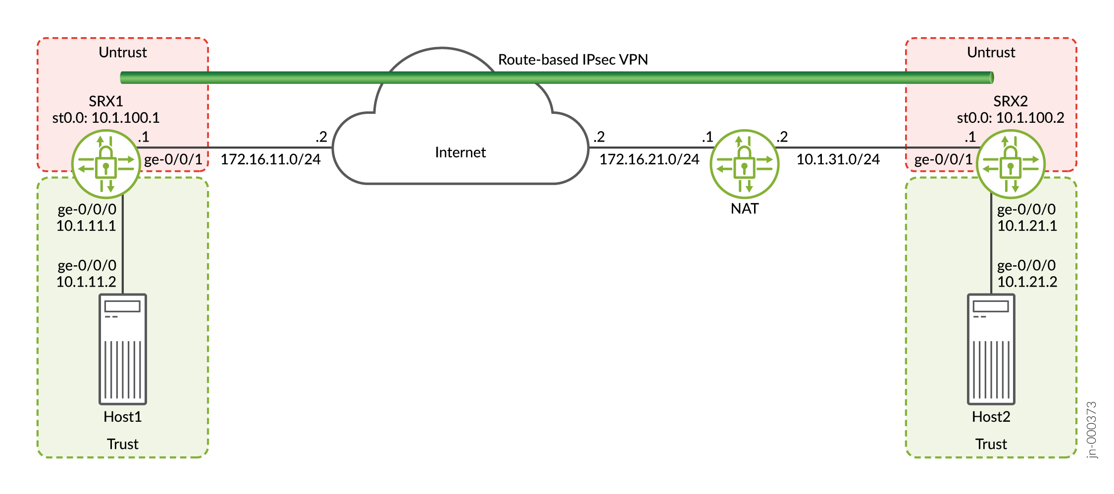
In this example, you configure interfaces, IPsec, and security policies for both an initiator in SRX1 and a responder in SRX2. Then you configure IKE Phase 1 and IPsec Phase 2 parameters.
SRX1 sends packets with the destination address of 172.16.21.1 to establish the VPN. The NAT device translates the destination address to 10.1.31.1.
See Table 1 through Table 3 for specific configuration parameters used for the initiator in the examples.
|
Feature |
Name |
Configuration Parameters |
|---|---|---|
|
Interfaces |
ge-0/0/1 |
172.16.11.1/24 |
|
ge-0/0/0 |
10.1.11.1/24 |
|
|
st0.0 (tunnel interface) |
10.1.100.1/24 |
|
|
Static routes |
10.1.21.0/24 |
The next hop is st0.0. |
|
172.16.21.1/32 |
The next hop is 172.16.11.2. |
|
|
Security zones |
untrust |
|
|
trust |
|
|
|
Security policies |
to-SRX2 |
Permit traffic from 10.1.11.0/24 in the trust zone to 10.1.21.0/24 in the untrust zone. |
|
from-SRX2 |
Permit traffic from 10.1.21.0/24 in the untrust zone to 10.1.11.0/24 in the trust zone. |
|
Feature |
Name |
Configuration Parameters |
|---|---|---|
|
Proposal |
ike_prop |
|
|
Policy |
ike_pol |
|
|
Gateway |
gw1 |
|
|
Feature |
Name |
Configuration Parameters |
|---|---|---|
|
Proposal |
ipsec_prop |
|
|
Policy |
ipsec_pol |
|
|
VPN |
vpn1 |
|
See Table 4 through Table 6 for specific configuration parameters used for the responder in the examples.
|
Feature |
Name |
Configuration Parameters |
|---|---|---|
|
Interfaces |
ge-0/0/1 |
10.1.31.1/24 |
|
ge-0/0/0 |
10.1.21.1/24 |
|
|
st0.0 (tunnel interface) |
10.1.100.2/24 |
|
|
Static routes |
172.16.11.1/32 |
The next hop is 10.1.31.2. |
|
10.1.11.0/24 |
The next hop is st0.0. |
|
|
Security zones |
untrust |
|
|
trust |
|
|
|
Security policies |
to-SRX1 |
Permit traffic from 10.1.21.0/24 in the trust zone to 10.1.11.0/24 in the untrust zone. |
|
from-SRX1 |
Permit traffic from 10.1.11.0/24 in the untrust zone to 10.1.21.0/24 in the trust zone. |
|
Feature |
Name |
Configuration Parameters |
|---|---|---|
|
Proposal |
ike_prop |
|
|
Policy |
ike_pol |
|
|
Gateway |
gw1 |
|
|
Feature |
Name |
Configuration Parameters |
|---|---|---|
|
Proposal |
ipsec_prop |
|
|
Policy |
ipsec_pol |
|
|
VPN |
vpn1 |
|
Configuration
- Configuring Interface, Routing Options, and Security Parameters for SRX1
- Configuring IKE for SRX1
- Configuring IPsec for SRX1
- Configuring Interfaces, Routing Options, and Security Parameters for SRX2
- Configuring IKE for SRX2
- Configuring IPsec for SRX2
- Configuration for the NAT Device
Configuring Interface, Routing Options, and Security Parameters for SRX1
CLI Quick Configuration
To quickly configure this example, copy the following commands, paste them
into a text file, remove any line breaks, change any details necessary to
match your network configuration, copy and paste the commands into the CLI
at the [edit] hierarchy level, and then enter
commit from configuration mode.
set security address-book book1 address Host1 10.1.11.0/24
set security address-book book1 attach zone trust
set security address-book book2 address Host2 10.1.21.0/24
set security address-book book2 attach zone untrust
set security policies from-zone trust to-zone untrust policy to-SRX2 match source-address Host1
set security policies from-zone trust to-zone untrust policy to-SRX2 match destination-address Host2
set security policies from-zone trust to-zone untrust policy to-SRX2 match application any
set security policies from-zone trust to-zone untrust policy to-SRX2 then permit
set security policies from-zone untrust to-zone trust policy from-SRX2 match source-address Host2
set security policies from-zone untrust to-zone trust policy from-SRX2 match destination-address Host1
set security policies from-zone untrust to-zone trust policy from-SRX2 match application any
set security policies from-zone untrust to-zone trust policy from-SRX2 then permit
set security zones security-zone untrust host-inbound-traffic system-services ike
set security zones security-zone untrust host-inbound-traffic system-services ping
set security zones security-zone untrust interfaces st0.0
set security zones security-zone untrust interfaces ge-0/0/1.0
set security zones security-zone trust host-inbound-traffic system-services all
set security zones security-zone trust host-inbound-traffic protocols all
set security zones security-zone trust interfaces ge-0/0/0.0
set interfaces ge-0/0/0 unit 0 family inet address 10.1.11.1/24
set interfaces ge-0/0/1 unit 0 family inet address 172.16.11.1/24
set interfaces st0 unit 0 family inet address 10.1.100.1/24
set routing-options static route 10.1.21.0/24 next-hop st0.0
set routing-options static route 172.16.21.1/32 next-hop 172.16.11.2
Step-by-Step Procedure
The following example requires you to navigate various levels in the configuration hierarchy. For instructions on how to do that, see Using the CLI Editor in Configuration Mode in the CLI User Guide.
To configure interfaces, static routes, and security parameters:
-
Configure the interfaces connected to the Internet, Host1, and the interface used for the VPN.
[edit]
user@SRX1# set interfaces ge-0/0/0 unit 0 family inet address 10.1.11.1/24
user@SRX1# set interfaces ge-0/0/1 unit 0 family inet address 172.16.11.1/24
user@SRX1# set interfaces st0 unit 0 family inet address 10.1.100.1/24
-
Configure static routes for the traffic that will use the VPN and for SRX1 to reach the NAT device.
[edit]
user@SRX1# set routing-options static route 10.1.21.0/24 next-hop st0.0
user@SRX1# set routing-options static route 172.16.21.1/32 next-hop 172.16.11.2
-
Configure the untrust security zone.
[edit]
user@SRX1# set security zones security-zone untrust host-inbound-traffic system-services ike
user@SRX1# set security zones security-zone untrust host-inbound-traffic system-services ping
user@SRX1# set security zones security-zone untrust interfaces st0.0
user@SRX1# set security zones security-zone untrust interfaces ge-0/0/1.0
-
Configure the trust security zone.
[edit]
user@SRX1# set security zones security-zone trust host-inbound-traffic system-services all
user@SRX1# set security zones security-zone trust host-inbound-traffic protocols all
user@SRX1# set security zones security-zone trust interfaces ge-0/0/0.0
-
Configure address books for the networks used in the security policies.
[edit]
user@SRX1# set security address-book book1 address Host1 10.1.11.0/24
user@SRX1# set security address-book book1 attach zone trust
user@SRX1# set security address-book book2 address Host2 10.1.21.0/24
user@SRX1# set security address-book book2 attach zone untrust
-
Create security policies to allow traffic between the hosts.
[edit]
user@SRX1# set security policies from-zone trust to-zone untrust policy to-SRX2 match source-address Host1
user@SRX1# set security policies from-zone trust to-zone untrust policy to-SRX2 match destination-address Host2
user@SRX1# set security policies from-zone trust to-zone untrust policy to-SRX2 match application any
user@SRX1# set security policies from-zone trust to-zone untrust policy to-SRX2 then permit
user@SRX1# set security policies from-zone untrust to-zone trust policy from-SRX2 match source-address Host2
user@SRX1# set security policies from-zone untrust to-zone trust policy from-SRX2 match destination-address Host1
user@SRX1# set security policies from-zone untrust to-zone trust policy from-SRX2 match application any
user@SRX1# set security policies from-zone untrust to-zone trust policy from-SRX2 then permit
Results
From configuration mode, confirm your configuration by entering the
show interfaces, show routing-options,
and
show
                            security
commands.
If the output does not display the intended configuration, repeat the
instructions in this example to correct the configuration.
[edit]
user@SRX1# show interfaces
ge-0/0/0 {
    unit 0 {
        family inet {
            address 10.1.11.1/24;
        }
    }
}
ge-0/0/1 {
    unit 0 {
        family inet {
            address 172.16.11.1/24;
        }
    }
}
st0 {
    unit 0 {
        family inet {
            address 10.1.100.1/24;
        }
    }
}[edit]
user@SRX1# show routing-options
static {
route 10.1.21.0/24 next-hop st0.0;
route 172.16.21.1/32 next-hop 172.16.11.2;
}[edit]
user@SRX1# show security
address-book {
book1 {
address Host1 10.1.11.0/24;
attach {
zone trust;
}
}
book2 {
address Host2 10.1.21.0/24;
attach {
zone untrust;
}
}
}
policies {
from-zone trust to-zone untrust {
policy to-SRX2 {
match {
source-address Host1;
destination-address Host2;
application any;
}
then {
permit;
}
}
}
from-zone untrust to-zone trust {
policy from-SRX2 {
match {
source-address Host2;
destination-address Host1;
application any;
}
then {
permit;
}
}
}
}
zones {
security-zone untrust {
host-inbound-traffic {
system-services {
ike;
ping;
}
}
interfaces {
st0.0;
ge-0/0/1.0;
}
}
security-zone trust {
host-inbound-traffic {
system-services {
all;
}
protocols {
all;
}
}
interfaces {
ge-0/0/0.0;
}
}
}If you are done configuring the device, enter commit from
configuration mode.
Configuring IKE for SRX1
CLI Quick Configuration
To quickly configure this example, copy the following commands, paste them
into a text file, remove any line breaks, change any details necessary to
match your network configuration, copy and paste the commands into the CLI
at the [edit] hierarchy level, and then enter
commit from configuration mode.
set security ike proposal ike_prop authentication-method pre-shared-keys
set security ike proposal ike_prop dh-group group2
set security ike proposal ike_prop authentication-algorithm sha1
set security ike proposal ike_prop encryption-algorithm 3des-cbc
set security ike policy ike_pol mode main
set security ike policy ike_pol proposals ike_prop
set security ike policy ike_pol pre-shared-key ascii-text “$ABC123”
set security ike gateway gw1 ike-policy ike_pol
set security ike gateway gw1 address 172.16.21.1
set security ike gateway gw1 local-identity user-at-hostname "srx1@example.com"
set security ike gateway gw1 remote-identity user-at-hostname "srx2@example.com"
set security ike gateway gw1 external-interface ge-0/0/1.0
Step-by-Step Procedure
The following example requires you to navigate various levels in the configuration hierarchy. For instructions on how to do that, see Using the CLI Editor in Configuration Mode in the CLI User Guide.
To configure IKE:
-
Create an IKE Phase 1 proposal.
[edit]
user@SRX1# set security ike proposal ike_prop authentication-method pre-shared-keys
user@SRX1# set security ike proposal ike_prop dh-group group2
user@SRX1# set security ike proposal ike_prop authentication-algorithm sha1
user@SRX1# set security ike proposal ike_prop encryption-algorithm 3des-cbc
-
Create an IKE Phase 1 policy.
[edit]
user@SRX1# set security ike policy ike_pol mode main
user@SRX1# set security ike policy ike_pol proposals ike_prop
user@SRX1# set security ike policy ike_pol pre-shared-key ascii-text “$ABC123”
-
Configure the IKE Phase 1 gateway parameters. The gateway address should be the IP for the NAT device.
[edit security ike gateway gw1]
user@SRX1# set security ike gateway gw1 ike-policy ike_pol
user@SRX1# set security ike gateway gw1 address 172.16.21.1
user@SRX1# set security ike gateway gw1 local-identity user-at-hostname "srx1@example.com"
user@SRX1# set security ike gateway gw1 remote-identity user-at-hostname "srx2@example.com"
user@SRX1# set security ike gateway gw1 external-interface ge-0/0/1.0
Results
From configuration mode, confirm your configuration by entering the
show security ike command. If the output does not
display the intended configuration, repeat the instructions in this example
to correct the configuration.
[edit]
user@SRX1# show security ike
proposal ike_prop {
    authentication-method pre-shared-keys;
    dh-group group2;
    authentication-algorithm sha1;
    encryption-algorithm 3des-cbc;
}
policy ike_pol {
    mode main;
    proposals ike_prop;
    pre-shared-key ascii-text “$9$xPn7-VwsgaJUHqp01IcSs2g”; ## SECRET-DATA
}
gateway gw1 {
    ike-policy ike_pol;
    address 172.16.21.1;
    local-identity user-at-hostname "srx1@example.com";
    remote-identity user-at-hostname "srx2@example.com";
    external-interface ge-0/0/1.0;
}
If you are done configuring the device, enter commit from
configuration mode.
Configuring IPsec for SRX1
CLI Quick Configuration
To quickly configure this example, copy the following commands, paste them
into a text file, remove any line breaks, change any details necessary to
match your network configuration, copy and paste the commands into the CLI
at the [edit] hierarchy level, and then enter
commit from configuration mode.
set security ipsec proposal ipsec_prop protocol esp
set security ipsec proposal ipsec_prop authentication-algorithm hmac-sha1-96
set security ipsec proposal ipsec_prop encryption-algorithm 3des-cbc
set security ipsec policy ipsec_pol perfect-forward-secrecy keys group2
set security ipsec policy ipsec_pol proposals ipsec_prop
set security ipsec vpn vpn1 bind-interface st0.0
set security ipsec vpn vpn1 ike gateway gw1
set security ipsec vpn vpn1 ike ipsec-policy ipsec_pol
set security ipsec vpn vpn1 establish-tunnels immediately
Step-by-Step Procedure
The following example requires you to navigate various levels in the configuration hierarchy. For instructions on how to do that, see Using the CLI Editor in Configuration Mode in the CLI User Guide.
To configure IPsec:
-
Create an IPsec Phase 2 proposal.
[edit]
user@SRX1# set security ipsec proposal ipsec_prop protocol esp
user@SRX1# set security ipsec proposal ipsec_prop authentication-algorithm hmac-sha1-96
user@SRX1# set security ipsec proposal ipsec_prop encryption-algorithm 3des-cbc
-
Create the IPsec Phase 2 policy.
[edit]
user@SRX1# set security ipsec policy ipsec_pol perfect-forward-secrecy keys group2
user@SRX1# set security ipsec policy ipsec_pol proposals ipsec_prop
-
Configure the IPsec VPN parameters.
[edit]
user@SRX1# set security ipsec vpn vpn1 bind-interface st0.0
user@SRX1# set security ipsec vpn vpn1 ike gateway gw1
user@SRX1# set security ipsec vpn vpn1 ike ipsec-policy ipsec_pol
user@SRX1# set security ipsec vpn vpn1 establish-tunnels immediately
Results
From configuration mode, confirm your configuration by entering the
show security ipsec command. If the output does not
display the intended configuration, repeat the instructions in this example
to correct the configuration.
[edit]
user@SRX1# show security ipsec
proposal ipsec_prop {
    protocol esp;
    authentication-algorithm hmac-sha1-96;
    encryption-algorithm 3des-cbc;
}
policy ipsec_pol {
    perfect-forward-secrecy {
        keys group2;
    }
    proposals ipsec_prop;
}
vpn vpn1 {
    bind-interface st0.0;
    ike {
        gateway gw1;
        ipsec-policy ipsec_pol;
    }
    establish-tunnels immediately;
}
If you are done configuring the device, enter commit from
configuration mode.
Configuring Interfaces, Routing Options, and Security Parameters for SRX2
CLI Quick Configuration
To quickly configure this example, copy the following commands, paste them
into a text file, remove any line breaks, change any details necessary to
match your network configuration, copy and paste the commands into the CLI
at the [edit] hierarchy level, and then enter
commit from configuration mode.
set security address-book book1 address Host2 10.1.21.0/24
set security address-book book1 attach zone trust
set security address-book book2 address Host1 10.1.11.0/24
set security address-book book2 attach zone untrust
set security policies from-zone trust to-zone untrust policy to-SRX1 match source-address Host2
set security policies from-zone trust to-zone untrust policy to-SRX1 match destination-address Host1
set security policies from-zone trust to-zone untrust policy to-SRX1 match application any
set security policies from-zone trust to-zone untrust policy to-SRX1 then permit
set security policies from-zone untrust to-zone trust policy from-SRX1 match source-address Host1
set security policies from-zone untrust to-zone trust policy from-SRX1 match destination-address Host2
set security policies from-zone untrust to-zone trust policy from-SRX1 match application any
set security policies from-zone untrust to-zone trust policy from-SRX1 then permit
set security zones security-zone untrust host-inbound-traffic system-services ike
set security zones security-zone untrust host-inbound-traffic system-services ping
set security zones security-zone untrust interfaces ge-0/0/1.0
set security zones security-zone untrust interfaces st0.0
set security zones security-zone trust host-inbound-traffic system-services all
set security zones security-zone trust host-inbound-traffic protocols all
set security zones security-zone trust interfaces ge-0/0/0.0
set interfaces ge-0/0/0 unit 0 family inet address 10.1.21.1/24
set interfaces ge-0/0/1 unit 0 family inet address 10.1.31.1/24
set interfaces st0 unit 0 family inet address 10.1.100.2/24
set routing-options static route 172.16.11.1/32 next-hop 10.1.31.2
set routing-options static route 10.1.11.0/24 next-hop st0.0
Step-by-Step Procedure
The following example requires you to navigate various levels in the configuration hierarchy. For instructions on how to do that, see Using the CLI Editor in Configuration Mode in the CLI User Guide.
To configure interfaces, static routes, and security parameters:
-
Configure the interfaces connected to the Internet, Host2, and the interface used for the VPN.
[edit]
user@SRX2# set interfaces ge-0/0/0 unit 0 family inet address 10.1.21.1/24
user@SRX2# set interfaces ge-0/0/1 unit 0 family inet address 10.1.31.1/24
user@SRX2# set interfaces st0 unit 0 family inet address 10.1.100.2/24
-
Configure static routes for the traffic that will use the VPN and for SRX2 to reach SRX1.
[edit]
user@SRX2# set routing-options static route 172.16.11.1/32 next-hop 10.1.31.2
user@SRX2# set routing-options static route 10.1.11.0/24 next-hop st0.0
-
Configure the untrust security zone.
[edit]
user@SRX2# set security zones security-zone untrust host-inbound-traffic system-services ike
user@SRX2# set security zones security-zone untrust host-inbound-traffic system-services ping
user@SRX2# set security zones security-zone untrust interfaces ge-0/0/1.0
user@SRX2# set security zones security-zone untrust interfaces st0.0
-
Configure the trust security zone.
[edit]
user@SRX2# set security zones security-zone trust host-inbound-traffic system-services all
user@SRX2# set security zones security-zone trust host-inbound-traffic protocols all
user@SRX2# set security zones security-zone trust interfaces ge-0/0/0.0
-
Configure address books for the networks used in the security policies.
[edit]
user@SRX2# set security address-book book1 address Host2 10.1.21.0/24
user@SRX2# set security address-book book1 attach zone trust
user@SRX2# set security address-book book2 address Host1 10.1.11.0/24
user@SRX2# set security address-book book2 attach zone untrust
-
Create security policies to allow traffic between the hosts.
[edit]
user@SRX2# set security policies from-zone trust to-zone untrust policy to-SRX1 match source-address Host2
user@SRX2# set security policies from-zone trust to-zone untrust policy to-SRX1 match destination-address Host1
user@SRX2# set security policies from-zone trust to-zone untrust policy to-SRX1 match application any
user@SRX2# set security policies from-zone trust to-zone untrust policy to-SRX1 then permit
user@SRX2# set security policies from-zone untrust to-zone trust policy from-SRX1 match source-address Host1
user@SRX2# set security policies from-zone untrust to-zone trust policy from-SRX1 match destination-address Host2
user@SRX2# set security policies from-zone untrust to-zone trust policy from-SRX1 match application any
user@SRX2# set security policies from-zone untrust to-zone trust policy from-SRX1 then permit
Results
From configuration mode, confirm your configuration by entering the
show interfaces, show routing-options,
and
show
                            security
commands. If the output does not display the intended configuration, repeat
the instructions in this example to correct the configuration.
[edit]
user@SRX2# show interfaces
ge-0/0/0 {
    unit 0 {
        family inet {
            address 10.1.21.1/24;
        }
    }
}
ge-0/0/1 {
    unit 0 {
        family inet {
            address 10.1.31.1/24;
        }
    }
}
st0 {
    unit 0 {
        family inet {
            address 10.1.100.2/24;
        }
    }
}[edit]
user@SRX2# show routing-options
static {
route 172.16.11.1/32 next-hop 10.1.31.2;
route 10.1.11.0/24 next-hop st0.0;
}[edit]
user@SRX2# show security
address-book {
book1 {
address Host2 10.1.21.0/24;
attach {
zone trust;
}
}
book2 {
address Host1 10.1.11.0/24;
attach {
zone untrust;
}
}
}
policies {
from-zone trust to-zone untrust {
policy to-SRX1 {
match {
source-address Host2;
destination-address Host1;
application any;
}
then {
permit;
}
}
}
from-zone untrust to-zone trust {
policy from-SRX1 {
match {
source-address Host1;
destination-address Host2;
application any;
}
then {
permit;
}
}
}
}
zones {
security-zone untrust {
host-inbound-traffic {
system-services {
ike;
ping;
}
}
interfaces {
ge-0/0/1.0;
st0.0;
}
}
security-zone trust {
host-inbound-traffic {
system-services {
all;
}
protocols {
all;
}
}
interfaces {
ge-0/0/0.0;
}
}
}If you are done configuring the device, enter commit from
configuration mode.
Configuring IKE for SRX2
CLI Quick Configuration
To quickly configure this example, copy the following commands, paste them
into a text file, remove any line breaks, change any details necessary to
match your network configuration, copy and paste the commands into the CLI
at the [edit] hierarchy level, and then enter
commit from configuration mode.
set security ike proposal ike_prop authentication-method pre-shared-keys
set security ike proposal ike_prop dh-group group2
set security ike proposal ike_prop authentication-algorithm sha1
set security ike proposal ike_prop encryption-algorithm 3des-cbc
set security ike policy ike_pol mode main
set security ike policy ike_pol proposals ike_prop
set security ike policy ike_pol pre-shared-key ascii-text “$ABC123”
set security ike gateway gw1 ike-policy ike_pol
set security ike gateway gw1 address 172.16.11.1
set security ike gateway gw1 local-identity user-at-hostname "srx2@example.com"
set security ike gateway gw1 remote-identity user-at-hostname "srx1@example.com"
set security ike gateway gw1 external-interface ge-0/0/1.0
Step-by-Step Procedure
The following example requires you to navigate various levels in the configuration hierarchy. For instructions on how to do that, see Using the CLI Editor in Configuration Mode in the CLI User Guide.
To configure IKE:
-
Create an IKE Phase 1 proposal.
[edit]
user@SRX2# set security ike proposal ike_prop authentication-method pre-shared-keys
user@SRX2# set security ike proposal ike_prop dh-group group2
user@SRX2# set security ike proposal ike_prop authentication-algorithm sha1
user@SRX2# set security ike proposal ike_prop encryption-algorithm 3des-cbc
-
Create an IKE Phase 1 policy.
[edit]
user@SRX2# set security ike policy ike_pol mode main
user@SRX2# set security ike policy ike_pol proposals ike_prop
user@SRX2# set security ike policy ike_pol pre-shared-key ascii-text “$ABC123”
-
Configure the IKE Phase 1 gateway parameters. The gateway address should be the IP for SRX1.
[edit]
user@SRX2# set security ike gateway gw1 ike-policy ike_pol
user@SRX2# set security ike gateway gw1 address 172.16.11.1
user@SRX2# set security ike gateway gw1 local-identity user-at-hostname "srx2@example.com"
user@SRX2# set security ike gateway gw1 remote-identity user-at-hostname "srx1@example.com"
user@SRX2# set security ike gateway gw1 external-interface ge-0/0/1.0
Results
From configuration mode, confirm your configuration by entering the
show security ike command. If the output does not
display the intended configuration, repeat the instructions in this example
to correct the configuration.
[edit]
user@SRX2# show security ike
proposal ike_prop {
    authentication-method pre-shared-keys;
    dh-group group2;
    authentication-algorithm sha1;
    encryption-algorithm 3des-cbc;
}
policy ike_pol {
    mode main;
    proposals ike_prop;
    pre-shared-key ascii-text "$9$mP5QF3/At0IE-VsYoa36/"; ## SECRET-DATA
}
gateway gw1 {
    ike-policy ike_pol;
    address 172.16.11.1;
    local-identity user-at-hostname "srx2@example.com";
    remote-identity user-at-hostname "srx1@example.com";
    external-interface ge-0/0/1.0;
}
If you are done configuring the device, enter commit from
configuration mode.
Configuring IPsec for SRX2
CLI Quick Configuration
To quickly configure this example, copy the following commands, paste them
into a text file, remove any line breaks, change any details necessary to
match your network configuration, copy and paste the commands into the CLI
at the [edit] hierarchy level, and then enter
commit from configuration mode.
set security ipsec proposal ipsec_prop protocol esp
set security ipsec proposal ipsec_prop authentication-algorithm hmac-sha1-96
set security ipsec proposal ipsec_prop encryption-algorithm 3des-cbc
set security ipsec policy ipsec_pol perfect-forward-secrecy keys group2
set security ipsec policy ipsec_pol proposals ipsec_prop
set security ipsec vpn vpn1 bind-interface st0.0
set security ipsec vpn vpn1 ike gateway gw1
set security ipsec vpn vpn1 ike ipsec-policy ipsec_pol
set security ipsec vpn vpn1 establish-tunnels immediately
Step-by-Step Procedure
The following example requires you to navigate various levels in the configuration hierarchy. For instructions on how to do that, see Using the CLI Editor in Configuration Mode in the CLI User Guide.
To configure IPsec:
-
Create an IPsec Phase 2 proposal.
[edit]
user@SRX2# set security ipsec proposal ipsec_prop protocol esp
user@SRX2# set security ipsec proposal ipsec_prop authentication-algorithm hmac-sha1-96
user@SRX2# set security ipsec proposal ipsec_prop encryption-algorithm 3des-cbc
-
Create the IPsec Phase 2 policy.
[edit]
user@SRX2# set security ipsec policy ipsec_pol perfect-forward-secrecy keys group2
user@SRX2# set security ipsec policy ipsec_pol proposals ipsec_prop
-
Configure the IPsec VPN parameters.
[edit]
user@SRX2# set security ipsec vpn vpn1 bind-interface st0.0
user@SRX2# set security ipsec vpn vpn1 ike gateway gw1
user@SRX2# set security ipsec vpn vpn1 ike ipsec-policy ipsec_pol
user@SRX2# set security ipsec vpn vpn1 establish-tunnels immediately
Results
From configuration mode, confirm your configuration by entering the
show security ipsec command. If the output does not
display the intended configuration, repeat the instructions in this example
to correct the configuration.
[edit]
user@SRX2# show security ipsec
proposal ipsec_prop {
    protocol esp;
    authentication-algorithm hmac-sha1-96;
    encryption-algorithm 3des-cbc;
}
policy ipsec_pol {
    perfect-forward-secrecy {
        keys group2;
    }
    proposals ipsec_prop;
}
vpn vpn1 {
    bind-interface st0.0;
    ike {
        gateway gw1;
        ipsec-policy ipsec_pol;
    }
    establish-tunnels immediately;
}
If you are done configuring the device, enter commit from
configuration mode.
Configuration for the NAT Device
CLI Quick Configuration
Static NAT is used in the example. Static NAT is bidirectional which means that traffic from 10.1.31.1 to 172.16.11.1 will also use the same NAT configuration.
To quickly configure this example, copy the following commands, paste them
into a text file, remove any line breaks, change any details necessary to
match your network configuration, copy and paste the commands into the CLI
at the [edit] hierarchy level, and then enter
commit from configuration mode.
set security nat static rule-set rule1 from zone untrust
set security nat static rule-set rule1 rule ipsec match source-address 172.16.11.1/32
set security nat static rule-set rule1 rule ipsec match destination-address 172.16.21.1/32
set security nat static rule-set rule1 rule ipsec then static-nat prefix 10.1.31.1/32
set security policies from-zone trust to-zone untrust policy allow-out match source-address any
set security policies from-zone trust to-zone untrust policy allow-out match destination-address any
set security policies from-zone trust to-zone untrust policy allow-out match application any
set security policies from-zone trust to-zone untrust policy allow-out then permit
set security policies from-zone untrust to-zone trust policy allow-out-in match source-address any
set security policies from-zone untrust to-zone trust policy allow-out-in match destination-address any
set security policies from-zone untrust to-zone trust policy allow-out-in match application any
set security policies from-zone untrust to-zone trust policy allow-out-in then permit
set security zones security-zone trust host-inbound-traffic system-services ping
set security zones security-zone trust interfaces ge-0/0/1.0
set security zones security-zone untrust host-inbound-traffic system-services ping
set security zones security-zone untrust interfaces ge-0/0/0.0
set interfaces ge-0/0/0 unit 0 family inet address 172.16.21.1/24
set interfaces ge-0/0/1 unit 0 family inet address 10.1.31.2/24
set routing-options static route 172.16.11.0/24 next-hop 172.16.21.2
Verification
To confirm that the configuration is working properly, perform these tasks:
- Verifying the IKE Phase 1 Status on SRX1
- Verifying IPsec Security Associations on SRX1
- Verifying the IKE Phase 1 Status on SRX2
- Verifying IPsec Security Associations on SRX2
- Verifying Host-to-Host Reachability
Verifying the IKE Phase 1 Status on SRX1
Purpose
Verify the IKE Phase 1 status.
Action
From operational mode, enter the show security ike security-associations command. For a more detailed output, use the show security ike security-associations detail command.
user@SRX1> show security ike security-associations
Index   State  Initiator cookie  Responder cookie  Mode           Remote Address
302301  UP     84e8fc61d0750278  ea9a07ef032805b6  Main           172.16.21.1
user@SRX1> show security ike security-associations detail
IKE peer 172.16.21.1, Index 302301, Gateway Name: gw1
  Role: Initiator, State: UP
  Initiator cookie: 84e8fc61d0750278, Responder cookie: ea9a07ef032805b6
  Exchange type: Main, Authentication method: Pre-shared-keys
  Local: 172.16.11.1:4500, Remote: 172.16.21.1:4500
  Lifetime: Expires in 19657 seconds
  Reauth Lifetime: Disabled
  IKE Fragmentation: Disabled, Size: 0
  Remote Access Client Info: Unknown Client
  Peer ike-id: srx2@example.com
  AAA assigned IP: 0.0.0.0
  Algorithms:
   Authentication        : hmac-sha1-96
   Encryption            : 3des-cbc
   Pseudo random function: hmac-sha1
   Diffie-Hellman group  : DH-group-2
  Traffic statistics:
   Input  bytes  :                 1780
   Output bytes  :                 2352
   Input  packets:                    7
   Output packets:                   14
   Input  fragmentated packets:       0
   Output fragmentated packets:       0
  IPSec security associations: 4 created, 0 deleted
  Phase 2 negotiations in progress: 1

    Negotiation type: Quick mode, Role: Initiator, Message ID: 0
    Local: 172.16.11.1:4500, Remote: 172.16.21.1:4500
    Local identity: srx1@example.com
    Remote identity: srx2@example.com
    Flags: IKE SA is created
Meaning
The show security ike security-associations command lists
all active IKE Phase 1 SAs. If no SAs are listed, there was a problem with
Phase 1 establishment. Check the IKE policy parameters and external
interface settings in your configuration.
If SAs are listed, review the following information:
-
Index—This value is unique for each IKE SA, which you can use in the
show security ike security-associations index
                                    detail
command to get more information about the SA. -
Remote address—Verify that the remote IP address is correct and that port 4500 is being used for peer-to-peer communication. Remember that NAT-T encapsulates both IKE and ESP traffic within UDP with port 4500.
-
Role initiator state
-
Up—The Phase 1 SA is established.
-
Down—There was a problem establishing the Phase 1 SA.
-
Both peers in the IPsec SA pair are using port 4500.
-
Peer IKE ID—Verify the remote address is correct.
-
Local identity and remote identity—Verify these are correct.
-
-
Mode—Verify that the correct mode is being used.
Verify that the following are correct in your configuration:
-
External interfaces (the interface must be the one that receives IKE packets)
-
IKE policy parameters
-
Preshared key information
-
Phase 1 proposal parameters (must match on both peers)
The show security ike security-associations command lists
additional information about security associations:
-
Authentication and encryption algorithms used
-
Phase 1 lifetime
-
Traffic statistics (can be used to verify that traffic is flowing properly in both directions)
-
Role information
Troubleshooting is best performed on the peer using the responder role.
-
Initiator and responder information
-
Number of IPsec SAs created
-
Number of Phase 2 negotiations in progress
Verifying IPsec Security Associations on SRX1
Purpose
Verify the IPsec status.
Action
From operational mode, enter the show security ipsec security-associations command. For a more detailed output, use the show security ipsec security-associations detail command.
user@SRX1> show security ipsec security-associations
  Total active tunnels: 1     Total Ipsec sas: 1
  ID    Algorithm       SPI      Life:sec/kb  Mon lsys Port  Gateway
  <131073 ESP:3des/sha1   fc5dbac4 2160/ unlim  -   root 4500  172.16.21.1
  >131073 ESP:3des/sha1   45fed9d8 2160/ unlim  -   root 4500  172.16.21.1
user@SRX1> show security ipsec security-associations detail
ID: 131073 Virtual-system: root, VPN Name: vpn1
  Local Gateway: 172.16.11.1, Remote Gateway: 172.16.21.1
  Local Identity: ipv4_subnet(any:0,[0..7]=0.0.0.0/0)
  Remote Identity: ipv4_subnet(any:0,[0..7]=0.0.0.0/0)
  Version: IKEv1
  DF-bit: clear, Copy-Outer-DSCP Disabled, Bind-interface: st0.0
  Port: 4500, Nego#: 7, Fail#: 0, Def-Del#: 0 Flag: 0x600a29
  Multi-sa, Configured SAs# 1, Negotiated SAs#: 1
  Tunnel events:
    Fri Jul 22 2022 11:07:40 -0700: IPSec SA rekey successfully completed (3 times)
    Fri Jul 22 2022 08:38:41 -0700: IPSec SA negotiation successfully completed (1 times)
    Fri Jul 22 2022 08:38:41 -0700: User cleared IPSec SA from CLI (1 times)
    Fri Jul 22 2022 08:38:41 -0700: IKE SA negotiation successfully completed (3 times)
    Fri Jul 22 2022 08:38:26 -0700: IPSec SA negotiation successfully completed (1 times)
    Fri Jul 22 2022 08:38:26 -0700: User cleared IPSec SA from CLI (1 times)
    Fri Jul 22 2022 08:38:25 -0700: IPSec SA negotiation successfully completed (1 times)
    Fri Jul 22 2022 08:38:24 -0700: User cleared IPSec SA from CLI (1 times)
    Fri Jul 22 2022 08:37:37 -0700: IPSec SA negotiation successfully completed (1 times)
  Direction: inbound, SPI: fc5dbac4, AUX-SPI: 0
                              , VPN Monitoring: -
    Hard lifetime: Expires in 2153 seconds
    Lifesize Remaining:  Unlimited
    Soft lifetime: Expires in 1532 seconds
    Mode: Tunnel(0 0), Type: dynamic, State: installed
    Protocol: ESP, Authentication: hmac-sha1-96, Encryption: 3des-cbc
    Anti-replay service: counter-based enabled, Replay window size: 64
  Direction: outbound, SPI: 45fed9d8, AUX-SPI: 0
                              , VPN Monitoring: -
    Hard lifetime: Expires in 2153 seconds
    Lifesize Remaining:  Unlimited
    Soft lifetime: Expires in 1532 seconds
    Mode: Tunnel(0 0), Type: dynamic, State: installed
    Protocol: ESP, Authentication: hmac-sha1-96, Encryption: 3des-cbc
    Anti-replay service: counter-based enabled, Replay window size: 64
Meaning
The output from the show security ipsec
security-associations command lists the following
information:
-
The remote gateway has an address of 172.16.21.1.
-
Both peers in the IPsec SA pair are using port 4500.
-
The SPIs, lifetime (in seconds), and usage limits (or lifesize in KB) are shown for both directions. The 2160/ unlim value indicates that the Phase 2 lifetime expires in 2160 seconds, and that no lifesize has been specified, which indicates that it is unlimited. Phase 2 lifetime can differ from Phase 1 lifetime, as Phase 2 is not dependent on Phase 1 after the VPN is up.
-
VPN monitoring is not enabled for this SA, as indicated by a hyphen in the Mon column. If VPN monitoring is enabled, U indicates that monitoring is up, and D indicates that monitoring is down.
-
The virtual system (vsys) is the root system, and it always lists 0.
Verifying the IKE Phase 1 Status on SRX2
Purpose
Verify the IKE Phase 1 status.
Action
From operational mode, enter the show security ike security-associations command. For a more detailed output, use the show security ike security-associations detail command.
user@SRX2> show security ike security-associations
Index   State  Initiator cookie  Responder cookie  Mode           Remote Address
5567091 UP     84e8fc61d0750278  ea9a07ef032805b6  Main           172.16.11.1
user@SRX2> show security ike security-associations detail
IKE peer 172.16.11.1, Index 5567091, Gateway Name: gw1
  Role: Responder, State: UP
  Initiator cookie: 84e8fc61d0750278, Responder cookie: ea9a07ef032805b6
  Exchange type: Main, Authentication method: Pre-shared-keys
  Local: 10.1.31.1:4500, Remote: 172.16.11.1:4500
  Lifetime: Expires in 18028 seconds
  Reauth Lifetime: Disabled
  IKE Fragmentation: Disabled, Size: 0
  Remote Access Client Info: Unknown Client
  Peer ike-id: srx1@example.com
  AAA assigned IP: 0.0.0.0
  Algorithms:
   Authentication        : hmac-sha1-96
   Encryption            : 3des-cbc
   Pseudo random function: hmac-sha1
   Diffie-Hellman group  : DH-group-2
  Traffic statistics:
   Input  bytes  :                 2352
   Output bytes  :                 1780
   Input  packets:                   14
   Output packets:                    7
   Input  fragmentated packets:       0
   Output fragmentated packets:       0
  IPSec security associations: 4 created, 3 deleted
  Phase 2 negotiations in progress: 1

    Negotiation type: Quick mode, Role: Responder, Message ID: 0
    Local: 10.1.31.1:4500, Remote: 172.16.11.1:4500
    Local identity: srx2@example.com
    Remote identity: srx1@example.com
    Flags: IKE SA is created
Meaning
The show security ike security-associations command lists
all active IKE Phase 1 SAs. If no SAs are listed, there was a problem with
Phase 1 establishment. Check the IKE policy parameters and external
interface settings in your configuration.
If SAs are listed, review the following information:
-
Index—This value is unique for each IKE SA, which you can use in the
show security ike security-associations
                                    detail
command to get more information about the SA. -
Remote address—Verify that the remote IP address is correct and that port 4500 is being used for peer-to-peer communication.
-
Role responder state
-
Up—The Phase 1 SA has been established.
-
Down—There was a problem establishing the Phase 1 SA.
-
Peer IKE ID—Verify the address is correct.
-
Local identity and remote identity—Verify these addresses are correct.
-
-
Mode—Verify that the correct mode is being used.
Verify that the following are correct in your configuration:
-
External interfaces (the interface must be the one that receives IKE packets)
-
IKE policy parameters
-
Preshared key information
-
Phase 1 proposal parameters (must match on both peers)
The show security ike security-associations command lists
additional information about security associations:
-
Authentication and encryption algorithms used
-
Phase 1 lifetime
-
Traffic statistics (can be used to verify that traffic is flowing properly in both directions)
-
Role information
Troubleshooting is best performed on the peer using the responder role.
-
Initiator and responder information
-
Number of IPsec SAs created
-
Number of Phase 2 negotiations in progress
Verifying IPsec Security Associations on SRX2
Purpose
Verify the IPsec status.
Action
From operational mode, enter the show security ipsec security-associations command. For a more detailed output, use the show security ipsec security-associations detail command.
user@SRX2> show security ipsec security-associations
  Total active tunnels: 1     Total Ipsec sas: 1
  ID    Algorithm       SPI      Life:sec/kb  Mon lsys Port  Gateway
  <131073 ESP:3des/sha1   45fed9d8 1526/ unlim  -   root 4500  172.16.11.1
  >131073 ESP:3des/sha1   fc5dbac4 1526/ unlim  -   root 4500  172.16.11.1
user@SRX2> show security ipsec security-associations detail
ID: 131073 Virtual-system: root, VPN Name: vpn1
  Local Gateway: 10.1.31.1, Remote Gateway: 172.16.11.1
  Local Identity: ipv4_subnet(any:0,[0..7]=0.0.0.0/0)
  Remote Identity: ipv4_subnet(any:0,[0..7]=0.0.0.0/0)
  Version: IKEv1
  DF-bit: clear, Copy-Outer-DSCP Disabled, Bind-interface: st0.0
  Port: 4500, Nego#: 25, Fail#: 0, Def-Del#: 0 Flag: 0x600a29
  Multi-sa, Configured SAs# 1, Negotiated SAs#: 1
  Tunnel events:
    Fri Jul 22 2022 11:07:40 -0700: IPSec SA negotiation successfully completed (4 times)
    Fri Jul 22 2022 08:38:41 -0700: Initial-Contact received from peer. Stale IKE/IPSec SAs cleared (1 times)
    Fri Jul 22 2022 08:38:41 -0700: IKE SA negotiation successfully completed (5 times)
    Fri Jul 22 2022 08:38:26 -0700: IPSec SA negotiation successfully completed (1 times)
    Fri Jul 22 2022 08:38:26 -0700: IPSec SA delete payload received from peer, corresponding IPSec SAs cleared (1 times)
    Fri Jul 22 2022 08:38:25 -0700: IPSec SA negotiation successfully completed (1 times)
    Fri Jul 22 2022 08:38:25 -0700: Initial-Contact received from peer. Stale IKE/IPSec SAs cleared (1 times)
    Fri Jul 22 2022 08:37:37 -0700: IPSec SA negotiation successfully completed (1 times)
    Fri Jul 22 2022 08:37:37 -0700: IPSec SA delete payload received from peer, corresponding IPSec SAs cleared (1 times)
    Thu Jul 21 2022 17:57:09 -0700: Peer's IKE-ID validation failed during negotiation (1 times)
    Thu Jul 21 2022 17:49:30 -0700: IKE SA negotiation successfully completed (4 times)
  Direction: inbound, SPI: 45fed9d8, AUX-SPI: 0
                              , VPN Monitoring: -
    Hard lifetime: Expires in 1461 seconds
    Lifesize Remaining:  Unlimited
    Soft lifetime: Expires in 885 seconds
    Mode: Tunnel(0 0), Type: dynamic, State: installed
    Protocol: ESP, Authentication: hmac-sha1-96, Encryption: 3des-cbc
    Anti-replay service: counter-based enabled, Replay window size: 64
  Direction: outbound, SPI: fc5dbac4, AUX-SPI: 0
                              , VPN Monitoring: -
    Hard lifetime: Expires in 1461 seconds
    Lifesize Remaining:  Unlimited
    Soft lifetime: Expires in 885 seconds
    Mode: Tunnel(0 0), Type: dynamic, State: installed
    Protocol: ESP, Authentication: hmac-sha1-96, Encryption: 3des-cbc
    Anti-replay service: counter-based enabled, Replay window size: 64
Meaning
The output from the show security ipsec
security-associations command lists the following
information:
-
The remote gateway has an ip address of 172.16.11.1.
-
Both peers in the IPsec SA pair are using port 4500.
-
The SPIs, lifetime (in seconds), and usage limits (or lifesize in KB) are shown for both directions. The 1562/ unlim value indicates that the Phase 2 lifetime expires in 1562 seconds, and that no lifesize has been specified, which indicates that it is unlimited. Phase 2 lifetime can differ from Phase 1 lifetime, as Phase 2 is not dependent on Phase 1 after the VPN is up.
-
VPN monitoring is not enabled for this SA, as indicated by a hyphen in the Mon column. If VPN monitoring is enabled, U indicates that monitoring is up, and D indicates that monitoring is down.
-
The virtual system (vsys) is the root system, and it always lists 0.
The output from the show security ipsec security-associations index
index_iddetail command lists the
following information:
-
The local identity and remote identity make up the proxy ID for the SA.
A proxy ID mismatch is one of the most common causes for a Phase 2 failure. If no IPsec SA is listed, confirm that Phase 2 proposals, including the proxy ID settings, are correct for both peers. For route-based VPNs, the default proxy ID is local=0.0.0.0/0, remote=0.0.0.0/0, and service=any. Issues can occur with multiple route-based VPNs from the same peer IP. In this case, a unique proxy ID for each IPsec SA must be specified. For some third-party vendors, the proxy ID must be manually entered to match.
-
Another common reason for Phase 2 failure is not specifying the ST interface binding. If IPsec cannot complete, check the kmd log or set trace options.
Verifying Host-to-Host Reachability
Purpose
Verify Host1 can reach Host2.
Action
From Host1 ping Host2. To verify the traffic is using the VPN, use the
command show security ipsec statistics on SRX1. Clear the
statistics by using the command clear security ipsec
statistics before running the ping command.
user@Host1> ping 10.1.21.2 count 10 rapid
PING 10.1.21.2 (10.1.21.2): 56 data bytes
!!!!!!!!!!
--- 10.1.21.2 ping statistics ---
10 packets transmitted, 10 packets received, 0% packet loss
round-trip min/avg/max/stddev = 3.437/4.270/7.637/1.158 ms
user@SRX1> show security ipsec statistics
ESP Statistics:
  Encrypted bytes:             1360
  Decrypted bytes:              840
  Encrypted packets:             10
  Decrypted packets:             10
AH Statistics:
  Input bytes:                    0
  Output bytes:                   0
  Input packets:                  0
  Output packets:                 0
Errors:
  AH authentication failures: 0, Replay errors: 0
  ESP authentication failures: 0, ESP decryption failures: 0
  Bad headers: 0, Bad trailers: 0
Meaning
The outputs show Host1 can ping Host2 and that the traffic is using the VPN.
Example: Configuring NAT-T with Dynamic Endpoint VPN
This example shows how to configure a route-based VPN where the IKEv2 initiator is a dynamic endpoint behind a NAT device.
Requirements
This example uses the following hardware and software components:
Two firewalls configured in a chassis cluster
One firewall providing NAT
One firewall providing branch office network access
Junos OS Release that supports IKEv2 NAT-T
Overview
In this example, an IPsec VPN is configured between the branch office (IKEv2 initiator) and headquarters (IKEv2 responder) to secure network traffic between the two locations. The branch office is located behind the NAT device. The branch office address is assigned dynamically and is unknown to the responder. The initiator is configured with the remote identity of the responder for tunnel negotiation. This configuration establishes a dynamic endpoint VPN between the peers across the NAT device.
Figure 2 shows an example of a topology with NAT-Traversal (NAT-T) and dynamic endpoint VPN.
In this example, the initiator’s IP address, 192.179.100.50, which has been dynamically assigned to the device, is hidden by the NAT device and translated to 100.10.1.253.
The following configuration options apply in this example:
The local identity configured on the initiator must match the remote gateway identity configured on the responder.
Phase 1 and Phase 2 options must match between the initiator and responder.
In this example, the default security policy that permits all traffic is used for all devices. More restrictive security policies should be configured for production environments. See Security Policies Overview.
Configuration
- Configuring the Branch Office Device (IKEv2 Initiator)
- Configuring the NAT Device
- Configuring the Headquarters Device (IKEv2 Responder)
Configuring the Branch Office Device (IKEv2 Initiator)
CLI Quick Configuration
To quickly configure this example, copy the
following commands, paste them into a text file, remove any line breaks,
change any details necessary to match your network configuration,
copy and paste the commands into the CLI at the [edit] hierarchy
level, and then enter commit from configuration mode.
set interfaces ge-0/0/1 unit 0 family inet address 192.179.100.50/24
set interfaces ge-0/0/2 unit 0 family inet address 192.179.2.20/24
set interfaces st0 unit 0 family inet address 172.168.100.1/16
set routing-options static route 192.179.1.0/24 next-hop st0.0
set security zones security-zone trust host-inbound-traffic system-services all
set security zones security-zone trust host-inbound-traffic protocols all
set security zones security-zone trust interfaces ge-0/0/2.0
set security zones security-zone untrust host-inbound-traffic system-services all
set security zones security-zone untrust host-inbound-traffic protocols all
set security zones security-zone untrust interfaces ge-0/0/1.0
set security zones security-zone untrust interfaces st0.0
set security ike proposal IKE_PROP authentication-method pre-shared-keys
set security ike proposal IKE_PROP dh-group group5
set security ike proposal IKE_PROP authentication-algorithm sha1
set security ike proposal IKE_PROP encryption-algorithm aes-256-cbc
set security ike policy IKE_POL proposals IKE_PROP
set security ike policy IKE_POL pre-shared-key ascii-text "$ABC123"
set security ike gateway HQ_GW ike-policy IKE_POL
set security ike gateway HQ_GW address 100.10.1.50
set security ike gateway HQ_GW local-identity hostname branch.example.net
set security ike gateway HQ_GW external-interface ge-0/0/1.0
set security ike gateway HQ_GW version v2-only
set security ipsec proposal IPSEC_PROP protocol esp
set security ipsec proposal IPSEC_PROP authentication-algorithm hmac-sha1-96
set security ipsec proposal IPSEC_PROP encryption-algorithm aes-256-cbc
set security ipsec policy IPSEC_POL perfect-forward-secrecy keys group5
set security ipsec policy IPSEC_POL proposals IPSEC_PROP
set security ipsec vpn HQ_VPN bind-interface st0.0
set security ipsec vpn HQ_VPN ike gateway HQ_GW
set security ipsec vpn HQ_VPN ike ipsec-policy IPSEC_POL
set security ipsec vpn HQ_VPN establish-tunnels immediately
set security policies default-policy permit-all
Step-by-Step Procedure
The following example requires you to navigate various levels in the configuration hierarchy. For instructions on how to do that, see Using the CLI Editor in Configuration Mode in the CLI User Guide.
To configure the branch office device:
Configure interfaces.
[edit interfaces]
user@host# set ge-0/0/1 unit 0 family inet address 192.179.100.50/24
user@host# set ge-0/0/2 unit 0 family inet address 192.179.2.20/24
user@host# set st0 unit 0 family inet address 172.168.100.1/16
Configure routing options.
[edit routing-options]
user@host# set static route 192.179.1.0/24 next-hop st0.0
Configure zones.
[edit security zones security-zones trust]
user@host# set host-inbound-traffic system-services all
user@host# set host-inbound-traffic protocols all
user@host# set interfaces ge-0/0/2.0
[edit security zones security-zones untrust]
user@host# set host-inbound-traffic system-services all
user@host# set host-inbound-traffic protocols all
user@host# set interfaces ge-0/0/1.0
user@host#set interfaces st0.0
Configure Phase 1 options.
[edit security ike proposal IKE_PROP]
user@host# set authentication-method pre-shared-keys
user@host# set dh-group group5
user@host# set authentication-algorithm sha1
user@host# set encryption-algorithm aes-256-cbc
[edit security ike policy IKE_POL]
user@host# set proposals IKE_PROP
user@host# set pre-shared-key ascii-text "$ABC123"
 [edit security ike gateway HQ_GW]
user@host# set ike-policy IKE_POL
user@host# set address 100.10.1.50
user@host# set local-identity hostname branch.example.net
user@host# set external-interface ge-0/0/1.0
user@host# set version v2-only
Configure Phase 2 options.
[edit security ipsec proposal IPSEC_PROP]
user@host# set protocol esp
user@host# set authentication-algorithm hmac-sha1-96
user@host# set encryption-algorithm aes-256-cbc
[edit security ipsec policy IPSEC_POL]
user@host# set proposals IPSEC_PROP
user@host# set perfect-forward-secrecy keys group5
[edit security ipsec vpn HQ_VPN]
user@host# set bind-interface st0.0
user@host# set ike gateway HQ_GW
user@host# set ike ipsec-policy IPSEC_POL
user@host# set establish-tunnels immediately
Configure the security policy.
[edit security policies]
user@host# set default-policy permit-all
Results
From configuration mode, confirm your configuration
by entering the show interfaces, show routing-options, show security zones, show security ike, show security ipsec, and show security policies commands.
If the output does not display the intended configuration, repeat
the configuration instructions in this example to correct it.
[edit]
user@host# show interfaces
ge-0/0/1 {
    unit 0 {
        family inet {
            address 192.179.100.50/24;
        }
    }
}
ge-0/0/2 {
    unit 0 {
        family inet {
            address 192.179.2.20/24;
        }
    }
}
st0 {
    unit 0 {
        family inet {
            address 172.168.100.1/16;
        }
    }
}
[edit]
user@host# show routing-options
static {
    route 192.179.1.0/24 next-hop st0.0;
}
[edit]
user@host# show security zones
security-zone trust {
    host-inbound-traffic {
        system-services {
            all;
        }
        protocols {
            all;
        }
    }
    interfaces {
        ge-0/0/2.0;
    }
}
security-zone untrust {
    host-inbound-traffic {
        system-services {
            all;
        }
        protocols {
            all;
        }
    }
    interfaces {
        ge-0/0/1.0;
        st0.0;
    }
}
[edit]
user@host# show security ike
proposal IKE_PROP {
    authentication-method pre-shared-keys;
    dh-group group5;
    authentication-algorithm sha1;
    encryption-algorithm aes-256-cbc;
}
policy IKE_POL {
    proposals IKE_PROP;
    pre-shared-key ascii-text "$ABC123”
}
gateway HQ_GW{
    ike-policy IKE_POL;
    address 100.10.1.50;
    local-identity hostname branch.example.net;
    external-interface ge-0/0/1.0;
    version v2-only;
}
[edit]
user@host# show security ipsec
proposal IPSEC_PROP {
    protocol esp;
    authentication-algorithm hmac-sha1-96;
    encryption-algorithm aes-256-cbc;
}
policy IPSEC_POL {
    perfect-forward-secrecy {
        keys group5;
    }
    proposals IPSEC_PROP;
}
vpn HQ_VPN {
    bind-interface st0.0;
    ike {
        gateway HQ_GW;
        ipsec-policy IPSEC_POL;
    }
    establish-tunnels immediately;
}
[edit]
user@host# show security policies
default-policy {
    permit-all;
}
If you are done configuring the device, enter commit from configuration mode.
Configuring the NAT Device
CLI Quick Configuration
To quickly configure this example, copy the
following commands, paste them into a text file, remove any line breaks,
change any details necessary to match your network configuration,
copy and paste the commands into the CLI at the [edit] hierarchy
level, and then enter commit from configuration mode.
set interfaces ge-0/0/1 unit 0 family inet address 100.10.1.253/24
set interfaces fe-0/0/2 unit 0 family inet address 192.179.100.253/24
set security zones security-zone untrust host-inbound-traffic system-services all
set security zones security-zone untrust host-inbound-traffic protocols all
set security zones security-zone untrust interfaces ge-0/0/1.0
set security zones security-zone trust host-inbound-traffic system-services all
set security zones security-zone trust host-inbound-traffic protocols all
set security zones security-zone trust interfaces fe-0/0/2.0
set security nat source rule-set DYNAMIC from zone trust
set security nat source rule-set DYNAMIC to zone untrust
set security nat source rule-set DYNAMIC rule R2R3 match source-address 0.0.0.0/0
set security nat source rule-set DYNAMIC rule R2R3 then source-nat interface
set security policies default-policy permit-all
Step-by-Step Procedure
The following example requires you to navigate various levels in the configuration hierarchy. For instructions on how to do that, see Using the CLI Editor in Configuration Mode in the CLI User Guide.
To configure the intermediate router providing NAT:
Configure interfaces.
[edit interfaces]
user@host# set ge-0/0/1 unit 0 family inet address 100.10.1.253/24
user@host# set fe-0/0/2 unit 0 family inet address 192.179.100.253/24
Configure zones.
[edit security zones security-zone untrust]
user@host# set host-inbound-traffic system-services all
user@host# set host-inbound-traffic protocols all
user@host# set interfaces ge-0/0/1.0
[edit security zones security-zone trust]
user@host# set host-inbound-traffic system-services all
user@host# set host-inbound-traffic protocols all
user@host# set interfaces fe-0/0/2.0
Configure NAT.
[edit security nat source rule-set DYNAMIC]
user@host# set from zone trust
user@host# set to zone untrust
user@host# set rule R2R3 match source-address 0.0.0.0/0
user@host# set rule R2R3 then source-nat interface
Configure the default security policy.
[edit security policies]
user@host# set default-policy permit-all
Results
From configuration mode, confirm your configuration
by entering the show interfaces, show security zones, show security nat source, and show security policies commands. If the output does not display the intended configuration,
repeat the configuration instructions in this example to correct it.
[edit]
user@host# show interfaces
ge-0/0/1 {
    unit 0 {
        family inet {
            address 100.10.1.253/24;
        }
    }
}
fe-0/0/2 {
    unit 0 {
        family inet {
            address 192.179.100.253/24;
        }
    }
}
[edit]
user@host# show security zones
security-zone trust {
    host-inbound-traffic {
        system-services {
            all;
        }
        protocols {
            all;
        }
    }
    interfaces {
        ge-0/0/1.0;
    }
}
security-zone untrust {
    host-inbound-traffic {
        system-services {
            all;
        }
        protocols {
            all;
        }
    }
    interfaces {
        fe-0/0/2.0;
    }
}
[edit]
user@host# show security nat source
rule-set DYNAMIC {
    from zone untrust;
    to zone trust;
    rule R2R3 {
        match {
            source-address 0.0.0.0/0;
        }
        then {
            source-nat {
                interface;
            }
        }
    }
}
[edit]
user@host# show security policies
default-policy {
    permit-all;
}
If you are done configuring the device, enter commit from configuration mode.
Configuring the Headquarters Device (IKEv2 Responder)
CLI Quick Configuration
To quickly configure this example, copy the following commands,
paste them into a text file, remove any line breaks, change any details
necessary to match your network configuration, copy and paste the
commands into the CLI at the [edit] hierarchy level, and
then enter commit from configuration mode.
set chassis cluster reth-count 5
set chassis cluster redundancy-group 1 node 0 priority 220
set chassis cluster redundancy-group 1 node 1 priority 149
set chassis cluster redundancy-group 1 interface-monitor ge-0/0/1 weight 255
set chassis cluster redundancy-group 1 interface-monitor ge-8/0/1 weight 255
set chassis cluster redundancy-group 1 interface-monitor ge-0/0/2 weight 255
set chassis cluster redundancy-group 1 interface-monitor ge-8/0/2 weight 255
set interfaces ge-0/0/1 gigether-options redundant-parent reth0
set interfaces ge-0/0/2 gigether-options redundant-parent reth1
set interfaces ge-8/0/1 gigether-options redundant-parent reth0
set interfaces ge-8/0/2 gigether-options redundant-parent reth1
set interfaces reth0 redundant-ether-options redundancy-group 1
set interfaces reth0 unit 0 family inet address 192.179.1.10/24
set interfaces reth1 redundant-ether-options redundancy-group 1
set interfaces reth1 unit 0 family inet address 100.10.1.50/24
set interfaces st0 unit 0 family inet address 172.168.100.2/16
set routing-options static route 192.179.2.0/24 next-hop st0.0
set routing-options static route 192.179.100.0/24 next-hop 100.10.1.253
set security zones security-zone untrust host-inbound-traffic system-services all
set security zones security-zone untrust host-inbound-traffic protocols all
set security zones security-zone untrust interfaces st0.0
set security zones security-zone untrust interfaces reth1.0
set security zones security-zone trust host-inbound-traffic system-services all
set security zones security-zone trust host-inbound-traffic protocols all
set security zones security-zone trust interfaces reth0.0
set security ike proposal IKE_PROP authentication-method pre-shared-keys
set security ike proposal IKE_PROP dh-group group5
set security ike proposal IKE_PROP authentication-algorithm sha1
set security ike proposal IKE_PROP encryption-algorithm aes-256-cbc
set security ike policy IKE_POL proposals IKE_PROP
set security ike policy IKE_POL pre-shared-key ascii-text "$ABC123"
set security ike gateway Branch_GW ike-policy IKE_POL
set security ike gateway Branch_GW dynamic hostname branch.example.net
set security ike gateway Branch_GW dead-peer-detection optimized
set security ike gateway Branch_GW external-interface reth1.0
set security ike gateway Branch_GW version v2-only
set security ipsec proposal IPSEC_PROP protocol esp
set security ipsec proposal IPSEC_PROP authentication-algorithm hmac-sha1-96
set security ipsec proposal IPSEC_PROP encryption-algorithm aes-256-cbc
set security ipsec policy IPSEC_POL perfect-forward-secrecy keys group5
set security ipsec policy IPSEC_POL proposals IPSEC_PROP
set security ipsec vpn Branch_VPN bind-interface st0.0
set security ipsec vpn Branch_VPN ike gateway Branch_GW
set security ipsec vpn Branch_VPN ike ipsec-policy IPSEC_POL
set security policies default-policy permit-all
Step-by-Step Procedure
The following example requires you to navigate various levels in the configuration hierarchy. For instructions on how to do that, see Using the CLI Editor in Configuration Mode in the CLI User Guide.
Configure two nodes as the chassis cluster.
[edit chassis cluster]
user@host# set reth-count 5
user@host# set redundancy-group 1 node 0 priority 220
user@host# set redundancy-group 1 node 1 priority 149
user@host# set redundancy-group 1 interface-monitor ge-0/0/1 weight 255
user@host# set redundancy-group 1 interface-monitor ge-8/0/1 weight 255
user@host# set redundancy-group 1 interface-monitor ge-0/0/2 weight 255
user@host# set redundancy-group 1 interface-monitor ge-8/0/2 weight 255
Configure interfaces.
[edit interfaces]
user@host# set ge-0/0/1 gigether-options redundant-parent reth0
user@host# set ge-0/0/2 gigether-options redundant-parent reth1
user@host# set ge-8/0/1 gigether-options redundant-parent reth0
user@host# set ge-8/0/2 gigether-options redundant-parent reth1
user@host# set reth0 redundant-ether-options redundancy-group 1
user@host# set reth0 unit 0 family inet address 192.179.1.10/24
user@host# set reth1 redundant-ether-options redundancy-group 1
user@host# set reth1 unit 0 family inet address 100.10.1.50/24
user@host# set st0 unit 0 family inet address 172.168.100.2/16
Configure routing options.
[edit routing-options]
user@host# set static route 192.179.2.0/24 next-hop st0.0
user@host# set static route 192.179.100.0/24 next-hop 100.10.1.253
Configure zones.
[edit security zones security-zone untrust]
user@host# set host-inbound-traffic protocols all
user@host# set host-inbound-traffic system-services all
user@host# set interfaces st0.0
user@host# set interfaces reth1.0
[edit security zones security-zone trust]
user@host# set host-inbound-traffic system-services all
user@host# set host-inbound-traffic protocols all
user@host# set interfaces reth0.0
Configure Phase 1 options.
[edit security ike proposal IKE_PROP]
user@host# set authentication-method pre-shared-keys
user@host# set dh-group group5
user@host# set authentication-algorithm sha1
user@host# set encryption-algorithm aes-256-cbc
[edit security ike policy IKE_POL]
user@host# set proposals IKE_PROP
user@host# set pre-shared-key ascii-text "$ABC123"
[edit security ike gateway Branch_GW]
user@host# set ike-policy IKE_POL
user@host# set dynamic hostname branch.example.net
user@host# set dead-peer-detection optimized
user@host# set external-interface reth1.0
user@host# set version v2-only
Configure Phase 2 options.
[edit security ipsec proposal IPSEC_PROP]
user@host# set protocol esp
user@host# set authentication-algorithm hmac-sha1-96
user@host# set encryption-algorithm aes-256-cbc
[edit security ipsec policy IPSEC_POL]
user@host# set perfect-forward-secrecy keys group5
user@host# set proposals IPSEC_PROP
[edit security ipsec vpn Branch_VPN]
user@host# set bind-interface st0.0
user@host# set ike gateway Branch_GW
user@host# set ike ipsec-policy IPSEC_POL
Configure the default security policy.
[edit security policies]
user@host# set default-policy permit-all
Results
From configuration mode, confirm your configuration
by entering the show chassis cluster, show interfaces, show routing-options, show security zones, show security ike, show security ipsec, and show security policies commands. If the output does not display
the intended configuration, repeat the configuration instructions
in this example to correct it.
[edit]
user@host# show chassis cluster
reth-count 5;
redundancy-group 1 {
    node 0 priority 220;
    node 1 priority 149;
    interface-monitor {
        ge-0/0/1 weight 255;
        ge-8/0/1 weight 255;
        ge-0/0/2 weight 255;
        ge-8/0/2 weight 255;
    }
}
[edit]
user@host# show interfaces
ge-0/0/1 {
    gigether-options {
        redundant-parent reth0;
    }
}
ge-0/0/2 {
    gigether-options {
        redundant-parent reth1;
    }
}
ge-8/0/1 {
    gigether-options {
        redundant-parent reth0;
    }
}
ge-8/0/2 {
    gigether-options {
        redundant-parent reth1;
    }
}
reth0 {
    redundant-ether-options {
        redundancy-group 1;
    }
    unit 0 {
        family inet {
            address 192.179.1.10/24;
        }
    }
}
reth1 {
    redundant-ether-options {
        redundancy-group 1;
    }
    unit 0 {
        family inet {
            address 100.10.1.50/24;
        }
    }
}
st0 {
    unit 0{
        family inet {
            address 172.168.100.2/16;
        }
    }
}
[edit]
user@host# show routing-options
static {
    route 192.179.2.0/24 next-hop st0.0;
    route 192.179.100.0/24 next-hop 100.10.1.253;
}
[edit]
user@host# show security zones
security-zone trust {
    host-inbound-traffic {
        system-services {
            all;
        }
        protocols {
            all;
        }
    }
    interfaces {
        reth0.0;
    }
}
security-zone untrust {
    host-inbound-traffic {
        system-services {
            all;
        }
        protocols {
            all;
        }
    }
    interfaces {
        st0.0;
        reth1.0;
    }
}
[edit]
user@host# show security ike
proposal IKE_PROP {
    authentication-method pre-shared-keys;
    dh-group group5;
    authentication-algorithm sha1;
    encryption-algorithm aes-256-cbc;
}
policy IKE_POL {
    proposals IKE_PROP;
    pre-shared-key ascii-text “$ABC123”
}
gateway Branch_GW {
    ike-policy IKE_POL;

    dynamic hostname branch.example.net;
    dead-peer-detection optimized;
    external-interface reth1.0;
    version v2-only;
}
[edit]
user@host# show security ipsec
proposal IPSEC_PROP {
    protocol esp;
    authentication-algorithm hmac-sha1-96;
    encryption-algorithm aes-256-cbc;
}
policy IPSEC_POL {
    perfect-forward-secrecy {
        keys group5;
    }
    proposals IPSEC_PROP;
}
vpn Branch_VPN {
    bind-interface st0.0;
    ike {
        gateway Branch_GW;
        ipsec-policy IPSEC_POL;
    }
}
[edit]
user@host# show security policies
default-policy {
    permit-all;
}
Verification
Confirm that the configuration is working properly.
- Verifying the IKE Phase 1 Status for the Responder
- Verifying IPsec Security Associations for the Responder
Verifying the IKE Phase 1 Status for the Responder
Purpose
Verify the IKE Phase 1 status.
Action
From operational mode on node 0, enter the show security ike security-associations command. After obtaining an index number from the command, use the show security ike security-associations detail command.
user@host# show security ike security-associations
node0:
Index      State  Initiator cookie   Responder cookie  Mode    Remote Address
1367024684 UP     f82c54347e2f3fb1   020e28e1e4cae003  IKEv2    100.10.1.253
user@host# show security ike security-associations detail
node0:
IKE peer 100.10.1.253, Index 1367024684, Gateway Name: Branch_GW
  Location: FPC 5, PIC 0, KMD-Instance 2
  Role: Responder, State: UP
  Initiator cookie: f82c54347e2f3fb1, Responder cookie: 020e28e1e4cae003
  Exchange type: IKEv2, Authentication method: Pre-shared-keys
  Local: 100.10.1.50:4500, Remote: 100.10.1.253:2541
  Lifetime: Expires in 3593 seconds
  Peer ike-id: branch.example.net
  Xauth assigned IP: 0.0.0.0
  Algorithms:
   Authentication        : hmac-sha1-96
   Encryption            : aes256-cbc
   Pseudo random function: hmac-sha1
   Diffie-Hellman group  : DH-group-5
  Traffic statistics:
   Input  bytes  :                  683
   Output bytes  :                  400
   Input  packets:                    2
   Output packets:                    1
  IPSec security associations: 0 created, 0 deleted
  Phase 2 negotiations in progress: 1
Meaning
The show security ike security-associations command
lists all active IKE Phase 1 SAs. If no SAs are listed, there was
a problem with Phase 1 establishment. Check the IKE policy parameters
and external interface settings in your configuration.
If SAs are listed, review the following information:
Index—This value is unique for each IKE SA, which you can use in the
show security ike security-associations index index_id detailcommand to get more information about the SA.Remote address—Verify that the local IP address is correct and that port 4500 is being used for peer-to-peer communication.
Role responder state
Up—The Phase 1 SA has been established.
Down—There was a problem establishing the Phase 1 SA.
Peer IKE ID—Verify the address is correct.
Local identity and remote identity—Verify these addresses are correct.
Mode—Verify that the correct mode is being used.
Verify that the following are correct in your configuration:
External interfaces (the interface must be the one that sends IKE packets)
IKE policy parameters
Preshared key information
Phase 1 proposal parameters (must match on both peers)
The show security ike security-associations command
lists additional information about security associations:
Authentication and encryption algorithms used
Phase 1 lifetime
Traffic statistics (can be used to verify that traffic is flowing properly in both directions)
Role information
Troubleshooting is best performed on the peer using the responder role.
Initiator and responder information
Number of IPsec SAs created
Number of Phase 2 negotiations in progress
Verifying IPsec Security Associations for the Responder
Purpose
Verify the IPsec status.
Action
From operational mode on node 0, enter the show security ipsec security-associations command. After obtaining an index number from the command, use the show security ipsec security-associations detail command.
user@host# show security ipsec security-associations
node0
  Total active tunnels: 1
  ID        Algorithm            SPI      Life:sec/kb  Mon lsys Port Gateway
  <77856771 ESP:aes-cbc-256/sha1 4ad5af40 7186/unlim   - root   2541 100.10.1.253
  >77856771 ESP:aes-cbc-256/sha1 5bb0a5ee 7186/unlim   - root   2541 100.10.1.253
user@host# show security ipsec security-associations detail
node0
  ID: 77856771 Virtual-system: root, VPN Name: Branch_VPN
  Local Gateway: 100.10.1.50, Remote Gateway: 100.10.1.253
  Local Identity: ipv4_subnet(any:0,[0..7]=0.0.0.0/0)
  Remote Identity: ipv4_subnet(any:0,[0..7]=0.0.0.0/0)
  Version: IKEv2
    DF-bit: clear
    Bind-interface: st0.0

  Port: 2541, Nego#: 0, Fail#: 0, Def-Del#: 0 Flag: 608a29
  Tunnel Down Reason: SA not initiated
    Location: FPC 5, PIC 0, KMD-Instance 2
    Direction: inbound, SPI: 4ad5af40, AUX-SPI: 0
                              , VPN Monitoring: -
    Hard lifetime: Expires in 7182 seconds
    Lifesize Remaining:  Unlimited
    Soft lifetime: Expires in 6587 seconds
    Mode: Tunnel(0 0), Type: dynamic, State: installed
    Protocol: ESP, Authentication: hmac-sha1-96, Encryption: aes-cbc (256 bits)
    Anti-replay service: counter-based enabled, Replay window size: 64
Meaning
The output from the show security ipsec security-associations command lists the following information:
The remote gateway has an IP address of 100.10.1.253.
The SPIs, lifetime (in seconds), and usage limits (or lifesize in KB) are shown for both directions. The lifetime value indicates that the Phase 2 lifetime expires in 7186 seconds, and that no lifesize has been specified, which indicates that it is unlimited. Phase 2 lifetime can differ from Phase 1 lifetime, as Phase 2 is not dependent on Phase 1 after the VPN is up.
The virtual system (vsys) is the root system, and it always lists 0.
The output from the show security ipsec security-associations
index index_id detail command lists the
following information:
The local identity and remote identity make up the proxy ID for the SA.
A proxy ID mismatch is one of the most common causes for a Phase 2 failure. If no IPsec SA is listed, confirm that Phase 2 proposals, including the proxy ID settings, match for both peers. For route-based VPNs, the default proxy ID is local=0.0.0.0/0, remote=0.0.0.0/0, and service=any. Issues can occur with multiple route-based VPNs from the same peer IP. In this case, a unique proxy ID for each IPsec SA must be specified. For some third-party vendors, the proxy ID must be manually entered to match.
Another common reason for Phase 2 failure is not specifying the ST interface binding. If IPsec cannot complete, check the kmd log or set trace options.
Platform-Specific NAT-T with IPsec VPN Behavior
Use Feature Explorer to confirm platform and release support for specific features.
Use the following table to review platform-specific behaviors for your platforms.
| Platform | Difference |
|---|---|
| SRX Series |
|
Change History Table
Feature support is determined by the platform and release you are using. Use Feature Explorer to determine if a feature is supported on your platform.