ON THIS PAGE
Supported Access Models for Dynamic-Bridged GRE Tunnels on the Wi-Fi Access Gateway
Configuring a Pseudowire Subscriber Logical Interface Device for the Wi-Fi Access Gateway
Configuring Conditions for Enabling Dynamic-Bridged GRE Tunnel Creation
Configuring VLAN Subscriber Interfaces for Dynamic-Bridged GRE Tunnels on Wi-Fi Access Gateways
Configuring Untagged Subscriber for Dynamic-Bridged GRE Tunnels on Wi-Fi Access Gateways
Wi-Fi Access Gateways
Wi-Fi Access Gateway Overview
The Wi-Fi access gateway (WAG) enables Wi-Fi access for subscribers using residential or business Wi-Fi networks. In a residential deployment, a part of the subscriber’s Wi-Fi network is made available for public use while the private network remains isolated. A public user who have an account with the same service provider can connect to the public Wi-Fi network when they are within range. WAG authenticates and connects subscribers regardless of their physical location. The isolation between the private and public networks maintains security and ensures consistent bandwidth performance,
Service providers can deploy an MX Series router as a broadband network gateway (BNG) within their network, and then deploy the BNG as a WAG. Figure 1 shows a sample topology.
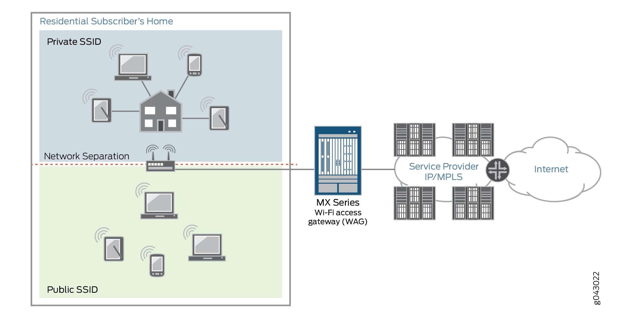
After deploying a WAG, service providers can configure the WAG to provide secure wireless connectivity for devices such as computers, laptops, tablets, gaming systems, and mobile phones.
WAG offers wireline and mobile service providers the following deployments and business value opportunities:
-
Wireline service providers–The WAG deployment is based on an in-home division of access points or public access points, and works with any Wi-Fi access point that creates a generic routing encapsulation (GRE) tunnel to the MX Series router. This deployment protects subscribers and reduces churn by offering free Wi-Fi with a paid wireline subscription. For added value, service providers can also sell ad hoc access or mode, such as airport, public safety, search-and-rescue, and café access.
-
Mobile service providers–The WAG deployment is based on the mobile service provider’s own access points, or wholesale and retail with the wireline service provider. Service providers that offer quadruple play, where TV, Internet, wireless, and landline phone services are combined, can leverage both wireline and wireless assets. This deployment helps reduce costs in mobile packet core and radio access network infrastructures by offloading mobile data through Wi-Fi access points. This approach reduces congestion on licensed spectrum while maintaining user identity and associated services, and expands overall service coverage. With a trusted Wi-Fi, mobile providers can integrate hotspots into their policy and accounting infrastructure, allowing operators to maintain customer visibility on their networks and provide a seamless Wi-Fi access experience to the end user.
Subscriber services use dynamic-bridged generic routing encapsulation (soft GRE) tunnels to support WAG deployments by enabling Layer 2 traffic exchange between the customer premises equipment (CPE) and the BNG. See Wi-Fi Access Gateway Deployment Model Overview. The CPE can either be a Dynamic Host Configuration Protocol (DHCP) or Point-to-Point Protocol over Ethernet (PPPoE) client. Because soft GRE is stateless, the BNG removes the tunnel when the subscriber logs out and does not maintain tunnel state when no active subscriber session exists, improving scalability. The following key features are supported:
-
Dynamic creation and deletion of GRE tunnels
-
GRE tunnels on VLAN tagged and untagged interfaces
-
IPv4 and IPv6 GRE tunnels
-
VLAN tagged and untagged GRE playloads
-
IPv4 and IPv6 DHCP or PPPoE subscriber termination over GRE
The WAG supports per-subscriber services for subscribers connected through GRE tunnels, including:
-
Authentication, authorization, and accounting (AAA)
-
IP address assignment
-
Hierarchical quality of service (QoS)
-
Lawful intercept
-
Class of service (CoS)
Benefits of Wi-Fi Access Gateway
-
Authenticates Wi‑Fi users even when they are not directly connected to the WAG at Layer 2, because GRE tunnels carry Layer 2 information across an IP network.
-
Applies services based on user equipment (UE)–specific identifiers, such as the MAC address or Subscriber Identity Module (SIM) card.
-
Applies services in the network, rather than limiting them to the Wi-Fi access point.
-
Supports soft GRE or Ethernet over GRE on most Wi‑Fi access points. For Ethernet over GRE services, you need to configure only one end of the tunnel; the other end dynamically learns remote IP addresses by inspecting incoming GRE packets.
-
Improves network scalability by enabling seamless integration and supporting Layer 3 termination for user equipment (UE).
-
Supports both VLAN-tagged and untagged Ethernet frames, providing flexibility for diverse deployment conditions.
-
Supports high availability and redundancy in Wi-Fi offload conditions, allowing for reliable network performance under various operational conditions.
-
Supports retrieval of soft GRE information through Junos telemetry. To configure Junos telemetry, see Junos Telemetry Interface User Guide | Junos OS | Juniper Networks. For a complete list of soft GRE sensors and sensor path information, see Junos YANG Data Model Explorer.
See Also
Wi-Fi Access Gateway Deployment Model Overview
Figure 2 shows an MX Series router broadband network gateway (BNG) deployed as a Wi-Fi access gateway (WAG). The WAG provides a multiservice edge with a full broadband feature set that is highly reliable because of the included redundant hardware. Ethernet frames from the user equipment device must be tunneled to the BNG across an IP cloud or public Internet.
Broadband edge subscriber service over softGRE tunnel is developed to support Wi-fi Offload Gateway deployments. This integration facilitates Layer 2 transmission to user equipment (UE) through Ethernet frames encapsulated in GRE headers. The configuration supports DHCP and PPPoE dual stack access models, allowing VLAN-tagged or untagged Ethernet frames.
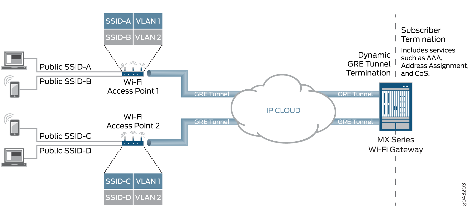
To support the MX Series BNG deployed as a WAG, dynamic-bridged generic routing encapsulation (GRE) tunnels are created and terminated at the BNG when it receives GRE traffic from the wireless access point (WAP). Dynamic Host Configuration Protocol (DHCP) or PPPoE subscribers are transported through GRE tunnels as either VLAN-tagged per service set identifier (SSID) or untagged. When the user equipment device connects to the SSID and begins to send traffic, the access point initiates a Layer 2 soft GRE or Ethernet-over-GRE connection to the MX Series BNG and the BNG dynamically builds the GRE tunnel. The softGRE tunnel configuration of source IP address, destination IP network, and associated PS interface is used to enable dynamic GRE tunnel creation service. The PS interface is anchored over logical tunnel interfaces. GRE tunnels are cleared after all of the subscribers within a GRE tunnel have logged out and a configurable timer has expired. Fault tolerance and service availability is supported through the use of Layer 2 softGRE tunnel anchored on redundant GRE tunnels, ensuring continuous connectivity even in the event of a failure.
This deployment model supports a full set of services per user equipment device and per access point. Subscriber services such as authentication, authorization, and accounting (AAA); address assignment; hierarchical quality of service (QoS); lawful intercept; and class of service (CoS) are supported for individual DHCP subscribers and PPPoE subscribers within the GRE tunnels. No additional service cards are required for GRE or QoS because all features run inline on MPCs.
External RADIUS proxy supports Extensible Authentication Protocol (EAP) Subscriber Identity Module (SIM), Tunneled Transport Layer Security (TTLS), and Authentication and Key Agreement (AKA) protocols. The External RADIUS proxy also integrates with HTTP redirect to the Web portal.
The MX Series as WAG deployment model also supports the wholesale of access point access to multiple retail service providers. This wholesaling allows the local breakout of traffic or Layer 3 handoff to retail service providers.
Supported Access Models for Dynamic-Bridged GRE Tunnels on the Wi-Fi Access Gateway
DHCP and PPPoE subscriber access modules are supported for packets carried over dynamic-bridged generic routing encapsulation (GRE) tunnels. Dynamic-bridged generic routing encapsulation (GRE) tunnels and the Wi-Fi access gateway support interface stacks for VLAN-tagged and untagged subscribers. Subscriber features such as authentication, address assignment, Class of service (CoS), dynamic and service profiles for DHCP subscribers, lawful intercept, firewall filters, and change of authorization (CoA) are supported.
Scaling limitations of pseudowire subscriber interface devices (psn IFDs) require multiple tunnels to share the same psn IFD. The pseudowire is a virtual device that is stacked above the logical tunnel anchor point on the physical interface (the IFD).
The system does not allow a psn IFD used for dynamic GRE tunnel termination to service MPLS pseudowire termination. Subscriber services and lawful intercept are supported only at the IP demultiplexing (demux) interface level.
A GRE tunnel cannot have both untagged and tagged subscribers.
The tagged model and the untagged model are described in the following sections:
Dynamic VLAN-Tagged Subscribers
To simplify provisioning and troubleshooting for VLAN-tagged subscribers, configure all Wi-Fi access points to use the same set of VLANs. This configuration allows a single pseudowire subscriber logical interface (psn IFL), associated with a VLAN ID on a psn IFD, to represent multiple GRE tunnels.
A dynamic VLAN demux interface (demux0.yyyyyyyy) is created for each VLAN tag and is stacked over the tunnel psn interface (psn.xxxxxxxx). Multiple VLANs (single and dual-tagged) can exist over the same GRE tunnel. The subscribers' IP demux interfaces are then created over the VLAN demux interface.
Untagged Subscribers
The system creates untagged DHCP or PPPoE subscribers directly over the GRE tunnel. For each subscriber, it creates an IP demux interface (demux0.yyyyyyyy) stacked over the tunnel psn logical interface (psn.xxxxxxxx). The system can support multiple subscribers over the same GRE tunnel.
Wi-Fi Access Gateway Configuration Overview
To configure the MX Series router as a Wi-Fi access gateway (WAG):
Configuring a Pseudowire Subscriber Logical Interface Device for the Wi-Fi Access Gateway
Before you begin, you must create a logical tunnel interface:
Configure the maximum number of pseudowire logical interfaces devices. See Configuring the Maximum Number of Pseudowire Logical Interface Devices Supported on the Router.
Configure a tunnel interface. See Tunnel Interface Configuration on MX Series Routers Overview.
To configure the pseudowire subscriber logical interface device on which the dynamic-bridged GRE tunnel is built on the MX Series router Wi-Fi access gateway:
Configuring Conditions for Enabling Dynamic-Bridged GRE Tunnel Creation
Before you begin:
Configure the pseudowire logical device on which you need to build the dynamic-bridged GRE tunnel. See Configuring a Pseudowire Subscriber Logical Interface Device for the Wi-Fi Access Gateway.
Configure interface lo0 with the source IP address of the GRE tunnels for the Wi-Fi access gateway (WAG). Use the IP address of the MX Series router that you want to receive the incoming GRE traffic. This address cannot be the primary or preferred address on lo0. See Configuring a Loopback Interface.
To configure the conditions for enabling dynamic-bridged generic routing encapsulation (GRE)
tunnel creation, you configure one or more GRE tunnel groups. Multiple GRE tunnel groups can
have the same source-address or the same
destination-networks value, but you cannot use a specific
source-address
and
destination-networks combination in more than one GRE tunnel group.
To configure a GRE tunnel group:
Configuring VLAN Subscriber Interfaces for Dynamic-Bridged GRE Tunnels on Wi-Fi Access Gateways
To configure subscriber interfaces for VLAN-tagged Dynamic Host Configuration Protocol (DHCP) or Point-to-Point Protocol over Ethernet (PPPoE) subscribers on dynamic-bridged generic routing encapsulation (GRE) tunnels:
Configuring Untagged Subscriber for Dynamic-Bridged GRE Tunnels on Wi-Fi Access Gateways
To configure subscriber interfaces for untagged Dynamic Host Configuration Protocol (DHCP) or Point-to-Point Protocol over Ethernet (PPPoE) subscribers on dynamic-bridged generic routing encapsulation (GRE) tunnels:
Change History Table
Feature support is determined by the platform and release you are using. Use Feature Explorer to determine if a feature is supported on your platform.