What Is Segment Routing and Source Packet Routing in Networking?
In a segment-routed network, devices generate a series of instructions that represent the ways that a packet can be forwarded or processed. These instructions are called segments. By stacking segments together, operators can create precise paths between any two devices. This enables features such as a BGP-free core, traffic engineering (TE), backup paths, multi-domain paths, and multi-topology networking. In the data plane, segments can be represented using MPLS labels or IPv6 addresses.
Prerequisite Knowledge
We assume that the readers understand general IP routing and MPLS label switching principles and have a strong working knowledge of either IS-IS or OSPF. We've covered these concepts in other resources in our Technical Documentation.
Segment routing (SR) is a method of generating a series of instructions that indicate how a packet can be forwarded or processed across a topology. These instructions are called segments. These instructions can then be written onto a packet so that transit devices forward and process the packet as intended. Multiple segments can be stacked together to define an end-to-end path between any two devices.
Segments are advertised directly inside routing protocols such as IS-IS, OSPF, and BGP. This means there is no need to run an additional protocol to advertise these segments throughout the network. This section defines the concept of a segment. This section also covers how segments are advertised, and how they can be used to create a precise path across a network. We further explore how these segments can be represented in the data plane by using MPLS labels or by using special IPv6 addresses called SRv6 addresses. These options are called SR-MPLS and SRv6, respectively.
Examples of Instructions Represented by Segments
A segment is the name given to a construct that represents one single instruction. This could be an instruction related to forwarding, or it could be an instruction relating to how the packet should be processed locally at the receiving router.In segment routing, these instructions are advertised throughout the network—for example, throughout an IS-IS level or an OSPF area. The result is that any SR-capable device can stack these instructions together to create a precise path across the network to any arbitrary remote device.
Here are a few examples of instructions that a segment can represent:
-
Forward a packet down the interior gateway protocol (IGP) shortest path to a particular remote router.
-
Instruct a transit router to send the packet directly to a next-hop neighbor, and therefore out of a specific local interface.
-
Instruct an autonomous system (AS) border router to send the packet toward a specific external BGP (EBGP) peer, overriding the BGP best-path decision.
-
Load-balance a packet between two or more transit or endpoint routers.
-
Send a packet towards the nearest border router out of multiple potential exit points.
-
Instruct a transit router to redirect the packet down a specific traffic-engineered (TE) tunnel.
-
Define a smaller constrained topology within your main topology, and then forward a packet down the shortest path within that constrained topology.
-
Remove all the segment instructions that have been pushed onto the packet, and then process the packet itself in a specific Layer 2 or Layer 3 forwarding table.
Segments Are Advertised Inside Your Existing Routing Protocols
In an SR network, each device generates a variety of segments that represent how it can forward or process a packet. The majority of these segments are then advertised to all other routers inside the same routing domain, such as the same OSPF area or IS-IS level, or between BGP peers.
Instead of using a dedicated protocol, segment routing advertises segments directly in IS-IS, OSPF, and BGP through protocol extensions. You don't need to enable new protocols for segment routing. You can simply rely on the protocols that you already use.
As a result, every SR-enabled device in your routing domain has full visibility of every segment instruction that has been advertised by every other SR-enabled node in the network. In other words, every device learns about every advertised segment that every other device can receive.
Figure 1 demonstrates this idea and shows a high-level example of what segments look like in an SR-MPLS network. The concept is similar in SRv6.
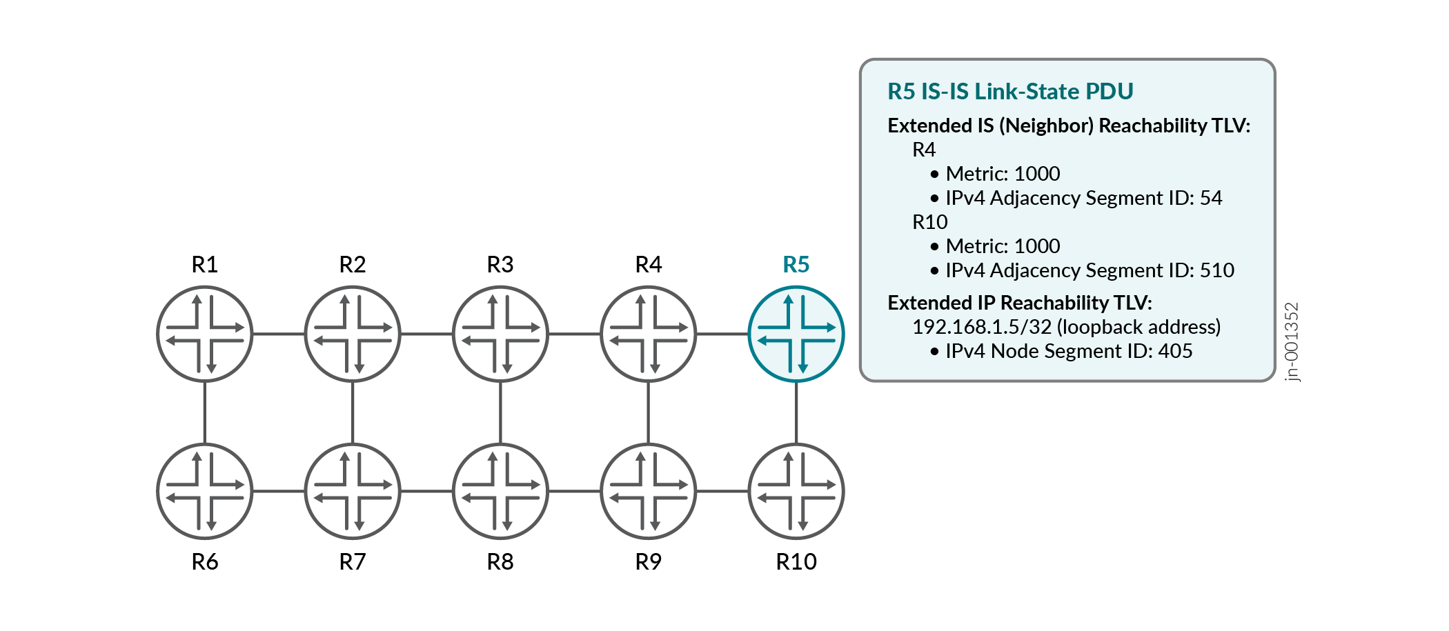
Figure 1 shows a topology of 10 routers, numbered R1 to R10. In a link-state network, every router generates an object that describes its place in the network. OSPF calls this object a link-state advertisement (LSA), while IS-IS calls it a link-state protocol data unit (LSP). In both cases, SR can append additional information to this LSA or LSP.
For example, in Figure 1, R5 has announced that it has adjacencies to R4 and R10. Segment routing can tag this information in the LSA or LSP with a segment instruction that says R5 can use segment routing to send traffic directly to these neighbors, along with a number called the segment identifier (SID). These are called adjacency segments in SR-MPLS. The equivalent construct in SRv6 is called an End.X SID.
R5 has also tagged its own loopback IPv4 address prefix with an instruction that indicates R5 is willing to accept traffic that has been sent down the IGP shortest path. This is called a node segment in SR-MPLS.
The LSA or LSP is flooded throughout the routing domain, which means that every router in the OSPF area or IS-IS level learns about every single segment that has been advertised using these protocols. Using this segment information, SR capable routers can stack one or more segment instructions directly onto a packet to indicate the path that the packet should take to a particular remote router, along with information about the way that the packet should be processed.
Combine Segments to Create a Precise Path Across a Network
After every router has announced the various segments that represent the instructions it has generated, any router in the network can combine these segments together to create any arbitrary path of your choice. This may involve creating a stack of segments, or it may be as simple as using one single shortest-path segment to the destination router.
Segment routing achieves this without the need to actively signal or request the path, because all of the segment instructions have already been advertised and learned by existing routing protocols. Any router can simply calculate the required path, extract the required segments associated with that path, and then append those instructions onto the packet in the data plane.
Figure 2 shows a human-readable example of how these segments can be combined together.
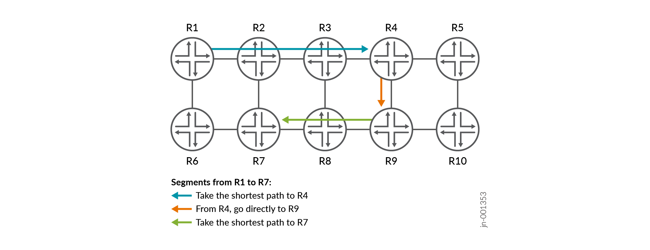
Starting from R1, the figure shows a series of three instructions that send a packet towards R7. The first segment follows the shortest path to R4. The second segment goes directly from R4 to R9. The final instruction takes the shortest path to R7.
R4 generated and advertised the first two segments. R7 generated the third segment. Any router in the network can then take advantage of these segments to create a precise path across a topology.
You don't need to use a stack of segments. For example, if your only requirement is for traffic to follow the shortest path to a remote device, then the packet will require only one segment. This is shown in Figure 3, where only one segment is required to describe the shortest path between R1 and R5.
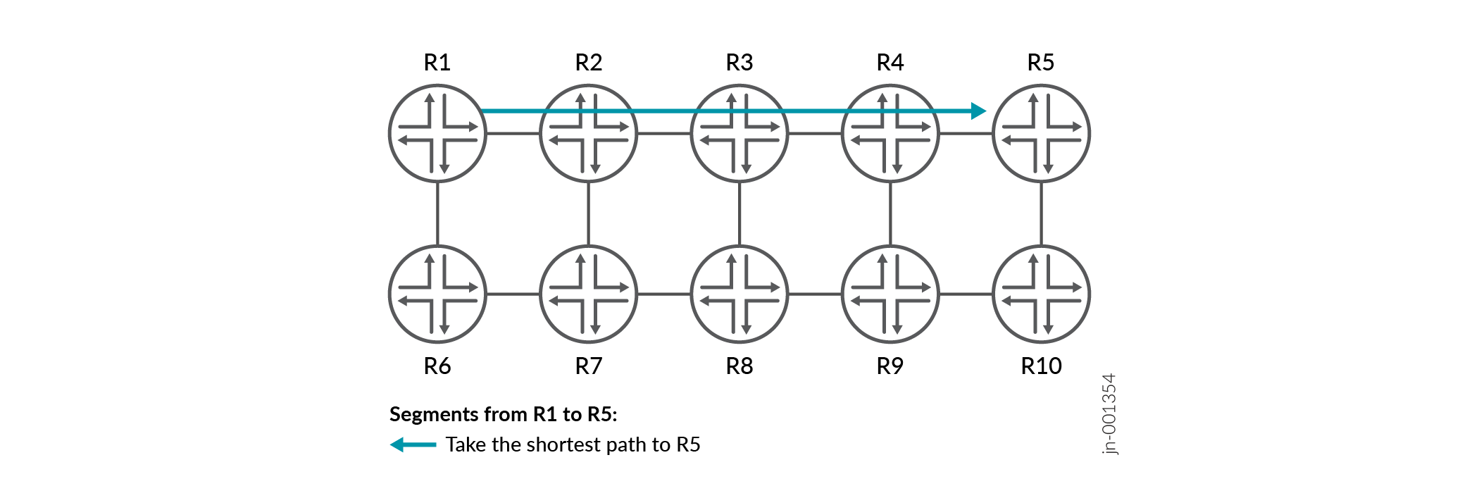
This is enough to enable a classic BGP-free core design without traffic engineering, where packets simply follow the IGP shortest path to the destination border router.
Using MPLS or IPv6 to Represent Segments in the Data Plane
In the data plane, segments can be represented using MPLS labels or IPv6 addresses. These methods are called SR-MPLS and SRv6, respectively.
Figure 4 shows a high-level overview of what each protocol looks like in the data plane. SR-MPLS uses one MPLS label to represent a single segment, while SRv6 can encode one or more segments inside a single IPv6 address. When multiple IPv6 addresses are required to describe the full path, these addresses are stored inside an IPv6 extension header called the Segment Routing Header (SRH).
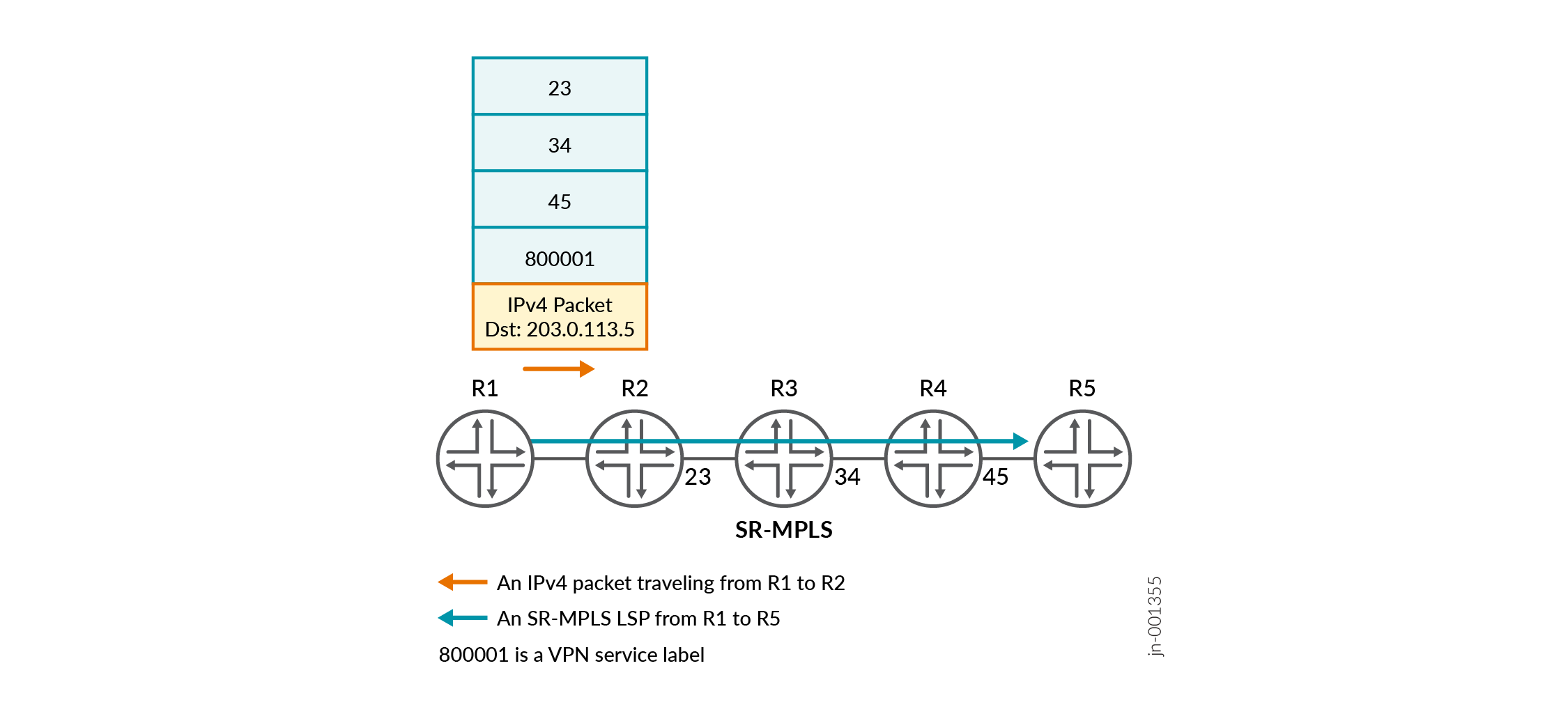
Figure 4 demonstrates a stack of segments in each data plane protocol. However, if a packet simply needs to follow the shortest path to a remote device, then it is not necessary to use a stack of segments. Instead, this instruction can be encoded inside a single MPLS label or IPv6 address.
SR-MPLS and SRv6 both use a numerical construct called a segment identifier (SID). SID is used to communicate the MPLS label or IPv6 address that should be used in the data plane. The SID value is used in different ways depending on the type of segment being advertised.
For example, in SR-MPLS, the SID value is sometimes the exact MPLS label that a router expects to receive for that segment. However, other segment types use the SID value as an index that can be combined with a pre-allocated set of MPLS labels to calculate the correct MPLS label that a router expects to receive for a segment.
In contrast, SRv6 deployments tend to allocate an entire unique subnet of IPv6 addresses to each individual router in the network. Routers then allocate individual segments from this larger prefix. The segments and the prefix are both advertised around the network in such a way that any router can, at the very least, follow the metrically shortest path toward that segment.
Both IS-IS and OSPF create and advertise the same type of segments, and they both use the segment ID value in the same way. However, each protocol has its own unique way of advertising this information.
Refer to our documentation that explores SR-MPLS and SRv6 separately and in greater detail, along with the IS-IS and OSPF configuration that enables these data plane protocols and the unique segment types offered by SR-MPLS and SRv6. Before reading this detailed documentation, readers are strongly advised to first read the documents mentioned in the section below to gain a broad understanding of segment routing in general.
What's Next
We strongly recommend reading the following articles for a general understanding of segment routing: