What Features and Designs Does Segment Routing Enable?
Segment routing enables many useful features, including a BGP-free core, traffic engineering (TE), local repair backup paths, anycast routing, and multi-topology networking. All of these features require no additional signaling, and are powered by existing routing protocols. Additionally, centralized controllers can create bandwidth reservations and traffic-engineered paths across IGP areas and levels, and BGP autonomous systems.
Prerequisite Knowledge
We assume that you've read What Is Segment Routing and Source Packet Routing in Networking?, along with the prerequisite topics.
Segment routing (SR) offers many powerful features that add tremendous value to a variety of networks, including service provider networks, data center networks, mobile networks, and large enterprise networks.
Some of these features are exclusive to segment routing. Existing path protocols and tunneling protocols such as RSVP and LDP also offer some other features. Even in this case, segment routing offers new advantages and enhancements when compared to existing options.
This document provides a high-level overview of these features and a broad understanding of the benefits of deploying segment routing. We also offer various documents that explain each of these features in greater technical detail, including their configuration and verification.
All the features described in this guide are available for SR-MPLS. Most features are also available for SRv6.
Automatic Full-Mesh of Shortest-Path Tunnels to Other SR-Enabled Devices
When an operator runs MPLS and LDP on Junos OS routers, the result is that each device automatically creates a full mesh of label-switched paths (LSPs) to every other LDP device in the network. These LSPs simply follow the IGP shortest path to the destination. This is enough to power a BGP-free core, or VPN services such as Ethernet VPN (EVPN) and Layer 3 VPNs (L3VPN).
Segment routing automatically creates shortest-path tunnels to all other SR-enabled devices, for both SR-MPLS and SRv6.
In an SR-MPLS network, the inet.3 routing tables can be automatically populated with IPv4 LSPs to all other SR-MPLS enabled devices. This is true even in the most basic of SR-MPLS deployments. If you also run IPv6 in your network, it is also easy to populate the inet6.3 table with IPv6 LSPs.
Figure 1 demonstrates this concept. It shows a network of ten routers, numbered R1 to R10.
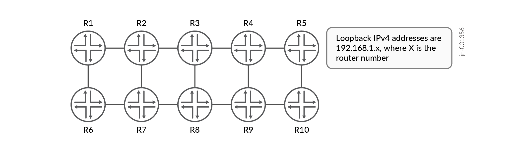
After enabling SR-MPLS with IS-IS, the output below shows that router R1's inet.3 table contains a full mesh of LSPs to the other nine routers. SR-MPLS automatically creates this full mesh, requiring no additional signaling.
user@R1> show route table inet.3

inet.3: 9 destinations, 9 routes (9 active, 0 holddown, 0 hidden)
+ = Active Route, - = Last Active, * = Both

192.168.1.2/32     *[L-ISIS/14] 00:06:45, metric 100
                    >  to 10.1.2.2 via ge-0/0/0.0
192.168.1.3/32     *[L-ISIS/14] 00:02:18, metric 200
                    >  to 10.1.2.2 via ge-0/0/0.0, Push 300403
192.168.1.4/32     *[L-ISIS/14] 00:02:18, metric 300
                    >  to 10.1.2.2 via ge-0/0/0.0, Push 300404
192.168.1.5/32     *[L-ISIS/14] 00:02:18, metric 400
                    >  to 10.1.2.2 via ge-0/0/0.0, Push 300405
192.168.1.6/32     *[L-ISIS/14] 00:06:45, metric 100
                    >  to 10.1.6.6 via ge-0/0/2.0
192.168.1.7/32     *[L-ISIS/14] 00:02:18, metric 200
                       to 10.1.2.2 via ge-0/0/0.0, Push 300407
                    >  to 10.1.6.6 via ge-0/0/2.0, Push 300407
192.168.1.8/32     *[L-ISIS/14] 00:02:18, metric 300
                    >  to 10.1.2.2 via ge-0/0/0.0, Push 300408
                       to 10.1.6.6 via ge-0/0/2.0, Push 300408
192.168.1.9/32     *[L-ISIS/14] 00:02:18, metric 400
                    >  to 10.1.2.2 via ge-0/0/0.0, Push 300409
                       to 10.1.6.6 via ge-0/0/2.0, Push 300409
192.168.1.10/32    *[L-ISIS/14] 00:02:18, metric 500
                    >  to 10.1.2.2 via ge-0/0/0.0, Push 300410
                       to 10.1.6.6 via ge-0/0/2.0, Push 300410
Note that the outgoing MPLS label appears to be predictable for each remote node. This is not the default behavior of SR-MPLS, but it is very easy to enable with just a few lines of configuration. Note that the LSPs to R7, R8, R9, and R10 automatically take advantage of equal-cost multipath (ECMP) options.
In an SRv6 network, if all the devices run SRv6, then you can create an automatic full mesh of tunnels to all other SRv6-enabled devices. However, there is no strict requirement to run SRv6 on all of your transit devices. For example, if an older transit device cannot run SRv6, then these devices can still be enabled for regular IPv6. This will be enough for these routers to offer transit functionality to the SRv6 tunnels in your network. In this case, you'll have at least a partial mesh of tunnels to every other SRv6-enabled device.
Flexible Algorithm
Flexible Algorithm or Flex Algo is a scalable method of creating multitopology networks. Using admin groups, you can tag certain links as belonging to a particular Flex Algo topology. New segment instructions are then created that are unique to that topology. This guarantees that traffic will only ever be contained within your topology. The traffic will never leak out to routers that are not part of the topology because the devices inside the topology routes the traffic within the topology.
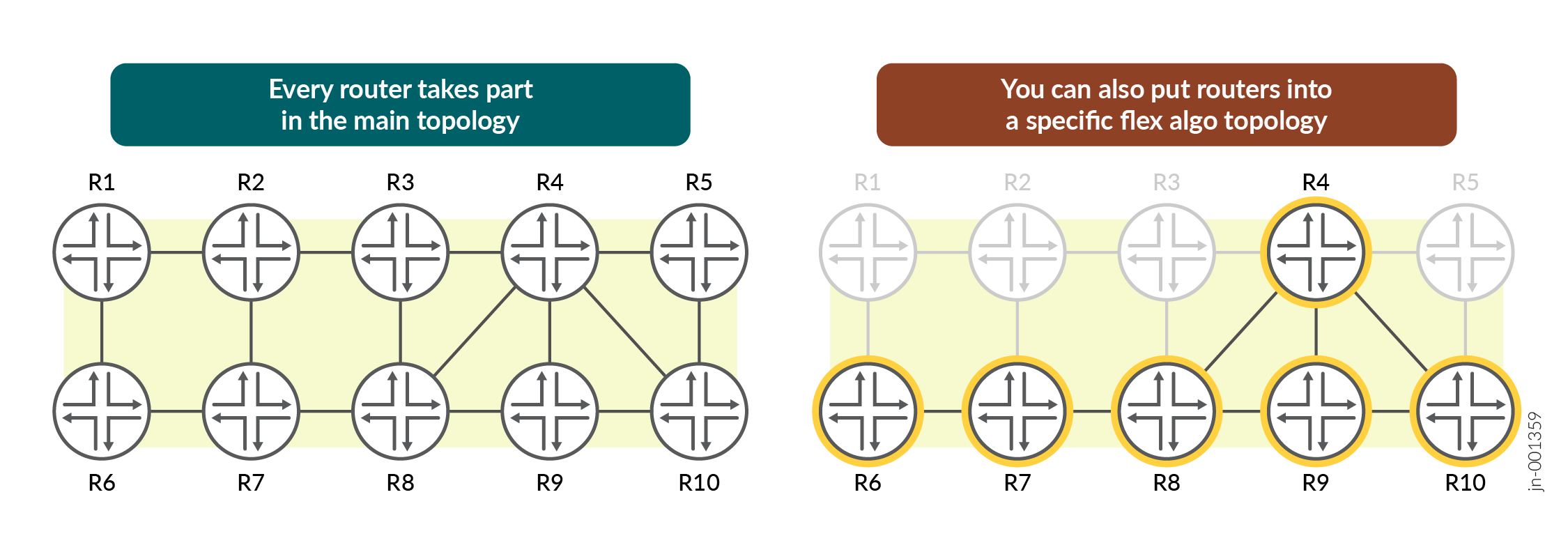
Figure 2 demonstrates this concept. Every single router takes part in the main topology. Then, certain links can additionally take part in one or more smaller topologies.
Traditional multi-topology methods required great effort to configure and maintain. In contrast, using admin groups gives you the option to reuse admin groups between topologies, or to choose whether to exclude or include one or more admin groups.
Each topology is associated with a numerical color. This enables Flex Algo to take advantage of the BGP color community to automatically bind a prefix to a particular topology. This offers a much more scalable solution than historical methods of binding a prefix to a specific multi-topology network.
Topology-Independent Loop-Free Alternate (TI-LFA)
TI-LFA creates local repair backup paths that can be used immediately in times of link or node failure. There are other protocols that also offer local repair paths. However, some of these protocols can only offer limited topology coverage due to the requirement to avoid backup paths that might create a loop. Other protocols can cover the entire network, but each backup path needs to be set up and maintained separately.
In contrast, TI-LFA offers 100% topology coverage with no additional signaling. By pushing a series of segments onto a packet, topological loops are completely avoided. In addition, TI-LFA backup paths are identical to the path that will be used once the network has finished converging from the link or node failure. This is called the post-convergence path. This means traffic doesn't need to shift a second time to a new post-convergence path once it's moved to a backup path. This reduces network jitter.
When we pre-install these backup paths into the forwarding plane, we often observe that we can reduce downtime to as little as 50ms during the switchover.
You can also use the TI-LFA backup paths to protect plain IP traffic. Further, Flex Algo topologies automatically ensure that TI-LFA backup paths are contained only within the topology that you have designed. TI-LFA is a powerful feature, and is one of the primary drivers that network operators consider when choosing whether to deploy segment routing.
Microloop Avoidance
In link-state networks, different routers learn and process topology change updates at different times. This can create temporary loops during network convergence events. For example, if one router converges before a neighboring router, and decides that its neighbor is the next best hop, then the neighboring router might send the packet back again if the neighbor has not yet finished converging. These loops are known as microloops.
Microloops are brief, millisecond events. However, in the modern era, a substantial quantity of traffic can transit across a link in that time. Microloops have the power to temporarily flood a link with traffic, which could potentially cause a complete outage on that link during this time.
Microloop avoidance (MLA) is feature in segment routing that identifies areas in your topology where microloops might occur. Then, when a link or node fails, Junos OS can temporarily push segment instructions to ensure that remote routers will forward the traffic correctly, even if they have not yet finished converging to the new topology. These segments are often used for no more than a few seconds, but this can be enough to prevent a catastrophic outage during the convergence process.
Anycast
If you configure a prefix on two or more routers, then both devices can announce a segment that represents the instruction to send traffic down the shortest path toward that prefix. This may be a prefix on a shared point-to-point or broadcast link, or it could be a /32 IPv4 or /128 IPv6 address that is configured on two or more devices.
As a result, you can send traffic down the shortest path toward the metrically closest router. Or, if all devices have equal cost, you can load-balance traffic between them..
This feature is known as anycast routing. It is common in the core of a network. By configuring two or more core routers to announce the same segment, you can create a TE path that also has the ability to take advantage of equal-cost paths when they are available. This is not possible in protocols such as RSVP, where you need to create two or more separate explicit paths if you want to load-balance across those paths.
A less common but powerful example is to configure two or more router borders to announce the same prefix and segment. If you use this shared segment as a BGP protocol next-hop, you can then create a design where traffic is simply transported to the closest egress point.
On-Demand Next-Hops
Traffic engineering historically required network operators to configure individual TE paths on each ingress PE router toward every egress router. Many of these TE paths shared similar TE characteristics. For example, every single TE path might be configured to use TE metrics instead of IGP metrics, or to avoid an admin group that indicates whether a link will soon undergo maintenance.
As an alternative to individually defining all the endpoints to your paths on each PE router, segment routing offers the ability to automatically detect when a TE path should be created. This feature is called On-Demand Next-Hops (ODN).
When you run ODN in an SR network, paths are automatically calculated and built to any valid BGP protocol next-hop on any valid BGP prefix. The path to the remote PE is then calculated using D-CSPF, based on constraints of your choice. This offers a solution that is much more scalable than manually defining all of your endpoints individually.
This feature is also available in RSVP. Once again though, in a segment routed network, you don't need to signal or maintain these paths.
Controller-Based Traffic Engineering
Using an external controller (such as Juniper Paragon Pathfinder), you can run a protocol called Path Computation Element Protocol (PCEP) that can communicate directly with every SR enabled device in your network. The controller can calculate TE paths on behalf of all the devices in the network, and then use PCEP to write those paths directly to the ingress router of that path.
One or more SR-enabled routers can advertise topology information to the controller using BGP Link-State (BGP-LS). This enables the controller to learn your topology without also becoming a part of the same link-state topology. The controller can then automatically generate a graphical view of your topology and the tunnels that travel across that topology.
If you have multiple routing domains (such as different OSPF areas, IS-IS levels, or autonomous systems), then you can configure devices in each of these domains to advertise the topology to your controller. As a result, the controller can calculate paths across domain boundaries, and then inform an ingress router of the exact segments that should be written onto the packet, regardless of how many routing domains the tunnel travels across.
The controller can also offer additional services that are not offered by segment routing itself, such as bandwidth reservations on a per-path basis. The controller can also fully optimize paths in response to network events, such as moving a less important tunnel on one device to another path to make room for a higher priority tunnel on another device.
Color-Aware Traffic Engineering
Network operators often create multiple tunnels between two endpoints so that each tunnel can follow a different path based on the importance of the traffic. For example, delay-sensitive traffic might take a shorter path than best-effort traffic. Similarly, best-effort traffic might be deliberately routed away from the physically shortest links in your network, so that delay-sensitive traffic can take the quickest path without competing with the best-effort traffic.
Historically, this feature requires the use of complex routing policies to map individual BGP prefixes to particular paths. These routing policies often need to be manually maintained, and can easily be misconfigured.
In contrast, segment routing offers you the ability to tag your tunnels with a color, which is simply a numerical identifier that represents the intent of the tunnel. For example, you might choose to assign color value 10 to any tunnel on any router that carries best-effort traffic. As another example, you might use color value 20 to represent tunnels that carry delay-sensitive traffic.
You can then take advantage of the BGP color community to automatically bind a learned prefix to a TE tunnel with a matching color. This removes the traditional complexity of manually creating routing policies to achieve the same goal. It also offers you a much more scalable method of deploying multiple paths to a destination.
Figure 3 demonstrates this concept.
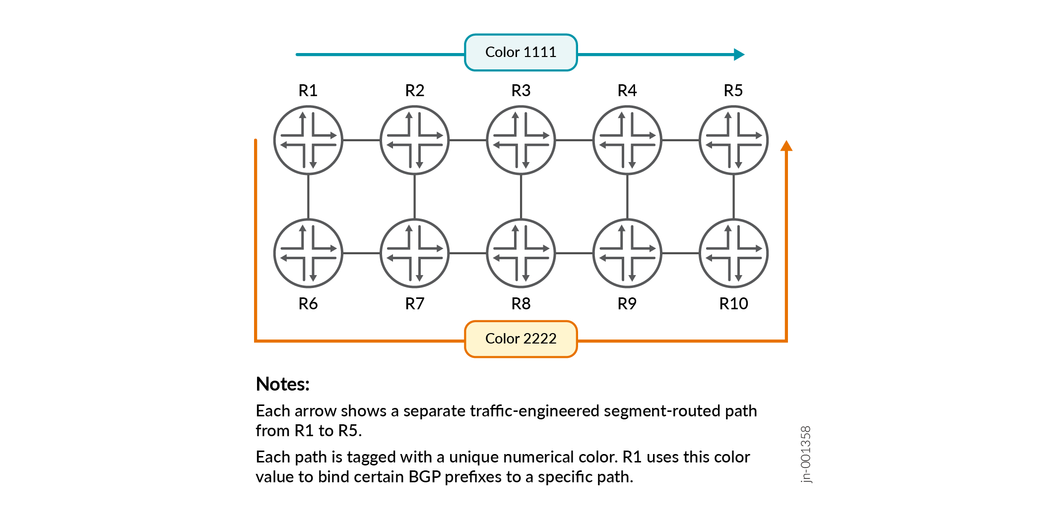
R1 has two paths to the remote router R5. One path is used by delay-sensitive traffic, and the other is used for traffic destined to the public Internet. When R5 advertises BGP prefixes that are delay sensitive, R5 can attach BGP color community value 1111 to these prefixes. R1 will then automatically associate these prefixes with the path that has a matching color value.