Layer 2 Protocol Tunneling (L2PT)
Use Layer 2 protocol tunneling (L2PT) to tunnel supported Layer 2 protocols across a network to devices that are not part of the local broadcast domain.
Understanding Layer 2 Protocol Tunneling
Juniper Networks Ethernet switches and routers use Layer 2 protocol tunneling (L2PT) to send Layer 2 protocol data units (PDUs) across the network and deliver them to devices that are not part of the local broadcast domain. This feature is useful when you want to run Layer 2 protocols on a network that includes switches located at remote sites that are connected across a service provider network.
You can also use L2PT to tunnel protocols between two locally-connected user-to-network interfaces (UNIs) in the same broadcast domain, but in that case, the device floods protocol packets in the VLAN instead of rewriting the packets with the tunnel MAC address.
Use Feature Explorer to confirm platform and release support for specific features.
Review the Platform-Specific L2PT Behavior section for notes related to your platform.
- Benefits of L2PT
- How L2PT Works
- VLAN Configuration Requirements for Configuring L2PT on Switches
- Layer 2 Control Protocol Tunneling in Layer 2 VPN
- Layer 2 Control Protocol (L2CP) Transparent Tunneling
Benefits of L2PT
-
Enables you to run supported Layer 2 protocols in a tunnel across a service provider network to remote sites.
-
Provides a single spanning-tree protocol domain for subscribers across a service provider network.
How L2PT Works
L2PT works by encapsulating Layer 2 PDUs, tunneling them across a service provider network, and decapsulating them for delivery to their destination switches. The ingress service provider edge (PE) device encapsulates Layer 2 PDUs by rewriting the PDUs’ destination media access control (MAC) addresses before forwarding them onto the service provider network. The devices in the service provider network treat these encapsulated PDUs as multicast Ethernet packets. Upon receipt of these PDUs, the egress PE devices decapsulate them by replacing the destination MAC addresses with the address of the Layer 2 protocol that is being tunneled before forwarding the PDUs to their destination devices.
When a PE port configured for Layer 2 protocol tunneling receives a control packet for a supported Layer 2 protocol, the PE device rewrites the multicast destination MAC address with the predefined multicast tunnel MAC address 01:00:0C:CD:CD:D0. The PE device then sends the modified packet onto the provider network. The packet travels across the provider network transparently across the service provider network with the tunnel MAC address. All devices on the provider network treat these packets as multicast Ethernet packets and deliver them to all PE devices for the customer. The egress PE devices receive all the control PDUs with the tunnel MAC address, identify the packet type by doing deeper packet inspection, and replace the destination MAC address with the appropriate destination MAC address. The egress PE devices send out the modified PDUs to the customer PE devices, and the original MAC address is restored when the packets reach the destination ports.
The L2PT protocol is valid for all types of packets, such as untagged, tagged, and Q-in-Q tagged packets.
If a PE device receives a packet on a tunnel interface that already has a destination MAC
address of 01:00:0C:CD:CD:D0, the device puts the port into an error state and shuts down the
port. You can clear this error condition on an interface using the CLI by entering the
clear error mac-rewrite interface interface-name
command on
the following devices that support L2PT:
-
MX Series and ACX Series routers
-
EX Series switches that use Enhanced Layer 2 Software (ELS)
-
QFX Series switches
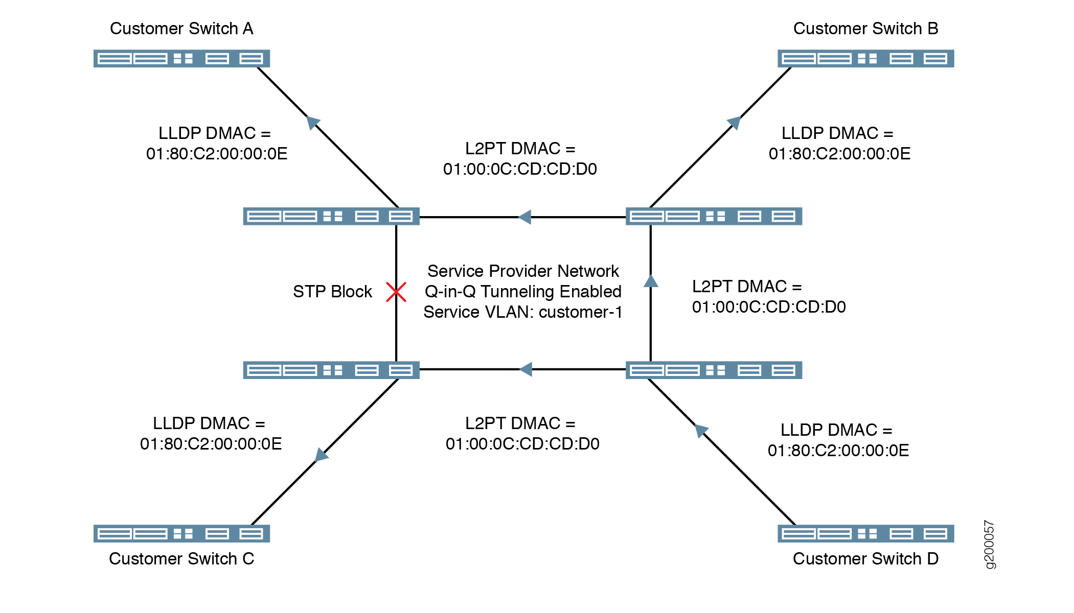
Figure 1 illustrates an example of the L2PT process with EX Series switches in a service provider network that are configured to tunnel LLDP packets on a service VLAN with Q-in-Q tunneling enabled.
-
Customer Switch D sends an LLDP PDU to the service provider network that is ultimately intended for the other switches in the customer network.
-
The receiving provider switch rewrites the LLDP destination MAC address with the L2PT destination MAC address, and sends the frame with the encapsulated LLDP PDU to the other switches in the service provider network.
-
When the other service provider switches receive the frame, they detect the L2PT destination MAC address, restore the LLDP destination MAC address, and forward it to Customer Switches A, B, and C.
VLAN Configuration Requirements for Configuring L2PT on Switches
On switches, you enable L2PT on a per-VLAN basis. When you enable L2PT for a particular
Layer 2 protocol on a VLAN, all access interfaces are considered to be customer-facing
interfaces and all trunk interfaces are considered to be service provider network-facing
interfaces. You cannot configure the specified protocol on the access interfaces. L2PT only acts
on logical interfaces with family ethernet-switching. The switch floods L2PT
PDUs to all trunk and access ports within a given S-VLAN.
Access interfaces in an L2PT-enabled VLAN should not receive L2PT-tunneled PDUs. If an access interface does receive L2PT-tunneled PDUs, there might be a loop in the network, and the device will shut down the interface.
If the switch receives untagged or priority-tagged Layer 2 control PDUs to be tunneled, then you must configure the switch to map untagged and priority-tagged packets to an L2PT-enabled VLAN. For more information on assigning untagged and priority-tagged packets to VLANs, see Understanding Q-in-Q Tunneling and VLAN Translation and Configuring Q-in-Q Tunneling on EX Series Switches.
Layer 2 Control Protocol Tunneling in Layer 2 VPN
Layer 2 circuit cross-connect (CCC) establishes transparent connections between two logical interfaces of the same kind. Therefore, packets received on the first interface should be transmitted out the second interface, and vice versa. On PTX devices, this works as expected for data packets. However, control packets such as LACP do not get transmitted over the Layer 2 circuit, and instead go to Routing Engine for processing.
In a Layer 2 VPN network with a CCC configured between two provider edge (PE) devices, you can enable certain Layer 2 control packets such as LACP or LLDP between the two customer edge (CE) devices as well as between a CE and its directly connected PE device. If you configure the relevant protocol on the interface between PE and its local CE device, they are consumed locally. Else they will be tunneled.
Layer 2 Control Protocol (L2CP) Transparent Tunneling
Layer 2 Control Protocol (L2CP) Transparent Tunneling forwards L2CP packets transparently in hardware unless a specific protocol is configured on the incoming interface. This feature prevents unnecessary discarding of L2CP Bridge Protocol Data Units (BPDUs), improving network performance and the transit of L2 protocol traffic.
Benefits of L2CP Transparent Tunneling
-
Transparent Forwarding - By default, network devices forward L2CP packets in hardware, which accelerates L2 protocol traffic, reduces delays, streamlines packet flow, and prevents unnecessary discards.
-
Protocol-Specific Handling - The network devices manages BPDUs according to configured protocols and redirects them to the CPU only when explicitly defined. This approach optimizes CPU utilization.
-
MEF Compliance - The system provides a Metro Ethernet Forum (MEF) standard forwarding profile. Using a dedicated CLI command enables this profile. This configuration ensures compliance with industry standards and provides flexibility in packet handling.
Configuring MEF Standard Forwarding Profile
The Metro Ethernet Forum (MEF) specifies the rules for processing L2CP Ethernet frame when the packets arrive at the L2CP decision point on the user network interface (UNI). The rules provide the mechanism for transparently passing the L2CP packets.
To configure the MEF standard forwarding profile for L2CP packets, use the command
MEF-forwarding-profile at the [edit system
packet-forwarding-options]. This command configures the system to handle L2CP packets
in compliance with MEF standards. Configuring this command restarts the management process
(mgd).
Configure Layer 2 Protocol Tunneling
This topic applies to routers, QFX Series switches, and EX Series switches that support the Enhanced Layer 2 Software (ELS) configuration style. Use Feature Explorer to check if your EX Series switch supports ELS.
To configure Layer 2 protocol tunneling (L2PT) on EX Series switches that do not use ELS, see Configure Layer 2 Protocol Tunneling on EX Series Switches Without ELS Support.
To configure L2PT, you enable MAC address rewriting for Layer 2 protocol tunneling, which installs a destination multicast tunnel MAC address in the MAC table. At the same time, you select the Layer 2 protocol to be tunneled from the list of available options for the type of switch you are configuring (see protocol).
By default, the device rewrites the multicast destination MAC address with the predefined multicast tunneling MAC address 01:00:0C:CD:CD:D0 in the MAC table. You can optionally specify a different multicast MAC address.
Use the following guidelines when you configure L2PT:
-
Layer 2 protocol tunneling must be configured on the interfaces at both ends of the tunnel.
-
You can enable Layer 2 protocol tunneling for untagged interfaces and single-identifier tagged interfaces only, not for double-identifier tagged interfaces.
For single-identifier tagged ports, configure a logical interface with the native VLAN identifier. This configuration associates the untagged control packets with a logical interface.
When you enable L2PT for a protocol on one user-to-network interface (UNI) in a bridge domain or VLAN, you should also configure all UNIs in the bridge domain or VLAN to tunnel the same protocol for consistent behavior. In that case, those UNIs can receive non-tunneled packets, and tunneled packets are forwarded through the network-to-network interfaces (NNIs).
If you are configuring a QFX Series switch or an EX Series switch, you must configure and enable Q-in-Q tunneling (802.1Q VLAN encapsulation) before you can configure L2PT. To configure L2PT on a specific interface, you must first configure a Q-in-Q on that interface or group of interfaces. This requires configuring the tag protocol ID (TPID). L2PT supports only the default TPID of 0x8100.
To configure Q-in-Q tunneling:
-
For QFX Series switches, see Configuring Q-in-Q Tunneling on QFX Series Switches.
-
For EX9200 switches, see:
-
For other EX Series switches that support ELS, see Configuring Q-in-Q Tunneling on EX Series Switches with ELS Support.
L2PT supports only the default tag protocol ID (TPID) of 0x8100.
See Also
Clearing a MAC Rewrite Error on an Interface with Layer 2 Protocol Tunneling
On devices with Layer 2 protocol tunneling (L2PT) configured, customer-facing ports should not receive packets with the L2PT MAC address as the destination address unless you have a network topology or configuration error. Under these conditions, when an interface with L2PT enabled receives an L2PT packet, the interface state becomes disabled due to a MAC rewrite error, and you must subsequently re-enable it to continue operation.
Configure Layer 2 Protocol Tunneling on EX Series Switches Without ELS Support
This task applies only to switches that do not support the Enhanced Layer 2 Software (ELS) configuration style. Use Feature Explorer to check if your switch supports ELS.
Tunneled Layer 2 PDUs do not normally arrive at high rate.
If the tunneled Layer 2 PDUs do arrive at high rate, there might
be a problem in the network. Typically, you would want to shut down
the interface that is receiving a high rate of tunneled Layer 2
PDUs to isolate the problem. You can use the shutdown-threshold statement to do so. However, if you do not want to completely shut
down the interface, you can use the drop-threshold statement
to configure the switch to drop tunneled Layer 2 PDUs that exceed
a certain threshold.
There are no default settings for drop-threshold and shutdown-threshold, so unless you explicitly configure these
values, the switch doesn’t enforce any thresholds. As a result,
the switch tunnels all Layer 2 PDUs regardless of the speed at
which they are received, although the number of packets tunneled per
second might be limited by other factors.
You can specify a drop threshold value without specifying a shutdown threshold value, and you can specify a shutdown threshold value without specifying a drop threshold value. If you specify both threshold values, then the drop threshold value must be less than or equal to the shutdown threshold value. If the drop threshold value is greater than the shutdown threshold value and you try to commit the configuration, the commit will fail.
You can’t configure both L2PT and VLAN translation with the mapping statement on the same VLAN. However, you can
configure L2PT on one VLAN on a switch and VLAN translation on a different VLAN
that doesn’t have L2PT configured.
If the switch receives untagged Layer 2 control PDUs to be tunnelled, then you must configure the switch to map untagged (native) packets to an L2PT-enabled VLAN. Otherwise, the switch discards untagged Layer 2 control PDU packets. For more information, see Understanding Q-in-Q Tunneling and VLAN Translation and Configuring Q-in-Q Tunneling on EX Series Switches.
To configure L2PT on an EX Series switch without ELS support:
Example: Configure Layer 2 Protocol Tunneling on EX Series Switches Without ELS Support
This example uses Junos OS for EX Series switches that do not support the Enhanced Layer 2 Software (ELS) configuration style. Use Feature Explorer to check if your EX Series switch supports ELS.
In this example, learn how to configure L2PT to tunnel Layer 2 traffic across two sites in a customer network. These sites are connected across a service provider network.
Requirements
This example uses the following hardware and software components:
Six EX Series switches, with three each at two customer sites, with one of the switches at each site designated as the provider edge (PE) device
Junos OS Release 10.0 or later for EX Series switches
Overview and Topology
L2PT enables you to send Layer 2 PDUs across a service provider network and deliver them to EX Series switches that are not part of the local broadcast domain.
Figure 2 shows a customer network that includes two sites that are connected across a service provider network. Site 1 contains three switches connected in a Layer 2 network, with Switch A designated as a provider edge (PE) device in the service provider network. Site 2 contains a Layer 2 network with a similar topology to that of Site 1, with Switch D designated as a PE device.
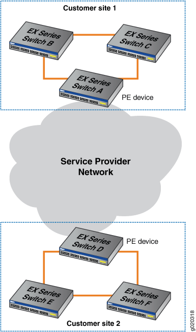
When you enable L2PT on a VLAN, you also must enable Q-in-Q tunneling. Q-in-Q tunneling ensures that Switches A, B, C, D, E, and F are part of the same broadcast domain.
This example uses STP as the Layer 2 protocol being tunneled,
but you could substitute any of the supported protocols for STP. You
can also use the all keyword to enable L2PT for all supported
Layer 2 protocols.
Tunneled Layer 2 PDUs do not normally arrive at a high rate. If the tunneled Layer 2 PDUs do arrive at a high rate, you might have a problem in the network. Typically, you would want to shut down the interface that is receiving a high rate of tunneled Layer 2 PDUs so that the problem can be isolated. Alternately, if you do not want to completely shut down the interface, you can configure the switch to drop tunneled Layer 2 PDUs that exceed a certain threshold.
The drop-theshold configuration statement enables
you to specify the maximum number of Layer 2 PDUs of the specified
protocol that can be received per second on the interfaces in a specified
VLAN before the switch begins dropping the Layer 2 PDUs. The
drop threshold must be less than or equal to the shutdown threshold.
If the drop threshold is greater than the shutdown threshold and you
try to commit the configuration, the commit will fail.
The shutdown-threshold configuration statement enables
you to specify the maximum number of Layer 2 PDUs of the specified
protocol that can be received per second on the interfaces in a specified
VLAN before the specified interface is disabled. The shutdown threshold
must be greater than or equal to the drop threshold. You can specify
a drop threshold without specifying a shutdown threshold, and you
can specify a shutdown threshold without specifying a drop threshold.
If you do not specify these thresholds, then no thresholds are enforced.
As a result, the switch tunnels all Layer 2 PDUs regardless of
the speed at which they are received, although the number of packets
tunneled per second might be limited by other factors.
In this example, we will configure both a drop threshold and a shutdown threshold to show how this is done.
If L2PT-encapsulated packets are received on an access interface, the switch reacts as it does when there is a loop between the service provider network and the customer network and shuts down (disables) the access interface.
Once an interface is disabled, you must explicitly reenable
it using the clear ethernet-switching layer2-protocol-tunneling
error command or else the interface will remain disabled.
Configuration
To configure L2PT, perform these tasks:
Procedure
CLI Quick Configuration
To quickly configure L2PT, copy the following commands and paste them into the switch terminal window of each PE device (in Figure 2, Switch A and Switch D are the PE devices):
[edit] set vlans customer-1 dot1q-tunneling set vlans customer-1 dot1q-tunneling layer2-protocol-tunneling stp set vlans customer-1 dot1q-tunneling layer2-protocol-tunneling stp drop-threshold 50 set vlans customer-1 dot1q-tunneling layer2-protocol-tunneling stp shutdown-threshold 100
Step-by-Step Procedure
To configure L2PT, perform these tasks on each PE device (in Figure 2, Switch A and Switch D are the PE devices):
Enable Q-in-Q tunneling on VLAN
customer-1:[edit] user@switch# set vlans customer-1 dot1q-tunneling
Enable L2PT for STP on VLAN
customer-1:[edit] user@switch# set vlans customer-1 dot1q-tunneling layer2-protocol-tunneling stp
Configure the drop threshold as 50:
[edit] user@switch# set vlans customer-1 dot1q-tunneling layer2–protocol-tunneling stp drop-threshold 50
Configure the shutdown threshold as 100:
[edit]
user@switch# set vlans customer-1 dot1q-tunneling layer2–protocol-tunneling stp shutdown-threshold 100
Results
Check the results of the configuration:
[edit]
user@switch# show vlans customer-1 dot1q-tunneling
layer2-protocol-tunneling {
    stp {
        drop-threshold 50;
        shutdown-threshold 100;
    }
}
Verification
To verify that L2PT is working correctly, perform this task:
Verify That L2PT Is Working Correctly
Purpose
Verify that Q-in-Q tunneling and L2PT are enabled.
Action
Check to see that Q-in-Q tunneling and L2PT are enabled on each PE device (Switch A and Switch D are the PE devices):
user@switchA> show vlans extensive customer-1
VLAN: customer–1, Created at: Thu Jun 25 05:07:38 2009
802.1Q Tag: 100, Internal index: 4, Admin State: Enabled, Origin: Static
Dot1q Tunneling status: Enabled
Layer2 Protocol Tunneling status: Enabled
Protocol: Port Mode, Mac aging time: 300 seconds
Number of interfaces: Tagged 0 (Active = 0), Untagged  3 (Active = 0)
      ge-0/0/7.0, untagged, access
      ge-0/0/8.0, untagged, access
      ge-0/0/9.0, untagged, access
Check to see that L2PT is tunneling STP on VLAN customer-1 and that drop-threshold and shutdown-threshold have been configured:
user@switchA> show ethernet-switching layer2-protocol-tunneling vlan customer-1

Layer2 Protocol Tunneling VLAN information:
VLAN          Protocol      Drop       Shutdown
                            Threshold  Threshold
customer–1    stp           50         100
Check the state of the interfaces on which L2PT has been enabled, including what kind of operation (encapsulation or decapsulation) they are performing:
user@switchA> show ethernet-switching layer2-protocol-tunneling interface

Layer2 Protocol Tunneling information:
Interface     Operation       State      Description
ge-0/0/0.0    Encapsulation   Shutdown   Shutdown threshold exceeded
ge-0/0/1.0    Decapsulation   Shutdown   Loop detected
ge-0/0/2.0    Decapsulation   Active
Meaning
The show vlans extensive customer-1 command
shows that Q-in-Q tunneling and L2PT have been enabled. The show
ethernet-switching layer2-protocol-tunneling vlan customer-1 command shows that L2PT is tunneling STP on VLAN customer-1,the drop threshold is set to 50, and the shutdown threshold is set
to 100. The show ethernet-switching layer2-protocol-tunneling
interface command shows the type of operation being performed
on each interface, the state of each interface and, if the state is Shutdown, the reason why the interface is shut down.
Platform-Specific L2PT Behavior
Use Feature Explorer to confirm platform and release support for specific features.
Use the following table to review platform-specific behavior for your platforms.
See the Additional Platform Information section for more information.
|
Platform |
Difference |
|---|---|
|
ACX Series (Junos OS Evolved) |
|
|
MX Series |
|
Additional Platform Information
Use Feature Explorer to confirm platform and release support for specific features.
Use the following sections to review platform-specific behaviors for your platforms.
ACX Series Routers
L2PT on ACX Series routers supports tunneling the Layer 2 PDUs listed in Table 1 with the indicated Ethernet encapsulation type and MAC address.
|
Protocol |
Ethernet Encapsulation |
MAC Address |
|---|---|---|
|
802.1X (IEEE 802.1X authentication) |
Ether (0x888E) |
01:80:C2:00:00:03 |
|
802.3ah (IEEE 802.3ah Operation, Administration, and Maintenance (OAM) link fault management (LFM)) |
Ether (0x8809) |
01:80:C2:00:00:02 |
|
Cisco Discovery Protocol (CDP) |
LLC (0xAAAA03) |
01:00:0C:CC:CC:CC |
|
Ethernet local management interface (E-LMI) |
Ether (0x88EE) |
01:80:C2:00:00:07 |
|
Link Aggregation Control Protocol (LACP) |
Ether (0x8809) |
01:80:C2:00:00:02 |
|
Link Layer Discovery Protocol (LLDP) |
Ether (0x88CC) |
01:80:C2:00:00:0E |
|
Multiple MAC Registration Protocol (MMRP) |
Ether (0x88F5) |
01:80:C2:00:00:20 |
|
MVRP VLAN Registration Protocol (MVRP) |
Ether (0x88F6) |
01:80:c2:00:00:21 |
|
Spanning Tree Protocol (STP), Rapid Spanning Tree Protocol (RSTP), and Multiple Spanning Tree Protocol (MSTP) |
LLC (0x424203) |
01:80:C2:00:00:00 |
|
VLAN Trunking Protocol (VTP) |
LLC (0xAAAA03) |
01:00:0C:CC:CC:CC |
MX Series Routers
MX Series routers that support this feature support tunneling the Layer 2 PDUs shown in Table 2.
|
Protocol |
MAC Address |
|---|---|
|
Cisco Discovery Protocol (CDP) |
01:00:0C:CC:CC:CC |
|
Per-VLAN Spanning Tree Protocol (PVSTP) |
01:00:0C:CC:CC:CD |
|
Spanning Tree Protocol (STP), Rapid Spanning Tree Protocol (RSTP), and Multiple Spanning Tree Protocol (MSTP) |
01:80:C2:00:00:00 |
|
VLAN Trunking Protocol (VTP) |
01:00:0C:CC:CC:CC |
L2PT and MAC rewrite are supported in VPLS, but only certain hardware configurations are supported. Table 3 shows the Modular Port Concentrators (MPCs) and enhanced Dense Port Concentrators (DPCs) supported when configuring L2PT and VPLS.
|
CE-Facing Interface |
PE-Core Facing Interface |
Layer 2 Protocol Tunneling |
|---|---|---|
|
MPC |
MPC |
Yes |
|
MPC |
Enhanced DPC |
Yes |
|
Enhanced DPC |
MPC |
Yes |
|
Enhanced DPC |
Enhanced DPC |
No |
All MPCs support L2PT. MX Series routers with certain enhanced DPCs or enhanced queuing DPCs support L2PT. See Table 4 for a list of the supported DPCs.
L2PT is not supported on Rev-A DPCs on MX Series routers because of microcode space limitations.
|
DPC Name |
DPC Model Number |
|---|---|
| Gigabit Ethernet | |
|
DPCE-R-40GE-SFP |
|
|
DPCE-X-40GE-SFP |
|
|
Gigabit Ethernet Enhanced Queuing Ethernet Services DPC with SFP |
DPCE-X-Q-40GE-SFP |
|
DPCE-R-Q-20GE-SFP |
|
|
DPCE-R-Q-40GE-SFP |
|
| 10-Gigabit Ethernet | |
|
DPCE-R-2XGE-XFP |
|
|
DPCE-R-4XGE-XFP |
|
|
DPCE-X-4XGE-XFP |
|
|
10-Gigabit Ethernet Enhanced Queuing Ethernet Services DPC with XFP |
DPCE-X-Q-4XGE-XFP |
|
10-Gigabit Ethernet Enhanced Queuing IP Services DPC with XFP |
DPCE-R-Q-4XGE-XFP |
| Multi-Rate Ethernet | |
|
DPCE-R-20GE-2XGE |
|
|
Multi-Rate Ethernet Enhanced Ethernet Services DPC with SFP and XFP |
DPCE-X-20GE-2XGE |
|
Multi-Rate Ethernet Enhanced Queuing IP Services DPC with SFP and XFP |
DPCE-R-Q-20GE-2XGE |
| Tri-Rate Ethernet | |
|
DPCE-R-40GE-TX |
|
|
DPCE-X-40GE-TX |
|
When a device sends a RADIUS access request, the Chargeable-User-Identity
parameter is an empty field. For more information about configuring RADIUS, see the
Junos Subscriber Access Configuration Guide.
EX Series and QFX Series Switches
QFX Series and EX Series switches that use the Enhanced Layer 2 Software (ELS) configuration style share the same configuration hierarchy to set up L2PT. The configuration hierarchy is different for EX Series switches that do not support ELS. Use Feature Explorer to check if your EX Series switch supports ELS.
For details on the configuration options to enable tunneling the supported protocols on each type of switch, see either of the following configuration statements:
-
QFX Series switches and EX Series ELS switches: protocol statement in the
[edit protocols layer2-control mac-rewrite interface
         interface-name]
hierarchy. -
Non-ELS switches: layer2-protocol-tunneling statement in the
[edit vlans
         vlan-name dot1q-tunneling]
hierarchy.
Table 5 lists the Layer 2 protocols that can be tunneled on QFX Series and EX Series switches. All switches that support L2PT can tunnel the listed protocols unless otherwise noted in the second column.
|
Layer 2 Protocol That Can Be Tunneled |
Support Notes and Exceptions |
|---|---|
|
802.1X authentication |
Not supported on EX2300 multigigabit model switches. |
|
802.3ah Operation, Administration, and Maintenance (OAM) link fault management (LFM) |
If you enable L2PT for untagged OAM LFM packets, do not configure LFM on the corresponding access interface. |
|
Cisco Discovery Protocol (CDP) |
You can’t configure CDP on EX Series and QFX Series switches. However, L2PT can tunnel CDP PDUs. |
|
Ethernet local management interface (E-LMI) |
Not supported on EX2300 multigigabit model switches. |
|
Generic Attribute Registration Protocol (GARP) VLAN Registration Protocol (GVRP) |
Supported. |
|
Link Aggregation Control Protocol (LACP) |
If you enable L2PT for untagged LACP packets, do not configure Link Aggregation Control Protocol (LACP) on the corresponding access interface. |
|
Link Layer Discovery Protocol (LLDP) |
Supported. |
|
Multiple MAC Registration Protocol (MMRP) |
Not supported on EX2300 multigigabit model switches. |
|
MVRP VLAN Registration Protocol (MVRP) |
Supported. |
|
Per-VLAN Spanning Tree and Per-VLAN Spanning Tree Plus (PVST+) Protocols |
Only supported on EX9200 switches. Use this option to enable tunneling VSTP instead of the |
|
Spanning Tree Protocol (STP), Rapid Spanning Tree Protocol (RSTP), and Multiple Spanning Tree Protocol (MSTP) |
Supported. |
|
Unidirectional Link Detection (UDLD) |
Not supported on EX2300 multigigabit model switches. You can’t configure UDLD on EX Series and QFX Series switches. However, L2PT can tunnel UDLD PDUs. |
|
VLAN Spanning Tree Protocol (VSTP) |
EX9200 switches support tunneling VSTP packets but do not have a separate option to
enable tunneling VSTP. The option that enables tunneling PVST and PVST+
( |
|
VLAN Trunking Protocol (VTP) |
You can’t configure VTP on EX Series and QFX Series switches. However, L2PT can tunnel VTP PDUs. |
The egress PE switches use the encapsulated MAC address to identify the tunneled Layer 2 control protocol and do the destination MAC address rewrite. Table 6 lists the supported protocols and their corresponding encapsulation types and MAC addresses on EX Series and QFX Series switches:
|
Protocol |
Ethernet Encapsulation |
MAC Address |
|---|---|---|
|
802.1X |
Ether-II |
01:80:C2:00:00:03 |
|
802.3ah |
Ether-II |
01:80:C2:00:00:02 |
|
CDP |
LLC/SNAP |
01:00:0C:CC:CC:CC |
|
E-LMI |
Ether-II |
01:80:C2:00:00:07 |
|
GVRP |
LLC/SNAP |
01:80:C2:00:00:21 |
|
LACP |
Ether-II |
01:80:C2:00:00:02 |
|
LLDP |
Ether-II |
01:80:C2:00:00:0E |
|
MMRP |
Ether-II |
01:80:C2:00:00:20 |
|
MVRP |
Ether-II |
01:80:C2:00:00:21 |
|
PVSTP |
LLC/SNAP |
01:00:0C:CC:CC:CD |
|
STP, RSTP, MSTP |
LLC/SNAP |
01:80:C2:00:00:00 |
|
UDLD |
LLC/SNAP |
01:00:0C:CC:CC:CC |
|
VSTP |
LLC/SNAP |
01:00:0C:CC:CC:CD |
|
VTP |
LLC/SNAP |
01:00:0C:CC:CC:CC |
Change History Table
Feature support is determined by the platform and release you are using. Use Feature Explorer to determine if a feature is supported on your platform.
l2circuit-control-passthrough
configuration statement under the forwarding-options hierarchy level to allow
tunneling to remote PE. This configuration statement is no-longer needed and the option is
removed from configuration hierarchy. We’ve implemented this feature per “MEF 6.1.1 Layer 2
Control Protocol Handling Amendment.”