PWHT Pseudowire over Aggregated Ethernet
Pseudowire Headend Termination (PWHT) over Aggregated Ethernet (PS over AE or PSoAE) is used to eliminate the loopback penalty that exists with PWHT pseudowire configurations on Logical Tunnels (LT) and Redundant Logical Tunnels (RLT).
PWHT Pseudowire over Aggregated Ethernet Overview
Overview
When you deploy Pseudowire Headend Termination (PWHT) over Aggregated Ethernet (PS over AE), you anchor PWHT pseudowire interfaces directly on access Aggregated Ethernet (AE) interfaces. This design removes logical tunnel (LT) and redundant logical tunnel (RLT) loopback recirculation and collapses downstream processing into a single Packet Forwarding Engine (PFE) pass. Both upstream and downstream traffic associated with a given PS interface needs to pass through the access AE interface on which the PS is anchored.
AE targeting or load-balancing determines which Access AE member link carries traffic for a PS service IFL. The anchor PFE is implicitly selected based on the PFE hosting that member link. This selection determines class of service (CoS) shaping precision, policing behavior, and Connectivity Fault Management (CFM) anchoring.
PS over AE supports Layer 2 and Layer 3 PWHT services, including unicast, multicast, virtual private LAN service (VPLS), Ethernet VPN (EVPN), and EVPN–virtual private wire service (EVPN‑VPWS) headend termination.
CoS, firewall filters and policers, CFM down maintenance association end points (Down MEPs), Bidirectional Forwarding Detection (BFD), port mirroring, Inline Jflow, Flowtap‑lite, and standard telemetry operate in parity with PS over LT/RLT, subject to encapsulation, maximum transmission unit (MTU), CoS, and AE constraints.
Benefits of PS over AE
-
Eliminates downstream loopback recirculation over LT/RLT, which reduces fabric and WAN bandwidth consumption and removes the additional latency and processing overhead of a second PFE pass.
-
Simplifies downstream CoS design by using a single scheduler hierarchy on the access AE member, making it easier to determine shaping, queuing, and bandwidth allocation for PWHT and non‑PWHT traffic.
-
Provides deterministic CoS and policing behavior when you use targeting, because each PS service IFL is tied to a specific AE member link and anchor PFE. This association allows configured shaping and policer rates to closely match actual traffic rates.
-
Extends PWHT loopback‑free operation to both Layer 2 and Layer 3 services, including multicast, VPLS/EVPN, and EVPN‑VPWS headend termination, so that a wide range of service types benefit from the single‑pass data path and AE‑based anchoring.
-
Preserves operational consistency with existing PWHT over LT/RLT implementations by reusing the same management, BFD, CFM, telemetry, and service tooling, which reduces the learning curve and simplifies migration between deployment models.
Configuring PS over AE
Configuring PS over AE is similar to PS over LT/RLT; however, the Access AE interface is assumed to already exist. Instead of configuring logical tunnels, you anchor PS on access AE interfaces. There are a few things to keep in mind:
-
The PS IFD must be anchored on a tagged AE IFD. You configure
vlan-taggingorflexible-vlan-taggingto channelize the device.Note: If the anchoring AE IFD is not a tagged device, a commit error will be thrown. -
The PS interface must be deactivated before you change the anchor AE IFD.
Important: While your PS IFD is anchored on your access AE interface, the underlying AE IFD cannot be disabled. An error will be thrown when you attempt to commit the configuration.
Traffic Behavior for PS over AE
Downstream Behavior
Downstream traffic no longer recirculates through an LT. Instead, it bypasses the AE IFL selector on the anchor PFE and uses the child link ID that the system chooses at ingress to drive egress on the selected AE member link. This single-pass design removes the loopback penalty and simplifies accounting.
PS and non-PS traffic share the same AE member hierarchy, with:
-
PS traffic shaped by PS IFL queues.
-
Non-PS traffic shaped by AE IFL queues.
Because the system replicates PS IFL shapers per AE member, when you use load-balancing, each member receives the full configured PS IFL rate and aggregate throughput can exceed the nominal shaping rate. Only targeted operation yields precise shaping and policing.
Upstream Behavior
Upstream behavior is closer to the traditional model, but targeting still materially changes your policing guarantees.
With targeting:
-
When you target a PS IFL to a specific distribution list that maps to a single AE member, you steer all upstream traffic for that service to the anchor PFE.
-
A single policer instance on the PS service IFL can enforce the configured rate accurately.
Without targeting:
-
Traffic from a customer edge (CE) device can arrive on any AE member.
-
Traffic can be distributed across PFEs and policed independently on each member.
-
Aggregate rates can exceed configured limits.
The same targeting logic also drives CFM anchoring. Down MEPs that you configure on PS IFLs bind to the PFE that hosts the targeted member and re-anchor only when you change targeting lists or remove the anchor Flexible PIC Concentrator (FPC). This behavior provides predictable operations, administration, and maintenance (OAM) behavior tied to your AE design. See PS over AE Targeting and Load Balancing Modes for more information.
Single-Pass (PS over AE) vs Double-Pass (PS over LT/RLT) Operations
PS over AE configurations eliminate the LT/RLT interface from the PWHT PS configuration. CoS functions are achieved in a single pass rather than a double pass. This reduces bandwidth overhead and resource usage by a significant amount compared to PS over LT/RLT configurations. Table 1 shows the differences between Single-Pass and Double-Pass operations.
|
Aspect |
Single-Pass (PS over AE) |
Double-Pass (PS over LT/RLT) |
|---|---|---|
|
CoS hierarchy |
Achieved in the egress handover |
Requires loopback |
|
Loopback Tunnel |
Eliminated |
Required; packets recirculated via loopback stream to enable CoS shaping and encapsulation |
|
LUSS Processing |
Packet processed once - PS service egress, PS transport ingress, and WAN egress combined |
Packet processed twice - once at egress LT and once at egress WAN access port |
|
PFE locality |
PS interface and access WAN interface must be on the same anchor PFE |
PS interface and access WAN interface can be on different PFEs |
|
Shaping |
Applied by XQSS in single pass |
Applied during second pass after loopback |
PS over AE Targeting and Load Balancing Modes
PS over AE Targeting Mode
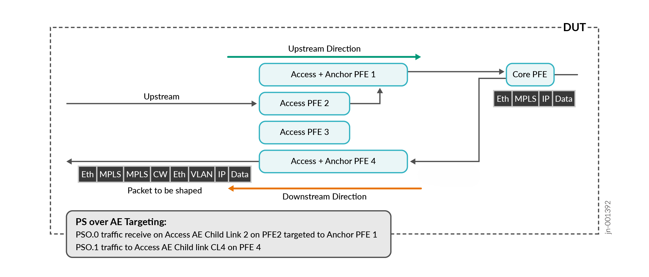
In targeted mode, PS over Aggregated Ethernet sends traffic through specified child links in the aggregated Ethernet bundle. Targeted mode allows for precise CoS features by mapping traffic to a distribution-list with only one AE member. Redundancy is provided by the use of primary and backup distribution lists.
Precise shaping and policing requires targeting mode. For example, in a configuration with a 100 mbps policer on the PS interface and two AE member links that are also configured at 100 mbps, the targeted interface in the primary-list will be limited by the policer's configured traffic rate of 100 mbps.
To configure Targeting Mode, you use the targeted-distribution command to specify
which primary and backup distribution lists the interface will use for traffic
distribution.
targeted-options command to type manual
under the ps interface configuration to achieve this.Figure 1 shows a diagram of PS over AE Targeting Mode.
PS over AE Load-Balancing Mode (Without Targeting)
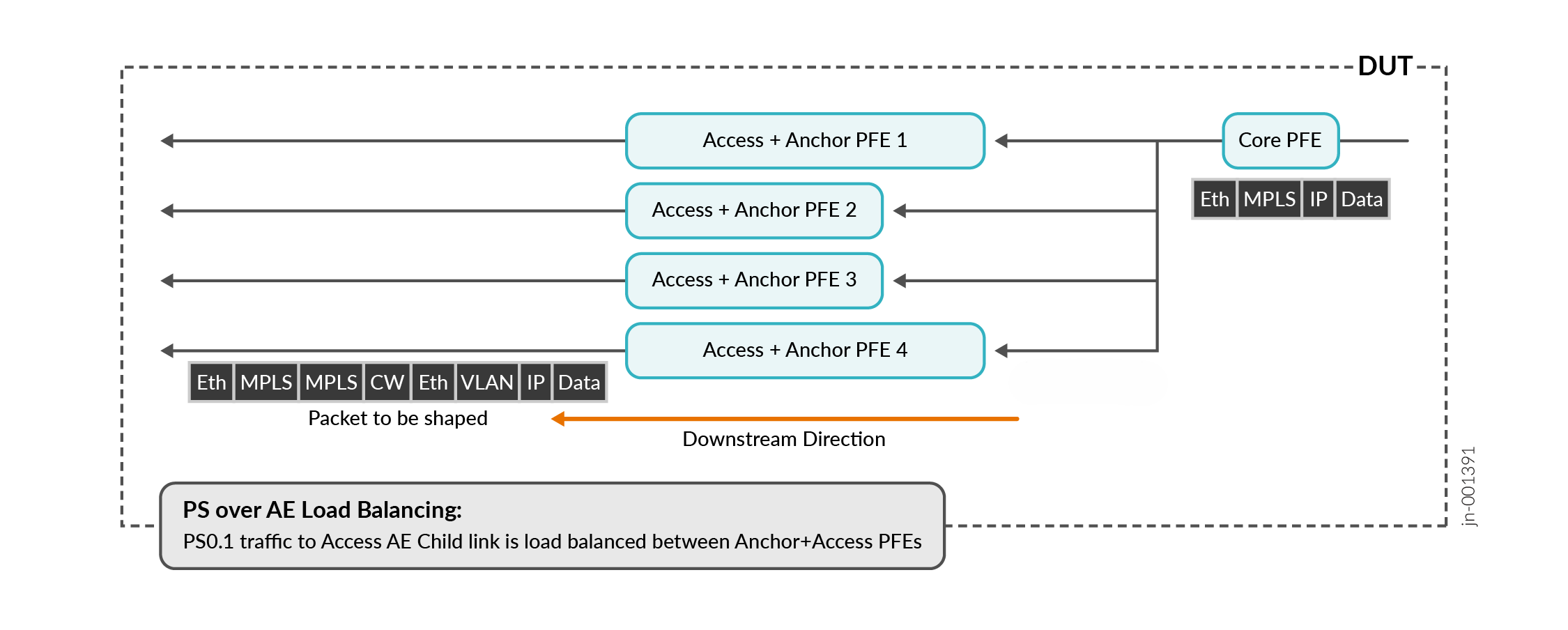
In load balancing mode, traffic proceeds through the Aggregated Ethernet bundle and is balanced across all child links. Load balancing occurs if targeting mode is not used.
Load balancing mode results in imprecise ingress or egress policing, as the policer will allow more traffic than the configuration specifies. For example, in a configuration with a 100 mbps policer on the ps interface and two AE member links that are also configured at 100 mbps, the policer would allow each link to pass 100 mbps instead of a total of 100 mbps across all links.
Figure 2 shows a diagram of PS over AE Load Balancing Mode without Targeting.
Class of Service and Hierarchical Class of Service for PS over AE
Class of Service Differences in PS over AE
There are several differences in behavior and configuration for PS over AE.
-
Shaping
-
A shaper at the access AE IFL will shape only non-PS interface traffic. The PS and AE interface scheduler nodes are mutually exclusive.
-
-
Shaper Application
-
A shaper applied on the AE IFD applies to all traffic passing through the access AE interface (AE IFL and PS IFL).
-
-
Shaping Rate Overhead
-
Shaping occurs after MPLS pseudowire header is added for the access network.
-
You use Overhead Accounting or Egress Shaping Overhead commands to adjust.
-
-
Hierarchical CoS for PS over AE
PS over AE requires Hierarchical CoS configuration on the WAN access AE interface. You use the scheduler-map within the Traffic Control Profile for the WAN Access AE interface. See Example: Configuring Hierarchical CoS for PS over AE for more information.
Example: Configuring Hierarchical CoS for PS over AE
PWHT pseudowire over Aggregated Ethernet requires HCoS configuration on the WAN access AE interface.
Configure the hierarchical scheduler on the AE interface you will use.
user@host# set interfaces aeinterface-number hierarchical-scheduler implicit-hierarchy
This command establishes the required two-level scheduling hierarchy that PS over AE requires. Using
implicit-hiearchyautomatically creates the structure without requiring explicit queue configuration.Apply the scheduler-map on the Traffic Control Profile.
user@host# set class-of-service traffic-control-profiles profile name scheduler-map map-name
This creates a Traffic Control Profile to encapsulate the scheduler map configuration. When HCoS is enabled, scheduler maps cannot be applied directly to the physical interface and must be contained within a Traffic Control Profile.
Apply the Output Traffic Control Profile to the AE physical interface (IFD).
user@host# set class-of-service interfaces aeinterface-number output-traffic-control-profile profile-name
This command enables aggregated bandwidth control at the physical interface, ensuring total bandwidth across all logical interfaces (AE IFLs and PS IFLs) does not exceed the physical interface capacity.
Apply the Output Traffic Control Profile to the AE logical interface.
user@host# set class-of-service interfaces aeinterface-number unit unit-number output-traffic-control-profile profile name
When you apply the Output Traffic Control Profile to the logical interface unit (IFL), per-service bandwidth management and schduling policies are activated. A shaper applied at the WAN access AE IFL will shape only non-PS interface traffic. The PS IFL and AE IFL scheduler nodes are mutually exclusive at the same level under the same IFD.
Apply an Output Traffic Control Profile to the PS Transport IFL, Service IFL, or both. You use the same command,
user@host# set class-of-service interfaces psinterface-number unit unit-number output-traffic-control-profile profile name
PS over AE supports the Output Traffic Control Profile applied to the PS Transport IFL, the Service IFL, or both. The shapers at the PS Transport IFL and the Service IFL provide multi-level shaping. PS traffic is shaped by PS IFL queues, not by the AE IFL.
Configure overhead accounting for MPLS headers.
user@host# set class-of-service traffic-control-profiles profile-name overhead-accounting bytes byte-value
This ensures shaping calculations also account for protocol overhead added after shaping decisions.
Configure hardware level egress shaping overhead.
user@host# set chassis fpc fpc-number pic pic-number traffic-manager egress-shaping-overhead byte-value
When both overhead-accounting and egress-shaping-overhead are configured, the total byte adjustment equals the sum of both values.