Color-Based Traffic Engineering Configuration
BGP Classful Transport Planes Overview
- Benefits of BGP Classful Transport Planes
- Terminology of BGP Classful Transport Planes
- Understanding BGP Classful Transport Planes
- Intra-AS Implementation of BGP Classful Transport Planes
- Inter-AS Implementation of BGP Classful Transport Planes
Benefits of BGP Classful Transport Planes
-
Network-slicing–Service and transport layers are decoupled from each other, laying the foundation for network-slicing and virtualization with the end-to-end slicing across multiple domains, thereby significantly reducing the CAPEX.
- Inter-domain interoperability–Extends transport class deployment across co-operating domains so the different transport signaling protocols in each domain interoperate. Reconciles any differences between extended community namespaces that may be in use in each domain.
-
Colored resolution with fallback–Enables resolution over colored tunnels (RSVP, IS-IS flexible algorithm) with flexible fallback options over best-effort tunnels or any other color tunnel.
- Quality-of-service–Customizes and optimizes the network to achieve the end-to-end SLA requirements.
- Leveraging existing deployments–Supports well deployed tunneling protocols like RSVP along with new protocols, such as IS-IS flexible algorithm, preserving ROI and reducing OPEX.
Terminology of BGP Classful Transport Planes
This section provides a summary of commonly used terms for understanding BGP classful transport plane.
-
Service node–Ingress Provider Edge (PE) devices that send and receive service routes (Internet and Layer 3 VPN).
-
Border node–Device at the connection point of different domains (IGP areas or ASs).
-
Transport node–Device that sends and receives BGP-Labeled Unicast (LU) routes.
-
BGP-VPN–VPNs built using RFC4364 mechanisms.
-
Route Target (RT)–Type of extended community used to define VPN membership.
-
Route Distinguisher (RD)–Identifier used to distinguish to which VPN or virtual private LAN service (VPLS) a route belongs. Each routing instance must have a unique route distinguisher associated with it.
- Resolution scheme–Used to resolve protocol next-hop address (PNH) in resolution
RIBs providing fallback.
They map the routes to the different transport RIBs in the system based on mapping community.
-
Service family–BGP address family used for advertising routes for data traffic, as opposed to tunnels.
-
Transport family –BGP address family used for advertising tunnels, which are in turn used by service routes for resolution.
-
Transport tunnel–A tunnel over which a service may place traffic, for example, GRE, UDP, LDP, RSVP, SR-TE, BGP-LU.
-
Tunnel domain–A domain of the network containing service nodes and border nodes under a single administrative control that has a tunnel between them. An end-to-end tunnel spanning several adjacent tunnel domains can be created by stitching the nodes together using labels.
-
Transport class–A group of transport tunnels offering the same type of service.
Transport class RT–A new format of route target used to identify a specific transport class.
A new format of Route Target used to identify a specific transport class.-
Transport RIB–At the service node and border node, a transport class has an associated transport RIB that holds its tunnel routes.
-
Transport RTI–A routing instance; container of transport RIB, and associated transport class Route Target and Route Distinguisher.
-
Transport plane–Set of transport RTIs importing same transport class RT. These are in turn stitched together to span across tunnel domain boundaries using a mechanism similar to Inter-AS option-b to swap labels at border nodes (nexthop-self), forming an end-to-end transport plane.
-
Mapping community–Community on a service route that maps to resolve over a transport class.
Understanding BGP Classful Transport Planes
You can use BGP classful transport planes to configure transport classes for classifying a set of transport tunnels in an intra-AS network based on the traffic engineering characteristics and use these transport tunnels to map service routes with the desired SLA and intended fallback.
BGP classful transport planes can extend these tunnels to inter-domain networks that span across multiple domains (ASs or IGP areas) while preserving the transport class. To do this, you must configure the BGP classful transport transport layer BGP family between the border and service nodes.
In both inter-AS and intra-AS implementations, there can be many transport tunnels (MPLS LSPs, IS-IS flexible algorithm, SR-TE) created from the service and border nodes. The LSPs may be signaled using different signaling protocols in different domains, and can be configured with different traffic engineering characteristics (class or color). The transport tunnel endpoint also acts as the service endpoint and can be present in the same tunnel domain as the service ingress node, or in an adjacent or non-adjacent domain. You can use BGP classful transport planes to resolve services over LSPs with certain traffic engineering characteristics either inside a single domain or across multiple domains.
BGP classful transport planes reuse the BGP-VPN technology, keeping the tunneling-domains loosely coupled and coordinated.
- The network layer reachability information (NLRI) is RD:TunnelEndpoint used for path-hiding.
- The route target indicates the transport class of the LSPs, and leaks routes to the corresponding transport RIB on the destination device.
- Every transport tunneling protocol installs an ingress route into the transport-class.inet.3 routing table, models the tunnel transport class as a VPN route target, and collects the LSPs of the same transport class in the transport-class.inet.3 transport-rib routing table.
-
Routes in this routing instance are advertised in the BGP classful transport plane (inet transport) AFI-SAFI following procedures similar to RFC-4364.
-
When crossing inter-AS link boundary, you must follow Option-b procedures to stitch the transport tunnels in these adjacent domains.
Similarly, when crossing intra-AS regions you must follow Option-b procedures to stitch the transport tunnels in the different TE-domains.
-
You can define resolution schemes to specify the intent on the variety of transport classes in a fallback order.
- You can resolve service routes and BGP classful transport routes over these transport classes, by carrrying the mapping community on them.
The BGP classful transport family runs along side the BGP-LU transport layer family. In a seamless MPLS network running BGP-LU, meeting stringent SLA requirements of 5G is a challenge as the traffic engineering characteristics of the tunnels are not known or preserved across domain boundaries. BGP classful transport planes provide operationally easy and scalable means to advertise multiple paths for remote loopbacks along with the transport class information in the seamless MPLS architecture. In BGP classful transport family routes, different SLA paths are represented using Transport Route-Target extended community, which carries the transport class color. This Transport Route-Target is used by the receiving BGP routers to associate the BGP classful transport route with the appropriate transport class. When re-advertising the BGP classful transport routes, MPLS swaps routes, inter connect the intra-AS tunnels of the same transport class, thereby forming an end-to-end tunnel that preserves the transport class.
Intra-AS Implementation of BGP Classful Transport Planes
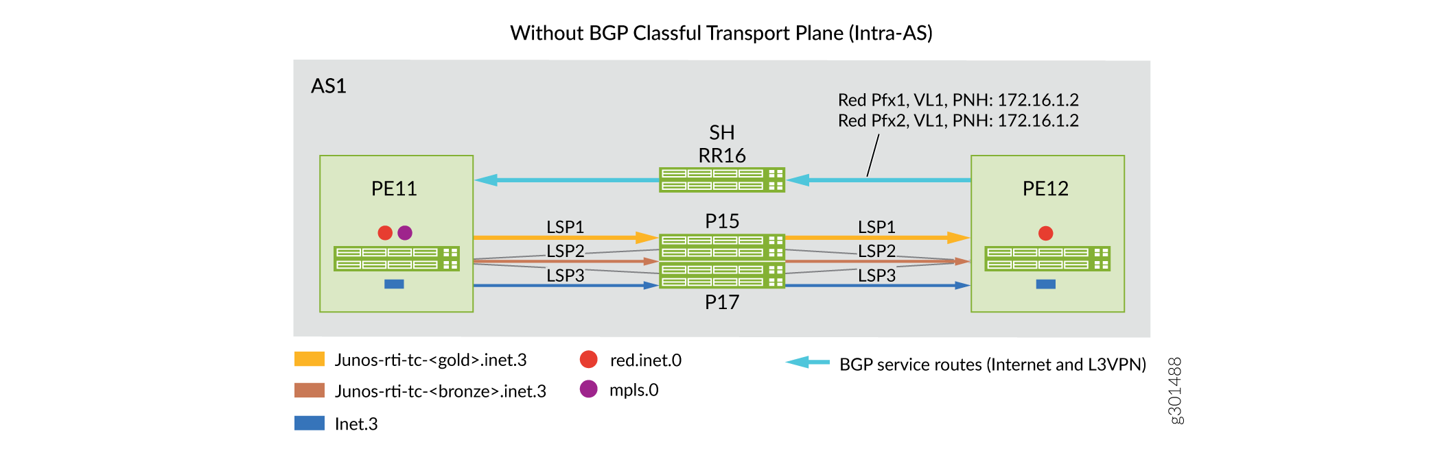
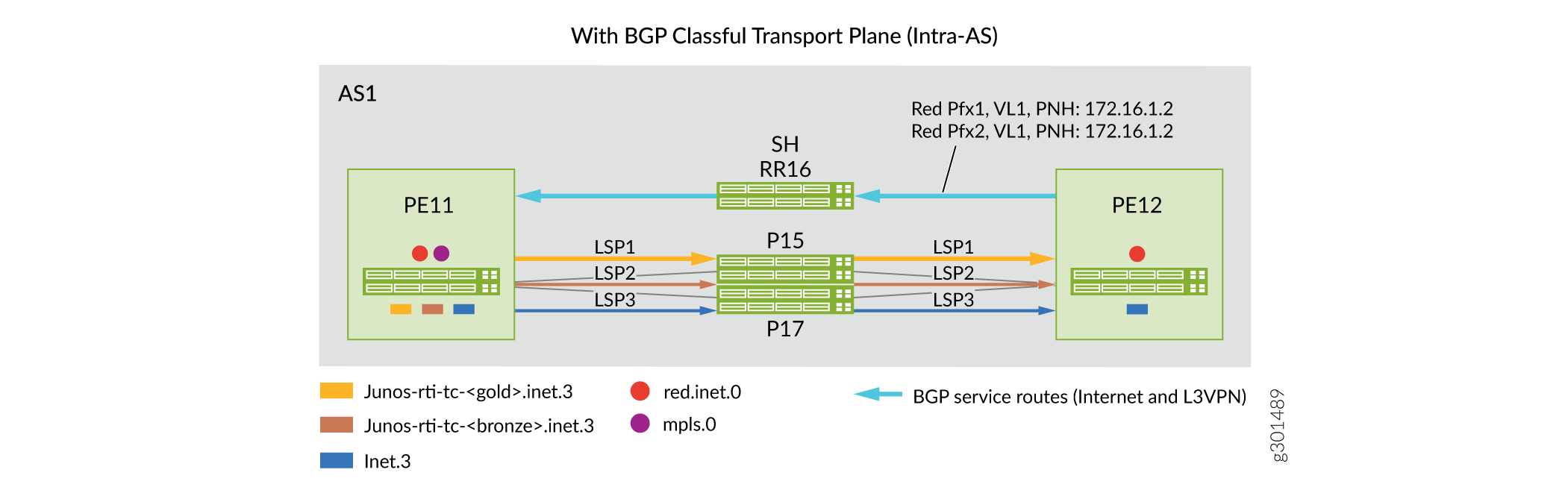
Figure 1 illustrates a network topology with before-and-after scenarios of implementing BGP classful transport planes in an intra-AS domain. Devices PE11 and PE12 use RSVP LSPs as the transport tunnel and all transport tunnel routes are installed in inet.3 RIB. Implementing BGP classful transort planes enables RSVP transport tunnels to be color-aware similar to segment routing tunnels.
To classify transport tunnels into BGP transport class in an intra-AS setup:
- Define the transport class at the service node (ingress PE devices), for example, gold
and bronze, and assign color community values to the defined transport class.
Sample configuration:
pe11# show routing-options route-distinguisher-id 172.16.1.1; transport-class { name gold { color 100; } name bronze { color 200; - Associate the transport tunnel to a specific transport class at the ingress node of the
tunnels.
Sample configuration:
pe11# show protocols mpls
label-switched-path toPE12-bronze {
    transport-class bronze;
}
label-switched-path toPE12-gold {
    transport-class gold;
}
Intra-AS BGP classful transport plane functionality:
- BGP classful transport creates predefined transport RIBs per named transport class (gold and bronze) and auto derives mapping community from its color value (100 and 200).
- Intra-AS transport routes are populated in transport RIBs by the tunneling protocol when
it is associated with a transport class.
In this example, RSVP LSP routes associated with transport class gold (color 100) and transport class bronze (color 200) are installed in the transport RIBs junos-rti-tc-<100>.inet.3 and junos-rti-tc-<200>.inet.3, respectively.
- Service node (ingress PEs) match extended color community (color:0:100 and color:0:200) of service route against the mapping community in predefined resolution RIBs and resolve the protocol next hop (PNH) in corresponding transport RIBs (either junos-rti-tc-<100>.inet.3, or junos-rti-tc-<200>.inet.3).
- BGP routes bind to a resolution scheme by carrying the assiocaited mapping community.
- Each transport class automatically creates two predefined resolution schemes and
automatically derives the mapping community.
One resolution scheme is for resolving service routes that use Color:0:<val> as the mapping community.
The other resolution scheme is for resolving transport routes that use Transport-Target:0:<val> as the mapping community.
- If service route PNH cannot be resolved using RIBs listed in the predefined resolution scheme, then it can fall back to the inet.3 routing table.
- You can also configure fallback between different colored transport RIBs by using user-defined resolution schemes under the [edit routing-options resolution scheme] configuration hierarchy.
Inter-AS Implementation of BGP Classful Transport Planes
In an inter-AS network, BGP-LU is converted to BGP classful transport network after configuring a minimum of two transport classes (gold and bronze) on all service nodes or PE devices and border nodes (ABRs and ASBRs).
To convert the transport tunnels into BGP classful transport:
- Define transport class at the service nodes (ingress PE devices) and the border nodes
(ABRs and ASBRs), for example, gold and broze.
Sample configuration:
pe11# show routing-options route-distinguisher-id 172.16.1.1; transport-class { name gold { color 100; } name bronze { color 200; - Associate the transport tunnels to a specific transport class at the ingress node of the
tunnels (ingress PEs, ABRs,and ASBRs).
Sample configuration:
For RSVP LSPs
abr23# show protocols mpls
label-switched-path toASBR21-bronze {
    transport-class bronze;
}
label-switched-path toASBR22-gold {
    transport-class gold;
For IS-IS flxible algorithm
asbr13# show routing-options flex-algorithm 128 { … color 100; use-transport-class; } flex-algorithm 129 { … color 200; use-transport-class; } - Enable new family for the BGP classful transport (inet transport) and BGP-LU (inet
labeled-unicast) in the network.
Sample configuration:
abr23# show protocols bgp group toAs2-RR27 { family inet { labeled-unicast { … } transport { … } cluster 172.16.2.3; neighbor 172.16.2.7; } - Advertise service routes from the egress PE device with appropriate extended color
community.
Sample configuration:
pe11# show policy-options policy-statement red
term 1 {
        from {
            route-filter 192.168.3.3/32 exact;
        }
        then {
            community add map2gold;
            next-hop self;
            accept;
        }
    }
    term 2 {
        from {
            route-filter 192.168.33.33/32 exact;
        }
        then {
            community add map2bronze;
            next-hop self;
            accept;
        }
    }
community map2bronze members color:0:200;
community map2gold members color:0:100;
Inter-AS BGP classful transport plane functionality:
- BGP classful transport planes create predefined transport RIBs per named transport class (gold and bronze) and automatically derives mapping community from its color value.
-
Intra-AS transport routes are populated in transport RIBs by tunneling protocols when associated with a transport class.
For example, transport tunnel routes associated with the transport class gold and bronze are installed in the transport RIBs junos-rti-tc-<100>.inet.3 and junos-rti-tc-<200>.inet.3, respectively.
- BGP classful transport planes use unique Route Distinguisher and Route Target when it copies the transport tunnel routes from each transport RIB to the bgp.transport.3 routing table.
- Border nodes advertise routes from bgp.transport.3 routing table to its peers in other domains if family inet transport is negotiated in the BGP session.
- Receiving border node installs these bgp-ct routes in the bgp.transport.3 routing table and copies these routes based on the transport Route Target to the appropriate transport RIBs.
- Service node matches the color community in the service route against a mapping community in the resolution schemes and resolves PNH in the corresponding transport RIB (either junos-rti-tc-<100>.inet.3, or junos-rti-tc-<200>.inet.3).
- Border nodes use predefined resolution schemes for transport route PNH resolution.
- Predefined or user defined, both resolution schemes support service route PNH resolution. Predefined uses inet.3 as fallback, and user-defined resolution scheme allows list of transport RIBs to be used in the order specified while resolving PNH.
- If service route PNH cannot be resolved using RIBs listed in the user-defined resolution scheme, then route is discarded.
Example: Configuring Classful Transport Planes (Intra-Domain)
- Before You Begin
- Functional Overview
- Topology Overview
- Topology Illustrations
- PE1 Configuration Steps
- Verify Classful Transport Planes
- Appendix 1: Troubleshooting
- Appendix 2: Set Commands on All Devices
- Appendix 3: Show Configuration Output on PE1
Before You Begin
| Hardware and Software requirements |
Junos OS Release 21.1R1 or later. Note:
Only the provider edge routers (PE1 and PE2) require Junos OS Release support for the BGP-CT feature. |
|
Estimated reading time |
45 minutes |
|
Estimated configuration time |
1 hour |
|
What to expect? |
A working BGP-CT network with three service levels that map to diversely routed LSP paths. A Junos configuration that maps specific traffic (VPN customer routes) to the desired transport class using BGP color attribute extended communities. Basic LSP traffic engineering to force traffic classes on to diverse paths in the provider network |
|
Business impact |
Use this configuration example to configure and verify the BGP Classful Transport (BGP-CT) feature within a single autonomous network (intra-domain). BGP-CT maps customer routes to network paths that can be engineered to provide varying levels of performance. A typical use case for intra-domain BGP-CT is for a service provider to deploy BGP-CT to offer tiered VPN service levels to their customers. |
|
Useful resources: |
|
|
Know more |
To better understand BGP-CT, see BGP Classful Transport Planes Overview |
|
Juniper vLabs |
Visit the Juniper virtual labs (vLabs) to reserve a pre-configured sandbox. Use the sandbox to interact with and understand the BGP-CT feature. You'll find the "Classful Transport Planes (Intra-Domain Scenario)" demonstration in the routing section . |
|
Learn more |
Junos Class of Service (JCOS) On-Demand |
Functional Overview
Table 1 provides a quick summary of the configuration components deployed in this example.
|
Routing and Signaling protocols |
|
|
OSPF |
All routers run OSPF as the IGP. All routers belong to area 0 (also called the backbone area). The single OSPF routing domain provides loopback connectivity in the provider network. |
|
Internal and External BGP |
The customer edge (CE) devices use EBGP peering to exchange routes with their provider edge device as part of a Layer 3 VPN service. The PE devices use IBGP to exchange IPv4 Layer 3 VPN routes with the remote PE. These routes also carry a color community used to map traffic to the correct data plane tunnel. Our example does not use a route reflector, instead opting for direct PE-PE peering. Note:
The provider router (P router) does not run BGP. Its part of a BGP-free core to promote scaling. The P device uses MPLS label based switching to transport the customer VPN traffic between the PE devices. |
|
RSVP |
Each PE devices signals three LSPs to the remote PE. These LSPs map to the corresponding service classes of gold, bronze, and Best-Effort (BE). RSVP supports rich traffic engineering to force traffic onto desired paths in the provider network. These paths can in turn be engineered to provide varying Class of Service (CoS) handling need to enforce the SLA for each transport class. Our basic topology provides three paths between the PE devices. We use a named path with an ERO to ensure diverse routing of the LSPs over the core. Junos supports a rich set of capabilities for traffic engineering. Note:
The classful transport feature is also supported with LSPs established through segment routing–traffic engineering (SR-TE) and IS-IS flex-algorithm tunnels. |
|
MPLS |
The provider network uses a MPLS based label switching data plane. The use of MPLS with TE paths ensures that each service class can be routed over disjoint paths with the desired performance levels. As noted above, MPLS also provides support for a BGP-free core. |
| Transport tunnels | |
|
Three MPLS tunnels (LSPs) are established between the PE devices: |
Each tunnel is assigned to the following transport classes:
|
| Service family | |
|
Layer 3 VPN ( |
BGP-CT also works with other service families, such as BGP labeled Unicast, Flowspec, or Layer 2 VPN. |
| Primary verification tasks | |
|
Verify working of IGP, RSVP, MPLS, BGP, and L3VPN. |
|
Modify the network to effect traffic steering between transport class tunnels to simulate the failure of a service tunnel and subsequent fail over to the BE path/class. |
Topology Overview
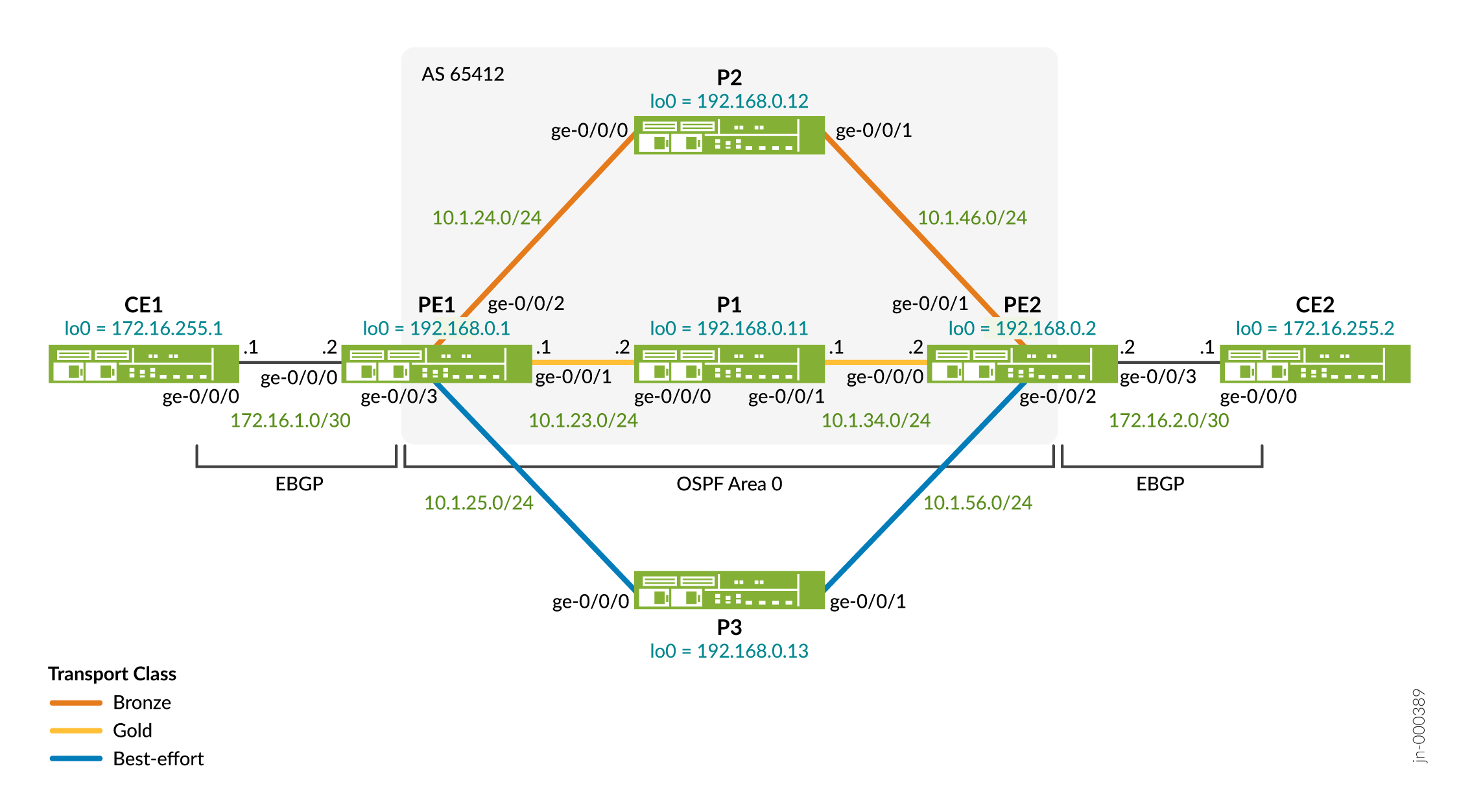
This configuration example is based on a simple MPLS-Based Layer 3 VPN with two customer edge (CE) devices that communicate over the service provider network. The network core has three provider (P) routers that transport the VPN customer traffic using labeled-based switching. The two provider edge (PE) devices provide a Layer 3 VPN service to their attached CEs. The PEs use RSVP signaled MPLS LSPs to transport VPN traffic over the core. See Example: Configure a Basic MPLS-Based Layer 3 VPN for background information on the operation and configuration of a MPLS-based L3VPN.
We focus on the left to right flow of traffic from CE1 to CE2, and how PE1 uses a BGP color community attached to routes learned from PE2 to map traffic sent to the remote CE over the desired LSP forwarding next hops. In our example, PE1 uses explicit route objects (ERO) to force the routing of these LSPs over diverse paths. We skip this step at PE2, allowing the LSPs to be routed based on IGP load balancing. In order to have traffic flow from CE1 to CE2, CE1 must have a route to reach CE2. The routes for CE2 travel in the opposite direction of the traffic it attracts from CE1. That is, the route to CE2's loopback travels from right to left.
In our example, the gold service class LSP is constrained to the PE1-P1-PE2 path. The bronze service class uses the PE1-P2-PE2 path. The best-effort LSP is routed along the PE1-P3-PE2 path. The topology diagram uses colored links to represent the three paths.
In our example, we add the protocols mpls icmp-tunneling statement.
This is to allow the CE devices to trace the path through the provider network, even
when that path involves MPLS switching as is the case for the Layer 3 VPN traffic.
This option helps you confirm the expected forwarding path as a function of
transport class is used.
Table 2 describes the role and functionality of each device in the context of this topology. Click on any device name to view its quick configuration.
| Device Name |
Role |
Function |
| CE1 | Local CE device (R1) . | EBGP peer to PE1 router to advertise and learn CE device loopback addresses. Test service connectivity with pings to the loopback address of CE2. |
| CE2 | Remote CE device (R7) | EBGP peering to PE2 router to advertise and learn CE device
loopback addresses. Configures and attaches the color mapping community. |
| PE1 (DUT) | local PE device (R2). | PE1 maps the color tagged service routes that originate at CE2 to
a cosponsoring transport class (TC). PE1 receives the color tags
routes over its IBGP session to PE2. In this example PE1 uses ERO based constraints to force diverse routing of its three LSPs over the provider's core. |
| PE2 | Remote PE device (R6). | PE2 re-advertises the color tagged routes received by CE2 to PE1
using IBGP. These routes uses the inet-vpn family
to support a Layer 3 VPN services with color mapped TCs. |
| P1 P2 P3 | Provider devices P1, P2, and P3 (R3, R4, and R5). | The P1-P3 devices represent the service provider's core network. These are pure transit devices that perform MPLS label switching to transport the CE traffic sent over the L3 VPN. |
Topology Illustrations
PE1 Configuration Steps
For information about navigating the CLI, see Using the CLI Editor in Configuration Mode
For complete configuration on all devices see:
This section highlights the main configuration tasks needed to configure the PE1 device for this example. The first step is common to configuring a basic Layer 3 VPN service. The following set of steps are specific to adding the BGP-CT feature to your Layer 3 VPN. Both PE devices have a similar configuration, here we focus on PE1.
-
First, provision the general Layer 3 VPN:
-
Configure and number the loopback, core facing, and CE-facing interfaces for IPv4. Be sure to enable the
mplsfamily on the core-facing interfaces connecting to the P devices to support MPLS switching. -
Configure an autonomous system number.
-
Configure single area OSPF on the loopback and core-facing interfaces.
-
Configure RSVP on the loopback and core-facing interfaces.
-
Configure the IBGP peering session to the remote PE device, PE2. Include the
inet-vpnaddress family to support an IPv4 Layer 3 VPN. -
Configure a VRF based routing-instance for the CE1 device. Use EBGP as the PE-CE routing protocol.
[edit]
set interfaces ge-0/0/1 unit 0 family inet address 10.1.23.1/24
set interfaces ge-0/0/1 unit 0 family mpls

set interfaces ge-0/0/2 unit 0 description "Link from PE1 to P2"
set interfaces ge-0/0/2 unit 0 family inet address 10.1.24.1/24
set interfaces ge-0/0/2 unit 0 family mpls

set interfaces ge-0/0/3 unit 0 description "Link from PE1 to P3"
set interfaces ge-0/0/3 unit 0 family inet address 10.1.25.1/24
set interfaces ge-0/0/3 unit 0 family mpls

set interfaces lo0 unit 0 family inet address 192.168.0.1/32
[edit]
set routing-instances CE1_L3vpn instance-type vrf
set routing-instances CE1_L3vpn protocols bgp group CE1 type external
set routing-instances CE1_L3vpn protocols bgp group CE1 peer-as 64510
set routing-instances CE1_L3vpn protocols bgp group CE1 neighbor 172.16.1.1
set routing-instances CE1_L3vpn interface ge-0/0/0.0
set routing-instances CE1_L3vpn route-distinguisher 192.168.0.1:12
set routing-instances CE1_L3vpn vrf-target target:65412:12
[edit]
set protocols bgp group ibgp type internal
set protocols bgp group ibgp local-address 192.168.0.1
set protocols bgp group ibgp family inet unicast
set protocols bgp group ibgp family inet-vpn unicast
set protocols bgp group ibgp neighbor 192.168.0.2

set protocols ospf traffic-engineering
set protocols ospf area 0.0.0.0 interface lo0.0 passive
set protocols ospf area 0.0.0.0 interface ge-0/0/1.0
set protocols ospf area 0.0.0.0 interface ge-0/0/2.0
set protocols ospf area 0.0.0.0 interface ge-0/0/3.0

set protocols rsvp interface lo0.0
set protocols rsvp interface ge-0/0/1.0
set protocols rsvp interface ge-0/0/2.0
set protocols rsvp interface ge-0/0/3.0
[edit]
set routing-options route-distinguisher-id 192.168.0.1
set routing-options autonomous-system 65412
-
-
Add classful transport planes to the Layer 3 VPN.
Configure the gold and bronze transport-classes.
This is a critical step in configuring the classful transport feature. These transport classes are mapped to RSVP signaled (and possibly traffic engineered) LSPs that traverse the provider core. The remote routes learned from CE2 are tagged with color communities that map to these transport classes, and in so doing, to the desired LSP between the PE devices.
[edit]
set routing-options transport-class name gold color 100
set routing-options transport-class name bronze color 200
set routing-options resolution preserve-nexthop-hierarchy
Note:When you enable or disable the
preserve-nexthop-hierarchystatement either at global or at protocol level, the nexthop pointed by the affected routes is recomputed and downloaded to PFE and kernel. This results in higher CPU spikes in the device in a higher scale environment leading to packet loss until the routes are reprogrammed in the PFE. -
Configure three LSPs from PE1 to PE2 with constrained routing that forces each to traverse a different P router. Two of these LSPs map to the gold and bronze transport-classes. The gold LSP is routed through P1, the bronze through P2, and the best-effort through the P3 device.
Once mapped to transport classes the service provider is able to place specific customer traffic, as indicated by a BGP color community, onto a specific LSP. With this color to LSP mapping the service provider can offer a tiered service with different SLAs.
In our example we use a strict ERO to ensure the three LSPs are diversely routed over the three paths available in the topology.
[edit]
set protocols mpls label-switched-path lsp_to_pe2 to 192.168.0.2
set protocols mpls label-switched-path lsp_to_pe2 primary best-effort
set protocols mpls label-switched-path gold_lsp_to_pe2 to 192.168.0.2
set protocols mpls label-switched-path gold_lsp_to_pe2 preference 5
set protocols mpls label-switched-path gold_lsp_to_pe2 primary gold
set protocols mpls label-switched-path gold_lsp_to_pe2 transport-class gold
set protocols mpls label-switched-path bronze_lsp_to_pe2 to 192.168.0.2
set protocols mpls label-switched-path bronze_lsp_to_pe2 preference 5
set protocols mpls label-switched-path bronze_lsp_to_pe2 primary bronze
set protocols mpls label-switched-path bronze_lsp_to_pe2 transport-class bronze
set protocols mpls path gold 10.1.23.2 strict
set protocols mpls path bronze 10.1.24.2 strict
set protocols mpls path best-effort 10.1.25.2 strict
set protocols mpls interface ge-0/0/1.0
set protocols mpls interface ge-0/0/2.0
set protocols mpls interface ge-0/0/3.0
-
To facilitate fallback to the default service class (best-effort) tunnel, we configure the gold and bronze transport class tunnels with a lower global preference. In this example the preference value is changed from the default 7 to 5. This allows the use of the best-effort tunnel as a fallback in the event the gold or bronze tunnels become unusable. Setting a lower (more preferred) preference on the gold and bronze tunnels ensures they are selected for forwarding, even though the service route is able to resolve to the best-effort tunnel.
Note:This section focused on the configuration needed on the PE1 device. It should be noted that for theclassful transport next-hop selection function to work at PE1, the remote CE2 device routes must be tagged with a color community. This tagging can occur on the remote PE2 device, or on the remote CE2 device. We show the latter approach here for completeness:
-
Match the color community tags added at the remote CE2 to the transport class definitions for the bronze and gold TCs.
[edit]
set policy-options policy-statement adv_direct term 1 from protocol direct
set policy-options policy-statement adv_direct term 1 from route-filter 172.16.0.0/16 orlonger
set policy-options policy-statement adv_direct term 1 then community add map2bronze
set policy-options policy-statement adv_direct term 1 then accept
set policy-options community map2bronze members color:0:200
set policy-options community map2gold members color:0:100
Verify Classful Transport Planes
In this section we focus on commands that demonstrate a working classful transport feature. See Appendix 1: Troubleshooting for commands used to verify the underlying functionality needed by the classful transport feature.
You'll use these commands to verify BGP classful transport works correctly.
| Command |
Verification Task |
| show route resolution scheme | Display how service class routes are resolved to LSP next hops. Verify the resolution routing tables for a specific route. |
| show route receiving-protocol bgp pe2-loopback-address | Verify that the VPN routes received by PE1 have a BGP color community attached. |
| show route and show route forwarding-table vpn vpn | Verify transport tunnel selection by viewing the protocol nexthop (PNH) for the routes at PE1. |
| show mpls lsp statistics and show route forwarding-table | Verify the transport tunnel used by a specific transport class route. |
- Verify Transport Classes and Transport Tunnels
- Verify Next Hop Resolution Schemes
- Verify Color Tagging and Next Hop Selection for CE2 Routes
- Verify End-to-End Connectivity
- Confirm Fail Over to Best-Effort
Verify Transport Classes and Transport Tunnels
Purpose
PE1 and PE2 use RSVP-signaled MPLS transport tunnels to support a Layer 3 VPN service that is capable of offering differentiated service levels. These service routes have their next hops resolved to a specific MPLS tunnel based on the corresponding service class. The service class is signaled by attaching a BGP color community to VPN customer routes.
In this part you confirm that all three of PE1's LSPs are operational, that they are mapped to the correct transport class, and that they are correctly routed over the provider's core.
Action
From operational mode, enter the show route 192.168.0.2
command.
user@PE1 show route 192.168.0.2
inet.0: 21 destinations, 21 routes (21 active, 0 holddown, 0 hidden)
+ = Active Route, - = Last Active, * = Both

192.168.0.2/32     *[OSPF/10] 00:27:20, metric 2
                       to 10.1.24.2 via ge-0/0/2.0
                    >  to 10.1.25.2 via ge-0/0/3.0
                       to 10.1.23.2 via ge-0/0/1.0

inet.3: 1 destinations, 1 routes (1 active, 0 holddown, 0 hidden)
+ = Active Route, - = Last Active, * = Both

192.168.0.2/32     *[RSVP/7/1] 00:13:09, metric 2
                    >  to 10.1.25.2 via ge-0/0/3.0, label-switched-path lsp_to_pe2

junos-rti-tc-100.inet.3: 1 destinations, 1 routes (1 active, 0 holddown, 0 hidden)
+ = Active Route, - = Last Active, * = Both

192.168.0.2/32     *[RSVP/5/1] 00:13:11, metric 2
                    >  to 10.1.23.2 via ge-0/0/1.0, label-switched-path gold_lsp_to_pe2

junos-rti-tc-200.inet.3: 1 destinations, 1 routes (1 active, 0 holddown, 0 hidden)
+ = Active Route, - = Last Active, * = Both

192.168.0.2/32     *[RSVP/5/1] 00:13:08, metric 2
                    >  to 10.1.24.2 via ge-0/0/2.0, label-switched-path bronze_lsp_to_pe2
Meaning
The output confirms that PE1 has learned three paths to the loopback of PE2
through OSPF. These routes are in the inet.0 table. You
also note that all three LSPs are represented as viable next hops to reach
PE2. Note that each of these LSPs is housed in a different routing table.
The highlighted portion of the IP next hops (and the corresponding interface
name) confirms the desired diverse LSP routing over the core. Traffic mapped
to the gold path is sent to 10.1.23.2, while traffic for bronze and BE is
sent to 10.1.24.2 and 10.1.25.2, respectively.
The following transport RIBs and transport tunnels are created.
-
junos-rti-tc-100.inet.3for gold_lsp_to_pe2 -
junos-rti-tc-200.inet.3for bronze_lsp_to_pe2 -
inet.3for lsp_to_pe2
Verify Next Hop Resolution Schemes
Purpose
Verify the service routes resolution schemes, the associated mapping community, and how the next hop resolves over the contributing routing tables.
Action
From operational mode, enter the show route resolution scheme all command.
user@PE1> show route resolution scheme all
Resolution scheme: junos-resol-schem-tc-100-v4-service
  References: 1
  Mapping community: color:0:100
  Resolution Tree index 1, Nodes: 1
  Policy: [__resol-schem-common-import-policy__]
  Contributing routing tables: junos-rti-tc-100.inet.3 inet.3

Resolution scheme: junos-resol-schem-tc-100-v4-transport
  References: 1
  Mapping community: transport-target:0:100
  Resolution Tree index 3, Nodes: 1
  Policy: [__resol-schem-common-import-policy__]
  Contributing routing tables: junos-rti-tc-100.inet.3

Resolution scheme: junos-resol-schem-tc-100-v6-service
  References: 1
  Mapping community: color:0:100
  Resolution Tree index 2, Nodes: 0
  Policy: [__resol-schem-common-import-policy__]
  Contributing routing tables: junos-rti-tc-100.inet6.3 inet6.3

Resolution scheme: junos-resol-schem-tc-100-v6-transport
  References: 1
  Mapping community: transport-target:0:100
  Resolution Tree index 4, Nodes: 0
  Policy: [__resol-schem-common-import-policy__]
  Contributing routing tables: junos-rti-tc-100.inet6.3

Resolution scheme: junos-resol-schem-tc-200-v4-service
  References: 1
  Mapping community: color:0:200
  Resolution Tree index 5, Nodes: 1
  Policy: [__resol-schem-common-import-policy__]
  Contributing routing tables: junos-rti-tc-200.inet.3 inet.3

Resolution scheme: junos-resol-schem-tc-200-v4-transport
  References: 1
  Mapping community: transport-target:0:200
  Resolution Tree index 7, Nodes: 1
  Policy: [__resol-schem-common-import-policy__]
  Contributing routing tables: junos-rti-tc-200.inet.3

Resolution scheme: junos-resol-schem-tc-200-v6-service
  References: 1
  Mapping community: color:0:200
  Resolution Tree index 6, Nodes: 0
  Policy: [__resol-schem-common-import-policy__]
  Contributing routing tables: junos-rti-tc-200.inet6.3 inet6.3

Resolution scheme: junos-resol-schem-tc-200-v6-transport
  References: 1
  Mapping community: transport-target:0:200
  Resolution Tree index 8, Nodes: 0
  Policy: [__resol-schem-common-import-policy__]
  Contributing routing tables: junos-rti-tc-200.inet6.3
Meaning
Focusing on the IPv4 portions of the output, you see the
junos-tc-100 (gold)
transport class has two
resolution schemes -
junos-resol-schem-tc-100-v4-service
and
junos-resol-schem-tc-100-v4-transport
– used
for the service and transport routes, respectively.
The resolution scheme for gold service routes
(
junos-resol-schem-tc-100-v4-service
)
provides resolution over both the
junos-rti-tc-100.inet.3
and the
inet.3 routing tables (highlighted in the sample
output). Listing both the service and BE resolution tables is how fallback
occurs when the service class is down. Recall this is why we altered the
preference value of the service LSPs (setting the preference to 5 rather
than the default 7), to ensure the service route is always preferred over
the BE fallback.
Verify Color Tagging and Next Hop Selection for CE2 Routes
Purpose
Confirm that PE2 advertises the loopback route for CE2 with a color community that selects the bronze service class (color 200).
In our example we configure the CE2 device to attach the color community. PE2 leaves this community in place when it re-advertises the route to PE1. This means the VPN customer is able to effect their own service class mappings. When desired the PE router can bleach or strip out any communities received from the CE. In this case the PE device needs to be configured to attach the desired color mapping community to CE routes before it re advertises them to PE1.
Action
From operational mode, enter the show route receive-protocol bgp 192.168.0.2 172.16.255.2 detail command.
user@PE1> show route receive-protocol bgp 192.168.0.2 172.16.255.2 detail
inet.0: 21 destinations, 21 routes (21 active, 0 holddown, 0 hidden)

CE1_L3vpn.inet.0: 5 destinations, 6 routes (5 active, 0 holddown, 0 hidden)
* 172.16.255.2/32 (1 entry, 1 announced)
     Import Accepted
     Route Distinguisher: 192.168.0.2:12
     VPN Label: 299808
     Nexthop: 192.168.0.2
     Localpref: 100
     AS path: 64520 I
     Communities: target:65412:12 color:0:200
Display the forwarding table entry for the CE2 loopback in the VPN routing
instance at PE1. Confirm the forwarding next hop matches the desired
transport class (bronze). Use the show route forwarding-table vpn CE1_L3vpn destination 172.16.255.2 extensive command.
user@PE1> show route forwarding-table vpn CE1_L3vpn destination 172.16.255.2 extensive
Routing table: CE1_L3vpn.inet [Index 10]
Internet:

Destination:  172.16.255.2/32
  Route type: user
  Route reference: 0                   Route interface-index: 0
  Multicast RPF nh index: 0
  P2mpidx: 0
  Flags: sent to PFE, prefix load balance
  Next-hop type: indirect              Index: 1048574  Reference: 2
  Nexthop:
  Next-hop type: composite             Index: 662      Reference: 2
  Load Balance Label: Push 299808, None
  Nexthop: 10.1.24.2
  Next-hop type: Push 299872           Index: 653      Reference: 2
  Load Balance Label: None
  Next-hop interface: ge-0/0/2.0
Meaning
The highlighted entries confirm traffic matching the CE2 loopback route is
sent to 10.1.24.2 using the ge-0/0/2 interface. Recall from the EROs used
for the LSPs, this interface and next hop is associated with the bronze LSP
and transport class. The 299808 label is used to identify
the service VRF. The outer RSVP transport label is
299872.
You quickly confirm this is the correct RSVP transport label for the bronze
class with a show rsvp session detail name bronze_lsp_to_pe2 command
root@PE1> show rsvp session detail name bronze_lsp_to_pe2
Ingress RSVP: 3 sessions

192.168.0.2
  From: 192.168.0.1, LSPstate: Up, ActiveRoute: 0
  LSPname: bronze_lsp_to_pe2, LSPpath: Primary
  LSPtype: Static Configured
  Suggested label received: -, Suggested label sent: -
  Recovery label received: -, Recovery label sent: 299872
  Resv style: 1 FF, Label in: -, Label out: 299872
  Time left:    -, Since: Tue Aug 16 12:17:12 2022
  Tspec: rate 0bps size 0bps peak Infbps m 20 M 1500
  Port number: sender 2 receiver 23256 protocol 0
  PATH rcvfrom: localclient
  Adspec: sent MTU 1500
  Path MTU: received 1500
  PATH sentto: 10.1.24.2 (ge-0/0/2.0) 1 pkts
  RESV rcvfrom: 10.1.24.2 (ge-0/0/2.0) 1 pkts, Entropy label: Yes
  Explct route: 10.1.24.2 10.1.46.2
  Record route: <self> 10.1.24.2 10.1.46.2
Total 1 displayed, Up 1, Down 0
The highlighted portions call out that the bronze LSP is routed through the P2
device and is associated with the indicated RSVP transport label
(299856) you previously confirmed in the VPN forwarding
table for the CE2 loopback address.
Verify End-to-End Connectivity
Purpose
Verify end-to-end connectivity across the provider’s domain by pinging between CE1 to CE2. You examine MPLS traffic statistics to provide additional confirmation that the bronze transport class is used.
Action
From operational mode, enter the ping command.
user@CE1> ping 172.16.255.2 source 172.16.255.1 count 100 rapid
PING 172.16.255.2 (172.16.255.2): 56 data bytes
!!!!!!!!!!!!!!!!!!!!!!!!!!!!!!!!!!!!!!!!!!!!!!!!!!!!!!!!!!!!!!!!!!!!!!!!!!!!!!!!!!!!!!!!!!!!!!!!!!!!
--- 172.16.255.2 ping statistics ---
100 packets transmitted, 100 packets received, 0% packet loss
round-trip min/avg/max/stddev = 2.647/3.589/30.264/2.695 ms
From operational mode at PE1, enter the show mpls lsp statistics command.
user@PE1> show mpls lsp statistics
Ingress LSP: 3 sessions
To              From            State     Packets            Bytes LSPname
192.168.0.2     192.168.0.1     Up            100


                  8400 bronze_lsp_to_pe2
192.168.0.2     192.168.0.1     Up              0                0 gold_lsp_to_pe2
192.168.0.2     192.168.0.1     Up              0                0 lsp_to_pe2
Total 3 displayed, Up 3, Down 0
<output truncated for brevity>
Action
Trace the route from CE1 to CE2's loopback. Our configuration includes the
icmp-tunneling statement to support an ICMP based trace
route with MPLS hops in the provider core.
user@CE1> traceroute no-resolve 172.16.255.2
traceroute to 172.16.255.2 (172.16.255.2), 30 hops max, 52 byte packets
 1  172.16.1.2  2.174 ms  1.775 ms  1.917 ms
 2  10.1.24.2  5.171 ms  5.768 ms  4.900 ms
     MPLS Label=299872 CoS=0 TTL=1 S=0
     MPLS Label=299808 CoS=0 TTL=1 S=1
 3  10.1.46.2  4.707 ms  4.347 ms  4.419 ms
     MPLS Label=299808 CoS=0 TTL=1 S=1
 4  172.16.255.2  5.640 ms  5.851 ms  44.777 ms
Meaning
The ping exchange is successful and the statistics confirm use of the bronze transport tunnel. This is expected given the route to CE2 has the 200 color community attached. The trace route results confirm the traffic is forwarded over a LSP, and that this LSP is forwarding through 10.1.24.2. This is the IP address assigned to the P2 device. The forwarding next hop and outer label value confirm this traffic is sent on the bronze service class LSP.
Confirm Fail Over to Best-Effort
Purpose
Bring the bronze transport LSP down to verify that the traffic sent to CE2 fails over to the BE path.
Action
Enter configuration mode and specify an invalid next hop as an ERO for the bronze transport tunnel. The inability to satisfy the ERO requirement brings the related LSP down.
[edit]
user@PE1# set protocols mpls path bronze 10.1.66.6 strict
Once the change is committed the bronze tunnel is shown down:
root@PE1> show mpls lsp ingress
Ingress LSP: 3 sessions
To              From            State Rt P     ActivePath       LSPname
192.168.0.2     0.0.0.0         Dn     0       -                bronze_lsp_to_pe2
192.168.0.2     192.168.0.1     Up     0 *     gold             gold_lsp_to_pe2
192.168.0.2     192.168.0.1     Up     0 *     best-effort      lsp_to_pe2
Repeat the ping and trace route commands from CE1 to CE2's
loopback.
root@CE1> ping 172.16.255.2 source 172.16.255.1 count 100 rapid
PING 172.16.255.2 (172.16.255.2): 56 data bytes
!!!!!!!!!!!!!!!!!!!!!!!!!!!!!!!!!!!!!!!!!!!!!!!!!!!!!!!!!!!!!!!!!!!!!!!!!!!!!!!!!!!!!!!!!!!!!!!!!!!!
--- 172.16.255.2 ping statistics ---
100 packets transmitted, 100 packets received, 0% packet loss
round-trip min/avg/max/stddev = 4.164/5.345/12.348/1.240 ms

root@CE1> traceroute no-resolve 172.16.255.2
traceroute to 172.16.255.2 (172.16.255.2), 30 hops max, 52 byte packets
 1  172.16.1.2  2.493 ms  1.766 ms  1.913 ms
 2  10.1.25.2  5.211 ms  5.016 ms  5.514 ms
     MPLS Label=299808 CoS=0 TTL=1 S=0
     MPLS Label=299808 CoS=0 TTL=1 S=1
 3  10.1.56.2  4.216 ms  4.467 ms  4.551 ms
     MPLS Label=299808 CoS=0 TTL=1 S=1
 4  172.16.255.2  5.492 ms  5.543 ms  5.112 ms
Again display MPLS statistics on PE1.
user@PE1> show mpls lsp statistics

root@PE1> show mpls lsp statistics
Ingress LSP: 3 sessions
To              From            State     Packets            Bytes LSPname
192.168.0.2     0.0.0.0         Dn             NA               NA bronze_lsp_to_pe2
192.168.0.2     192.168.0.1     Up              0                0 gold_lsp_to_pe2
192.168.0.2     192.168.0.1     Up            100             8400 lsp_to_pe2
Total 3 displayed, Up 2, Down 1
. . .
Meaning
The ping exchange still succeeds, albeit now on a best-effort path. On the PE the statistics confirm use of the best-effort transport tunnel. The trace route shows that PE1 now forwards to the 10.1.25.2 next hop through PE3. This confirms fail over from a colored transport class to the best-effort class in the event of transport tunnel failure.
In this section we effected fail over to the BE class by bringing down the LSP mapped to the bronze service class. As an alternative, consider changing the EBGP export policy on the CE2 device to have it attach the gold (100) color community. With this approach you expect to see ping traffic from CE1 to CE2 taking the gold LSP rather than failing over to BE. The below does the trick at CE2 if you prefer this approach. Be sure to commit the changes at CE2.
[edit]
root@CE2# delete policy-options policy-statement adv_direct term 1 then community add map2bronze
root@CE2# set policy-options policy-statement adv_direct term 1 then community add map2gold
Appendix 1: Troubleshooting
Our verification section is based on an assumption that you have a working network, allowing the focus to be placed on confirming the operation of BGP-CT. The BGP-CT feature, in a MPLS-based Layer 3 VPN context, is dependent on a network with working interfaces, IGP, RSVP, MPLS, and BGP.
Table 4 provides guidance on what to look for if your BGP-CT solution is not working as expected. The table is structured from the bottom to the top, starting with basic interface connectivity and ending with successful BGP route exchange between the PE devices.
As part of this example you configure a loopback address and router ID. If the
device previously had a different RID it can take some time for things to
stabilize. Changing the RID is very disruptive and not something that happens
often. When in a lab environment its suggested that you issue the
restart routing operational mode command on all devices
right after committing the new RID.
| Functional Layer |
Verification Approach |
| Interfaces and IP addressing | Verify that all interfaces in your topology are operationally up.
Verify you can ping both the local and remote end of each link. Like
most networks, the protocols and services in this example require a
working IPv4
infrastructure.root@PE1> show interfaces terse | match "(ge-0/0/0|ge-0/0/1|ge-0/0/2|ge-0/0/3)"
ge-0/0/0 up up
ge-0/0/0.0 up up inet 172.16.1.2/30
ge-0/0/1 up up
ge-0/0/1.0 up up inet 10.1.23.1/24
ge-0/0/2 up up
ge-0/0/2.0 up up inet 10.1.24.1/24
ge-0/0/3 up up
ge-0/0/3.0 up up inet 10.1.25.1/24
root@PE1> ping 10.1.23.2 count 1
PING 10.1.23.2 (10.1.23.2): 56 data bytes
64 bytes from 10.1.23.2: icmp_seq=0 ttl=64 time=2.951 ms
--- 10.1.23.2 ping statistics ---
1 packets transmitted, 1 packets received, 0% packet loss
round-trip min/avg/max/stddev = 2.951/2.951/2.951/0.000 ms
root@PE1> ping 172.16.1.1 routing-instance CE1_L3vpn count 1
PING 172.16.1.1 (172.16.1.1): 56 data bytes
64 bytes from 172.16.1.1: icmp_seq=0 ttl=64 time=2.755 ms
--- 172.16.1.1 ping statistics ---
1 packets transmitted, 1 packets received, 0% packet loss
round-trip min/avg/max/stddev = 2.755/2.755/2.755/0.000 ms
|
| OSPF (IGP) Routing | Confirm all provider devices have all expected OSPF adjacencies.
Use the show ospf interfaces and show ospf neighbors operational mode commands. Display the routes
for the provider loopback addresses and confirm valid OSPF paths for
all remote loopback addresses (show route protocol ospf | match 192.168.0). Ping from the local loopback to the
remote loopback addresses of all provider routers.This example
uses CSPF based LSPs. This requires that OSPF be configured with
the root@PE1> show ospf interface Interface State Area DR ID BDR ID Nbrs ge-0/0/1.0 BDR 0.0.0.0 192.168.0.11 192.168.0.1 1 ge-0/0/2.0 BDR 0.0.0.0 192.168.0.12 192.168.0.1 1 ge-0/0/3.0 DR 0.0.0.0 192.168.0.1 192.168.0.13 1 lo0.0 DRother 0.0.0.0 0.0.0.0 0.0.0.0 0 root@PE1> show ospf neighbor Address Interface State ID Pri Dead 10.1.23.2 ge-0/0/1.0 Full 192.168.0.11 128 34 10.1.24.2 ge-0/0/2.0 Full 192.168.0.12 128 32 10.1.25.2 ge-0/0/3.0 Full 192.168.0.13 128 37 root@PE1> show route protocol ospf| match 192.168.0 192.168.0.2/32 *[OSPF/10] 00:10:15, metric 2 192.168.0.11/32 *[OSPF/10] 00:18:40, metric 1 192.168.0.12/32 *[OSPF/10] 00:18:35, metric 1 192.168.0.13/32 *[OSPF/10] 00:10:15, metric 1 root@PE1> ping 192.168.0.2 source 192.168.0.1 count 1 PING 192.168.0.2 (192.168.0.2): 56 data bytes 64 bytes from 192.168.0.2: icmp_seq=0 ttl=63 time=3.045 ms --- 192.168.0.2 ping statistics --- 1 packets transmitted, 1 packets received, 0% packet loss round-trip min/avg/max/stddev = 3.045/3.045/3.045/0.000 ms |
| MPLS and RSVP | Verify all core interfaces are enabled for the
mpls family. with a show interfaces terse command. Also verify that all provider interfaces
are enabled under the protocols mpls and
protocols RSVP hierarchies. Use the
show mpls interfaces and show rsvp interfaces commands. Note:
Be sure to confirm that the correct interface unit numbers are listed for the MPLS family and for each protocol. This example uses unit 0, which is the default unit number, on all interfaces. root@PE1> show rsvp interface
RSVP interface: 4 active
Active Subscr- Static Available Reserved Highwater
Interface State resv iption BW BW BW mark
ge-0/0/1.0 Up 1 100% 1000Mbps 1000Mbps 0bps 0bps
ge-0/0/2.0 Up 1 100% 1000Mbps 1000Mbps 0bps 0bps
ge-0/0/3.0 Up 1 100% 1000Mbps 1000Mbps 0bps 0bps
lo0.0 Up 0 100% 0bps 0bps 0bps 0bps
root@PE1> show mpls interface
Interface State Administrative groups (x: extended)
ge-0/0/1.0 Up <none>
ge-0/0/2.0 Up <none>
ge-0/0/3.0 Up <none>
On
the PE routers confirm that the LSPs are correctly defined to
egress at the remote PE device's loopback address. Verify the
EROs and any other TE constraints are valid. Use the
Note: Our examples uses CSPF
based LSPs. This requires that the IGP supports a TE database
(TED). If OSPF is the IGP be sure to include the
traffic-engieering configuration statement.
Alternatively, consider using the no-cspf
statement in the LSP definition to remove CSPF from the
equation.root@PE1> show mpls lsp Ingress LSP: 3 sessions To From State Rt P ActivePath LSPname 192.168.0.2 192.168.0.1 Up 0 * bronze bronze_lsp_to_pe2 192.168.0.2 192.168.0.1 Up 0 * gold gold_lsp_to_pe2 192.168.0.2 192.168.0.1 Up 0 * best-effort lsp_to_pe2 Total 3 displayed, Up 3, Down 0 Egress LSP: 3 sessions To From State Rt Style Labelin Labelout LSPname 192.168.0.1 192.168.0.2 Up 0 1 FF 3 - bronze_lsp_to_pe1 192.168.0.1 192.168.0.2 Up 0 1 FF 3 - gold_lsp_to_pe1 192.168.0.1 192.168.0.2 Up 0 1 FF 3 - lsp_to_pe1 Total 3 displayed, Up 3, Down 0 Transit LSP: 0 sessions Total 0 displayed, Up 0, Down 0 |
| BGP | Use the show bgp summarycommand on the PE
devices to confirm both their EBGP session to the CE, and the IBGP
session to the remote PE are established. If BGP is down despite
being able to ping, suspect bad peer definition. Recall that
loopback peering (for IBGP) requires the local-addressstatement. For EBGP specify directly connected next hops
and confirm the local AS number, under edit routing-options and the remote AS number, under the
EBGP peer group, are specified.Confirm the PE-PE session has the
root@PE1> show bgp summary
Threading mode: BGP I/O
Default eBGP mode: advertise - accept, receive - accept
Groups: 2 Peers: 2 Down peers: 0
Table          Tot Paths  Act Paths Suppressed    History Damp State    Pending
inet.0
                       0          0          0          0          0          0
bgp.l3vpn.0
                       2          2          0          0          0          0
Peer                     AS      InPkt     OutPkt    OutQ   Flaps Last Up/Dwn State|#Active/Received/Accepted/Damped...
172.16.1.1            64510         55         55       0       0       23:13 Establ
  CE1_L3vpn.inet.0: 1/2/2/0
192.168.0.2           65412         57         56       0       0       23:11 Establ
  inet.0: 0/0/0/0
  bgp.l3vpn.0: 2/2/2/0
 CE1_L3vpn.inet.0: 2/2/2/0
The show route advertising and receiving protocol commands are useful when confirming what routes a given BGP speaker advertises or receives, respectively. root@PE1> show route advertising-protocol bgp 192.168.0.2 CE1_L3vpn.inet.0: 5 destinations, 6 routes (5 active, 0 holddown, 0 hidden) Prefix Nexthop MED Lclpref AS path * 172.16.1.0/30 Self 100 I * 172.16.255.1/32 Self 100 64510 I root@PE1> show route receive-protocol bgp 192.168.0.2 inet.0: 21 destinations, 21 routes (21 active, 0 holddown, 0 hidden) inet.3: 1 destinations, 1 routes (1 active, 0 holddown, 0 hidden) CE1_L3vpn.inet.0: 5 destinations, 6 routes (5 active, 0 holddown, 0 hidden) Prefix Nexthop MED Lclpref AS path * 172.16.2.0/30 192.168.0.2 100 I * 172.16.255.2/32 192.168.0.2 100 64520 I junos-rti-tc-100.inet.3: 1 destinations, 1 routes (1 active, 0 holddown, 0 hidden) junos-rti-tc-200.inet.3: 1 destinations, 1 routes (1 active, 0 holddown, 0 hidden) mpls.0: 5 destinations, 5 routes (5 active, 0 holddown, 0 hidden) bgp.l3vpn.0: 2 destinations, 2 routes (2 active, 0 holddown, 0 hidden) Prefix Nexthop MED Lclpref AS path 192.168.0.2:12:172.16.2.0/30 * 192.168.0.2 100 I 192.168.0.2:12:172.16.255.2/32 * 192.168.0.2 100 64520 I |
| Layer 3 VPN | Ensure that the IBGP session supports family inet-vpn routes. Confirm the routes advertised by
remote PE are imported into the correct instance based on the route
target. Ensure the import and export policy used in the routing
instance of each PE match on and advertise the correct routes. Some
of the displays in the BGP verification section confirm the receipt
of remote CE routes and the importation of those routes into the VRF
instance.
root@PE1> show bgp neighbor 192.168.0.2 | match nlri
  NLRI for restart configured on peer: inet-unicast inet-vpn-unicast
  NLRI advertised by peer: inet-unicast inet-vpn-unicast
  NLRI for this session: inet-unicast inet-vpn-unicast
root@PE1> show route table CE1_L3vpn.inet

root@PE1> show route receive-protocol bgp 192.168.0.2 172.16.255.2 detail
. . .
CE1_L3vpn.inet.0: 5 destinations, 6 routes (5 active, 0 holddown, 0 hidden)
* 172.16.255.2/32 (1 entry, 1 announced)
     Import Accepted
     Route Distinguisher: 192.168.0.2:12
     VPN Label: 299776
     Nexthop: 192.168.0.2
     Localpref: 100
     AS path: 64520 I
     Communities: target:65412:12 color:0:200

root@PE1> show route table CE1_L3vpn.inet

CE1_L3vpn.inet.0: 5 destinations, 6 routes (5 active, 0 holddown, 0 hidden)
+ = Active Route, - = Last Active, * = Both

172.16.1.0/30      *[Direct/0] 00:30:11
                    >  via ge-0/0/0.0
                    [BGP/170] 00:29:57, localpref 100
                      AS path: 64510 I, validation-state: unverified
                    >  to 172.16.1.1 via ge-0/0/0.0
172.16.1.2/32      *[Local/0] 00:30:11
                       Local via ge-0/0/0.0
172.16.2.0/30      *[BGP/170] 00:21:26, localpref 100, from 192.168.0.2
                      AS path: I, validation-state: unverified
                    >  to 10.1.25.2 via ge-0/0/3.0, label-switched-path lsp_to_pe2
172.16.255.1/32    *[BGP/170] 00:29:57, localpref 100
                      AS path: 64510 I, validation-state: unverified
                    >  to 172.16.1.1 via ge-0/0/0.0
172.16.255.2/32    *[BGP/170] 00:29:40, localpref 100, from 192.168.0.2
                      AS path: 64520 I, validation-state: unverified
                    >  to 10.1.24.2 via ge-0/0/2.0, label-switched-path bronze_lsp_to_pe2
Confirm the CE device is receiving and advertising the expected routes using the methods discussed for BGP troubleshooting. |
Appendix 2: Set Commands on All Devices
To quickly configure this example, copy the following commands, paste them into a text file, remove any line breaks, change any details necessary to match your network configuration, and then copy and paste the commands into the CLI at the [edit] hierarchy level.
CE1
set interfaces ge-0/0/0 unit 0 description "Link from CE1 to PE1 for Layer 3 VPN"
set interfaces ge-0/0/0 unit 0 family inet address 172.16.1.1/30
set interfaces lo0 unit 0 family inet address 172.16.255.1/32
set policy-options policy-statement adv_direct term 1 from protocol direct
set policy-options policy-statement adv_direct term 1 from route-filter 172.16.0.0/16 orlonger
set policy-options policy-statement adv_direct term 1 then accept
set protocols bgp group ToPE1 type external
set protocols bgp group ToPE1 export adv_direct
set protocols bgp group ToPE1 peer-as 65412
set protocols bgp group ToPE1 neighbor 172.16.1.2
set routing-options router-id 172.16.255.1
set routing-options autonomous-system 64510
set system host-name CE1
CE2
set interfaces ge-0/0/0 unit 0 description "Link from CE2 to PE2 for Layer 3 VPN"
set interfaces ge-0/0/0 unit 0 family inet address 172.16.2.1/30
set interfaces lo0 unit 0 family inet address 172.16.255.2/32
set policy-options policy-statement adv_direct term 1 from protocol direct
set policy-options policy-statement adv_direct term 1 from route-filter 172.16.0.0/16 orlonger
set policy-options policy-statement adv_direct term 1 then community add map2bronze
set policy-options policy-statement adv_direct term 1 then accept
set policy-options community map2bronze members color:0:200
set policy-options community map2gold members color:0:100
set protocols bgp group PE2 type external
set protocols bgp group PE2 export adv_direct
set protocols bgp group PE2 peer-as 65412
set protocols bgp group PE2 neighbor 172.16.2.2
set routing-options router-id 172.16.255.2
set routing-options autonomous-system 64520
set system host-name CE2
PE1 (DUT)
set interfaces ge-0/0/0 unit 0 description "Link from PE1 to CE1"
set interfaces ge-0/0/0 unit 0 family inet address 172.16.1.2/30
set interfaces ge-0/0/1 unit 0 description "Link from PE1 to P1"
set interfaces ge-0/0/1 unit 0 family inet address 10.1.23.1/24
set interfaces ge-0/0/1 unit 0 family mpls
set interfaces ge-0/0/2 unit 0 description "Link from PE1 to P2"
set interfaces ge-0/0/2 unit 0 family inet address 10.1.24.1/24
set interfaces ge-0/0/2 unit 0 family mpls
set interfaces ge-0/0/3 unit 0 description "Link from PE1 to P3"
set interfaces ge-0/0/3 unit 0 family inet address 10.1.25.1/24
set interfaces ge-0/0/3 unit 0 family mpls
set interfaces lo0 unit 0 family inet address 192.168.0.1/32
set routing-instances CE1_L3vpn instance-type vrf
set routing-instances CE1_L3vpn protocols bgp group CE1 type external
set routing-instances CE1_L3vpn protocols bgp group CE1 peer-as 64510
set routing-instances CE1_L3vpn protocols bgp group CE1 neighbor 172.16.1.1
set routing-instances CE1_L3vpn interface ge-0/0/0.0
set routing-instances CE1_L3vpn route-distinguisher 192.168.0.1:12
set routing-instances CE1_L3vpn vrf-target target:65412:12
set protocols bgp group ibgp type internal
set protocols bgp group ibgp local-address 192.168.0.1
set protocols bgp group ibgp family inet unicast
set protocols bgp group ibgp family inet-vpn unicast
set protocols bgp group ibgp neighbor 192.168.0.2
set protocols mpls icmp-tunneling
set protocols mpls label-switched-path lsp_to_pe2 to 192.168.0.2
set protocols mpls label-switched-path lsp_to_pe2 primary best-effort
set protocols mpls label-switched-path gold_lsp_to_pe2 to 192.168.0.2
set protocols mpls label-switched-path gold_lsp_to_pe2 preference 5
set protocols mpls label-switched-path gold_lsp_to_pe2 primary gold
set protocols mpls label-switched-path gold_lsp_to_pe2 transport-class gold
set protocols mpls label-switched-path bronze_lsp_to_pe2 to 192.168.0.2
set protocols mpls label-switched-path bronze_lsp_to_pe2 preference 5
set protocols mpls label-switched-path bronze_lsp_to_pe2 primary bronze
set protocols mpls label-switched-path bronze_lsp_to_pe2 transport-class bronze
set protocols mpls path gold 10.1.23.2 strict
set protocols mpls path bronze 10.1.24.2 strict
set protocols mpls path best-effort 10.1.25.2 strict
set protocols mpls interface ge-0/0/1.0
set protocols mpls interface ge-0/0/2.0
set protocols mpls interface ge-0/0/3.0
set protocols ospf traffic-engineering
set protocols ospf area 0.0.0.0 interface lo0.0 passive
set protocols ospf area 0.0.0.0 interface ge-0/0/1.0
set protocols ospf area 0.0.0.0 interface ge-0/0/2.0
set protocols ospf area 0.0.0.0 interface ge-0/0/3.0
set protocols rsvp interface lo0.0
set protocols rsvp interface ge-0/0/1.0
set protocols rsvp interface ge-0/0/2.0
set protocols rsvp interface ge-0/0/3.0
set routing-options route-distinguisher-id 192.168.0.1
set routing-options resolution preserve-nexthop-hierarchy
set routing-options router-id 192.168.0.1
set routing-options autonomous-system 65412
set routing-options transport-class name gold color 100
set routing-options transport-class name bronze color 200
set system host-name PE1
PE2
set interfaces ge-0/0/0 unit 0 description "Link from PE2 to P1"
set interfaces ge-0/0/0 unit 0 family inet address 10.1.36.2/24
set interfaces ge-0/0/0 unit 0 family mpls

set interfaces ge-0/0/1 unit 0 description "Link from PE2 to P2"
set interfaces ge-0/0/1 unit 0 family inet address 10.1.46.2/24
set interfaces ge-0/0/1 unit 0 family mpls

set interfaces ge-0/0/2 unit 0 description "Link from PE2 to P3"
set interfaces ge-0/0/2 unit 0 family inet address 10.1.56.2/24
set interfaces ge-0/0/2 unit 0 family mpls
set interfaces ge-0/0/3 unit 0 description "Link from PE2 to CE2"
set interfaces ge-0/0/3 unit 0 family inet address 172.16.2.2/30
set interfaces lo0 unit 0 family inet address 192.168.0.2/32
set routing-instances CE2_L3vpn instance-type vrf
set routing-instances CE2_L3vpn protocols bgp group CE2 type external
set routing-instances CE2_L3vpn protocols bgp group CE2 peer-as 64520
set routing-instances CE2_L3vpn protocols bgp group CE2 neighbor 172.16.2.1
set routing-instances CE2_L3vpn interface ge-0/0/3.0
set routing-instances CE2_L3vpn route-distinguisher 192.168.0.2:12
set routing-instances CE2_L3vpn vrf-target target:65412:12
set protocols bgp group ibgp type internal
set protocols bgp group ibgp local-address 192.168.0.2
set protocols bgp group ibgp family inet unicast
set protocols bgp group ibgp family inet-vpn unicast
set protocols bgp group ibgp neighbor 192.168.0.1
set protocols mpls icmp-tunneling
set protocols mpls label-switched-path lsp_to_pe1 to 192.168.0.1
set protocols mpls label-switched-path gold_lsp_to_pe1 to 192.168.0.1
set protocols mpls label-switched-path gold_lsp_to_pe1 transport-class gold
set protocols mpls label-switched-path gold_lsp_to_pe1 preference 5
set protocols mpls label-switched-path bronze_lsp_to_pe1 to 192.168.0.1
set protocols mpls label-switched-path bronze_lsp_to_pe1 transport-class bronze
set protocols mpls label-switched-path bronze_lsp_to_pe1 preference 5
set protocols mpls interface ge-0/0/0.0
set protocols mpls interface ge-0/0/1.0
set protocols mpls interface ge-0/0/2.0
set protocols ospf traffic-engineering
set protocols ospf area 0.0.0.0 interface lo0.0 passive
set protocols ospf area 0.0.0.0 interface ge-0/0/0.0
set protocols ospf area 0.0.0.0 interface ge-0/0/1.0
set protocols ospf area 0.0.0.0 interface ge-0/0/2.0
set protocols rsvp interface lo0.0
set protocols rsvp interface ge-0/0/0.0
set protocols rsvp interface ge-0/0/1.0
set protocols rsvp interface ge-0/0/2.0
set routing-options route-distinguisher-id 192.168.0.2
set routing-options router-id 192.168.0.2
set routing-options autonomous-system 65412
set routing-options transport-class name gold color 100
set routing-options transport-class name bronze color 200
set system host-name PE2
P1
set interfaces ge-0/0/0 unit 0 description "Link from P1 to PE1"
set interfaces ge-0/0/0 unit 0 family inet address 10.1.23.2/24
set interfaces ge-0/0/0 unit 0 family mpls
set interfaces ge-0/0/1 unit 0 description "Link from P1 to PE2"
set interfaces ge-0/0/1 unit 0 family inet address 10.1.36.1/24
set interfaces ge-0/0/1 unit 0 family mpls
set interfaces lo0 unit 0 family inet address 192.168.0.11/32
set protocols mpls icmp-tunneling
set protocols mpls interface ge-0/0/0.0
set protocols mpls interface ge-0/0/1.0
set protocols ospf traffic-engineering
set protocols ospf area 0.0.0.0 interface lo0.0
set protocols ospf area 0.0.0.0 interface ge-0/0/0.0
set protocols ospf area 0.0.0.0 interface ge-0/0/1.0
set protocols rsvp interface lo0.0
set protocols rsvp interface ge-0/0/0.0
set protocols rsvp interface ge-0/0/1.0
set routing-options router-id 192.168.0.11
set system host-name P1
P2
set interfaces ge-0/0/0 unit 0 description "Link from P2 to PE1"
set interfaces ge-0/0/0 unit 0 family inet address 10.1.24.2/24
set interfaces ge-0/0/0 unit 0 family mpls
set interfaces ge-0/0/1 unit 0 description "Link from P2 to PE2"
set interfaces ge-0/0/1 unit 0 family inet address 10.1.46.1/24
set interfaces ge-0/0/1 unit 0 family mpls
set interfaces lo0 unit 0 family inet address 192.168.0.12/32
set protocols mpls icmp-tunneling
set protocols mpls interface ge-0/0/0.0
set protocols mpls interface ge-0/0/1.0
set protocols ospf traffic-engineering
set protocols ospf area 0.0.0.0 interface lo0.0
set protocols ospf area 0.0.0.0 interface ge-0/0/0.0
set protocols ospf area 0.0.0.0 interface ge-0/0/1.0
set protocols rsvp interface lo0.0
set protocols rsvp interface ge-0/0/0.0
set protocols rsvp interface ge-0/0/1.0
set routing-options router-id 192.168.0.12
set system host-name P2
P3
set interfaces ge-0/0/0 unit 0 description "Link from P3 to PE1"
set interfaces ge-0/0/0 unit 0 family inet address 10.1.25.2/24
set interfaces ge-0/0/0 unit 0 family mpls
set interfaces ge-0/0/1 unit 0 description "Link from P3 to PE2"
set interfaces ge-0/0/1 unit 0 family inet address 10.1.56.1/24
set interfaces ge-0/0/1 unit 0 family mpls
set interfaces lo0 unit 0 family inet address 192.168.0.13/32
set protocols mpls icmp-tunneling
set protocols mpls interface ge-0/0/0.0
set protocols mpls interface ge-0/0/1.0
set protocols ospf traffic-engineering
set protocols ospf area 0.0.0.0 interface lo0.0
set protocols ospf area 0.0.0.0 interface ge-0/0/0.0
set protocols ospf area 0.0.0.0 interface ge-0/0/1.0
set protocols rsvp interface lo0.0
set protocols rsvp interface ge-0/0/0.0
set protocols rsvp interface ge-0/0/1.0
set routing-options router-id 192.168.0.13
set system host-name P3
Appendix 3: Show Configuration Output on PE1
The Complete PE1 configuration in Curly Brace Format
user@PE1# show | no-more
system {
    host-name PE1;
}
interfaces {
    ge-0/0/0 {
        unit 0 {
            description "Link from PE1 to CE1";
            family inet {
                address 172.16.1.2/30;
            }
        }
    }
    ge-0/0/1 {
        unit 0 {
            description "Link from PE1 to P1";
            family inet {
                address 10.1.23.1/24;
            }
            family mpls;
        }
    }
    ge-0/0/2 {
        unit 0 {
            description "Link from PE1 to P2";
            family inet {
                address 10.1.24.1/24;
            }
            family mpls;
        }
    }
    ge-0/0/3 {
        unit 0 {
            description "Link from PE1 to P3";
            family inet {
                address 10.1.25.1/24;
            }
            family mpls;
        }
    }
    lo0 {
        unit 0 {
            family inet {
                address 192.168.0.1/32;
            }
        }
    }
}
routing-instances {
    CE1_L3vpn {
        instance-type vrf;
        protocols {
            bgp {
                group CE1 {
                    type external;
                    peer-as 64510;
                    neighbor 172.16.1.1;
                }
            }
        }
        interface ge-0/0/0.0;
        route-distinguisher 192.168.0.1:12;
        vrf-target target:65412:12;
    }
}
routing-options {
    route-distinguisher-id 192.168.0.1;
    resolution {
        preserve-nexthop-hierarchy;
    }
    router-id 192.168.0.1;
    autonomous-system 65412;
    transport-class {
        name gold {
            color 100;
        }
        name bronze {
            color 200;
        }
    }
}
protocols {
    bgp {
        group ibgp {
            type internal;
            local-address 192.168.0.1;
            family inet {
                unicast;
            }
            family inet-vpn {
                unicast;
            }
            neighbor 192.168.0.2;
        }
    }
    mpls {
        label-switched-path lsp_to_pe2 {
            to 192.168.0.2;
            primary best-effort;
        }
        label-switched-path gold_lsp_to_pe2 {
            to 192.168.0.2;
            preference 5;
            primary gold;
            transport-class gold;
        }
        label-switched-path bronze_lsp_to_pe2 {
            to 192.168.0.2;
            preference 5;
            primary bronze;
            transport-class bronze;
        }
        path gold {
            10.1.23.2 strict;
        }
        path bronze {
            10.1.24.2 strict;
            10.1.66.6 strict;
        }
        path best-effort {
            10.1.25.2 strict;
        }
        icmp-tunneling;
        interface ge-0/0/1.0;
        interface ge-0/0/2.0;
        interface ge-0/0/3.0;
    }
    ospf {
        traffic-engineering;
        area 0.0.0.0 {
            interface lo0.0;
            interface ge-0/0/1.0;
            interface ge-0/0/2.0;
            interface ge-0/0/3.0;
        }
    }
    rsvp {
        interface lo0.0;
        interface ge-0/0/1.0;
        interface ge-0/0/2.0;
        interface ge-0/0/3.0;
    }
}Color-Based Mapping of VPN Services Overview
You can specify color as a protocol next hop constraint (in addition to the IPv4 or IPv6 address) for resolving transport tunnels over static colored and BGP segment routing traffic-engineered (SR-TE) LSPs. This is called the color-IP protocol next hop resolution, where you are required to configure a resolution-map and apply to the VPN services. With this feature, you can enable color-based traffic steering of Layer 2 and Layer 3 VPN services.
- VPN Service Coloring
- Specifying VPN Service Mapping Mode
- Color-IP Protocol Next Hop Resolution
- Fallback to IP Protocol Next Hop Resolution
- BGP Labeled Unicast Color-based Mapping over SR-TE and IS-IS Underlay
- Supported and Unsupported Features for Color-Based Mapping of VPN Services
VPN Service Coloring
In general, a VPN service may be assigned a color on the egress router where the VPN NLRI is advertised, or on an ingress router where the VPN NLRI is received and processed.
You can assign a color to the VPN services at different levels:
-
Per routing instance.
-
Per BGP group.
-
Per BGP neighbor.
-
Per prefix.
-
Set of prefixes.
Once you assign a color, the color is attached to a VPN service in the form of BGP color extended community.
You can assign multiple colors to a VPN service, referred to as multi-color VPN services. In such cases, the smallest color value is considered as the color of the VPN service, and all other colors are ignored.
Multiple colors are assigned by egress and/or ingress devices through multiple policies in the following order:
-
BGP export policy on the egress device.
-
BGP import policy on the ingress device.
-
VRF import policy on the ingress device.
The two modes of VPN service coloring are:
Egress Color Assignment
In this mode, the egress device (that is, the advertiser of the VPN NLRI) is responsible for coloring the VPN service. To enable this mode, you can define a routing policy, and apply it in the VPN service’s routing-instance vrf-export, group export, or group neighbor export at the [edit protocols bgp] hierarchy level. The VPN NLRI is advertised by BGP with the specified color extended community.
For example:
[edit policy-options]
community red-comm {
  members color:0:50;
}[edit policy-options]
policy-statement pol-color {
term t1 {
from {
[any match conditions];
}
then {
community add red-comm;
accept;
}
}
}[edit routing-instances]
vpn-X {
...
vrf-export pol-color ...;
}OR
When you apply the routing policy as an export policy of a BGP group or BGP neighbor,
you must include the vpn-apply-export statement at the BGP, BGP group,
or BGP neighbor level in order for the policy to take an effect on the VPN NLRI.
[edit protocols bgp]
group PEs {
...
  neighbor PE-A {
  export pol-color ...;
  vpn-apply-export;
  }
}
The routing policies are applied to Layer 3 VPN prefix NLRIs, Layer 2 VPN NRLIs, and EVPN NLRIs. The color extended community is inherited by all the VPN routes, imported, and installed in the target VRFs on one or multiple ingress devices.
Ingress Color Assignment
In this mode, the ingress device (that is, the receiver of the VPN NLRI) is responsible
for coloring the VPN service. To enable this mode, you can define a routing policy, and
apply it to the VPN service’s routing-instance vrf-import, group import,
or group neighbor import at the [edit protocols bgp] hierarchy level. All
the VPN routes matching the routing policy is attached with the specified color extended
community.
For example:
[edit policy-options]
community red-comm {
  members color:0:50;
}[edit policy-options]
policy-statement pol-color {
term t1 {
from {
[any match conditions];
}
then {
community add red-comm;
accept;
}
}
}[edit routing-instances]
vpn-Y {
...
vrf-import pol-color ...;
}OR
[edit protocols bgp]
group PEs {
...
  neighbor PE-B {
    import pol-color ...;
  }
}
Specifying VPN Service Mapping Mode
To specify flexible VPN service mapping modes, you must define a policy using the resolution-map statement, and refer the policy in a VPN service’s routing-instance vrf-import, group import, or group neighbor import at the [edit protocols bgp] hierarchy level. All the VPN routes matching the routing policy are attached with the specified resolution-map.
For example:
[edit policy-options]
resolution-map map-A {
  <mode-1>;
  <mode-2>;
  ...
}
policy-statement pol-resolution {
  term t1 {
    from {
    [any match conditions];
}
then {
  resolution-map map-A;
    accept;
    }
  }
}
You can apply import policy to the VPN service’s routing-instance.
[edit routing-instances]
vpn-Y {
...
  vrf-import pol-resolution ...;
}
You can also apply the import policy to a BGP group or BGP neighbor.
[edit protocols bgp]
group PEs {
...
  neighbor PE-B {
  import pol-resolution ...;
  }
}Each VPN service mapping mode should have a unique name defined in the resolution-map. Only a single entry of IP-color is supported in the resolution-map, where the VPN route(s) are resolved using a colored-IP protocol next hop in the form of ip-address:color over the inetcolor.0 and inet6color.0 routing tables.
Color-IP Protocol Next Hop Resolution
The protocol next hop resolution process is enhanced to support colored-IP protocol next
hop resolution. For a colored VPN service, the protocol next hop resolution process takes a
color and a resolution-map, builds a colored-IP protocol next hop in the form of
ip-address:color, and resolves the protocol next hop in the inetcolor.0
and inet6color.0 routing tables.
You must configure a policy to support multipath resolution of colored Layer 2 VPN, Layer 3 VPN, or EVPN services over colored LSPs. The policy must then be applied with the relevant RIB table as the resolver import policy.
For example:
[edit policy-options]
policy-statement mpath {
  then multipath-resolve;
}[edit routing-options]
resolution {
rib bgp.l3vpn.0 {
inetcolor-import mpath;
}
}
resolution {
rib bgp.l3vpn-inet6.0 {
inet6color-import mpath;
}
}
resolution {
rib bgp.l2vpn.0 {
inetcolor-import mpath;
}
}
resolution {
rib mpls.0 {
inetcolor-import mpath;
}
}
resolution {
rib bgp.evpn.0 {
inetcolor-import mpath;
}
}Fallback to IP Protocol Next Hop Resolution
If a colored VPN service does not have a resolution-map applied to it, the VPN service ignores its color and falls back to the IP protocol next hop resolution. Conversely, if a non-colored VPN service has a resolution-map applied to it, the resolution-map is ignored, and the VPN service uses the IP protocol next hop resolution.
The fallback is a simple process from colored SR-TE LSPs to LDP LSPs, by using a RIB group for LDP to install routes in inet{6}color.0 routing tables. A longest prefix match for a colored-IP protocol next hop ensures that if a colored SR-TE LSP route does not exist, an LDP route with a matching IP address should be returned.
BGP Labeled Unicast Color-based Mapping over SR-TE and IS-IS Underlay
BGP Labeled Unicast (BGP-LU) can resolve IPv4 or IPv6 routes over segment routing–traffic
engineering (SR-TE) with IS-IS underlay for both IPv4 and IPv6 address families. BGP-LU
supports mapping a BGP community color and defining a resolution map for
SR-TE. A colored protocol next hop is constructed and it is resolved on a colored SR-TE
tunnel in the inetcolor.0 or inet6color.0 table. Thus
BGP-LU resolves protocol next hop over SR-TE tunnels for packet transport. BGP uses
inet.3 and inet6.3 tables for non-color based
mapping.
Supported and Unsupported Features for Color-Based Mapping of VPN Services
The following features and functionality are supported with color-based mapping of VPN services:
-
BGP Layer 3 VPN
-
BGP Layer 2 VPN (Kompella Layer 2 VPN)
-
BGP EVPN
-
Resolution-map with a single IP-color option.
-
Colored IPv4 and IPv6 protocol next hop resolution.
-
Routing information base (also known as routing table) group based fallback to LDP LSP in inetcolor.0 or inet6color.0 routing tables.
-
Colored SR-TE LSP.
-
Virtual platforms.
-
64-bit Junos OS.
-
Logical systems.
-
BGP Labeled Unicast
The following features and functionality are not supported with color-based mapping of VPN services:
-
Colored MPLS LSPs, such as RSVP, LDP, BGP-LU, static.
-
Layer 2 circuit
-
FEC-129 BGP auto-discovered and LDP-signaled Layer 2 VPN.
-
VPLS
-
MVPN
-
IPv4 and IPv6 using resolution-map.