MPLS Traffic Engineering Configuration
MPLS and Traffic Engineering
Traffic engineering allows you to control the path that data packets follow, bypassing the standard routing model, which uses routing tables. Traffic engineering moves flows from congested links to alternate links that would not be selected by the automatically computed destination-based shortest path. With traffic engineering, you can:
Make more efficient use of expensive long-haul fibers.
Control how traffic is rerouted in the face of single or multiple failures.
Classify critical and regular traffic on a per-path basis.
The core of the traffic engineering design is based on building label-switched paths (LSPs) among routers. An LSP is connection-oriented, like a virtual circuit in Frame Relay or ATM. LSPs are not reliable: Packets entering an LSP do not have delivery guarantees, although preferential treatment is possible. LSPs also are similar to unidirectional tunnels in that packets entering a path are encapsulated in an envelope and switched across the entire path without being touched by intermediate nodes. LSPs provide fine-grained control over how packets are forwarded in a network. To provide reliability, an LSP can use a set of primary and secondary paths.
LSPs can be configured for BGP traffic only (traffic whose destination is outside of an autonomous system [AS]). In this case, traffic within the AS is not affected by the presence of LSPs. LSPs can also be configured for both BGP and interior gateway protocol (IGP) traffic; therefore, both intra-AS and inter-AS traffic is affected by the LSPs.
MPLS Traffic Engineering and Signaling Protocols Overview
Traffic engineering facilitates efficient and reliable network operations while simultaneously optimizing network resources and traffic performance. Traffic engineering provides the ability to move traffic flow away from the shortest path selected by the interior gateway protocol (IGP) to a potentially less congested physical path across a network. To support traffic engineering, besides source routing, the network must do the following:
Compute a path at the source by taking into account all the constraints, such as bandwidth and administrative requirements.
Distribute the information about network topology and link attributes throughout the network once the path is computed.
Reserve network resources and modify link attributes.
When transit traffic is routed through an IP network, MPLS is often used to engineer its passage. Although the exact path through the transit network is of little importance to either the sender or the receiver of the traffic, network administrators often want to route traffic more efficiently between certain source and destination address pairs. By adding a short label with specific routing instructions to each packet, MPLS switches packets from router to router through the network rather than forwarding packets based on next-hop lookups. The resulting routes are called label-switched paths (LSPs). LSPs control the passage of traffic through the network and speed traffic forwarding.
You can create LSPs manually, or through the use of signaling protocols. Signaling protocols are used within an MPLS environment to establish LSPs for traffic across a transit network. Junos OS supports two signaling protocols—LDP and the Resource Reservation Protocol (RSVP).
MPLS traffic engineering uses the following components:
MPLS LSPs for packet forwarding
IGP extensions for distributing information about the network topology and link attributes
Constrained Shortest Path First (CSPF) for path computation and path selection
RSVP extensions to establish the forwarding state along the path and to reserve resources along the path
Junos OS also supports traffic engineering across different OSPF regions.
Traffic Engineering Capabilities
The task of mapping traffic flows onto an existing physical topology is called traffic engineering. Traffic engineering provides the ability to move traffic flow away from the shortest path selected by the interior gateway protocol (IGP) and onto a potentially less congested physical path across a network.
Traffic engineering provides the capabilities to do the following:
Route primary paths around known bottlenecks or points of congestion in the network.
Provide precise control over how traffic is rerouted when the primary path is faced with single or multiple failures.
Provide more efficient use of available aggregate bandwidth and long-haul fiber by ensuring that subsets of the network do not become overutilized while other subsets of the network along potential alternate paths are underutilized.
Maximize operational efficiency.
Enhance the traffic-oriented performance characteristics of the network by minimizing packet loss, minimizing prolonged periods of congestion, and maximizing throughput.
Enhance statistically bound performance characteristics of the network (such as loss ratio, delay variation, and transfer delay) required to support a multiservices Internet.
Components of Traffic Engineering
In the Junos® operating system (OS), traffic engineering is implemented with MPLS and RSVP. Traffic engineering is composed of four functional components:
Configuring Traffic Engineering for LSPs
When you configure an LSP, a host route (a 32-bit mask) is installed in the ingress router toward the egress router; the address of the host route is the destination address of the LSP. The bgp option for the traffic engineering statement at the [edit protocols mpls] hierarchy level is enabled by default (you can also explicitly configure the bgp option), allowing only BGP to use LSPs in its route calculations. The other traffic-engineering statement options allow you to alter this behavior in the master routing instance. This functionality is not available for specific routing instances. Also, you can enable only one of the traffic-engineering statement options (bgp, bgp-igp, bgp-igp-both-ribs, or mpls-forwarding) at a time.
Enabling or disabling any of the traffic-engineering statement options causes all the MPLS routes to be removed and then reinserted into the routing tables.
You can configure OSPF and traffic engineering to advertise the LSP metric in summary link-state advertisements (LSAs) as described in the section Advertising the LSP Metric in Summary LSAs.
The following sections describe how to configure traffic engineering for LSPs:
- Using LSPs for Both BGP and IGP Traffic Forwarding
- Using LSPs for Forwarding in Virtual Private Networks
- Using RSVP and LDP Routes for Forwarding but Not Route Selection
- Advertising the LSP Metric in Summary LSAs
Using LSPs for Both BGP and IGP Traffic Forwarding
You can configure BGP and the IGPs to use LSPs for forwarding traffic destined for egress routers by including the bgp-igp option for the traffic-engineering statement. The bgp-igp option causes all inet.3 routes to be moved to the inet.0 routing table.
On the ingress router, include bgp-igp option for the traffic-engineering statement:
traffic-engineering bgp-igp;
You can include this statement at the following hierarchy levels:
[edit protocols mpls][edit logical-systems logical-system-name protocols mpls]Note:The
bgp-igpoption for thetraffic-engineeringstatement cannot be configured for VPN). VPNs require that routes be in the inet.3 routing table.
Using LSPs for Forwarding in Virtual Private Networks
VPNs require that routes remain in the inet.3 routing table to function properly. For VPNs, configure the bgp-igp-both-ribs option of the traffic-engineering statement to cause BGP and the IGPs to use LSPs for forwarding traffic destined for egress routers. The bgp-igp-both-ribs option installs the ingress routes in both the inet.0 routing table (for IPv4 unicast routes) and the inet.3 routing table (for MPLS path information).
On the ingress router, include the traffic-engineering bgp-igp-both-ribs statement:
traffic-engineering bgp-igp-both-ribs;
You can include this statement at the following hierarchy levels:
[edit protocols mpls][edit logical-systems logical-system-name protocols mpls]
When you use the bgp-igp-both-ribs statement, the routes from the inet.3 table get copied into the inet.0 table. The copied routes are LDP-signaled or RSVP-signaled, and are likely to have a inferior preference than other routes in inet.0. Routes with a inferior preference are more likely to be chosen as the active routes. This can be a problem because routing policies only act upon active routes. To prevent this problem, use the mpls-forwarding option instead.
LSPs with the numerically lowest preference value is chosen as the preferred route.
For example:
user@host# show protocols mpls
label-switched-path lsp1 {
    to 192.168.4.4;
    preference 1000;
}
label-switched-path lsp2 {
    to 192.168.4.4;
    preference 1001;
}

user@host# run show route table inet.3

inet.3: 2 destinations, 3 routes (2 active, 0 holddown, 0 hidden)
+ = Active Route, - = Last Active, * = Both

198.168.4.4/32         *[RSVP/1000/1] 00:17:23, metric 30
                    >  to 192.168.2.18 via ge-0/0/1.0, label-switched-path lsp1
                       to 192.168.5.5 via ge-0/0/2.0, label-switched-path Bypass->192.168.2.18->192.168.3.3
                    [RSVP/1001/1] 00:17:23, metric 30
                    >  to 192.168.2.18 via ge-0/0/1.0, label-switched-path lsp2
                       to 192.168.5.5 via ge-0/0/2.0, label-switched-path Bypass->192.168.2.18->192.168.3.3
LSP with a preference value of 1000 is superior and hence is preferred over the LSP with a preference value of 1001.
Using RSVP and LDP Routes for Forwarding but Not Route Selection
If you configure the bgp-igp or bgp-igp-both-ribs options for the traffic-engineering statement, high-priority LSPs can supersede IGP routes in the inet.0 routing table. IGP routes might no longer be redistributed since they are no longer the active routes.
If you configure the mpls-forwarding option for the traffic-engineering statement, LSPs are used for forwarding but are excluded from route selection. These routes are added to both the inet.0 and inet.3 routing tables. LSPs in the inet.0 routing table are given an inferior preference when the active route is selected. However, LSPs in the inet.3 routing table are given a normal preference and are therefore used for selecting forwarding next hops.
When you activate the mpls-forwarding option, routes whose state is ForwardingOnly are preferred for forwarding even if their preference is inferior than that of the currently active route. To examine the state of a route, execute a show route detail command.
To use LSPs for forwarding but exclude them from route selection, include the mpls-forwarding option for the traffic-engineering statement:
traffic-engineering mpls-forwarding;
You can include this statement at the following hierarchy levels:
[edit protocols mpls][edit logical-systems logical-system-name protocols mpls]
When you configure the mpls-forwarding option, IGP shortcut routes are copied to the inet.0 routing table only.
Unlike the bgp-igp-both-ribs option, the mpls-forwarding option allows you to use the LDP-signaled and RSVP-signaled routes for forwarding, and keep the BGP and IGP routes active for routing purposes so that routing policies can act upon them.
For example, suppose a router is running BGP and it has a BGP route of 10.10.10.1/32 that it needs to send to another BGP speaker. If you use the bgp-igp-both-ribs option, and your router also has a label-switched-path (LSP) to 10.10.10.1, the MPLS route for 10.10.10.1 becomes active in the inet.0 routing table. This prevents your router from advertising the 10.10.10.1 route to the other BGP router. On the other hand, if you use the mpls-forwarding option instead of the bgp-igp-both-ribs option, the 10.10.10.1/32 BGP route is advertised to the other BGP speaker, and the LSP is still used to forward traffic to the 10.10.10.1 destination.
Advertising the LSP Metric in Summary LSAs
You can configure MPLS and OSPF to treat an LSP as a link. This configuration allows other routers in the network to use this LSP. To accomplish this goal, you need to configure MPLS and OSPF traffic engineering to advertise the LSP metric in summary LSAs.
For MPLS, include the traffic-engineering bgp-igp and label-switched-path statements:
traffic-engineering bgp-igp;
label-switched-path lsp-name {
    to address;
}
You can include these statements at the following hierarchy levels:
[edit protocols mpls][edit logical-systems logical-system-name protocols mpls]
For OSPF, include the lsp-metric-into-summary statement:
lsp-metric-into-summary;
You can include this statement at the following hierarchy levels:
[edit protocols ospf traffic-engineering shortcuts][edit logical-systems logical-system-name protocols ospf traffic-engineering shortcuts]
For more information about OSPF traffic engineering, see the Junos OS Routing Protocols Library for Routing Devices.
Enabling Interarea Traffic Engineering
The Junos OS can signal a contiguous traffic-engineered LSP across multiple OSPF areas. The LSP signaling must be done using either nesting or contiguous signaling, as described in RFC 4206, Label-Switched Paths (LSP) Hierarchy with Generalized Multi-Protocol Label Switching (GMPLS) Traffic Engineering (TE). However, contiguous signaling support is limited to just basic signaling. Reoptimization is not supported with contiguous signaling.
The following describes some of the interarea traffic engineering features:
Interarea traffic engineering can be enabled when the loose-hop area border routers (ABRs) are configured on the ingress router using CSPF for the Explicit Route Object (ERO) calculation within an OSPF area. ERO expansion is completed on the ABRs.
Interarea traffic engineering can be enabled when CSPF is enabled, but without ABRs specified in the LSP configuration on the ingress router (ABRs can be automatically designated).
Differentiated Services (DiffServ) traffic engineering is supported as long as the class type mappings are uniform across multiple areas.
To enable interarea traffic engineering, include the expand-loose-hop statement in the configuration for each LSP transit router:
expand-loose-hop;
You can include this statement at the following hierarchy levels:
[edit protocols mpls][edit logical-systems logical-system-name protocols mpls]
Enabling Inter-AS Traffic Engineering for LSPs
Generally, traffic engineering is possible for LSPs that meet the following conditions:
Both ends of the LSP are in the same OSPF area or at the same IS-IS level.
The two ends of the LSP are in different OSPF areas within the same autonomous system (AS). LSPs that end in different IS-IS levels are not supported.
The two ends of an explicit-path LSP are in different OSPF ASs and the autonomous system border routers (ASBRs) are configured statically as the loose hops supported on the explicit-path LSP. For more information, see Configuring Explicit-Path LSPs.
Without statically defined ASBRs on LSPs, traffic engineering is not possible between one routing domain, or AS, and another. However, when the ASs are under the control of single service provider, it is possible in some cases to have traffic engineered LSPs span the ASs and dynamically discover the OSPF ASBRs linking them (IS-IS is not supported with this feature).
Inter-AS traffic engineered LSPs are possible as long as certain network requirements are met, none of the limiting conditions apply, and OSPF passive mode is configured with EBGP. Details are provided in the following sections:
- Inter-AS Traffic Engineering Requirements
- Inter-AS Traffic Engineering Limitations
- Configuring OSPF Passive TE Mode
Inter-AS Traffic Engineering Requirements
The proper establishment and functioning of inter-AS traffic engineered LSPs depend on the following network requirements, all of which must be met:
All ASs are under control of a single service provider.
OSPF is used as the routing protocol within each AS, and EBGP is used as the routing protocol between the ASs.
ASBR information is available inside each AS.
EBGP routing information is distributed by OSPF, and an IBGP full mesh is in place within each AS.
Transit LSPs are not configured on the inter-AS links, but are configured between entry and exit point ASBRs on each AS.
The EBGP link between ASBRs in different ASs is a direct link and must be configured as a passive traffic engineering link under OSPF. The remote link address itself, not the loopback or any other link address, is used as the remote node identifier for this passive link. For more information about OSPF passive traffic engineering mode configuration, see Configuring OSPF Passive TE Mode.
In addition, the address used for the remote node of the OSPF passive traffic engineering link must be the same as the address used for the EBGP link. For more information about OSPF and BGP in general, see the Junos OS Routing Protocols Library for Routing Devices.
Inter-AS Traffic Engineering Limitations
Only LSP hierarchical, or nested, signaling is supported for inter-AS traffic engineered LSPs. Only point-to-point LSPs are supported (there is no point-to-multipoint support).
In addition, the following limitations apply. Any one of these conditions is sufficient to render inter-AS traffic engineered LSPs impossible, even if the above requirements are met.
The use of multihop BGP is not supported.
The use of policers or topologies that prevent BGP routes from being known inside the AS is not supported.
Multiple ASBRs on a LAN between EBGP peers are not supported. Only one ASBR on a LAN between EBGP peers is supported (others ASBRs can exist on the LAN, but cannot be advertised).
Route reflectors or policies that hide ASBR information or prevent ASBR information from being distributed inside the ASs are not supported.
Bidirectional LSPs are not supported (LSPs are unidirectional from the traffic engineering perspective).
Topologies with both inter-AS and intra-AS paths to the same destination are not supported.
In addition, several features that are routine with all LSPs are not supported with inter-AS traffic engineering:
Admin group link colors are not supported.
Secondary standby is not supported.
Reoptimization is not supported.
Crankback on transit routers is not supported.
Diverse path calculation is not supported.
Graceful restart is not supported.
These lists of limitations or unsupported features with inter-AS traffic engineered LSPs are not exhaustive.
Configuring OSPF Passive TE Mode
Ordinarily, interior routing protocols such as OSPF are not run on links between ASs. However, for inter-AS traffic engineering to function properly, information about the inter-AS link, in particular, the address on the remote interface, must be made available inside the AS. This information is not normally included either in EBGP reachability messages or in OSPF routing advertisements.
To flood this link address information within the AS and make it available for traffic engineering calculations, you must configure OSPF passive mode for traffic engineering on each inter-AS interface. You must also supply the remote address for OSPF to distribute and include in the traffic engineering database.
To configure OSPF passive mode for traffic engineering on an
inter-AS interface, include the passive statement for the
link at the [edit protocols ospf area area-id interface interface-name] hierarchy level:
passive {
    traffic-engineering {
        remote-node-id ip-address;     /* IP address at far end of inter-AS link */
    }
}
OSPF must be properly configured on the router. The following
example configures the inter-AS link so-1/1/0 to distribute
traffic engineering information with OSPF within the AS. The remote
IP address is 192.168.207.2.
[edit protocols ospf area 0.0.0.0]
interface so-1/1/0 {
    unit 0 {
        passive {
            traffic-engineering {
                remote-node-id 192.168.207.2;
            }
        }
    }
}
Packet Forwarding Component
The packet forwarding component of the Junos traffic engineering architecture is MPLS, which is responsible for directing a flow of IP packets along a predetermined path across a network. This path is called a label-switched path (LSP). LSPs are simplex; that is, the traffic flows in one direction from the head-end (ingress) router to a tail-end (egress) router. Duplex traffic requires two LSPs: one LSP to carry traffic in each direction. An LSP is created by the concatenation of one or more label-switched hops, allowing a packet to be forwarded from one router to another across the MPLS domain.
When an ingress router receives an IP packet, it adds an MPLS header to the packet and forwards it to the next router in the LSP. The labeled packet is forwarded along the LSP by each router until it reaches the tail end of the LSP, the egress router. At this point the MPLS header is removed, and the packet is forwarded based on Layer 3 information such as the IP destination address. The value of this scheme is that the physical path of the LSP is not limited to what the IGP would choose as the shortest path to reach the destination IP address.
- Packet Forwarding Based on Label Swapping
- How a Packet Traverses an MPLS Backbone
- Information Distribution Component
- Path Selection Component
- Signaling Component
Packet Forwarding Based on Label Swapping
The packet forwarding process at each router is based on the concept of label swapping. This concept is similar to what occurs at each Asynchronous Transfer Mode (ATM) switch in a permanent virtual circuit (PVC). Each MPLS packet carries a 4-byte encapsulation header that contains a 20-bit, fixed-length label field. When a packet containing a label arrives at a router, the router examines the label and copies it as an index to its MPLS forwarding table. Each entry in the forwarding table contains an interface-inbound label pair mapped to a set of forwarding information that is applied to all packets arriving on the specific interface with the same inbound label.
How a Packet Traverses an MPLS Backbone
This section describes how an IP packet is processed as it traverses an MPLS backbone network.
At the entry edge of the MPLS backbone, the IP header is examined by the ingress router. Based on this analysis, the packet is classified, assigned a label, encapsulated in an MPLS header, and forwarded toward the next hop in the LSP. MPLS provides a high degree of flexibility in the way that an IP packet can be assigned to an LSP. For example, in the Junos traffic engineering implementation, all packets arriving at the ingress router that are destined to exit the MPLS domain at the same egress router are forwarded along the same LSP.
Once the packet begins to traverse the LSP, each router uses the label to make the forwarding decision. The MPLS forwarding decision is made independently of the original IP header: the incoming interface and label are used as lookup keys into the MPLS forwarding table. The old label is replaced with a new label, and the packet is forwarded to the next hop along the LSP. This process is repeated at each router in the LSP until the packet reaches the egress router.
When the packet arrives at the egress router, the label is removed and the packet exits the MPLS domain. The packet is then forwarded based on the destination IP address contained in the packet’s original IP header according to the traditional shortest path calculated by the IP routing protocol.
Information Distribution Component
Traffic engineering requires detailed knowledge about the network topology as well as dynamic information about network loading. To implement the information distribution component, simple extensions to the IGPs are defined. Link attributes are included as part of each router’s link-state advertisement. IS-IS extensions include the definition of new type length values (TLVs), whereas OSPF extensions are implemented with opaque link-state advertisements (LSAs). The standard flooding algorithm used by the link-state IGPs ensures that link attributes are distributed to all routers in the routing domain. Some of the traffic engineering extensions to be added to the IGP link-state advertisement include maximum link bandwidth, maximum reserved link bandwidth, current bandwidth reservation, and link coloring.
Each router maintains network link attributes and topology information in a specialized traffic engineering database. The traffic engineering database is used exclusively for calculating explicit paths for the placement of LSPs across the physical topology. A separate database is maintained so that the subsequent traffic engineering computation is independent of the IGP and the IGP’s link-state database. Meanwhile, the IGP continues its operation without modification, performing the traditional shortest-path calculation based on information contained in the router’s link-state database.
Path Selection Component
After network link attributes and topology information are flooded by the IGP and placed in the traffic engineering database, each ingress router uses the traffic engineering database to calculate the paths for its own set of LSPs across the routing domain. The path for each LSP can be represented by either a strict or loose explicit route. An explicit route is a preconfigured sequence of routers that should be part of the physical path of the LSP. If the ingress router specifies all the routers in the LSP, the LSP is said to be identified by a strict explicit route. If the ingress router specifies only some of the routers in the LSP, the LSP is described as a loose explicit route. Support for strict and loose explicit routes allows the path selection process to be given broad latitude whenever possible, but to be constrained when necessary.
The ingress router determines the physical path for each LSP by applying a Constrained Shortest Path First (CSPF) algorithm to the information in the traffic engineering database. CSPF is a shortest-path-first algorithm that has been modified to take into account specific restrictions when the shortest path across the network is calculated. Input into the CSPF algorithm includes:
Topology link-state information learned from the IGP and maintained in the traffic engineering database
Attributes associated with the state of network resources (such as total link bandwidth, reserved link bandwidth, available link bandwidth, and link color) that are carried by IGP extensions and stored in the traffic engineering database
Administrative attributes required to support traffic traversing the proposed LSP (such as bandwidth requirements, maximum hop count, and administrative policy requirements) that are obtained from user configuration
As CSPF considers each candidate node and link for a new LSP, it either accepts or rejects a specific path component based on resource availability or whether selecting the component violates user policy constraints. The output of the CSPF calculation is an explicit route consisting of a sequence of router addresses that provides the shortest path through the network that meets the constraints. This explicit route is then passed to the signaling component, which establishes the forwarding state in the routers along the LSP.
Signaling Component
An LSP is not known to be workable until it is actually established by the signaling component. The signaling component, which is responsible for establishing LSP state and distributing labels, relies on a number of extensions to RSVP:
The Explicit Route object allows an RSVP path message to traverse an explicit sequence of routers that is independent of conventional shortest-path IP routing. The explicit route can be either strict or loose.
The Label Request object permits the RSVP path message to request that intermediate routers provide a label binding for the LSP that it is establishing.
The Label object allows RSVP to support the distribution of labels without changing its existing mechanisms. Because the RSVP Resv message follows the reverse path of the RSVP path message, the Label object supports the distribution of labels from downstream nodes to upstream nodes.
Offline Path Planning and Analysis
Despite the reduced management effort resulting from online path calculation, an offline planning and analysis tool is still required to optimize traffic engineering globally. Online calculation takes resource constraints into account and calculates one LSP at a time. The challenge with this approach is that it is not deterministic. The order in which LSPs are calculated plays a critical role in determining each LSP’s physical path across the network. LSPs that are calculated early in the process have more resources available to them than LSPs calculated later in the process because previously calculated LSPs consume network resources. If the order in which the LSPs are calculated is changed, the resulting set of physical paths for the LSPs also can change.
An offline planning and analysis tool simultaneously examines each link’s resource constraints and the requirements of each LSP. Although the offline approach can take several hours to complete, it performs global calculations, compares the results of each calculation, and then selects the best solution for the network as a whole. The output of the offline calculation is a set of LSPs that optimizes utilization of network resources. After the offline calculation is completed, the LSPs can be established in any order because each is installed according to the rules for the globally optimized solution.
Flexible LSP Calculation and Configuration
Traffic engineering involves mapping traffic flow onto a physical topology. You can determine the paths online using constraint-based routing. Regardless of how the physical path is calculated, the forwarding state is installed across the network through RSVP.
The Junos OS supports the following ways to route and configure an LSP:
You can calculate the full path for the LSP offline and individually configure each router in the LSP with the necessary static forwarding state. This is analogous to the way some Internet service providers (ISPs) configure their IP-over-ATM cores.
You can calculate the full path for the LSP offline and statically configure the ingress router with the full path. The ingress router then uses RSVP as a dynamic signaling protocol to install a forwarding state in each router along the LSP.
You can rely on constraint-based routing to perform dynamic online LSP calculation. You configure the constraints for each LSP; then the network itself determines the path that best meets those constraints. Specifically, the ingress router calculates the entire LSP based on the constraints and then initiates signaling across the network.
You can calculate a partial path for an LSP offline and statically configure the ingress router with a subset of the routers in the path; then you can permit online calculation to determine the complete path.
For example, consider a topology that includes two east-west paths across the United States: one in the north through Chicago and one in the south through Dallas. If you want to establish an LSP between a router in New York and one in San Francisco, you can configure the partial path for the LSP to include a single loose-routed hop of a router in Dallas. The result is an LSP routed along the southern path. The ingress router uses CSPF to compute the complete path and RSVP to install the forwarding state along the LSP.
You can configure the ingress router with no constraints whatsoever. In this case, normal IGP shortest-path routing is used to determine the path of the LSP. This configuration does not provide any value in terms of traffic engineering. However, it is easy and might be useful in situations when services such as virtual private networks (VPNs) are needed.
In all these cases, you can specify any number of LSPs as backups for the primary LSP, thus allowing you to combine more than one configuration approach. For example, you might explicitly compute the primary path offline, set the secondary path to be constraint-based, and have the tertiary path be unconstrained. If a circuit on which the primary LSP is routed fails, the ingress router notices the outage from error notifications received from a downstream router or by the expiration of RSVP soft-state information. Then the router dynamically forwards traffic to a hot-standby LSP or calls on RSVP to create a forwarding state for a new backup LSP.
Link-State Distribution Using BGP Overview
- Role of an Interior Gateway Protocol
- Limitations of an Interior Gateway Protocol
- Need for Spanning Link-State Distribution
- Using BGP as a Solution
- Supported and Unsupported Features
- BGP Link-State Extensions for Source Packet Routing in Networking (SPRING)
- Verifying NLRI Node Learned Through BGP with OSPF as IGP
- Verifying the Prefix NLRI Learned Through BGP with OSPF as IGP
Role of an Interior Gateway Protocol
An interior gateway protocol (IGP) is a type of protocol used for exchanging routing information between devices within an autonomous system (AS). Based on the method of computing the best path to a destination, the IGPs are divided into two categories:
Link-state protocols—Advertise information about the network topology (directly connected links and the state of those links) to all routers using multicast addresses and triggered routing updates until all the routers running the link-state protocol have identical information about the internetwork. The best path to a destination is calculated based on constraints such as maximum delay, minimum available bandwidth, and resource class affinity.
OSPF and IS-IS are examples of link-state protocols.
Distance vector protocols—Advertise complete routing table information to directly connected neighbors using a broadcast address. The best path is calculated based on the number of hops to the destination network.
RIP is an example of a distance vector protocol.
As the name implies, the role of an IGP is to provide routing connectivity within or internal to a given routing domain. A routing domain is a set of routers under common administrative control that share a common routing protocol. An AS can consist of multiple routing domains, where IGP functions to advertise and learn network prefixes (routes) from neighboring routers to build a route table that ultimately contains entries for all sources advertising reachability for a given prefix. IGP executes a route selection algorithm to select the best path between the local router and each destination, and provides full connectivity among the routers making up a routing domain.
In addition to advertising internal network reachability, IGPs are often used to advertise routing information that is external to that IGP's routing domain through a process known as route redistribution. Route redistribution is the process of exchanging routing information among distinct routing protocols to tie multiple routing domains together when intra-AS connectivity is desired.
Limitations of an Interior Gateway Protocol
While each individual IGP has its own advantages and limitations, the biggest limitations of IGP in general are performance and scalability.
IGPs are designed to handle the task of acquiring and distributing network topology information for traffic engineering purposes. While this model has served well, IGPs have inherent scaling limitations when it comes to distributing large databases. IGPs can autodetect neighbors, with which they acquire intra-area network topology information. However, the link-state database or a traffic engineering database has the scope of a single area or AS, thereby limiting applications, such as end-to-end traffic engineering, the benefit of having external visibility to make better decisions.
For label-switched networks, such as MPLS and Generalized MPLS (GMPLS), most existing traffic engineering solutions work in a single routing domain. These solutions do not work when a route from the ingress node to the egress node leaves the routing area or AS of the ingress node. In such cases, the path computation problem becomes complicated because of the unavailability of the complete routing information throughout the network. This is because service providers usually choose not to leak routing information beyond the routing area or AS for scalability constraints and confidentiality concerns.
Need for Spanning Link-State Distribution
One of the limitations of IGP is its inability to span link-state distribution outside a single area or AS. However, spanning link-state information acquired by an IGP across multiple areas or ASs has the following needs:
LSP path computation—This information is used to compute the path for MPLS LSPs across multiple routing domains, for example an inter-area TE LSP.
External path computing entities—External path computing entities, such as Application Layer Traffic Optimization (ALTO) and Path Computation Elements (PCE), perform path computations based on the network topology and current state of connections within the network, including traffic engineering information. This information is typically distributed by IGPs within the network.
However, because the external path computing entities cannot extract this information from the IGPs, they perform network monitoring to optimize network services.
Using BGP as a Solution
Overview
To meet the needs for spanning link-state distribution across multiple domains, an exterior gateway protocol (EGP) is required to collect link-state and traffic engineering information from an IGP area, share it with external component, and use it for computing paths for interdomain MPLS LSPs.
BGP is a standardized EGP designed to exchange routing and reachability information between autonomous systems (ASs). BGP is a proven protocol that has better scaling properties because it can distribute millions of entries (for example, VPN prefixes) in a scalable fashion. BGP is the only routing protocol in use today that is suited to carry all of the routes in the Internet. This is largely because BGP runs on top of TCP and can make use of TCP flow control. In contrast, the internal gateway protocols (IGPs) do not have flow control. When IGPs have too much route information, they begin to churn. When BGP has a neighboring speaker that is sending information too quickly, BGP can throttle down the neighbor by delaying TCP acknowledgments.
Another benefit of BGP is that it uses type, length, value (TLV) tuples and network layer reachability information (NLRI) that provide seemingly endless extensibility without the need for the underlying protocol to be altered.
The distribution of link-state information across domains is regulated using policies to protect the interests of the service provider. This requires a control over the topology distribution using policies. BGP with its implemented policy framework serves well in the interdomain route distribution. In Junos OS, BGP is completely policy driven. The operator must explicitly configure neighbors to peer with and explicitly accept routes into BGP. Furthermore, routing policy is used to filter and modify routing information. Thus, routing policies provide complete administrative control over the routing tables.
Although, within an AS, both IGP-TE and BGP-TE provide the same set of information, BGP-TE has better scaling characteristics that are inherited from the standard BGP protocol. This makes BGP-TE a more scalable choice for acquiring multi-area/multi-AS topology information.
By using BGP as a solution, the IGP-acquired information is used for distribution into BGP. The ISPs can selectively expose this information with other ISPs, service providers, and content distribution networks (CDNs) through normal BGP peering. This allows for aggregation of the IGP-acquired information across multiple areas and ASs, such that an external path computing entity can access the information by passively listening to a route reflector.
Implementation
In Junos OS, the IGPs install topology information into a
database called the traffic engineering database. The
traffic engineering database contains the aggregated
topology information. To install IGP topology information
into traffic engineering database, use the set
igp-topology configuration statement at the
[edit protocols isis
                                                traffic-engineering]
and [edit
protocols ospf traffic-engineering]
hierarchy levels. The mechanism to distribute link-state
information using BGP includes the process of advertising
the traffic engineering database into BGP-TE (import), and
installing entries from BGP-TE into the traffic engineering
database (export).
You can configure IS-IS traffic engineering to store IPv6 information in the traffic engineering database (TED) in addition to IPv4 addresses. BGP-LS distributes this information as routes from the traffic engineering database to the lsdist.0 routing table using the traffic engineering database import policies. These routes are advertised to BGP-TE peers as network layer reachability information (NLRI) with IPv6 router ID type, length, and value (TLV). With addition of IPv6 information, you can benefit from obtaining the complete network topology into the traffic engineering database.
BGP-LS NLRI and Confederation ID
Junos OS enables BGP Link State (BGP-LS) network layer reachability information (NLRI) to carry the confederation ID in TLV 512 when BGP confederation is enabled. The NLRI carries the confederation ID along with the member autonomous system number (AS number) in TLV 517 as defined in RFC 9086. The Junos OS traffic engineering database module makes necessary changes to encode confederation ID and member AS number in TLV 512 and TLV 517 respectively, while originating the BGP-LS NLRI (which is injected into lsdist.0 routing table). In releases before Junos OS Release 23.1R1, BGP-LS NLRI carries only the member AS number in TLV 512 and the confederation ID is not encoded in the lsdist.0 routing table.
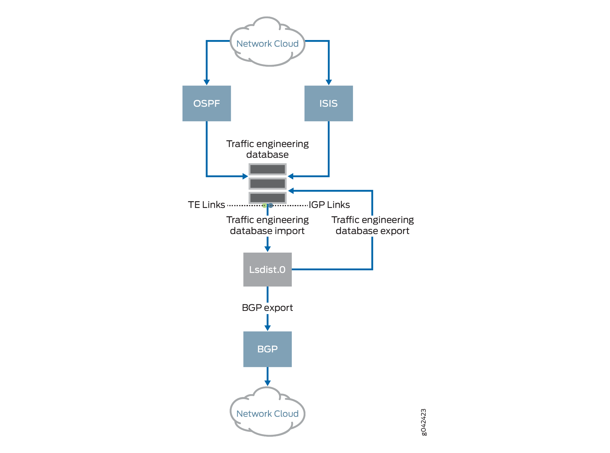
Traffic Engineering Database Import
To advertise the traffic engineering database
into BGP-TE, the link and node entries in the
traffic engineering database are converted in the
form of routes. These converted routes are then
installed by the traffic engineering database on
behalf of the corresponding IGP, into a
user-visible routing table called
lsdist.0, on conditions subject
to route policies. The procedure of leaking
entries from the traffic engineering database into
lsdist.0 is called traffic
engineering database import as illustrated in
Figure 1.
There are polices to govern the traffic
engineering database import process. By default,
no entries are leaked from the traffic engineering
database into the lsdist.0
table.
The
traffic engineering database installs interior gateway protocol (IGP) topology
information in addition to RSVP-TE topology information in the lsdist.0 routing table
as illustrated in Figure 1.
You
can monitor both IGP and traffic engineering topology information. The BGP-LS reads
IGP entries from lsdist.0 and advertises these entries to the BGP peers. To import IGP
topology information into BGP-LS from lsdist.0, use the set bgp-ls
configuration statement at the [edit protocols mpls traffic-engineering
database import igp-topology] hierarchy level.
Traffic Engineering Database Export
BGP can be configured to export or advertise
routes from the lsdist.0 table,
subject to policy. This is common for any kind of
route origination in BGP. In order to advertise
BGP-TE into the traffic engineering database, BGP
needs to be configured with the BGP-TE address
family, and an export policy that selects routes
for redistribution into BGP.
BGP then propagates these routes like any other
NLRI. BGP peers that have the BGP-TE family
configured and negotiated receive BGP-TE NLRIs.
BGP stores the received BGP-TE NLRIs in the form
of routes in the lsdist.0 table,
which is the same table that stores locally
originated BGP-TE routes. The BGP-installed routes
in lsdist.0 are then distributed
to other peers like any other route. Thus, the
standard route selection procedure applies to
BGP-TE NLRIs received from multiple speakers.
To achieve interdomain TE, the routes in
lsdist.0 are leaked into the
traffic engineering database through a policy.
This process is called traffic engineering
database export as illustrated in Figure 1.
There are polices to govern the traffic
engineering database export process. By default,
no entries are leaked from the
lsdist.0 table into the traffic
engineering database.
You can distribute the traffic engineering (TE) policies that originate from the segment routing protocol to the traffic engineering database (TED) and into the BGP link-state as routes. BGP link-state collects the information related to the TE policies, so that the external controllers can perform actions such as path-computation, re-optimization, and network visualization within and across domains.
Configure set protocols
source-packet-routing traffic-engineering
database to allow the segment routing
(SR) policies to be stored in TED.
For SDN applications, such as PCE and ALTO, the BGP-TE advertised information cannot leak into the traffic engineering database of a router. In such cases, an external server that peers with the routers using BGP-TE is used to move topology information up into the sky/orchestration system that spans the network. These external servers can be deemed as BGP-TE consumers, where they receive BGP-TE routes, but do not advertise them.
Assigning Credibility Values
Once the entries are installed in the traffic engineering database, the BGP-TE learned information is made available for CSPF path computation. The traffic engineering database uses a protocol preference scheme that is based on credibility values. A protocol with a higher credibility value is preferred over a protocol with a lower credibility value. BGP-TE has the capability to advertise information learned from multiple protocols at the same time, and so in addition to the IGP-installed entries in the traffic engineering database, there can be BGP-TE installed entries that correspond to more than one protocol. The traffic engineering database export component creates a traffic engineering database protocol and credibility level for each protocol that BGP-TE supports. These credibility values are configurable in the CLI.
The credibility order for the BGP-TE protocols is as follows:
-
Unknown—80
-
OSPF—81
-
IS-IS Level 1—82
-
IS-IS Level 2—83
-
Static—84
-
Direct—85
Cross-Credibility Path Computation
After you assign credibility values, each credibility level is treated as an individual plane. The Constrained Shorted Path First algorithm starts with the highest assigned credibility to the lowest, finding a path within that credibility level.
With BGP-TE, it is essential to compute paths across credibility levels to compute inter-AS paths. For example, different credibility settings are seen on a device from area 0 that computes the path through area 1, because area 0 entries are installed by OSPF, and area 1 entries are installed by BGP-TE.
To enable path computation across credibility
levels, include the
cross-credibility-cspf statement
at the edit protocols mpls,
[edit protocols mpls label-switched-path
                                                  lsp-name]
, and
[edit protocols
                                                  rsvp]
hierarchy
levels. At the [edit protocols
rsvp] hierarchy level, enabling
cross-credibility-cspf impacts
bypass LSPs and loose hop expansion in
transit.
Configuring
cross-credibility-cspf enables
path computation across credibility levels using
the Constrained Shortest Path First algorithm,
wherein the constraint is not performed on a
credibility-by-credibility basis, but as a single
constraint ignoring the assigned credibility
values.
BGP-TE NLRIs and TLVs
Like other BGP routes, BGP-TE NLRIs can also be distributed through a route reflector that speaks BGP-TE NLRI. Junos OS implements the route reflection support for the BGP-TE family.
The following is a list of supported NLRIs:
-
Link NLRI
-
Node NLRI
-
IPv4 Prefix NLRI (receive and propagate)
-
IPv6 Prefix NLRI (receive and propagate)
-
TE policy NLRI
Junos OS does not provide support for the route-distinguisher form of the above NRLIs.
The following is a list of supported fields in link and node NLRIs:
-
Protocol-ID—NLRI originates with the following protocol values:
-
IS-IS-L1
-
IS-IS-L2
-
OSPF
-
SPRING-TE
-
-
Identifier—This value is configurable. By default, the identifier value is set to
0. -
Local/Remote node descriptor—These include:
-
Autonomous system
-
BGP-LS Identifier—This value is configurable. By default, the BGP-LS identifier value is set to
0 -
Area-ID
-
IGP router-ID
-
-
Link descriptors (Only for link NLRI)—This includes:
-
Link Local/Remote Identifiers
-
IPv4 interface address
-
IPv4 neighbor address
-
IPv6 neighbor/interface address—The IPv6 neighbor and interface addresses are not originated, but only stored and propagated when received.
-
Multi-topology ID—This value is not originated, but stored and propagated when received.
-
The following is a list of supported LINK_STATE attribute TLVs:
-
Link attributes:
-
Administrative group
-
Max link bandwidth
-
Max reservable bandwidth
-
Unreserved bandwidth
-
TE default metric
-
SRLG
-
The following TLVs, which are not originated, but only stored and propagated when received:
-
Opaque link attributes
-
MPLS protocol mask
-
Metric
-
Link protection type
-
Link name attribute
-
-
-
Node attributes:
-
IPv4 Router-ID
-
Node flag bits—Only the overload bit is set.
-
The following TLVs, which are not originated, but only stored and propagated when received:
-
Multi-topology
-
OSPF-specific node properties
-
Opaque node properties
-
Node name
-
IS-IS area identifier
-
IPv6 Router-ID
-
-
Prefix attributes—These TLVs are stored and propagated like any other unknown TLVs.
-
Supported and Unsupported Features
Junos OS supports the following features with link-state distribution using BGP:
Advertisement of multiprotocol assured forwarding capability
Transmission and reception of node and link-state BGP and BGP-TE NLRIs
Nonstop active routing for BGP-TE NLRIs
Policies
Junos OS does not support the following functionality for link-state distribution using BGP:
Aggregated topologies, links, or nodes
Route distinguisher support for BGP-TE NLRIs
Multi-topology identifiers
Multi-instance identifiers (excluding the default instance ID 0)
Advertisement of the link and node area TLV
Advertisement of MPLS signaling protocols
Importing node and link information with overlapping address
BGP Link-State Extensions for Source Packet Routing in Networking (SPRING)
The BGP link-state address family is extended to distribute the source packet routing in networking (SPRING) topology information to software-defined networking (SDN) controllers. BGP typically learns the link-state information from IGP and distributes it to BGP peers. Besides BGP, the SDN controller can get link-state information directly from IGP if the controller is a part of an IGP domain. However, BGP link-state distribution provides a scalable mechanism to export the topology information. BGP link-state extensions for SPRING is supported on interdomain networks.
- Source Packet Routing in Networking (SPRING)
- Flow of BGP Link-State SPRING Data
- Supported BGP Link-State Attributes and TLVs, and Unsupported Features for BGP Link-State with SPRING
Source Packet Routing in Networking (SPRING)
SPRING is a control-plane architecture that enables an ingress router to steer a packet through a specific set of nodes and links in the network without relying on the intermediate nodes in the network to decide the actual path it must take. SPRING engages IGPs, such as IS-IS and OSPF, for advertising network segments. Network segments can represent any instruction, topological or service-based. Within IGP topologies, IGP segments are advertised by the link-state routing protocols. There are two types of IGP segments:
| Adjacency segment |
A one-hop path over a specific adjacency between two nodes in the IGP |
| Prefix segment |
A multi-hop, equal-cost, multipath-aware shortest-path to a prefix, as per the state of the IGP topology |
When SPRING in enabled in a BGP network, BGP link-state address family learns the SPRING information from the IGP link-state routing protocols and advertises segments in the form of segment identifiers (SIDs). BGP link-state address family has been extended to carry SIDs and other SPRING-related information to BGP peers. The route reflector can steer a packet through a desired set of nodes and links by prepending the packet with an appropriate combination of tunnels. This feature allows BGP link-state address family to also advertise the SPRING information to BGP peers.
Flow of BGP Link-State SPRING Data
Figure 2 depicts the data flow of BGP link-state SPRING data that IS-IS pushes to the traffic engineering database.
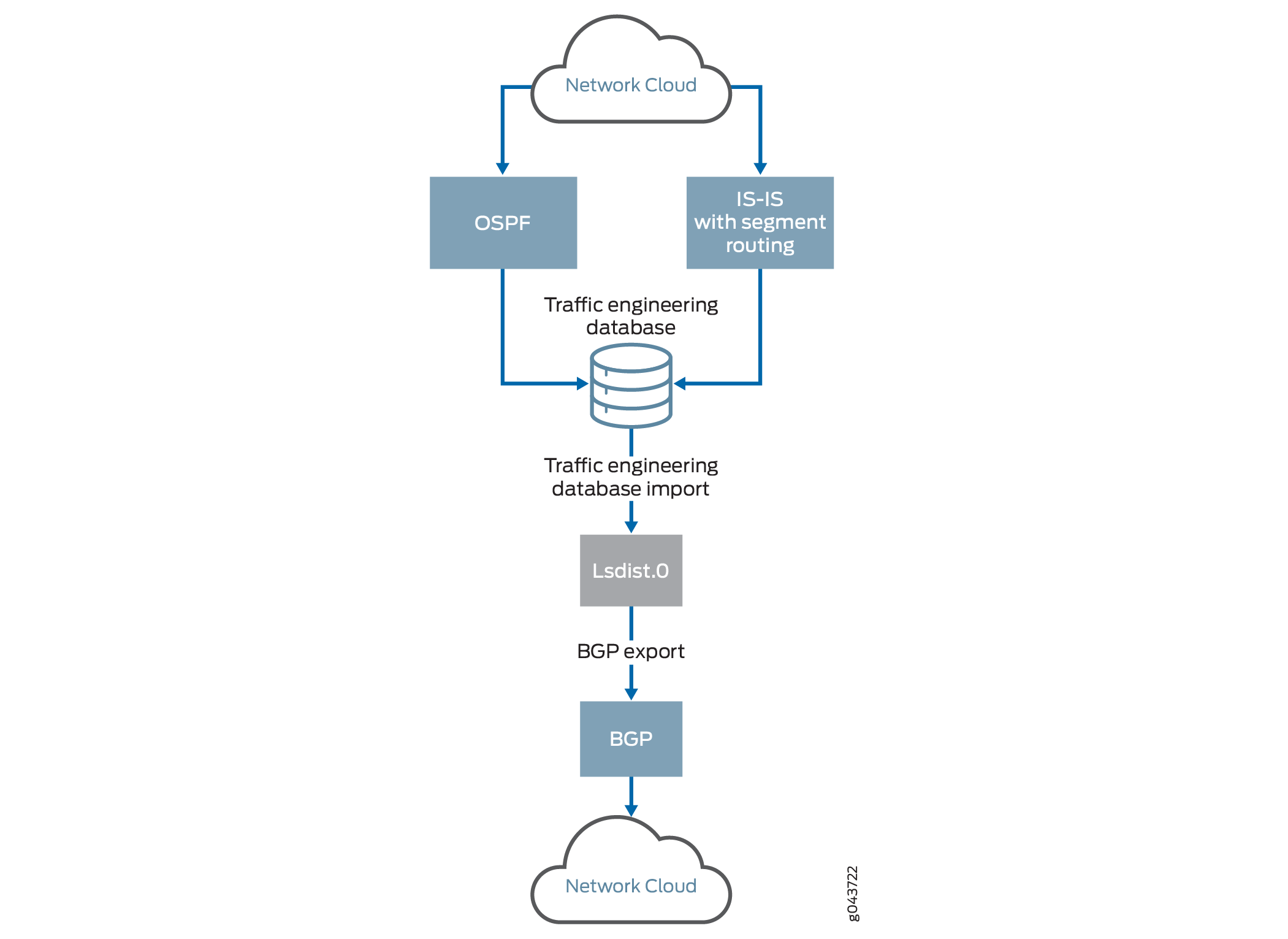
-
IGP pushes the SPRING attributes to the traffic engineering database.
-
SPRING capabilities and algorithm information are carried forward as node attributes into the traffic engineering database.
-
Adjacent SID and LAN adjacent SID information are carried as link attributes.
-
Prefix SID or node-SID information is carried as prefix attributes.
-
A new set or a change to existing attributes triggers IGP updates to the traffic engineering database with new data.
CAUTION:If traffic engineering is disabled at the IGP level, none of the attributes are pushed to the traffic engineering database.
-
All parameters in the BGP traffic engineering NLRI, including the link, node, and prefix descriptors are derived from entries in the traffic engineering database.
-
The traffic engineering database imports route entries into the
lsdist.0routing table from IGP subject to policy. -
The default policy of BGP is to export routes, which are known to BGP only. You configure an export policy for non-BGP routes in the
lsdis.0routing table. This policy advertises an entry learned from the traffic engineering database.
Supported BGP Link-State Attributes and TLVs, and Unsupported Features for BGP Link-State with SPRING
BGP link-state with SPRING supports the following attributes and type, length, and values (TLVs) that are originated, received, and propagated in the network:
Node attributes
-
Segment routing Capabilities
-
Segment routing Algorithm
Link attributes
-
Adjacent-SID
-
LAN Adjacent-SID
Prefix descriptors
-
IP reachability information
Prefix attributes
-
Prefix SID
The following list supports TLVs that are not originated, but only received and propagated in the network:
Prefix descriptors
-
Multitopology ID
-
OSPF route type
Prefix attributes
-
Range
-
Binding SID
Junos OS does not support the following features with BGP link-state with SPRING extensions:
-
IPv6 prefix origination
-
Multitopology identifiers
-
Traffic engineering database export for SPRING parameters
-
New TLVs with tcpdump (existing TLVs are also not supported).
-
SPRING over IPv6
Verifying NLRI Node Learned Through BGP with OSPF as IGP
The following is a sample output to verify the NLRI node learned through BGP with OSPF as the IGP:
Purpose
Verify the lsdist.0 routing table entries.
Action
From operational mode, run the show route
table lsdist.0 command.
user@host> show route table lsdist.0 te-node-ip 10.7.7.7 extensive
lsdist.0: 216 destinations, 216 routes (216 active, 0 holddown, 0 hidden)
NODE { AS:65100 Area:0.0.0.1 IPv4:10.7.7.7 OSPF:0 }/1536 (1 entry, 1 announced)
TSI:
LINK-STATE attribute handle 0x61d5da0
        *BGP    Preference: 170/-101
                Next hop type: Indirect, Next hop index: 0
                Address: 0x61b07cc
                Next-hop reference count: 216
                Source: 10.2.2.2
                Protocol next hop: 10.2.2.2
                Indirect next hop: 0x2 no-forward INH Session ID: 0x0
                State:<Active Int Ext>
                Local AS:   65100 Peer AS:   65100
                Age: 30:22      Metric2: 2
                Validation State: unverified
                Task: BGP_65100.10.2.2.2
                Announcement bits (1): 0-TED Export
                AS path: I
                Accepted
                Area border router: No
                External router: No
                Attached: No
                Overload: No
                SPRING-Capabilities:
                 - SRGB block [Start: 900000, Range: 90000, Flags: 0x00]
                SPRING-Algorithms:
                 - Algo: 0
                Localpref: 100
                Router ID: 10.2.2.2
                Indirect next hops: 1
                        Protocol next hop: 10.2.2.2 Metric: 2
                        Indirect next hop: 0x2 no-forward INH Session ID: 0x0
                        Indirect path forwarding next hops: 1
                                Next hop type: Router
                                Next hop: 10.11.1.2 via et-0/0/0.1 weight 0x1
                                Session Id: 0x143
                                10.2.2.2/32 Originating RIB: inet.0
                                  Metric: 2     Node path count: 1
                                  Forwarding nexthops: 1
                                        Nexthop: 10.11.1.2 via et-0/0/0.1
                                        Session Id: 143
Meaning
The routes are appearing in the lsdist.0 routing table.
Verifying the Prefix NLRI Learned Through BGP with OSPF as IGP
The following is a sample output to verify the prefix NLRI learned through BGP with OSPF as the IGP:
Purpose
Verify the lsdist.0 routing table entries.
Action
From operational mode, run the show route table lsdist.0 command.
user@host> show route table lsdist.0 te-ipv4-prefix-node-ip 10.7.7.7 extensive
lsdist.0: 216 destinations, 216 routes (216 active, 0 holddown, 0 hidden)
PREFIX { Node { AS:65100 Area:0.0.0.1 IPv4:10.7.7.7 } { IPv4:10.7.7.7/32 } OSPF:0 }/1536 (1 entry, 0 announced)
        *BGP    Preference: 170/-101
                Next hop type: Indirect, Next hop index: 0
                Address: 0x61b07cc
                Next-hop reference count: 216
                Source: 10.2.2.2
                Protocol next hop: 10.2.2.2
                Indirect next hop: 0x2 no-forward INH Session ID: 0x0
                State: <Active Int Ext>
                Local AS:   65100 Peer AS:   65100
                Age: 30:51      Metric2: 2
                Validation State: unverified
                Task: BGP_65100.10.2.2.2
                AS path: I
                Accepted
                Prefix Flags: 0x00, Prefix SID: 1007, Flags: 0x50, Algo: 0
                Localpref: 65100
                Router ID: 10.2.2.2
                Indirect next hops: 1
                        Protocol next hop: 10.2.2.2 Metric: 2
                        Indirect next hop: 0x2 no-forward INH Session ID: 0x0
                        Indirect path forwarding next hops: 1
                                Next hop type: Router
                                Next hop: 10.11.1.2 via et-0/0/0.1 weight 0x1
                                Session Id: 0x143
                                10.2.2.2/32 Originating RIB: inet.0
                                  Metric: 2     Node path count: 1
                                  Forwarding nexthops: 1
                                        Nexthop: 10.11.1.2 via et-0/0/0.1
                                        Session Id: 143
Meaning
The routes are appearing in the lsdist.0 routing table.
Example: Configuring Link State Distribution Using BGP
This example shows how to configure BGP to carry link-state information across multiple domains, which is used for computing paths for MPLS LSPs spanning multiple domains, such as inter-area TE LSP, and providing a scalable and policy-controlled means for external path computing entities, such as ALTO and PCE, to acquire network topology.
Requirements
This example uses the following hardware and software components:
-
Four MX Series routers
-
Junos OS Release 14.2 or later running on all the routers
Before you begin:
-
Configure the device interfaces.
-
Configure the autonomous system numbers and router IDs for the devices.
-
Configure the following protocols:
-
RSVP
-
MPLS
-
BGP
-
IS-IS
-
OSPF
-
Overview
A new mechanism to distribute topology information across multiple areas and autonomous systems (ASs) is introduced by extending the BGP protocol to carry link -state information, which was initially acquired using IGP. The IGP protocols have scaling limitations when it comes to distributing large databases. BGP is not only a more scalable vehicle for carrying multi-area and multi-AS topology information, but also provides the policy controls that can be useful for multi-AS topology distribution. The BGP link-state topology information is used for computing paths for MPLS label-switched paths (LSPs) spanning multiple domains, such as inter-area TE LSP, and providing a scalable and policy-controlled means for external path computing entities, such as ALTO and PCE, to acquire network topology.
Link state distribution using BGP is supported on QFX10000 switches.
Topology
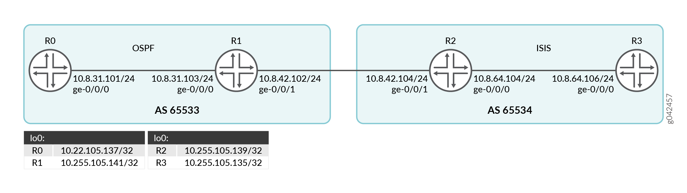
In Figure 3, Routers R0 and R1 and Routers R2 and R3 belong to different autonomous systems. Routers R0 and R1 run OSPF, and Routers R2 and R3 run IS-IS.
Configuration
CLI Quick Configuration
To quickly configure this example, copy the following commands, paste them into a
text file, remove any line breaks, change any details necessary to match your
network configuration, copy and paste the commands into the CLI at the
[edit] hierarchy level, and then enter
commit from configuration mode.
R0
set interfaces ge-0/0/0 unit 0 family inet address 10.8.31.101/24
set interfaces ge-0/0/0 unit 0 family iso
set interfaces ge-0/0/0 unit 0 family mpls
set interfaces lo0 unit 0 family inet address 10.255.105.137/32
set routing-options router-id 10.255.105.137
set routing-options autonomous-system 65533
set protocols rsvp interface all
set protocols rsvp interface fxp0.0 disable
set protocols mpls traffic-engineering database export policy accept-all
set protocols mpls cross-credibility-cspf
set protocols mpls label-switched-path to-R3-inter-as to 10.255.105.135
set protocols mpls label-switched-path to-R3-inter-as bandwidth 40m
set protocols mpls interface all
set protocols mpls interface fxp0.0 disable
set protocols bgp group ibgp type internal
set protocols bgp group ibgp local-address 10.255.105.137
set protocols bgp group ibgp family traffic-engineering unicast
set protocols bgp group ibgp neighbor 10.255.105.141
set protocols ospf traffic-engineering
set protocols ospf area 0.0.0.0 interface lo0.0
set protocols ospf area 0.0.0.0 interface ge-0/0/0.0
set policy-options policy-statement accept-all from family traffic-engineering
set policy-options policy-statement accept-all then accept
R1
set interfaces ge-0/0/0 unit 0 family inet address 10.8.31.103/24
set interfaces ge-0/0/0 unit 0 family iso
set interfaces ge-0/0/0 unit 0 family mpls
set interfaces ge-0/0/1 unit 0 family inet address 10.8.42.102/24
set interfaces ge-0/0/1 unit 0 family iso
set interfaces ge-0/0/1 unit 0 family mpls
set interfaces lo0 unit 0 family inet address 10.255.105.141/32
set interfaces lo0 unit 0 family iso address 47.0005.0102.5501.8181
set routing-options router-id 10.255.105.141
set routing-options autonomous-system 65533
set protocols rsvp interface all
set protocols rsvp interface fxp0.0 disable
set protocols mpls interface all
set protocols mpls interface fxp0.0 disable
set protocols bgp group ibgp type internal
set protocols bgp group ibgp local-address 10.255.105.141
set protocols bgp group ibgp family traffic-engineering unicast
set protocols bgp group ibgp export nlri2bgp
set protocols bgp group ibgp neighbor 10.255.105.137
set protocols bgp group ebgp type external
set protocols bgp group ebgp family traffic-engineering unicast
set protocols bgp group ebgp neighbor 10.8.42.104 local-address 10.8.42.102
set protocols bgp group ebgp neighbor 10.8.42.104 peer-as 65534
set protocols isis interface ge-0/0/1.0 passive remote-node-iso 0102.5502.4211
set protocols isis interface ge-0/0/1.0 passive remote-node-id 10.8.42.104
set protocols ospf traffic-engineering
set protocols ospf area 0.0.0.0 interface lo0.0
set protocols ospf area 0.0.0.0 interface ge-0/0/0.0
set protocols ospf area 0.0.0.0 interface ge-0/0/1.0 passive traffic-engineering remote-node-id 10.8.42.104
set protocols ospf area 0.0.0.0 interface ge-0/0/1.0 passive traffic-engineering remote-node-router-id 10.255.105.139
set policy-options policy-statement accept-all from family traffic-engineering
set policy-options policy-statement accept-all then accept
set policy-options policy-statement nlri2bgp term 1 from family traffic-engineering
set policy-options policy-statement nlri2bgp term 1 then accept
R2
set interfaces ge-0/0/0 unit 0 family inet address 10.8.64.104/24
set interfaces ge-0/0/0 unit 0 family iso
set interfaces ge-0/0/0 unit 0 family mpls
set interfaces ge-0/0/1 unit 0 family inet address 10.8.42.104/24
set interfaces ge-0/0/1 unit 0 family iso
set interfaces ge-0/0/1 unit 0 family mpls
set interfaces lo0 unit 0 family inet address 10.255.105.139/32
set interfaces lo0 unit 0 family iso address 47.0005.0102.5502.4211.00
set routing-options router-id 10.255.105.139
set routing-options autonomous-system 65534
set protocols rsvp interface all
set protocols rsvp interface fxp0.0 disable
set protocols mpls traffic-engineering database import policy ted2nlri
set protocols mpls interface all
set protocols mpls interface fxp0.0 disable
set protocols bgp group ibgp type internal
set protocols bgp group ibgp local-address 10.255.105.139
set protocols bgp group ibgp family traffic-engineering unicast
set protocols bgp group ibgp export nlri2bgp
set protocols bgp group ibgp neighbor 10.255.105.135
set protocols bgp group ebgp type external
set protocols bgp group ebgp family traffic-engineering unicast
set protocols bgp group ebgp export nlri2bgp
set protocols bgp group ebgp peer-as 65533
set protocols bgp group ebgp neighbor 10.8.42.102
set protocols isis level 1 disable
set protocols isis interface ge-0/0/0.0
set protocols isis interface ge-0/0/1.0 passive remote-node-iso 0102.5501.8181
set protocols isis interface ge-0/0/1.0 passive remote-node-id 10.8.42.102
set protocols isis interface lo0.0
set protocols ospf traffic-engineering
set protocols ospf area 0.0.0.0 interface ge-0/0/1.0 passive traffic-engineering remote-node-id 10.8.42.102
set protocols ospf area 0.0.0.0 interface ge-0/0/1.0 passive traffic-engineering remote-node-router-id 10.255.105.141
set policy-options policy-statement accept-all from family traffic-engineering
set policy-options policy-statement accept-all then accept
set policy-options policy-statement nlri2bgp term 1 from family traffic-engineering
set policy-options policy-statement nlri2bgp term 1 then accept
set policy-options policy-statement ted2nlri term 1 from protocol isis
set policy-options policy-statement ted2nlri term 1 from protocol ospf
set policy-options policy-statement ted2nlri term 1 then accept
set policy-options policy-statement ted2nlri term 2 then reject
R3
set interfaces ge-0/0/0 unit 0 family inet address 10.8.64.106/24
set interfaces ge-0/0/0 unit 0 family iso
set interfaces ge-0/0/0 unit 0 family mpls
set interfaces lo0 unit 0 family inet address 10.255.105.135/32
set interfaces lo0 unit 0 family iso address 47.0005.0102.5502.4250
set routing-options router-id 10.255.105.135
set routing-options autonomous-system 65534
set protocols rsvp interface all
set protocols rsvp interface fxp0.0 disable
set protocols mpls traffic-engineering database export policy accept-all
set protocols mpls interface all
set protocols mpls interface fxp0.0 disable
set protocols bgp group ibgp type internal
set protocols bgp group ibgp local-address 10.255.105.135
set protocols bgp group ibgp family traffic-engineering unicast
set protocols bgp group ibgp neighbor 10.255.105.139
set protocols isis interface ge-0/0/0.0 level 1 disable
set protocols isis interface lo0.0
set protocols ospf traffic-engineering
set protocols ospf area 0.0.0.0 interface lo0.0
set protocols ospf area 0.0.0.0 interface ge-0/0/0.0
set policy-options policy-statement accept-all from family traffic-engineering
set policy-options policy-statement accept-all then accept
Procedure
Step-by-Step Procedure
The following example requires you to navigate various levels in the configuration hierarchy. For information about navigating the CLI, see Using the CLI Editor in Configuration Mode.
To configure Router R1:
-
Configure the Router R1 interfaces.
[edit interfaces]
user@R1# set ge-0/0/0 unit 0 family inet address 10.8.31.103/24
user@R1# set ge-0/0/0 unit 0 family iso
user@R1# set ge-0/0/0 unit 0 family mpls
user@R1# set ge-0/0/1 unit 0 family inet address 10.8.42.102/24
user@R1# set ge-0/0/1 unit 0 family iso
user@R1# set ge-0/0/1 unit 0 family mpls
user@R1# set lo0 unit 0 family inet address 10.255.105.141/32
user@R1# set lo0 unit 0 family iso address 47.0005.0102.5501.8181
-
Configure the router ID and autonomous system of Router R1.
[edit routing-options]user@R1# set router-id 10.255.105.141 user@R1# set autonomous-system 65533 -
Enable RSVP on all the interfaces of Router R1 (excluding the management interface).
[edit protocols]user@R1# set rsvp interface all user@R1# set rsvp interface fxp0.0 disable -
Enable MPLS on all the interfaces of Router R1 (excluding the management interface).
[edit protocols]user@R1# set mpls interface all user@R1# set mpls interface fxp0.0 disable -
Configure the BGP group for Router R1 to peer with Router R0, and assign the local address and neighbor address.
[edit protocols]user@R1# set bgp group ibgp type internal user@R1# set bgp group ibgp local-address 10.255.105.141 user@R1# set bgp group ibgp neighbor 10.255.105.137 -
Include the BGP-TE signaling network layer reachability information (NLRI) to the ibgp BGP group.
[edit protocols]user@R1# set bgp group ibgp family traffic-engineering unicast -
Enable export of policy nlri2bgp on Router R1.
[edit protocols]user@R1# set bgp group ibgp export nlri2bgp -
Configure the BGP group for Router R1 to peer with Router R2, and assign the local address and neighbor autonomous system to the ebgp BGP group.
[edit protocols]user@R1# set bgp group ebgp type external user@R1# set bgp group ebgp neighbor 10.8.42.104 local-address 10.8.42.102 user@R1# set bgp group ebgp neighbor 10.8.42.104 peer-as 65534 -
Include the BGP-TE signaling NLRI to the ebgp BGP group.
[edit protocols]user@R1# set bgp group ebgp family traffic-engineering unicast -
Enable passive traffic-engineering on the inter-AS link.
[edit protocols]user@R1# set isis interface ge-0/0/1.0 passive remote-node-iso 0102.5502.4211 user@R1# set isis interface ge-0/0/1.0 passive remote-node-id 10.8.42.104 -
Enable OSPF on the interface connecting Router R1 to Router R0 and on the loopback interface of Router R1, and enable traffic engineering capabilities.
[edit protocols]user@R1# set ospf traffic-engineering user@R1# set ospf area 0.0.0.0 interface lo0.0 user@R1# set ospf area 0.0.0.0 interface ge-0/0/0.0 -
Enable passive traffic-engineering on the inter-AS link.
[edit protocols]user@R1# set ospf area 0.0.0.0 interface ge-0/0/1.0 passive traffic-engineering remote-node-id 10.8.42.104 user@R1# set ospf area 0.0.0.0 interface ge-0/0/1.0 passive traffic-engineering remote-node-router-id 10.255.105.139 -
Configure policies to accept traffic from BGP-TE NLRI.
[edit policy-options]user@R1# set policy-statement accept-all from family traffic-engineering user@R1# set policy-statement accept-all then accept user@R1# set policy-statement nlri2bgp term 1 from family traffic-engineering user@R1# set policy-statement nlri2bgp term 1 then accept
Results
From configuration mode, confirm your configuration by entering the
show interfaces, show routing-options,
show protocols, and show
policy-options commands. If the output does not display the
intended configuration, repeat the instructions in this example to correct
the configuration.
user@R1# show interfaces
ge-0/0/0 {
    unit 0 {
        family inet {
            address 10.8.31.103/24;
        }
        family iso;
        family mpls;
    }
}
ge-0/0/1 {
    unit 0 {
        family inet {
            address 10.8.42.102/24;
        }
        family iso;
        family mpls;
    }
}
lo0 {
    unit 0 {
        family inet {
            address 10.255.105.141/32;
        family iso {
            address 47.0005.0102.5501.8181:00;
        }
    }
}
user@R1# show routing-options
router-id 10.255.105.141;
autonomous-system 65533;
user@R1# show protocols
rsvp {
    interface all;
    interface fxp0.0 {
        disable;
    }
}
mpls {
    interface all;
    interface fxp0.0 {
        disable;
    }
}
bgp {
    group ibgp {
        type internal;
        local-address 10.255.105.141;
        family traffic-engineering {
            unicast;
        }
        export nlri2bgp;
        neighbor 10.255.105.137;
    }
    group ebgp {
        type external;
        family traffic-engineering {
            unicast;
        }
        neighbor 10.8.42.104 {
            local-address 10.8.42.102;
            peer-as 65534;
        }
    }
}
isis {
    interface ge-0/0/1.0 {
        passive {
            remote-node-iso 0102.5502.4211;
            remote-node-id 10.8.42.104;
        }
    }
}
ospf {
    traffic-engineering;
    area 0.0.0.0 {
        interface lo0.0;
        interface ge-0/0/0.0;
        interface ge-0/0/1.0 {
            passive {
                traffic-engineering {
                    remote-node-id 10.8.42.104;
                    remote-node-router-id 10.255.105.139;
                }
            }
        }
    }
}
user@R1# show policy-options
policy-statement accept-all {
    from family traffic-engineering;
    then accept;
}
policy-statement nlri2bgp {
    term 1 {
        from family traffic-engineering;
        then {
            accept;
        }
    }
}
Procedure
Step-by-Step Procedure
The following example requires you to navigate various levels in the configuration hierarchy. For information about navigating the CLI, see Using the CLI Editor in Configuration Mode.
To configure Router R2:
-
Configure the Router R2 interfaces.
[edit interfaces]
user@R2# set ge-0/0/0 unit 0 family inet address 10.8.64.104/24
user@R2# set ge-0/0/0 unit 0 family iso
user@R2# set ge-0/0/0 unit 0 family mpls
user@R2# set ge-0/0/1 unit 0 family inet address 10.8.42.104/24
user@R2# set ge-0/0/1 unit 0 family iso
user@R2# set ge-0/0/1 unit 0 family mpls
user@R2# set lo0 unit 0 family inet address 10.255.105.139/32
user@R2# set lo0 unit 0 family iso address 47.0005.0102.5502.4211.00
-
Configure the router ID and autonomous system of Router R2.
[edit routing-options]user@R2# set router-id 10.255.105.139 user@R2# set autonomous-system 65534 -
Enable RSVP on all the interfaces of Router R2 (excluding the management interface).
[edit routing-options]user@R2# set rsvp interface all user@R2# set rsvp interface fxp0.0 disable -
Enable MPLS on all the interfaces of Router R2 (excluding the management interface).
[edit routing-options]user@R2# set mpls interface all user@R2# set mpls interface fxp0.0 disable -
Enable import of traffic engineering database parameters using the ted2nlri policy.
[edit protocols]user@R2# set mpls traffic-engineering database import policy ted2nlri -
Configure the BGP group for Router R2 to peer with Router R3, and assign the local address and neighbor address.
[edit protocols]user@R2# set bgp group ibgp type internal user@R2# set bgp group ibgp local-address 10.255.105.139 user@R2# set bgp group ibgp neighbor 10.255.105.135 -
Include the BGP-TE signaling network layer reachability information (NLRI) to the ibgp BGP group.
[edit protocols]user@R2# set bgp group ibgp family traffic-engineering unicast -
Enable export of policy nlri2bgp on Router R2.
[edit protocols]user@R2# set bgp group ibgp export nlri2bgp -
Configure the BGP group for Router R2 to peer with Router R1.
[edit protocols]user@R2# set bgp group ebgp type external -
Include the BGP-TE signaling NLRI to the ebgp BGP group.
[edit protocols]user@R2# set bgp group ebgp family traffic-engineering unicast -
Assign the local address and neighbor autonomous system to the ebgp BGP group.
[edit protocols]user@R2# set bgp group ebgp peer-as 65533 user@R2# set bgp group ebgp neighbor 10.8.42.102 -
Enable export of policy nlri2bgp on Router R2.
[edit protocols]user@R2# set bgp group ebgp export nlri2bgp -
Enable IS-IS on the interface connecting Router R2 with Router R3 and the loopback interface of Router R2.
[edit protocols]user@R2# set isis level 1 disable user@R2# set isis interface ge-0/0/0.0 user@R2# set isis interface lo0.0 -
Enable only IS-IS advertising on the interface connecting Router R2 with Router R1.
[edit protocols]user@R2# set isis interface ge-0/0/1.0 passive remote-node-iso 0102.5501.8181 user@R2# set isis interface ge-0/0/1.0 passive remote-node-id 10.8.42.102 -
Configure traffic engineering capability on Router R2.
[edit protocols]user@R2# set ospf traffic-engineering -
Enable only OSPF advertisements on the interface connecting Router R2 with Router R1.
[edit protocols]user@R2# set ospf area 0.0.0.0 interface ge-0/0/1.0 passive traffic-engineering remote-node-id 10.8.42.102 user@R2# set ospf area 0.0.0.0 interface ge-0/0/1.0 passive traffic-engineering remote-node-router-id 10.255.105.141 -
Configure policies to accept traffic from the BGP-TE NLRI.
[edit policy-options]user@R2# set policy-statement accept-all from family traffic-engineering user@R2# set policy-statement accept-all then accept user@R2# set policy-statement nlri2bgp term 1 from family traffic-engineering user@R2# set policy-statement nlri2bgp term 1 then accept user@R2# set policy-statement ted2nlri term 1 from protocol isis user@R2# set policy-statement ted2nlri term 1 from protocol ospf user@R2# set policy-statement ted2nlri term 1 then accept user@R2# set policy-statement ted2nlri term 2 then reject
Results
From configuration mode, confirm your configuration by entering the
show interfaces, show routing-options,
show protocols, and show
policy-options commands. If the output does not display the
intended configuration, repeat the instructions in this example to correct
the configuration.
user@R2# show interfaces
ge-0/0/0 {
    unit 0 {
        family inet {
            address 10.8.64.104/24;
        }
        family iso;
        family mpls;
    }
}
ge-0/0/1 {
    unit 0 {
        family inet {
            address 10.8.42.104/24;
        }
        family iso;
        family mpls;
    }
}
lo0 {
    unit 0 {
        family inet {
            address 10.255.105.139/32;
        family iso {
            address 47.0005.0102.5502.4211.00;
        }
        family iso;
    }
}
user@R2# show routing-options
router-id 10.255.105.139;
 autonomous-system 65534;
user@R2# show protocols
rsvp {
    interface all;
    interface fxp0.0 {
        disable;
    }
}
mpls {
    traffic-engineering {
        database {
            import {
                policy ted2nlri;
            }
        }
    }
    interface all;
    interface fxp0.0 {
        disable;
    }
}
bgp {

    group ibgp {
        type internal;
        local-address 10.255.105.139;
        family traffic-engineering {
            unicast;
        }
        export nlri2bgp;
        neighbor 10.255.105.135;
    }
    group ebgp {
        type external;
        family traffic-engineering {
            unicast;
        }
        export nlri2bgp;
        peer-as 65533;
        neighbor 10.8.42.102;
    }
}
isis {
    level 1 disable;
    interface ge-0/0/0.0;
    interface ge-0/0/1.0 {
        passive {
            remote-node-iso 0102.5501.8181;
            remote-node-id 10.8.42.102;
        }
    }
    interface lo0.0;
}
ospf {
    traffic-engineering;
    area 0.0.0.0 {
        interface ge-0/0/1.0 {
            passive {
                traffic-engineering {
                    remote-node-id 10.8.42.102;
                    remote-node-router-id 10.255.105.141;
                }
            }
        }
    }
}
user@R2# show policy-options
policy-statement accept-all {
    from family traffic-engineering;
    then accept;
}
policy-statement nlri2bgp {
    term 1 {
        from family traffic-engineering;
        then {
            accept;
        }
    }
}
policy-statement ted2nlri {
    term 1 {
        from protocol [ isis ospf ];
        then accept;
    }
    term 2 {
        then reject;
    }
}
Verification
Verify that the configuration is working properly.
- Verifying the BGP Summary Status
- Verifying the MPLS LSP Status
- Verifying the lsdist.0 Routing Table Entries
- Verifying the Traffic Engineering Database Entries
Verifying the BGP Summary Status
Purpose
Verify that BGP is up and running on Routers R0 and R1.
Action
From operational mode, run the show bgp summary command.
user@R0> show bgp summary
Groups: 1 Peers: 1 Down peers: 0
Table          Tot Paths  Act Paths Suppressed    History Damp State    Pending
lsdist.0
                      10         10          0          0          0          0
Peer                     AS      InPkt     OutPkt    OutQ   Flaps Last Up/Dwn State|#Active/Received/Accepted/Damped...
10.255.105.141        65533         20         14       0      79        5:18 Establ
  lsdist.0: 10/10/10/0
From operational mode, run the show bgp summary command.
user@R1> show bgp summary
Groups: 2 Peers: 2 Down peers: 0
Table          Tot Paths  Act Paths Suppressed    History Damp State    Pending
lsdist.0
                      10         10          0          0          0          0
Peer                     AS      InPkt     OutPkt    OutQ   Flaps Last Up/Dwn State|#Active/Received/Accepted/Damped...
10.8.42.104           65534         24         17       0      70        6:43 Establ
  lsdist.0: 10/10/10/0
10.255.105.137        65533         15         23       0      79        6:19 Establ
  lsdist.0: 0/0/0/0
Meaning
Router R0 is peered with Router R1.
Verifying the MPLS LSP Status
Purpose
Verify the status of the MPLS LSP on Router R0.
Action
From operational mode, run the show mpls lsp command.
user@R0> show mpls lsp
Ingress LSP: 1 sessions
To              From            State Rt P     ActivePath       LSPname
10.255.105.135  10.255.105.137  Up     0 *                      to-R3-inter-as
Total 1 displayed, Up 1, Down 0

Egress LSP: 0 sessions
Total 0 displayed, Up 0, Down 0

Transit LSP: 0 sessions
Total 0 displayed, Up 0, Down 0
Meaning
The MPLS LSP from Router R0 to Router R3 is established.
Verifying the lsdist.0 Routing Table Entries
Purpose
Verify the lsdist.0 routing table entries on Routers R0, R1, and R2.
Action
From operational mode, run the show route table lsdist.0
command.
user@R0> show route table lsdist.0
lsdist.0: 10 destinations, 10 routes (10 active, 0 holddown, 0 hidden)
+ = Active Route, - = Last Active, * = Both

NODE { AS:65534 ISO:0102.5502.4211.00 ISIS-L2:0 }/1152
                   *[BGP/170] 00:17:32, localpref 100, from 10.255.105.141
                      AS path: 65534 I, validation-state: unverified
                    > to 10.8.31.103 via ge-0/0/0.0
NODE { AS:65534 ISO:0102.5502.4250.00 ISIS-L2:0 }/1152
                   *[BGP/170] 00:17:32, localpref 100, from 10.255.105.141
                      AS path: 65534 I, validation-state: unverified
                    > to 10.8.31.103 via ge-0/0/0.0
NODE { AS:65534 ISO:0102.5502.4250.02 ISIS-L2:0 }/1152
                   *[BGP/170] 00:17:32, localpref 100, from 10.255.105.141
                      AS path: 65534 I, validation-state: unverified
                    > to 10.8.31.103 via ge-0/0/0.0
NODE { AS:65534 Area:0.0.0.0 IPv4:10.255.105.139 OSPF:0 }/1152
                   *[BGP/170] 00:17:32, localpref 100, from 10.255.105.141
                      AS path: 65534 I, validation-state: unverified
                    > to 10.8.31.103 via ge-0/0/0.0
LINK { Local { AS:65534 ISO:0102.5502.4211.00 }.{ IPv4:8.42.1.104 } Remote { AS:65534 ISO:0102.5501.8181.00 }.{ IPv4:10.8.42.102 } ISIS-L2:0 }/1152
                   *[BGP/170] 00:17:32, localpref 100, from 10.255.105.141
                      AS path: 65534 I, validation-state: unverified
                    > to 10.8.31.103 via ge-0/0/0.0
LINK { Local { AS:65534 ISO:0102.5502.4211.00 }.{ IPv4:10.8.64.104 } Remote { AS:65534 ISO:0102.5502.4250.02 }.{ } ISIS-L2:0 }/1152
                   *[BGP/170] 00:02:03, localpref 100, from 10.255.105.141
                      AS path: 65534 I, validation-state: unverified
                    > to 10.8.31.103 via ge-0/0/0.0
LINK { Local { AS:65534 ISO:0102.5502.4250.00 }.{ IPv4:10.8.64.106 } Remote { AS:65534 ISO:0102.5502.4250.02 }.{ } ISIS-L2:0 }/1152
                   *[BGP/170] 00:17:32, localpref 100, from 10.255.105.141
                      AS path: 65534 I, validation-state: unverified
                    > to 10.8.31.103 via ge-0/0/0.0
LINK { Local { AS:65534 ISO:0102.5502.4250.02 }.{ } Remote { AS:65534 ISO:0102.5502.4211.00 }.{ } ISIS-L2:0 }/1152
                   *[BGP/170] 00:17:32, localpref 100, from 10.255.105.141
                      AS path: 65534 I, validation-state: unverified
                    > to 10.8.31.103 via ge-0/0/0.0
LINK { Local { AS:65534 ISO:0102.5502.4250.02 }.{ } Remote { AS:65534 ISO:0102.5502.4250.00 }.{ } ISIS-L2:0 }/1152
                   *[BGP/170] 00:17:32, localpref 100, from 10.255.105.141
                      AS path: 65534 I, validation-state: unverified
                    > to 10.8.31.103 via ge-0/0/0.0
LINK { Local { AS:65534 Area:0.0.0.0 IPv4:10.255.105.139 }.{ IPv4:10. 8.42.104 } Remote { AS:65534 Area:0.0.0.0 IPv4:10.255.105.141 }.{ IPv4:10.8.42.102 } OSPF:0 }/1152
                   *[BGP/170] 00:17:32, localpref 100, from 10.255.105.141
                      AS path: 65534 I, validation-state: unverified
                    > to 10.8.31.103 via ge-0/0/0.0
From operational mode, run the show route table lsdist.0
command.
user@R1> show route table lsdist.0
lsdist.0: 10 destinations, 10 routes (10 active, 0 holddown, 0 hidden)
+ = Active Route, - = Last Active, * = Both

NODE { AS:65534 ISO:0102.5502.4211.00 ISIS-L2:0 }/1152
                   *[BGP/170] 00:18:00, localpref 100
                      AS path: 65534 I, validation-state: unverified
                    > to 10.8.42.104 via ge-0/0/1.0
NODE { AS:65534 ISO:0102.5502.4250.00 ISIS-L2:0 }/1152
                   *[BGP/170] 00:18:00, localpref 100
                      AS path: 65534 I, validation-state: unverified
                    > to 10.8.42.104 via ge-0/0/1.0
NODE { AS:65534 ISO:0102.5502.4250.02 ISIS-L2:0 }/1152
                   *[BGP/170] 00:18:00, localpref 100
                      AS path: 65534 I, validation-state: unverified
                    > to 10.8.42.104 via ge-0/0/1.0
NODE { AS:65534 Area:0.0.0.0 IPv4:10.255.105.139 OSPF:0 }/1152
                   *[BGP/170] 00:18:00, localpref 100
                      AS path: 65534 I, validation-state: unverified
                    > to 10.8.42.104 via ge-0/0/1.0
LINK { Local { AS:65534 ISO:0102.5502.4211.00 }.{ IPv4:10.8.42.104 } Remote { AS:65534 ISO:0102.5501.8181.00 }.{ IPv4:10.8.42.102 } ISIS-L2:0 }/1152
                   *[BGP/170] 00:18:00, localpref 100
                      AS path: 65534 I, validation-state: unverified
                    > to 10.8.42.104 via ge-0/0/1.0
LINK { Local { AS:65534 ISO:0102.5502.4211.00 }.{ IPv4:10.8.64.104 } Remote { AS:65534 ISO:0102.5502.4250.02 }.{ } ISIS-L2:0 }/1152
                   *[BGP/170] 00:02:19, localpref 100
                      AS path: 65534 I, validation-state: unverified
                    > to 10.8.42.104 via ge-0/0/1.0
LINK { Local { AS:65534 ISO:0102.5502.4250.00 }.{ IPv4:10.8.64.106 } Remote { AS:65534 ISO:0102.5502.4250.02 }.{ } ISIS-L2:0 }/1152
                   *[BGP/170] 00:18:00, localpref 100
                      AS path: 65534 I, validation-state: unverified
                    > to 10.8.42.104 via ge-0/0/1.0
LINK { Local { AS:65534 ISO:0102.5502.4250.02 }.{ } Remote { AS:65534 ISO:0102.5502.4211.00 }.{ } ISIS-L2:0 }/1152
                   *[BGP/170] 00:18:00, localpref 100
                      AS path: 65534 I, validation-state: unverified
                    > to 10.8.42.104 via ge-0/0/1.0
LINK { Local { AS:65534 ISO:0102.5502.4250.02 }.{ } Remote { AS:65534 ISO:0102.5502.4250.00 }.{ } ISIS-L2:0 }/1152
                   *[BGP/170] 00:18:00, localpref 100
                      AS path: 65534 I, validation-state: unverified
                    > to 10.8.42.104 via ge-0/0/1.0
LINK { Local { AS:65534 Area:0.0.0.0 IPv4:10.255.105.139 }.{ IPv4:10.8.42.104 } Remote { AS:65534 Area:0.0.0.0 IPv4:10.255.105.141 }.{ IPv4:10.8.42.102 } OSPF:0 }/1152
                   *[BGP/170] 00:18:00, localpref 100
                      AS path: 65534 I, validation-state: unverified
                    > to 10.8.42.104 via ge-0/0/1.0
From operational mode, run the show route table lsdist.0
command.
user@R2> show route table lsdist.0
lsdist.0: 10 destinations, 10 routes (10 active, 0 holddown, 0 hidden)
+ = Active Route, - = Last Active, * = Both

NODE { AS:65534 ISO:0102.5502.4211.00 ISIS-L2:0 }/1152
                   *[IS-IS/18] 1d 00:24:39
                      Fictitious
NODE { AS:65534 ISO:0102.5502.4250.00 ISIS-L2:0 }/1152
                   *[IS-IS/18] 00:20:45
                      Fictitious
NODE { AS:65534 ISO:0102.5502.4250.02 ISIS-L2:0 }/1152
                   *[IS-IS/18] 00:20:45
                      Fictitious
NODE { AS:65534 Area:0.0.0.0 IPv4:10.255.105.139 OSPF:0 }/1152
                   *[OSPF/10] 1d 00:24:39
                      Fictitious
LINK { Local { AS:65534 ISO:0102.5502.4211.00 }.{ IPv4:10.8.42.104 } Remote { AS:65534 ISO:0102.5501.8181.00 }.{ IPv4:10.8.42.102 } ISIS-L2:0 }/1152
                   *[IS-IS/18] 00:20:58
                      Fictitious
LINK { Local { AS:65534 ISO:0102.5502.4211.00 }.{ IPv4:10.8.64.104 } Remote { AS:65534 ISO:0102.5502.4250.02 }.{ } ISIS-L2:0 }/1152
                   *[IS-IS/18] 00:02:34
                      Fictitious
LINK { Local { AS:65534 ISO:0102.5502.4250.00 }.{ IPv4:10.8.64.106 } Remote { AS:65534 ISO:0102.5502.4250.02 }.{ } ISIS-L2:0 }/1152
                   *[IS-IS/18] 00:20:45
                      Fictitious
LINK { Local { AS:65534 ISO:0102.5502.4250.02 }.{ } Remote { AS:65534 ISO:0102.5502.4211.00 }.{ } ISIS-L2:0 }/1152
                   *[IS-IS/18] 00:20:45
                      Fictitious
LINK { Local { AS:65534 ISO:0102.5502.4250.02 }.{ } Remote { AS:65534 ISO:0102.5502.4250.00 }.{ } ISIS-L2:0 }/1152
                   *[IS-IS/18] 00:20:45
                      Fictitious
LINK { Local { AS:65534 Area:0.0.0.0 IPv4:10.255.105.139 }.{ IPv4:10.8.42.104 } Remote { AS:65534 Area:0.0.0.0 IPv4:10.255.105.141 }.{ IPv4:10.8.42.102 } OSPF:0 }/1152
                   *[OSPF/10] 00:20:57
                      Fictitious
Meaning
The routes are appearing in the lsdist.0 routing table.
Verifying the Traffic Engineering Database Entries
Purpose
Verify the traffic engineering database entries on Router R0.
Action
From operational mode, run the show ted database
command.
user@R0> show ted database
TED database: 5 ISIS nodes 5 INET nodes
ID                            Type Age(s) LnkIn LnkOut Protocol
0102.5501.8168.00(10.255.105.137) Rtr   1046     1      1 OSPF(0.0.0.0)
    To: 10.8.31.101-1, Local: 10.8.31.101, Remote: 0.0.0.0
      Local interface index: 0, Remote interface index: 0
ID                            Type Age(s) LnkIn LnkOut Protocol
0102.5501.8181.00             ---    1033     1      0
0102.5502.4211.00(10.255.105.139) Rtr   3519     2      3 Exported ISIS-L2(1)
    To: 0102.5502.4250.02, Local: 10.8.64.104, Remote: 0.0.0.0
      Local interface index: 0, Remote interface index: 0
    To: 0102.5501.8181.00, Local: 10.8.42.104, Remote: 10.8.42.102
      Local interface index: 0, Remote interface index: 0
ID                            Type Age(s) LnkIn LnkOut Protocol
                                                       Exported OSPF(2)
    To: 10.255.105.141, Local: 10.8.42.104, Remote: 10.8.42.102
      Local interface index: 0, Remote interface index: 0
ID                            Type Age(s) LnkIn LnkOut Protocol
0102.5502.4250.00(10.255.105.135) Rtr   1033     1      1 Exported ISIS-L2(1)
    To: 0102.5502.4250.02, Local: 10.8.64.106, Remote: 0.0.0.0
      Local interface index: 0, Remote interface index: 0
ID                            Type Age(s) LnkIn LnkOut Protocol
0102.5502.4250.02             Net    1033     2      2 Exported ISIS-L2(1)
    To: 0102.5502.4211.00(10.255.105.139), Local: 0.0.0.0, Remote: 0.0.0.0
      Local interface index: 0, Remote interface index: 0
    To: 0102.5502.4250.00(10.255.105.135), Local: 0.0.0.0, Remote: 0.0.0.0
      Local interface index: 0, Remote interface index: 0
ID                            Type Age(s) LnkIn LnkOut Protocol
10.8.31.101-1                  Net    1046     2      2 OSPF(0.0.0.0)
    To: 0102.5501.8168.00(10.255.105.137), Local: 0.0.0.0, Remote: 0.0.0.0
      Local interface index: 0, Remote interface index: 0
    To: 10.255.105.141, Local: 0.0.0.0, Remote: 0.0.0.0
      Local interface index: 0, Remote interface index: 0
ID                            Type Age(s) LnkIn LnkOut Protocol
10.255.105.141                Rtr    1045     2      2 OSPF(0.0.0.0)
    To: 0102.5502.4211.00(10.255.105.139), Local: 10.8.42.102, Remote: 10.8.42.104
      Local interface index: 0, Remote interface index: 0
    To: 10.8.31.101-1, Local: 10.8.31.103, Remote: 0.0.0.0
      Local interface index: 0, Remote interface index: 0
Meaning
The routes are appearing in the traffic engineering database.
Configuring Link State Distribution Using BGP
You can enable distribution of topology information across multiple areas and autonomous systems (ASs) by extending the BGP protocol to carry link-state information, which was initially acquired using IGP. The IGP protocols have scaling limitations when it comes to distributing large databases. BGP is not only a more scalable vehicle for carrying multi-area and multi-AS topology information, but also provides the policy controls that can be useful for multi-AS topology distribution. The BGP link-state topology information is used for computing paths for MPLS LSPs spanning multiple domains, such as inter-area TE LSP, and providing a scalable and policy-controlled means for external path computing entities, such as ALTO and PCE, to acquire network topology.
Before you begin:
Configure the device interfaces.
Configure the router ID and autonomous system number for the device.
Configure the following protocols:
RSVP
MPLS
IS-IS
OSPF
To enable link-state distribution using BGP:
BGP Classful Transport Planes Overview
- Benefits of BGP Classful Transport Planes
- Terminology of BGP Classful Transport Planes
- Understanding BGP Classful Transport Planes
- Intra-AS Implementation of BGP Classful Transport Planes
- Inter-AS Implementation of BGP Classful Transport Planes
Benefits of BGP Classful Transport Planes
-
Network-slicing–Service and transport layers are decoupled from each other, laying the foundation for network-slicing and virtualization with the end-to-end slicing across multiple domains, thereby significantly reducing the CAPEX.
- Inter-domain interoperability–Extends transport class deployment across co-operating domains so the different transport signaling protocols in each domain interoperate. Reconciles any differences between extended community namespaces that may be in use in each domain.
-
Colored resolution with fallback–Enables resolution over colored tunnels (RSVP, IS-IS flexible algorithm) with flexible fallback options over best-effort tunnels or any other color tunnel.
- Quality-of-service–Customizes and optimizes the network to achieve the end-to-end SLA requirements.
- Leveraging existing deployments–Supports well deployed tunneling protocols like RSVP along with new protocols, such as IS-IS flexible algorithm, preserving ROI and reducing OPEX.
Terminology of BGP Classful Transport Planes
This section provides a summary of commonly used terms for understanding BGP classful transport plane.
-
Service node–Ingress Provider Edge (PE) devices that send and receive service routes (Internet and Layer 3 VPN).
-
Border node–Device at the connection point of different domains (IGP areas or ASs).
-
Transport node–Device that sends and receives BGP-Labeled Unicast (LU) routes.
-
BGP-VPN–VPNs built using RFC4364 mechanisms.
-
Route Target (RT)–Type of extended community used to define VPN membership.
-
Route Distinguisher (RD)–Identifier used to distinguish to which VPN or virtual private LAN service (VPLS) a route belongs. Each routing instance must have a unique route distinguisher associated with it.
- Resolution scheme–Used to resolve protocol next-hop address (PNH) in resolution
RIBs providing fallback.
They map the routes to the different transport RIBs in the system based on mapping community.
-
Service family–BGP address family used for advertising routes for data traffic, as opposed to tunnels.
-
Transport family –BGP address family used for advertising tunnels, which are in turn used by service routes for resolution.
-
Transport tunnel–A tunnel over which a service may place traffic, for example, GRE, UDP, LDP, RSVP, SR-TE, BGP-LU.
-
Tunnel domain–A domain of the network containing service nodes and border nodes under a single administrative control that has a tunnel between them. An end-to-end tunnel spanning several adjacent tunnel domains can be created by stitching the nodes together using labels.
-
Transport class–A group of transport tunnels offering the same type of service.
Transport class RT–A new format of route target used to identify a specific transport class.
A new format of Route Target used to identify a specific transport class.-
Transport RIB–At the service node and border node, a transport class has an associated transport RIB that holds its tunnel routes.
-
Transport RTI–A routing instance; container of transport RIB, and associated transport class Route Target and Route Distinguisher.
-
Transport plane–Set of transport RTIs importing same transport class RT. These are in turn stitched together to span across tunnel domain boundaries using a mechanism similar to Inter-AS option-b to swap labels at border nodes (nexthop-self), forming an end-to-end transport plane.
-
Mapping community–Community on a service route that maps to resolve over a transport class.
Understanding BGP Classful Transport Planes
You can use BGP classful transport planes to configure transport classes for classifying a set of transport tunnels in an intra-AS network based on the traffic engineering characteristics and use these transport tunnels to map service routes with the desired SLA and intended fallback.
BGP classful transport planes can extend these tunnels to inter-domain networks that span across multiple domains (ASs or IGP areas) while preserving the transport class. To do this, you must configure the BGP classful transport transport layer BGP family between the border and service nodes.
In both inter-AS and intra-AS implementations, there can be many transport tunnels (MPLS LSPs, IS-IS flexible algorithm, SR-TE) created from the service and border nodes. The LSPs may be signaled using different signaling protocols in different domains, and can be configured with different traffic engineering characteristics (class or color). The transport tunnel endpoint also acts as the service endpoint and can be present in the same tunnel domain as the service ingress node, or in an adjacent or non-adjacent domain. You can use BGP classful transport planes to resolve services over LSPs with certain traffic engineering characteristics either inside a single domain or across multiple domains.
BGP classful transport planes reuse the BGP-VPN technology, keeping the tunneling-domains loosely coupled and coordinated.
- The network layer reachability information (NLRI) is RD:TunnelEndpoint used for path-hiding.
- The route target indicates the transport class of the LSPs, and leaks routes to the corresponding transport RIB on the destination device.
- Every transport tunneling protocol installs an ingress route into the transport-class.inet.3 routing table, models the tunnel transport class as a VPN route target, and collects the LSPs of the same transport class in the transport-class.inet.3 transport-rib routing table.
-
Routes in this routing instance are advertised in the BGP classful transport plane (inet transport) AFI-SAFI following procedures similar to RFC-4364.
-
When crossing inter-AS link boundary, you must follow Option-b procedures to stitch the transport tunnels in these adjacent domains.
Similarly, when crossing intra-AS regions you must follow Option-b procedures to stitch the transport tunnels in the different TE-domains.
-
You can define resolution schemes to specify the intent on the variety of transport classes in a fallback order.
- You can resolve service routes and BGP classful transport routes over these transport classes, by carrrying the mapping community on them.
The BGP classful transport family runs along side the BGP-LU transport layer family. In a seamless MPLS network running BGP-LU, meeting stringent SLA requirements of 5G is a challenge as the traffic engineering characteristics of the tunnels are not known or preserved across domain boundaries. BGP classful transport planes provide operationally easy and scalable means to advertise multiple paths for remote loopbacks along with the transport class information in the seamless MPLS architecture. In BGP classful transport family routes, different SLA paths are represented using Transport Route-Target extended community, which carries the transport class color. This Transport Route-Target is used by the receiving BGP routers to associate the BGP classful transport route with the appropriate transport class. When re-advertising the BGP classful transport routes, MPLS swaps routes, inter connect the intra-AS tunnels of the same transport class, thereby forming an end-to-end tunnel that preserves the transport class.
Intra-AS Implementation of BGP Classful Transport Planes
Figure 4 illustrates a network topology with before-and-after scenarios of implementing BGP classful transport planes in an intra-AS domain. Devices PE11 and PE12 use RSVP LSPs as the transport tunnel and all transport tunnel routes are installed in inet.3 RIB. Implementing BGP classful transort planes enables RSVP transport tunnels to be color-aware similar to segment routing tunnels.
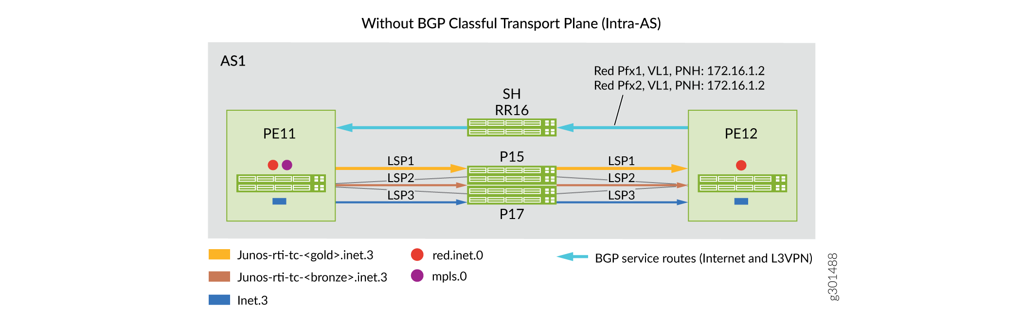
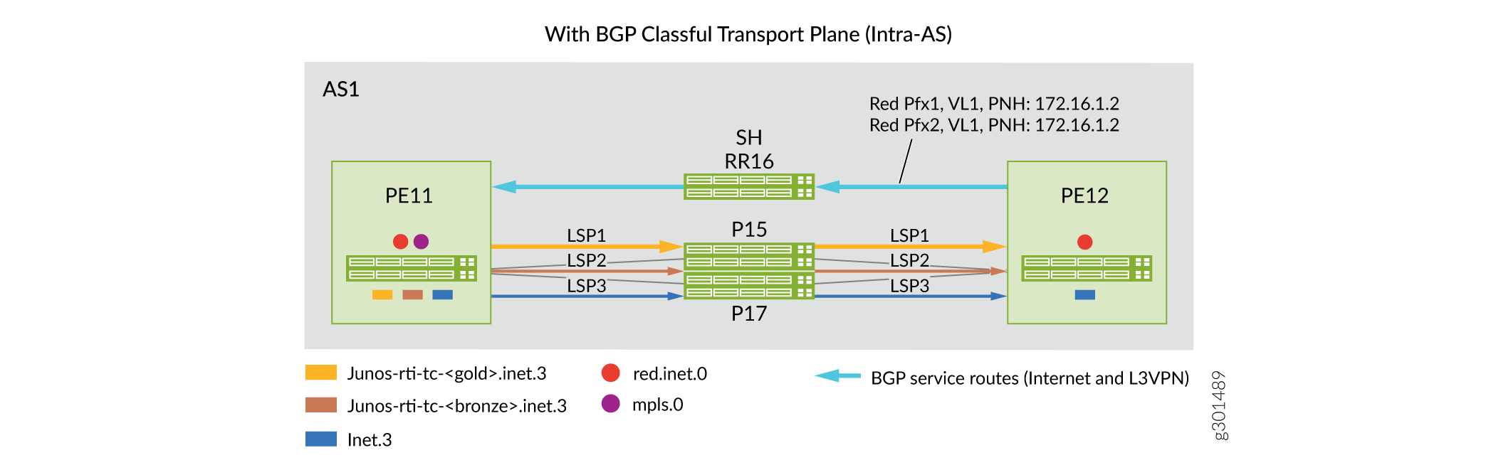
To classify transport tunnels into BGP transport class in an intra-AS setup:
- Define the transport class at the service node (ingress PE devices), for example, gold
and bronze, and assign color community values to the defined transport class.
Sample configuration:
pe11# show routing-options route-distinguisher-id 172.16.1.1; transport-class { name gold { color 100; } name bronze { color 200; - Associate the transport tunnel to a specific transport class at the ingress node of the
tunnels.
Sample configuration:
pe11# show protocols mpls
label-switched-path toPE12-bronze {
    transport-class bronze;
}
label-switched-path toPE12-gold {
    transport-class gold;
}
Intra-AS BGP classful transport plane functionality:
- BGP classful transport creates predefined transport RIBs per named transport class (gold and bronze) and auto derives mapping community from its color value (100 and 200).
- Intra-AS transport routes are populated in transport RIBs by the tunneling protocol when
it is associated with a transport class.
In this example, RSVP LSP routes associated with transport class gold (color 100) and transport class bronze (color 200) are installed in the transport RIBs junos-rti-tc-<100>.inet.3 and junos-rti-tc-<200>.inet.3, respectively.
- Service node (ingress PEs) match extended color community (color:0:100 and color:0:200) of service route against the mapping community in predefined resolution RIBs and resolve the protocol next hop (PNH) in corresponding transport RIBs (either junos-rti-tc-<100>.inet.3, or junos-rti-tc-<200>.inet.3).
- BGP routes bind to a resolution scheme by carrying the assiocaited mapping community.
- Each transport class automatically creates two predefined resolution schemes and
automatically derives the mapping community.
One resolution scheme is for resolving service routes that use Color:0:<val> as the mapping community.
The other resolution scheme is for resolving transport routes that use Transport-Target:0:<val> as the mapping community.
- If service route PNH cannot be resolved using RIBs listed in the predefined resolution scheme, then it can fall back to the inet.3 routing table.
- You can also configure fallback between different colored transport RIBs by using user-defined resolution schemes under the [edit routing-options resolution scheme] configuration hierarchy.
Inter-AS Implementation of BGP Classful Transport Planes
In an inter-AS network, BGP-LU is converted to BGP classful transport network after configuring a minimum of two transport classes (gold and bronze) on all service nodes or PE devices and border nodes (ABRs and ASBRs).
To convert the transport tunnels into BGP classful transport:
- Define transport class at the service nodes (ingress PE devices) and the border nodes
(ABRs and ASBRs), for example, gold and broze.
Sample configuration:
pe11# show routing-options route-distinguisher-id 172.16.1.1; transport-class { name gold { color 100; } name bronze { color 200; - Associate the transport tunnels to a specific transport class at the ingress node of the
tunnels (ingress PEs, ABRs,and ASBRs).
Sample configuration:
For RSVP LSPs
abr23# show protocols mpls
label-switched-path toASBR21-bronze {
    transport-class bronze;
}
label-switched-path toASBR22-gold {
    transport-class gold;
For IS-IS flxible algorithm
asbr13# show routing-options flex-algorithm 128 { … color 100; use-transport-class; } flex-algorithm 129 { … color 200; use-transport-class; } - Enable new family for the BGP classful transport (inet transport) and BGP-LU (inet
labeled-unicast) in the network.
Sample configuration:
abr23# show protocols bgp group toAs2-RR27 { family inet { labeled-unicast { … } transport { … } cluster 172.16.2.3; neighbor 172.16.2.7; } - Advertise service routes from the egress PE device with appropriate extended color
community.
Sample configuration:
pe11# show policy-options policy-statement red
term 1 {
        from {
            route-filter 192.168.3.3/32 exact;
        }
        then {
            community add map2gold;
            next-hop self;
            accept;
        }
    }
    term 2 {
        from {
            route-filter 192.168.33.33/32 exact;
        }
        then {
            community add map2bronze;
            next-hop self;
            accept;
        }
    }
community map2bronze members color:0:200;
community map2gold members color:0:100;
Inter-AS BGP classful transport plane functionality:
- BGP classful transport planes create predefined transport RIBs per named transport class (gold and bronze) and automatically derives mapping community from its color value.
-
Intra-AS transport routes are populated in transport RIBs by tunneling protocols when associated with a transport class.
For example, transport tunnel routes associated with the transport class gold and bronze are installed in the transport RIBs junos-rti-tc-<100>.inet.3 and junos-rti-tc-<200>.inet.3, respectively.
- BGP classful transport planes use unique Route Distinguisher and Route Target when it copies the transport tunnel routes from each transport RIB to the bgp.transport.3 routing table.
- Border nodes advertise routes from bgp.transport.3 routing table to its peers in other domains if family inet transport is negotiated in the BGP session.
- Receiving border node installs these bgp-ct routes in the bgp.transport.3 routing table and copies these routes based on the transport Route Target to the appropriate transport RIBs.
- Service node matches the color community in the service route against a mapping community in the resolution schemes and resolves PNH in the corresponding transport RIB (either junos-rti-tc-<100>.inet.3, or junos-rti-tc-<200>.inet.3).
- Border nodes use predefined resolution schemes for transport route PNH resolution.
- Predefined or user defined, both resolution schemes support service route PNH resolution. Predefined uses inet.3 as fallback, and user-defined resolution scheme allows list of transport RIBs to be used in the order specified while resolving PNH.
- If service route PNH cannot be resolved using RIBs listed in the user-defined resolution scheme, then route is discarded.
Improving Traffic Engineering Database Accuracy with RSVP PathErr Messages
An essential element of RSVP-based traffic engineering is the traffic engineering database. The traffic engineering database contains a complete list of all network nodes and links participating in traffic engineering, and a set of attributes each of those links can hold. (For more information about the traffic engineering database, see Constrained-Path LSP Computation.) One of the most important link attributes is bandwidth.
Bandwidth availability on links changes quickly as RSVP LSPs are established and terminated. It is likely that the traffic engineering database will develop inconsistencies relative to the real network. These inconsistencies cannot be fixed by increasing the rate of IGP updates.
Link availability can share the same inconsistency problem. A link that becomes unavailable can break all existing RSVP LSPs. However, its unavailability might not readily be known by the network.
When you configure the rsvp-error-hold-time statement,
a source node (ingress of an RSVP LSP) learns from the failures of
its LSP by monitoring PathErr messages transmitted from downstream
nodes. Information from the PathErr messages is incorporated into
subsequent LSP computations, which can improve the accuracy and speed
of LSP setup. Some PathErr messages are also used to update traffic
engineering database bandwidth information, reducing inconsistencies
between the traffic engineering database and the network.
You can control the frequency of IGP updates by using the update-threshold statement. See Configuring the RSVP Update Threshold on an Interface.
This section discusses the following topics:
- PathErr Messages
- Identifying the Problem Link
- Configuring the Router to Improve Traffic Engineering Database Accuracy
PathErr Messages
PathErr messages report a wide variety of problems by means of different code and subcode numbers. You can find a complete list of these PathErr messages in RFC 2205, Resource Reservation Protocol (RSVP), Version 1, Functional Specification and RFC 3209, RSVP-TE: Extensions to RSVP for LSP Tunnels.
When you configure the rsvp-error-hold-time statement,
two categories of PathErr messages, which specifically represent link
failures, are examined:
Link bandwidth is low for this LSP: Requested bandwidth unavailable—code 1, subcode 2
This type of PathErr message represents a global problem that affects all LSPs transiting the link. They indicate that the actual link bandwidth is lower than that required by the LSP, and that it is likely that the bandwidth information in the traffic engineering database is an overestimate.
When this type of error is received, the available link bandwidth is reduced in the local traffic engineering database, affecting all future LSP computations.
Link unavailable for this LSP:
Admission Control failure—code 1, any subcode except 2
Policy Control failures—code 2
Service Preempted—code 12
Routing problem—no route available toward destination—code 24, subcode 5
These types of PathErr messages are generally pertinent to the specified LSP. The failure of this LSP does not necessarily imply that other LSPs could also fail. These errors can indicate maximum transfer unit (MTU) problems, service preemption (either manually initiated by the operator or by another LSP with a higher priority), that a next-hop link is down, that a next-hop neighbor is down, or service rejection because of policy considerations. It is best to route this particular LSP away from the link.
Identifying the Problem Link
Each PathErr message includes the sender’s IP address. This information is propagated unchanged toward the ingress router. A lookup in the traffic engineering database can identify the node that originated the PathErr message.
Each PathErr message carries enough information to identify the RSVP session that triggered the message. If this is a transit router, it simply forwards the message. If this router is the ingress router (for this RSVP session), it has the complete list of all nodes and links the session should traverse. Coupled with the originating node information, the link can be uniquely identified.
Configuring the Router to Improve Traffic Engineering Database Accuracy
To improve the accuracy of the traffic engineering database,
configure the rsvp-error-hold-time statement. When this
statement is configured, a source node (ingress of an RSVP LSP) learns
from the failures of its LSP by monitoring PathErr messages transmitted
from downstream nodes. Information from the PathErr messages is incorporated
into subsequent LSP computations, which can improve the accuracy and
speed of LSP setup. Some PathErr messages also are used to update
traffic engineering database bandwidth information, reducing inconsistencies
between the traffic engineering database and the network.
To configure how long MPLS should remember RSVP PathErr messages
and consider them in CSPF computation, include the rsvp-error-hold-time statement:
rsvp-error-hold-time seconds;
You can include this statement at the following hierarchy levels:
[edit protocols mpls][edit logical-systems logical-system-name protocols mpls]
The time can be a value from 1 to 240 seconds. The default is 25 seconds. Configuring a value of 0 disables the monitoring of PathErr messages.
Change History Table
Feature support is determined by the platform and release you are using. Use Feature Explorer to determine if a feature is supported on your platform.