Service Sets for Static Endpoint IPsec Tunnels
Service Sets
The Adaptive Services PIC supports two types of service sets when you configure IPSec tunnels. Because they are used for different purposes, it is important to know the differences between these service set types.
Next-hop service set—Supports multicast and multicast-style dynamic routing protocols (such as OSPF) over IPSec. Next-hop service sets allow you to use inside and outside logical interfaces on the Adaptive Services PIC to connect with multiple routing instances. They also allow the use of Network Address Translation (NAT) and stateful firewall capabilities. However, next-hop service sets do not monitor Routing Engine traffic by default and require configuration of multiple service sets to support traffic from multiple interfaces.
Interface service set—Applied to a physical interface and similar to a stateless firewall filter. They are easy to configure, can support traffic from multiple interfaces, and can monitor Routing Engine traffic by default. However, they cannot support dynamic routing protocols or multicast traffic over the IPSec tunnel.
In general, we recommend that you use next-hop service sets because they support routing protocols and multicast over the IPSec tunnel, they are easier to understand, and the routing table makes forwarding decisions without administrative intervention.
See Also
Configuring IPsec Service Sets
IPsec service sets require additional specifications that you
configure at the [edit services service-set service-set-name ipsec-vpn-options] hierarchy level:
[edit services service-set service-set-name ipsec-vpn-options]
anti-replay-window-size bits;
clear-dont-fragment-bit;
copy-dont-fragment-bit
set-dont-fragment-bit
ike-access-profile profile-name;
local-gateway address <gw-interface interface-name.logical-unit-number>;
no-anti-replay;
no-certificate-chain-in-ike;
passive-mode-tunneling;
trusted-ca [ ca-profile-names ];
tunnel-mtu bytes;
Configuration of these statements is described in the following sections:
- Configuring the Local Gateway Address for IPsec Service Sets
- Configuring IKE Access Profiles for IPsec Service Sets
- Configuring Certification Authorities for IPsec Service Sets
- Configuring or Disabling Antireplay Service
- Clearing the Do Not Fragment Bit
- Configuring Passive-Mode Tunneling
- Configuring the Tunnel MTU Value
- Configuring IPsec Multipath Forwarding with UDP Encapsulation
Configuring the Local Gateway Address for IPsec Service Sets
If you configure an IPsec service set, you must also configure
a local IPv4 or IPv6 address by including the local-gateway statement:
If the Internet Key Exchange (IKE) gateway IP address is in inet.0 (the default situation), you configure the following statement:
local-gateway address;
If the IKE gateway IP address is in a VPN routing and forwarding (VRF) instance, you configure the following statement:
local-gateway address routing-instance instance-name;
You can configure all the link-type tunnels that share the same
local gateway address in a single next-hop-style service set. You
must specify a value for the inside-service-interface statement
at the [edit services service-set service-set-name] hierarchy level that matches the ipsec-inside-interface value, which you configure at the [edit services ipsec-vpn
rule rule-name term term-name from] hierarchy level. For more information about IPsec configuration,
see Configuring IPsec Rules.
Starting in Junos OS Release
16.1, to configure link-type tunnels, (i.e., next-hop style), for
HA purposes, you can configure AMS logical interfaces as the IPsec
internal interfaces by using the ipsec-inside-interface interface-name statement at the [edit services
ipsec-vpn rule rule-name term term-name from] hierarchy level.
Starting in Junos OS Release 17.1, AMS supports IPSec tunnel distribution.
- IKE Addresses in VRF Instances
- Clearing SAs When Local Gateway Address or MS-MPC or MS-MIC Goes Down
IKE Addresses in VRF Instances
You can configure Internet Key Exchange (IKE) gateway IP addresses that are present in a VPN routing and forwarding (VRF) instance as long as the peer is reachable through the VRF instance.
For next-hop service sets, the key management process (kmd)
places the IKE packets in the routing instance that contains the outside-service-interface value you specify, as in this example:
routing-instances vrf-nxthop {
    instance-type vrf;
    interface sp-1/1/0.2;
    ...
}
services service-set service-set-1 {
    next-hop-service {
        inside-service-interface sp-1/1/0.1;
        outside-service-interface sp-1/1/0.2;
    }
    ...
}
For interface service sets, the service-interface statement determines the VRF, as in this example:
routing-instances vrf-intf {
    instance-type vrf;
    interface sp-1/1/0.3;
    interface ge-1/2/0.1; # interface on which service set is applied
    ...
}
services service-set service-set-2 {
    interface-service {
        service-interface sp-1/1/0.3;
    }
    ...
}
Clearing SAs When Local Gateway Address or MS-MPC or MS-MIC Goes Down
Starting in Junos OS
Release 17.2R1, tou can use the gw-interface statement
to enable the cleanup of IKE triggers and IKE and IPsec SAs when an
IPsec tunnel’s local gateway IP address goes down, or the MS-MIC
or MS-MPC being used in the tunnel’s service set goes down.
local-gateway address <gw-interface interface-name.logical-unit-number>;
The interface-name and logical-unit-number must match the interface and logical unit on which the local gateway IP address is configured.
If the local gateway IP address for an IPsec tunnel’s service set goes down or the MS-MIC or MS-MPC that is being used in the service set goes down, the service set no longer sends IKE triggers. In addition, when the local gateway IP address goes down, the IKE and IPsec SAs are cleared for next-hop service sets, and go to the Not Installed state for interface-style service sets. The SAs that have the Not Installed state are deleted when the local gateway IP address comes back up.
If the local gateway IP address that goes down for a next-hop service set is for the responder peer, then you need to clear the IKE and IPsec SAs on the initiator peer so that the IPsec tunnel comes back up once the local gateway IP address comes back up. You can either manually clear the IKE and IPsec SAs on the initiator peer (see clear services ipsec-vpn ike security-associations and clear services ipsec-vpn ipsec security-associations) or enable dead peer detection on the initiator peer (see Configuring Stateful Firewall Rules).
Configuring IKE Access Profiles for IPsec Service Sets
For dynamic endpoint tunneling only, you need to reference the
IKE access profile configured at the [edit access] hierarchy
level. To do this, include the ike-access-profile statement
at the [edit services service-set service-set-name ipsec-vpn-options] hierarchy level:
[edit services service-set service-set-name ipsec-vpn-options]
ike-access-profile profile-name;
The ike-access-profile statement must reference the
same name as the profile statement you configured for IKE
access at the [edit access] hierarchy level. You can reference
only one access profile in each service set. This profile is used
to negotiate IKE and IPsec security associations with dynamic peers
only.
If you configure an IKE access profile in a service set, no
other service set can share the same local-gateway address.
Also, you must configure a separate service set for each VRF.
All interfaces referenced by the ipsec-inside-interface statement within a service set must belong to the same VRF.
Configuring Certification Authorities for IPsec Service Sets
You can specify one or more trusted certification authorities
by including the trusted-ca statement:
trusted-ca [ ca-profile-names ];
When you configure public key infrastructure (PKI) digital certificates
in the IPsec configuration, each service set can have its own set
of trusted certification authorities. The names you specify for the trusted-ca statement must match profiles configured at the [edit security pki] hierarchy level; for more information,
see the Junos OS Administration Library for Routing Devices. For more information about IPsec
digital certificate configuration, see Configuring IPsec
Rules.
Starting in Junos OS
Release 18.2R1, you can configure the MX Series router with MS-MPCs
or MS-MICs to send only the end-entity certificate for certificate-based
IKE authentication instead of the full certificate chain. This avoids IKE fragmentation. To configure this feature, include
the no-certificate-chain-in-ike statement:
[edit services service-set service-set-name ipsec-vpn-options]
no-certificate-chain-in-ike;
Configuring or Disabling Antireplay Service
You can include the anti-replay-window-size statement
at the [edit services service-set service-set-name ipsec-vpn-options] hierarchy level to specify the size of
the antireplay window.
anti-replay-window-size bits;
This statement is useful for dynamic endpoint tunnels for which
you cannot configure the anti-replay-window-size statement
at the [edit services ipsec-vpn rule rule-name term term-name then] hierarchy level.
For static IPsec tunnels, this statement sets the antireplay
window size for all the static tunnels within this service set. If
a particular tunnel needs a specific value for antireplay window
size, set the anti-replay-window-size statement at the [edit services ipsec-vpn rule rule-name term term-name then] hierarchy level. If antireplay check
has to be disabled for a particular tunnel in this service set, set
the no-anti-replay statement at the [edit services
ipsec-vpn rule rule-name term term-name then] hierarchy level.
The anti-replay-window-size and no-anti-replay settings at the [edit services ipsec-vpn rule rule-name term term-name then] hierarchy level
override the settings specified at the [edit services service-set service-set-name ipsec-vpn-options] hierarchy level.
You can also include the no-anti-replay statement
at the [edit services service-set service-set-name ipsec-vpn-options] hierarchy level to disable IPsec antireplay
service. It occasionally causes interoperability issues for security
associations.
no-anti-replay;
This statement is useful for dynamic endpoint tunnels for which
you cannot configure the no-anti-reply statement at the [edit services ipsec-vpn rule rule-name term term-name then] hierarchy level.
For static IPsec tunnels, this statement disables the antireplay
check for all the tunnels within this service set. If antireplay
check has to be enabled for a particular tunnel, then set the anti-replay-window-size statement at the [edit services
ipsec-vpn rule rule-name term term-name then] hierarchy level.
Setting the anti-replay-window-size and no-anti-replay statements at the [edit services ipsec-vpn rule rule-name term term-name then] hierarchy level
overrides the settings specified at the [edit services service-set service-set-name ipsec-vpn-options] hierarchy level.
Clearing the Do Not Fragment Bit
You can include the clear-dont-fragment-bit statement
at the [edit services service-set service-set-name ipsec-vpn-options] hierarchy level to clear the do not fragment
(DF) bit on all IP version 4 (IPv4) packets entering the IPsec
tunnel. If the encapsulated packet size exceeds the tunnel maximum
transmission unit (MTU), the packet is fragmented before encapsulation.
clear-dont-fragment-bit;
This statement is useful for dynamic endpoint tunnels for which
you cannot configure the clear-dont-fragment-bit statement
at the [edit services ipsec-vpn rule rule-name term term-name then] hierarchy level.
For static IPsec tunnels, setting this statement clears the
DF bit on packets entering all the static tunnels within this service
set. If you want to clear the DF bit on packets entering a specific
tunnel, set the clear-dont-fragment-bit statement at the [edit services ipsec-vpn rule rule-name term term-name then] hierarchy level.
Starting in Junos OS Release 14.1, in packets that
are transmitted through dynamic endpoint IPSec tunnels, you can enable
the value set in the DF bit of the packet entering the tunnel to be
copied only to the outer header of the IPsec packet and to not cause
any modification to the DF bit in the inner header of the IPsec packet. If the packet size exceeds the tunnel maximum transmission unit
(MTU) value, the packet is fragmented before encapsulation. For IPsec
tunnels, the default MTU value is 1500 regardless of the interface
MTU setting. To copy the DF bit value to only the outer header and
not modify the inner header, use the copy-dont-fragment-bit statement at the [edit services service-set service-set-name ipsec-vpn-options] hierarchy level. You can also configure
the DF bit to be set only in the outer IPv4 header of the IPsec packet
and not be defined in the inner IPv4 header. To configure the DF bit
in only the outer header of the IPsec packet and to leave the inner
header unmodified, include the set-dont-fragment-bit statement
at the [edit services service-set service-set-name ipsec-vpn-options] hierarchy level. These settings apply for
dynamic endpoint tunnels and not for static tunnels, for which you
need to include the copy-dont-fragment-bit and set-dont-fragment-bit statements at the [edit services ipsec-vpn rule rule-name term term-name then] hierarchy level
to clear the DF bit in the IPv4 packets that enter the static tunnel.
These functionalities are supported on MX Series routers with MS-MICs
and MS-MPCs.
Configuring Passive-Mode Tunneling
You can include the passive-mode-tunneling statement
at the [edit services service-set service-set-name ipsec-vpn-options] hierarchy level to enable the service set
to tunnel malformed packets.
[edit services service-set service-set-name ipsec-vpn-options]
passive-mode-tunneling;
This functionality bypasses the active IP checks, such as version, TTL, protocol, options, address and other land attack checks, and tunnels the packets as is. If this statement is not configured, packets failing the IP checks are dropped in the PIC. In passive mode, the inner packet is not touched; an ICMP error is not generated if the packet size exceeds the tunnel MTU value.
The IPsec tunnel is not treated as a next hop and TTL is not decremented. Because an ICMP error is not generated if the packet size exceeds the tunnel MTU value, the packet is tunnelled even if it crosses the tunnel MTU threshold.
This functionality is similar to that provided by the no-ipsec-tunnel-in-traceroute statement, described in Tracing Junos VPN Site Secure Operations. Starting in Junos OS Release 14.2, passive mode tunneling
is supported on MS-MICs and MS-MPCs.
Starting in Junos OS Release
14.2, the header-integrity-check option that is supported
on MS-MICs and MS-MPCs to verify the packet header for anomalies in
IP, TCP, UDP, and ICMP information and flag such anomalies and errors
has a functionality that is opposite to the functionality caused by
passive mode tunneling. If you configure
both the header-integrity-check statement and the passive-mode tunneling statement on MS-MICs and MS-MPCs, and
attempt to commit such a configuration, an error is displayed during
commit.
The passive mode tunneling functionality (by including the passive-mode-tunnelin statement at the [edit services
service-set service-set-name ipsec-vpn-options] hierarchy level) is a superset of the capability to disable IPsec
tunnel endpoint in the traceroute output (by including no-ipsec-tunnel-in-traceroute statement at the [edit services ipsec-vpn] hierarchy
level). Passive mode tunneling also bypasses the active IP checks
and tunnel MTU check in addition to not treating an IPsec tunnel
as a next-hop as configured by the no-ipsec-tunnel-in-traceroute statement.
Configuring the Tunnel MTU Value
You can include the tunnel-mtu statement at the [edit services service-set service-set-name ipsec-vpn-options] hierarchy level to set the maximum transmission unit (MTU) value
for IPsec tunnels.
tunnel-mtu bytes;
This statement is useful for dynamic endpoint tunnels for which
you cannot configure the tunnel-mtu statement at the [edit services ipsec-vpn rule rule-name term term-name then] hierarchy level.
For static IPsec tunnels, this statement sets the tunnel MTU
value for all the tunnels within this service set. If you need a
specific value for a particular tunnel, then set the tunnel-mtu statement at the [edit services ipsec-vpn rule rule-name term term-name then] hierarchy level.
The tunnel-mtu setting at the [edit services
ipsec-vpn rule rule-name term term-name then] hierarchy level overrides the value specified at the [edit services service-set service-set-name ipsec-vpn-options] hierarchy level.
Configuring IPsec Multipath Forwarding with UDP Encapsulation
Starting in Junos OS Release 16.1, you can enable multipath forwarding of IPsec traffic by configuring UDP encapsulation in the service set, which adds a UDP header to the IPsec encapsulation of packets. This results in the forwarding of IPsec traffic over multiple paths, increasing the throughput of IPsec traffic. If you do not enable UDP encapsulation, all the IPsec traffic follows a single forwarding path.
When NAT-T is detected, only NAT-T UDP encapsulation occurs, not the UDP encapsulation for IPsec packets.
To enable UDP encapsulation:
Enable UDP encapsulation.
[edit services service-set service-set-name ipsec-vpn-options] user@host set udp-encapsulation
(Optional) Specify the UDP destination port number.
[edit services service-set service-set-name ipsec-vpn-options udp-encapsulation]
user@host set udp-dest-port destination-port
Use a destination port number from 1025 through 65536, but do not use 4500. If you do not specify a port number, the default destination port is 4565.
See Also
Example: IKE Dynamic SA Configuration with Digital Certificates
This example shows how to configure IKE dynamic SA with digital certificates and contains the following sections.
Requirements
This example uses the following hardware and software components:
Four M Series, MX Series, or T Series routers with multiservices interfaces installed in them.
Junos OS Release 9.4 or later.
Before you configure this example you must request a CA certificate, create a local certificate, and load these digital certificates into the router. For details, see Enroll a Certificate.
Overview
A security association (SA) is a simplex connection that enables two hosts to securely communicate with each other using IPsec. This example explains IKE dynamic SA configuration with digital certificates. The use of digital certificates provides additional security to your IKE tunnel. Using default values in the Services PIC, you do not need to configure an IPsec proposal or IPsec policy. However, you must configure an IKE proposal that specifies the use of digital certificates, reference the IKE proposal and local certificate in an IKE policy, and apply the CA profile to the service set.
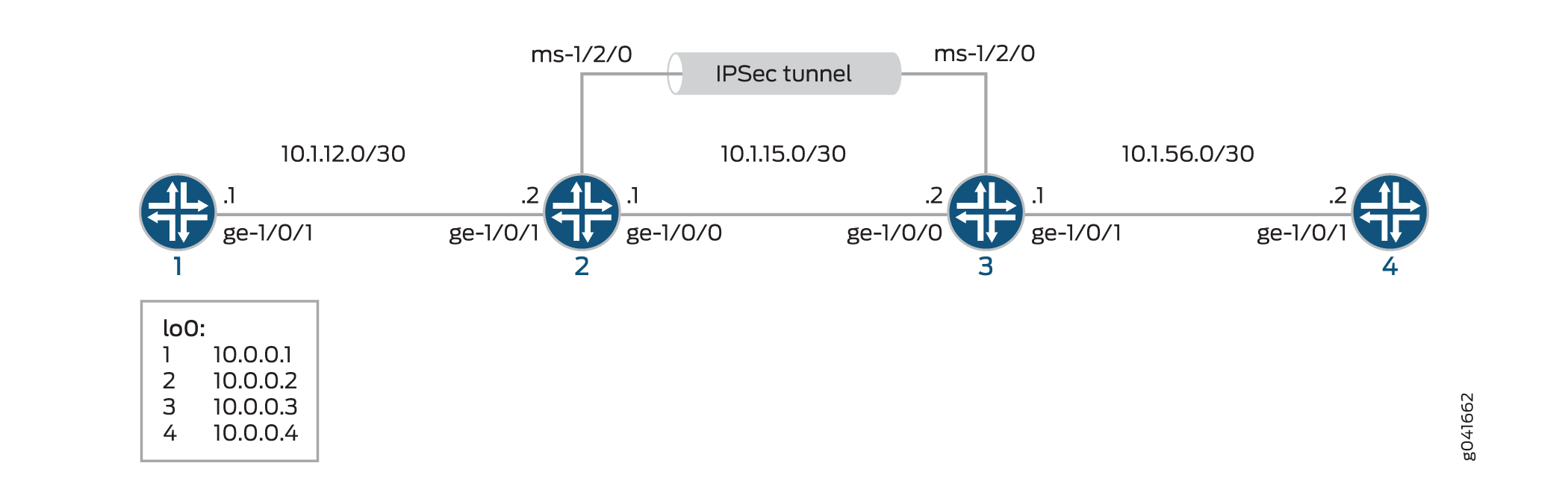
Figure 1 shows an IPsec topology containing a group of four routers. This configuration requires Routers 2 and 3 to establish an IKE-based IPsec tunnel by using digital certificates in place of preshared keys. Routers 1 and 4 provide basic connectivity and are used to verify that the IPsec tunnel is operational.
Topology
Configuration
To configure IKE dynamic SA with digital certificates, perform these tasks:
The interface types shown in this example are for indicative
purpose only. For example, you can use so- interfaces instead
of ge- and sp- instead of ms-.
Configuring Router 1
CLI Quick Configuration
To quickly configure this example, copy the following commands, paste them into a text file, remove any line breaks, change any details necessary to match your network configuration, and then copy and paste the commands into the CLI, at the [edit] hierarchy level, of Router 1.
set interfaces ge-0/0/0 description "to R2 ge-0/0/0"
set interfaces ge-0/0/0 unit 0 family inet address 10.1.12.2/30
set interfaces lo0 unit 0 family inet address 10.0.0.1/32
set routing-options router-id 10.0.0.1
set protocols ospf area 0.0.0.0 interface ge-0/0/0
set protocols ospf area 0.0.0.0 interface lo0.0
Step-by-Step Procedure
The following example requires you to navigate various levels in the configuration hierarchy. For information about navigating the CLI, see Using the CLI Editor in Configuration Mode in the CLI User Guide.
To configure Router 1 for OSPF connectivity with Router 2:
Configure an Ethernet interface and the loopback interface.
[edit interfaces]
user@router1# set ge-0/0/0 description "to R2 ge-0/0/0"
user@router1# set ge-0/0/0 unit 0 family inet address 10.1.12.2/30
user@router1# set lo0 unit 0 family inet address 10.0.0.1/32
Specify the OSPF area and associate the interfaces with the OSPF area.
[edit protocols]
user@router1# set ospf area 0.0.0.0 interface ge-0/0/0.0
user@router1# set ospf area 0.0.0.0 interface lo0.0
Configure the router ID.
[edit routing-options]
user@router1# set router-id 10.0.0.1
Commit the configuration.
[edit]
user@router1# commit
Results
From the configuration mode, confirm your configuration
by entering the show interfaces, show protocols ospf, and show routing-options commands. If the output does
not display the intended configuration, repeat the instructions in
this example to correct the configuration.
user@router1# show interfaces
interfaces {
    ge-0/0/0 {
        description "To R2 ge-0/0/0";
        unit 0 {
            family inet {
                address 10.1.12.2/30;
            }
        }
    }
    lo0 {
        unit 0 {
            family inet {
                address 10.0.0.1/32;
            }
        }
    }
}
user@router1# show protocols ospf
protocols {
    ospf {
        area 0.0.0.0 {
            interface ge-0/0/0.0;
            interface lo0.0;
        }
    }
}
user@router1# show routing-options
routing-options  {
    router-id 10.0.0.1;
}
Configuring Router 2
CLI Quick Configuration
To quickly configure this example, copy the following commands, paste them into a text file, remove any line breaks, change any details necessary to match your network configuration, and then copy and paste the commands into the CLI, at the [edit] hierarchy level, of Router 2.
set interfaces ge-0/0/0 description "to R1 ge-0/0/0"
set interfaces ge-0/0/0 unit 0 family inet address 10.1.12.1/30
set interfaces ge-0/0/1 description "to R3 ge-0/0/1"
set interfaces ge-0/0/1 unit 0 family inet address 10.1.15.1/30
set interfaces ms-1/2/0 services-options syslog host local services info
set interfaces ms-1/2/0 unit 0 family inet
set interfaces ms-1/2/0 unit 1 family inet
set interfaces ms-1/2/0 unit 1 service-domain inside
set interfaces ms-1/2/0 unit 2 family inet
set interfaces ms-1/2/0 unit 2 service-domain outside
set interfaces lo0 unit 0 family inet address 10.0.0.2/32
set protocols ospf area 0.0.0.0 interface ge-0/0/0.0
set protocols ospf area 0.0.0.0 interface lo0.0
set protocols ospf area 0.0.0.0 interface ms-1/2/0.1
set routing-options router-id 10.0.0.2
set services ipsec-vpn rule rule-ike term term-ike then remote-gateway 10.1.15.2
set services ipsec-vpn rule rule-ike term term-ike then dynamic ike-policy ike-digital-certificates
set services ipsec-vpn rule rule-ike term term-ike then dynamic ipsec-policy ipsec-demo-policy
set services ipsec-vpn rule match-direction input
set services ipsec-vpn ike proposal ike-demo-proposal authentication-method rsa-signatures
set services ipsec-vpn ike policy ike-digital-certificates proposals ike-demo-proposal
set services ipsec-vpn ike policy ike-digital-certificates local-id fqdn router2.example.com
set services ipsec-vpn ike policy ike-digital-certificates local-certificate local-entrust2
set services ipsec-vpn ike policy ike-digital-certificates remote-id fqdn router3.example.com
set services ipsec-vpn ipsec proposal ipsec-demo-proposal protocol esp
set services ipsec-vpn ipsec proposal ipsec-demo-proposal authentication-algorithm hmac-sha1-96
set services ipsec-vpn ipsec proposal ipsec-demo-proposal encryption-algorithm 3des-cbc
set services ipsec-vpn ipsec policy ipsec-demo-policy perfect-forward-secrecy keys group2
set services ipsec-vpn ipsec proposals ipsec-demo-proposal
set services ipsec-vpn establish-tunnels immediately
set services service-set demo-service-set next-hop-service inside-service-interface ms-1/2/0.1
set services service-set demo-service-set next-hop-service outside-service-interface ms-1/2/0.2
set services service-set demo-service-set ipsec-vpn-options trusted-ca entrust
set services service-set demo-service-set ipsec-vpn-options local-gateway 10.1.15.1
set services service-set demo-service-set ipsec-vpn-rules rule-ike
Step-by-Step Procedure
The following example requires you to navigate various levels in the configuration hierarchy. For information about navigating the CLI, see Using the CLI Editor in Configuration Mode in the CLI User Guide.
To configure OSPF connectivity and IPsec tunnel parameters on Router 2:
Configure interface properties. In this step, you configure two Ethernet interfaces (ge-1/0/0 and ge-1/0/1), the loopback interface and a multiservices interface (ms-1/2/0).
[edit interfaces]
user@router2# set ge-0/0/0 description "to R1 ge-0/0/0"
user@router2# set ge-0/0/0 unit 0 family inet address 10.1.12.1/30
user@router2# set ge-0/0/1 description "to R3 ge-0/0/1"
user@router2# set ge-0/0/1 unit 0 family inet address 10.1.15.1/30
user@router2# set ms-1/2/0 services-options syslog host local services info
user@router2# set ms-1/2/0 unit 0 family inet
user@router2# set ms-1/2/0 unit 1 family inet
user@router2# set ms-1/2/0 unit 1 service-domain inside
user@router2# set ms-1/2/0 unit 2 family inet
user@router2# set ms-1/2/0 unit 2 service-domain outside
user@router2# set lo0 unit 0 family inet address 10.0.0.2/32
Specify the OSPF area and associate the interfaces with the OSPF area.
[edit protocols]
user@router2# set ospf area 0.0.0.0 interface ge-0/0/0.0
user@router2# set ospf area 0.0.0.0 interface lo0.0
user@router2# set ospf area 0.0.0.0 interface ms-1/2/0.1
Configure the router ID.
[edit routing-options]
user@router2# set router-ID 10.0.0.2
Configure an IKE proposal and policy. To enable an IKE proposal for digital certificates, include the
rsa-signaturesstatement at the[edit services ipsec-vpn ike proposal proposal-name authentication-method]hierarchy level. To reference the local certificate in the IKE policy, include thelocal-certificatestatement at the[edit services ipsec-vpn ike policy policy-name]hierarchy level. To identify the CA or RA in the service set, include thetrusted-castatement at the[edit services service-set service-set-name ipsec-vpn-options]hierarchy level.Note:For information about creating and installing digital certificates, see Enroll a Certificate.
[edit services ipsec-vpn]
user@router2# set ike proposal ike-demo-proposal authentication-method rsa-signatures
user@router2# set ike policy ike-digital-certificates proposals ike-demo-proposal
user@router2# set ike policy ike-digital-certificates local-id fqdn router2.example.com
user@router2# set ike policy ike-digital-certificates local-certificate local-entrust2
user@router2# set ike policy ike-digital-certificates remote-id fqdn router3.example.com
Configure an IPsec proposal and policy. Also, set the
established-tunnelsknob toimmediately.[edit services ipsec-vpn] user@router2# set ipsec proposal ipsec-demo-proposal protocol esp user@router2# set ipsec proposal ipsec-demo-proposal authentication-algorithm hmac-sha1-96 user@router2# set ipsec proposal ipsec-demo-proposal encryption-algorithm 3des-cbc user@router2# set ipsec policy ipsec-demo-policy perfect-forward-secrecy keys group2 user@router2# set ipsec proposals ipsec-demo-proposal user@router2# set establish-tunnels immediately
Configure an IPsec rule.
[edit services ipsec-vpn]
user@router2# set rule rule-ike term term-ike then remote-gateway 10.1.15.2
user@router2# set rule rule-ike term term-ike then dynamic ike-policy ike-digital-certificates
user@router2# set rule rule-ike term term-ike then dynamic ipsec-policy ipsec-demo-policy
user@router2# set rule match-direction input
Configure a next-hop style service set, specify the local-gateway address, and associate the IPsec VPN rule with the service set.
[edit services]
user@router2# set service-set demo-service-set next-hop-service inside-service-interface ms-1/2/0.1
user@router2# set service-set demo-service-set next-hop-service outside-service-interface ms-1/2/0.2
user@router2# set service-set demo-service-set ipsec-vpn-options trusted-ca entrust
user@router2# set service-set demo-service-set ipsec-vpn-options local-gateway 10.1.15.1
user@router2# set service-set demo-service-set ipsec-vpn-rules rule-ike
Commit the configuration.
[edit]
user@router2# commit
Results
From the configuration mode, confirm your configuration
by entering the show interfaces, show protocols ospf, show routing-options, and show services commands.
If the output does not display the intended configuration, repeat
the instructions in this example to correct the configuration
user@router2# show interfaces
interfaces {
    ge-0/0/0 {
        description "To R1 ge-0/0/0";
        unit 0 {
            family inet {
                address 10.1.12.1/30;
            }
        }
    }

    ge-0/0/1 {
        description "To R3 ge-0/0/1";
        unit 0 {
            family inet {
                address 10.1.15.1/30;
            }
        }
    }

    ms-1/2/0 {
        services-options {
            syslog {
                host local {
                    services info;
                }
            }
        }
        unit 0 {
            family inet;
        }
        unit 1 {
            family inet;
            service-domain inside;
        }
        unit 2 {
            family inet;
            service-domain outside;
        }
    }
    lo0 {
        unit 0 {
            family inet {
                address 10.0.0.2/32;
            }
        }
    }
}
user@router2# show protocols ospf
protocols {
    ospf {
        area 0.0.0.0 {
            interface ge-0/0/0.0;
            interface lo0.0;
            interface ms-1/2/0.1;
        }
    }
}
user@router2# show routing-options
routing-options {
    router-id 10.0.0.2;
}
user@router2# show services
services {
    ipsec-vpn {
        rule rule-ike {
            term term-ike {
                then {
                    remote-gateway 10.1.15.2;
                    dynamic {
                        ike-policy ike-digital-certificates;
                        ipsec-policy ipsec-demo-policy
                    }
                }
            }
            match-direction input;
        }
        ike {
            proposal ike-demo-proposal {
                authentication-method rsa-signatures;
            }
            policy ike-digital-certificates {
                proposals ike-demo-proposal;
                local-id fqdn router2.example.com;
                local-certificate local-entrust2;
                remote-id fqdn router3.example.com;
            }
        }
        ipsec {
            proposal ipsec-demo-proposal {
                protocol esp;
                authentication-algorithm hmac-sha1-96;
                encryption-algorithm 3des-cbc;
            }
            policy demo-policy {
                perfect-forward-secrecy {
                    keys group2;
                }
                proposals ipsec-demo-proposal;
            }
            establish-tunnels immediately;
        }
        service-set service-set-dynamic-demo-service-set {
            next-hop-service {
                inside-service-interface ms-1/2/0.1;
                outside-service-interface ms-1/2/0.2;
            }
            ipsec-vpn-options {
                trusted-ca entrust;
                local-gateway 10.1.15.1;
            }
            ipsec-vpn-rules rule-ike;
        }
    }
}
Configuring Router 3
CLI Quick Configuration
To quickly configure this example, copy the following commands, paste them into a text file, remove any line breaks, change any details necessary to match your network configuration, and then copy and paste the commands into the CLI, at the [edit] hierarchy level, of Router 3.
set interfaces ge-0/0/0 description "to R4 ge-0/0/0"
set interfaces ge-0/0/0 unit 0 family inet address 10.1.56.1/30
set interfaces ge-0/0/1 description "to R2 ge-0/0/1"
set interfaces ge-0/0/1 unit 0 family inet address 10.1.15.2/30
set interfaces ms-1/2/0 services-options syslog host local services info
set interfaces ms-1/2/0 unit 0 family inet
set interfaces ms-1/2/0 unit 1 family inet
set interfaces ms-1/2/0 unit 1 service-domain inside
set interfaces ms-1/2/0 unit 2 family inet
set interfaces ms-1/2/0 unit 2 service-domain outside
set interfaces lo0 unit 0 family inet address 10.0.0.3/32
set protocols ospf area 0.0.0.0 interface ge-0/0/0.0
set protocols ospf area 0.0.0.0 interface lo0.0
set protocols ospf area 0.0.0.0 interface ms-1/2/0.1
set routing-options router-id 10.0.0.3
set services ipsec-vpn rule rule-ike term term-ike then remote-gateway 10.1.15.1
set services ipsec-vpn rule rule-ike term term-ike then dynamic ike-policy ike-digital-certificates
set services ipsec-vpn rule rule-ike term term-ike then dynamic ipsec-policy ipsec-demo-policy
set services ipsec-vpn rule match-direction input
set services ipsec-vpn ike proposal ike-demo-proposal authentication-method rsa-signatures
set services ipsec-vpn ike policy ike-digital-certificates proposals ike-demo-proposal
set services ipsec-vpn ike policy ike-digital-certificates local-id fqdn router3.example.com
set services ipsec-vpn ike policy ike-digital-certificates local-certificate local-entrust3
set services ipsec-vpn ike policy ike-digital-certificates remote-id fqdn router2.example.com
set services ipsec-vpn ipsec proposal ipsec-demo-proposal protocol esp
set services ipsec-vpn ipsec proposal ipsec-demo-proposal authentication-algorithm hmac-sha1-96
set services ipsec-vpn ipsec proposal ipsec-demo-proposal encryption-algorithm 3des-cbc
set services ipsec-vpn ipsec policy ipsec-demo-policy perfect-forward-secrecy keys group2
set services ipsec-vpn ipsec proposals ipsec-demo-proposal
set services ipsec-vpn establish-tunnels immediately
set services service-set demo-service-set next-hop-service inside-service-interface ms-1/2/0.1
set services service-set demo-service-set next-hop-service outside-service-interface ms-1/2/0.2
set services service-set demo-service-set ipsec-vpn-options trusted-ca entrust
set services service-set demo-service-set ipsec-vpn-options local-gateway 10.1.15.2
set services service-set demo-service-set ipsec-vpn-rules rule-ike
Step-by-Step Procedure
The following example requires you to navigate various levels in the configuration hierarchy. For information about navigating the CLI, see Using the CLI Editor in Configuration Mode in the CLI User Guide.
If the IPsec peers do not have a symmetrical configuration containing all the necessary components, they cannot establish a peering relationship. You need to request a CA certificate, create a local certificate, load these digital certificates into the router, and reference them in your IPsec configuration. For information about digital certification, see Enroll a Certificate.
To configure OSPF connectivity and IPsec tunnel parameters on Router 3:
Configure interface properties. In this step, you configure two Ethernet interfaces (ge-1/0/0 and ge-1/0/1), the loopback interface, and a multiservices interface (ms-1/2/0).
[edit interfaces]
user@router3# set ge-0/0/0 description "to R4 ge-0/0/0"
user@router3# set ge-0/0/0 unit 0 family inet address 10.1.56.1/30
user@router3# set ge-0/0/1 description "to R2 ge-0/0/1"
user@router3# set ge-0/0/1 unit 0 family inet address 10.1.15.2/30
user@router3# set ms-1/2/0 services-options syslog host local services info
user@router3# set ms-1/2/0 unit 0 family inet
user@router3# set ms-1/2/0 unit 1 family inet
user@router3# set ms-1/2/0 unit 1 service-domain inside
user@router3# set ms-1/2/0 unit 2 family inet
user@router3# set ms-1/2/0 unit 2 service-domain outside
user@router3# set lo0 unit 0 family inet address 10.0.0.3/32
Specify the OSPF area, associate the interfaces with the OSPF area.
[edit protocols]
user@router3# set ospf area 0.0.0.0 interface ge-0/0/0.0
user@router3# set ospf area 0.0.0.0 interface lo0.0
user@router3# set ospf area 0.0.0.0 interface ms-1/2/0.1
Configure a router ID.
[edit routing-options]
user@router3# set router-id 10.0.0.3
Configure an IKE proposal and policy. To enable an IKE proposal for digital certificates, include the
rsa-signaturesstatement at the[edit services ipsec-vpn ike proposal proposal-name authentication-method]hierarchy level. To reference the local certificate in the IKE policy, include thelocal-certificatestatement at the[edit services ipsec-vpn ike policy policy-name]hierarchy level. To identify the CA or RA in the service set, include thetrusted-castatement at the[edit services service-set service-set-name ipsec-vpn-options]hierarchy level.Note:For information about creating and installing digital certificates, see Enroll a Certificate.
[edit services ipsec-vpn]
user@router3# set ike proposal ike-demo-proposal authentication-method rsa-signatures
user@router3# set ike policy ike-digital-certificates proposals ike-demo-proposal
user@router3# set ike policy ike-digital-certificates local-id fqdn router2.example.com
user@router3# set ike policy ike-digital-certificates local-certificate local-entrust2
user@router3# set ike policy ike-digital-certificates remote-id fqdn router3.example.com
Configure an IPsec proposal. Also, set the
established-tunnelsknob toimmediately.[edit services ipsec-vpn] user@router3# set ipsec proposal ipsec-demo-proposal protocol esp user@router3# set ipsec proposal ipsec-demo-proposal authentication-algorithm hmac-sha1-96 user@router3# set ipsec proposal ipsec-demo-proposal encryption-algorithm 3des-cbc user@router3# set ipsec policy ipsec-demo-policy perfect-forward-secrecy keys group2 user@router3# set ipsec proposals ipsec-demo-proposal user@router3# set establish-tunnels immediately
Configure an IPsec rule.
[edit services ipsec-vpn]
user@router3# set rule rule-ike term term-ike then remote-gateway 10.1.15.2
user@router3# set rule rule-ike term term-ike then dynamic ike-policy ike-digital-certificates
user@router3# set rule rule-ike term term-ike then dynamic ipsec-policy ipsec-demo-policy
user@router3# set rule match-direction input
Configure a next-hop style service set, specify the local-gateway address, and associate the IPsec VPN rule with the service set.
[edit services]
user@router3# set service-set demo-service-set next-hop-service inside-service-interface ms-1/2/0.1
user@router3# set service-set demo-service-set next-hop-service outside-service-interface ms-1/2/0.2
user@router3# set service-set demo-service-set ipsec-vpn-options trusted-ca entrust
user@router3# set service-set demo-service-set ipsec-vpn-options local-gateway 10.1.15.2
user@router3# set service-set demo-service-set ipsec-vpn-rules rule-ike
Commit the configuration.
[edit]
user@router3# commit
Results
From the configuration mode, confirm your configuration
by entering the show interfaces, show protocols ospf, show routing-options, and show services commands.
If the output does not display the intended configuration, repeat
the instructions in this example to correct the configuration
user@router3# show interfaces
interfaces {
    ge-0/0/0 {
        description "To R4 ge-0/0/0";
        unit 0 {
            family inet {
                address 10.1.56.1/30;
            }
        }
    }
    ge-0/0/1 {
        description "To R2 ge-0/0/1";
        unit 0 {
            family inet {
                address 10.1.15.2/30;
            }
        }
    }
    ms-1/2/0 {
        services-options {
            syslog {
                host local {
                    services info;
                }
            }
        }
        unit 0 {
            family inet {
            }
            unit 1 {
                family inet;
                service-domain inside;
            }
            unit 2 {
                family inet;
                service-domain outside;
            }
        }
        lo0 {
            unit 0 {
                family inet {
                    address 10.0.0.3/32;
                }
            }
        }
    }
}
user@router3# show protocols ospf
protocols {
    ospf {
        area 0.0.0.0 {
            interface ge-0/0/0.0;
            interface lo0.0;
            interface ms-1/2/0.1;
        }
    }
}
user@router3# show routing-options
routing-options {
    router-id 10.0.0.3;
}
user@router3# show services
services {
    ipsec-vpn {
        rule rule-ike {
            term term-ike {
                then {
                    remote-gateway 10.1.15.1;
                    dynamic {
                        ike-policy ike-digital-certificates;
                        ipsec-policy ipsec-demo-policy
                    }
                }
            }
            match-direction input;
        }
        ike {
            proposal ike-demo-proposal {
                authentication-method rsa-signatures;
            }
            policy ike-digital-certificates {
                proposals ike-demo-proposal;
                local-id fqdn router3.example.com;
                local-certificate local-entrust3;
                remote-id fqdn router2.example.com;
            }
        }
        ipsec {
            proposal ipsec-demo-proposal {
                protocol esp;
                authentication-algorithm hmac-sha1-96;
                encryption-algorithm 3des-cbc;
            }
            policy demo-policy {
                perfect-forward-secrecy {
                    keys group2;
                }
                proposals ipsec-demo-proposal;
            }
            establish-tunnels immediately;
        }
        service-set service-set-dynamic-demo-service-set {
            next-hop-service {
                inside-service-interface ms-1/2/0.1;
                outside-service-interface ms-1/2/0.2;
            }
            ipsec-vpn-options {
                trusted-ca entrust;
                local-gateway 10.1.15.2;
            }
            ipsec-vpn-rules rule-ike;
        }
    }
}
Configuring Router 4
CLI Quick Configuration
To quickly configure this example, copy the following commands, paste them into a text file, remove any line breaks, change any details necessary to match your network configuration, and then copy and paste the commands into the CLI, at the [edit] hierarchy level, of Router 4.
set interfaces ge-0/0/0 description "to R3 ge-0/0/0"
set interfaces ge-0/0/0 unit 0 family inet address 10.1.56.2/30
set interfaces lo0 unit 0 family inet address 10.0.0.4/32
set protocols ospf area 0.0.0.0 interface ge-0/0/0.0
set protocols ospf area 0.0.0.0 interface lo0.0
set routing-options router-id 10.0.0.4
Step-by-Step Procedure
The following example requires you to navigate various levels in the configuration hierarchy. For information about navigating the CLI, see Using the CLI Editor in Configuration Mode in the CLI User Guide.
To set up OSPF connectivity with Router 4
Configure the interfaces. In this step, you configure an Ethernet interface (ge-1/0/1) and the loopback interface.
[edit interfaces]
user@router4# set ge-0/0/0 description "to R3 ge-0/0/0"
user@router4# set ge-0/0/0 unit 0 family inet address 10.1.56.2/30
user@router4# set lo0 unit 0 family inet address 10.0.0.4/32
Specify the OSPF area and associate the interfaces with the OSPF area.
[edit protocols]
user@router4# set ospf area 0.0.0.0 interface ge-0/0/0
user@router4# set ospf area 0.0.0.0 interface lo0.0
Configure the router ID.
[edit routing-options]
user@router4# set router-id 10.0.0.4
Results
From the configuration mode, confirm your configuration
by entering the show interfaces, show protocols ospf, and show routing-options commands. If the output does
not display the intended configuration, repeat the instructions in
this example to correct the configuration
user@router4# show interfaces
interfaces {
    ge-0/0/0 {
        description "To R3 ge-0/0/0";
        unit 0 {
            family inet {
                address 10.1.56.2/30;
            }
        }
    }
    lo0 {
        unit 0 {
            family inet {
                address 10.0.0.4/32;
            }
        }
    }
}
user@router4# show protocols ospf
protocols {
    ospf {
        area 0.0.0.0 {
            interface ge-0/0/0.0;
            interface lo0.0;
        }
    }
}
user@router4# show routing-options
routing-options {
    router-id 10.0.0.4;
}
Verification
- Verifying Your Work on Router 1
- Verifying Your Work on Router 2
- Verifying Your Work on Router 3
- Verifying Your Work on Router 4
Verifying Your Work on Router 1
Purpose
On Router 1, verify ping command to the so-0/0/0 interface on Router 4 to send traffic across the IPsec tunnel.
Action
From operational mode, enter ping 10.1.56.2.
user@router1>ping 10.1.56.2
PING 10.1.56.2 (10.1.56.2): 56 data bytes
64 bytes from 10.1.56.2: icmp_seq=0 ttl=254 time=1.351 ms
64 bytes from 10.1.56.2: icmp_seq=1 ttl=254 time=1.187 ms
64 bytes from 10.1.56.2: icmp_seq=2 ttl=254 time=1.172 ms
64 bytes from 10.1.56.2: icmp_seq=3 ttl=254 time=1.154 ms
64 bytes from 10.1.56.2: icmp_seq=4 ttl=254 time=1.156 ms
^C
--- 10.1.56.2 ping statistics ---
5 packets transmitted, 5 packets received, 0% packet loss
round-trip min/avg/max/stddev = 1.154/1.204/1.351/0.074 ms
If you ping the loopback address of Router 4, the operation succeeds because the address is part of the OSPF network configured on Router 4.
user@router1>ping 10.0.0.4
PING 10.0.0.4 (10.0.0.4): 56 data bytes
64 bytes from 10.0.0.4: icmp_seq=0 ttl=62 time=1.318 ms
64 bytes from 10.0.0.4: icmp_seq=1 ttl=62 time=1.084 ms
64 bytes from 10.0.0.4: icmp_seq=2 ttl=62 time=3.260 ms
^C
--- 10.0.0.4 ping statistics ---
3 packets transmitted, 3 packets received, 0% packet loss
round-trip min/avg/max/stddev = 1.084/1.887/3.260/0.975 ms
Verifying Your Work on Router 2
Purpose
To verify that matched traffic is being diverted to the bidirectional IPsec tunnel, view the IPsec statistics:
Action
From operational mode, enter the show services
ipsec-vpn ipsec statistics.
user@router2>show services ipsec-vpn ipsec statistics
PIC: sp-1/2/0, Service set: service-set-dynamic-demo-service-set
ESP Statistics:
Encrypted bytes: 162056
Decrypted bytes: 161896
Encrypted packets: 2215
Decrypted packets: 2216
AH Statistics:
Input bytes: 0
Output bytes: 0
Input packets: 0
Output packets: 0
Errors:
AH authentication failures: 0, Replay errors: 0
ESP authentication failures: 0, ESP decryption failures: 0
Bad headers: 0, Bad trailers: 0
To verify that the IKE SA negotiation is successful, issue the show services ipsec-vpn ike security-associations command:
From operational mode, enter the show services
ipsec-vpn ike security-associations
user@router2> show services ipsec-vpn ike security-associations
Remote Address State Initiator cookie Responder cookie Exchange type
10.1.15.2 Matured d82610c59114fd37 ec4391f76783ef28 Main
To verify that the IPsec security association is active, issue the show services ipsec-vpn ipsec security-associations detail command. Notice that the SA contains the default settings inherent in the Services PIC, such as ESP for the protocol and HMAC-SHA1-96 for the authentication algorithm.
From operational mode, enter the show services
ipsec-vpn ipsec security-associations detail
user@router2> show services ipsec-vpn ipsec security-associations detail
Service set: service-set-dynamic-demo-service-set
Rule: rule-ike, Term: term-ike, Tunnel index: 1
Local gateway: 10.1.15.1, Remote gateway: 10.1.15.2
IPsec inside interface: sp-1/2/0.1
Local identity: ipv4_subnet(any:0,[0..7]=0.0.0.0/0)
Remote identity: ipv4_subnet(any:0,[0..7]=0.0.0.0/0)
Direction: inbound, SPI: 857451461, AUX-SPI: 0
Mode: tunnel, Type: dynamic, State: Installed
Protocol: ESP, Authentication: hmac-sha1-96, Encryption: 3des-cbc
Soft lifetime: Expires in 9052 seconds
Hard lifetime: Expires in 9187 seconds
Anti-replay service: Enabled, Replay window size: 64
Direction: outbound, SPI: 1272330309, AUX-SPI: 0
Mode: tunnel, Type: dynamic, State: Installed
Protocol: ESP, Authentication: hmac-sha1-96, Encryption: 3des-cbc
Soft lifetime: Expires in 9052 seconds
Hard lifetime: Expires in 9187 seconds
Anti-replay service: Enabled, Replay window size: 64
To display the digital certificates that are used to establish the IPsec tunnel, issue the show services ipsec-vpn certificates command:
From operational mode, enter the show services
ipsec-vpn certificates
user@router2> show services ipsec-vpn certificates
Service set: service-set-dynamic-demo-service-set, Total entries: 3
Certificate cache entry: 3
Flags: Non-root Trusted
Issued to: router3.example.com, Issued by: juniper
Alternate subject: router3.example.com
Validity:
Not before: 2005 Nov 21st, 23:33:58 GMT
Not after: 2008 Nov 22nd, 00:03:58 GMT
Certificate cache entry: 2
Flags: Non-root Trusted
Issued to: router2.example.com, Issued by: juniper
Alternate subject: router2.example.com
Validity:
Not before: 2005 Nov 21st, 23:28:22 GMT
Not after: 2008 Nov 21st, 23:58:22 GMT
Certificate cache entry: 1
Flags: Root Trusted
Issued to: juniper, Issued by: juniper
Validity:
Not before: 2005 Oct 18th, 23:54:22 GMT
Not after: 2025 Oct 19th, 00:24:22 GMT
To display the CA certificate, issue the show security pki ca-certificate detail command. Notice that there are three separate certificates: one for certificate signing, one for key encipherment, and one for the CA’s digital signature.
From operational mode, enter the show security
pki ca-certificate detail
user@router2> show security pki ca-certificate detail
Certificate identifier: entrust
Certificate version: 3
Serial number: 4355 9235
Issuer:
Organization: juniper, Country: us
Subject:
Organization: juniper, Country: us
Validity:
Not before: 2005 Oct 18th, 23:54:22 GMT
Not after: 2025 Oct 19th, 00:24:22 GMT
Public key algorithm: rsaEncryption(1024 bits)
cb:9e:2d:c0:70:f8:ea:3c:f2:b5:f0:02:48:87:dc:68:99:a3:57:4f
0e:b9:98:0b:95:47:0d:1f:97:7c:53:17:dd:1a:f8:da:e5:08:d1:1c
78:68:1f:2f:72:9f:a2:cf:81:e3:ce:c5:56:89:ce:f0:97:93:fa:36
19:3e:18:7d:8c:9d:21:fe:1f:c3:87:8d:b3:5d:f3:03:66:9d:16:a7
bf:18:3f:f0:7a:80:f0:62:50:43:83:4f:0e:d7:c6:42:48:c0:8a:b2
c7:46:30:38:df:9b:dc:bc:b5:08:7a:f3:cd:64:db:2b:71:67:fe:d8
04:47:08:07:de:17:23:13
Signature algorithm: sha1WithRSAEncryption
Fingerprint:
00:8e:6f:58:dd:68:bf:25:0a:e3:f9:17:70:d6:61:f3:53:a7:79:10 (sha1)
71:6f:6a:76:17:9b:d6:2a:e7:5a:72:97:82:6d:26:86 (md5)
Distribution CRL:
C=us, O=juniper, CN=CRL1
http://CA-1/CRL/juniper_us_crlfile.crl
Use for key: CRL signing, Certificate signing
Certificate identifier: entrust
Certificate version: 3
Serial number: 4355 925c
Issuer:
Organization: juniper, Country: us
Subject:
Organization: juniper, Country: us, Common name: First Officer
Validity:
Not before: 2005 Oct 18th, 23:55:59 GMT
Not after: 2008 Oct 19th, 00:25:59 GMT
Public key algorithm: rsaEncryption(1024 bits)
c0:a4:21:32:95:0a:cd:ec:12:03:d1:a2:89:71:8e:ce:4e:a6:f9:2f
1a:9a:13:8c:f6:a0:3d:c9:bd:9d:c2:a0:41:77:99:1b:1e:ed:5b:80
34:46:f8:5b:28:34:38:2e:91:7d:4e:ad:14:86:78:67:e7:02:1d:2e
19:11:b7:fa:0d:ba:64:20:e1:28:4e:3e:bb:6e:64:dc:cd:b1:b4:7a
ca:8f:47:dd:40:69:c2:35:95:ce:b8:85:56:d7:0f:2d:04:4d:5d:d8
42:e1:4f:6b:bf:38:c0:45:1e:9e:f0:b4:7f:74:6f:e9:70:fd:4a:78
da:eb:10:27:bd:46:34:33
Signature algorithm: sha1WithRSAEncryption
Fingerprint:
bc:78:87:9b:a7:91:13:20:71:db:ac:b5:56:71:42:ad:1a:b6:46:17 (sha1)
23:79:40:c9:6d:a6:f0:ca:e0:13:30:d4:29:6f:86:79 (md5)
Distribution CRL:
C=us, O=juniper, CN=CRL1
http://CA-1/CRL/juniper_us_crlfile.crl
Use for key: Key encipherment
Certificate identifier: entrust
Certificate version: 3
Serial number: 4355 925b
Issuer:
Organization: juniper, Country: us
Subject:
Organization: juniper, Country: us, Common name: First Officer
Validity:
Not before: 2005 Oct 18th, 23:55:59 GMT
Not after: 2008 Oct 19th, 00:25:59 GMT
Public key algorithm: rsaEncryption(1024 bits)
ea:75:c4:f3:58:08:ea:65:5c:7e:b3:de:63:0a:cf:cf:ec:9a:82:e2
d7:e8:b9:2f:bd:4b:cd:86:2f:f1:dd:d8:a2:95:af:ab:51:a5:49:4e
00:10:c6:25:ff:b5:49:6a:99:64:74:69:e5:8c:23:5b:b4:70:62:8e
e4:f9:a2:28:d4:54:e2:0b:1f:50:a2:92:cf:6c:8f:ae:10:d4:69:3c
90:e2:1f:04:ea:ac:05:9b:3a:93:74:d0:59:24:e9:d2:9d:c2:ef:22
b9:32:c7:2c:29:4f:91:cb:5a:26:fe:1d:c0:36:dc:f4:9c:8b:f5:26
af:44:bf:53:aa:d4:5f:67
Signature algorithm: sha1WithRSAEncryption
Fingerprint:
46:71:15:34:f0:a6:41:76:65:81:33:4f:68:47:c4:df:78:b8:e3:3f (sha1)
ee:cc:c7:f4:5d:ac:65:33:0a:55:db:59:72:2c:dd:16 (md5)
Distribution CRL:
C=us, O=juniper, CN=CRL1
http://CA-1/CRL/juniper_us_crlfile.crl
Use for key: Digital signature
To display the local certificate request, issue the show security pki certificate-request command:
From operational mode, enter the show security
pki certificate-request
user@router2> show security pki certificate-request
Certificate identifier: local-entrust2
Issued to: router2.example.com
Public key algorithm: rsaEncryption(1024 bits)
Public key verification status: Passed
To display the local certificate, issue the show security pki local-certificate command:
From operational mode, enter the show security
pki local-certificate
user@router2> show security pki local-certificate
Certificate identifier: local-entrust2
Issued to: router2.example.com, Issued by: juniper
Validity:
Not before: 2005 Nov 21st, 23:28:22 GMT
Not after: 2008 Nov 21st, 23:58:22 GMT
Public key algorithm: rsaEncryption(1024 bits)
Public key verification status: Passed
Verifying Your Work on Router 3
Purpose
To verify that matched traffic is being diverted to the bidirectional IPsec tunnel, view the IPsec statistics:
Action
From operational mode, enter the show services
ipsec-vpn ipsec statistics.
user@router3>show services ipsec-vpn ipsec statistics
PIC: sp-1/2/0, Service set: service-set-dynamic-demo-service-set
ESP Statistics:
Encrypted bytes: 161896
Decrypted bytes: 162056
Encrypted packets: 2216
Decrypted packets: 2215
AH Statistics:
Input bytes: 0
Output bytes: 0
Input packets: 0
Output packets: 0
Errors:
AH authentication failures: 0, Replay errors: 0
ESP authentication failures: 0, ESP decryption failures: 0
Bad headers: 0, Bad trailers: 0
To verify that the IKE SA negotiation is successful, issue the show services ipsec-vpn ike security-associations command. To be successful, the SA on Router 3 must contain the same settings you specified on Router 2.
From operational mode, enter the show services ipsec-vpn
ike security-associations.
user@router3>show services ipsec-vpn ike security-associations
Remote Address State Initiator cookie Responder cookie Exchange type
10.1.15.1 Matured d82610c59114fd37 ec4391f76783ef28 Main
To verify that the IPsec SA is active, issue the show services ipsec-vpn ipsec security-associations detail command. To be successful, the SA on Router 3 must contain the same settings you specified on Router 2.
From operational mode, enter the show services ipsec-vpn
ipsec security-associations detail.
user@router3>show services ipsec-vpn ipsec security-associations detail
Service set: service-set-dynamic-demo-service-set
Rule: rule-ike, Term: term-ike, Tunnel index: 1
Local gateway: 10.1.15.2, Remote gateway: 10.1.15.1
IPsec inside interface: sp-1/2/0.1
Local identity: ipv4_subnet(any:0,[0..7]=0.0.0.0/0)
Remote identity: ipv4_subnet(any:0,[0..7]=0.0.0.0/0)
Direction: inbound, SPI: 1272330309, AUX-SPI: 0
Mode: tunnel, Type: dynamic, State: Installed
Protocol: ESP, Authentication: hmac-sha1-96, Encryption: 3des-cbc
Soft lifetime: Expires in 7219 seconds
Hard lifetime: Expires in 7309 seconds
Anti-replay service: Enabled, Replay window size: 64
Direction: outbound, SPI: 857451461, AUX-SPI: 0
Mode: tunnel, Type: dynamic, State: Installed
Protocol: ESP, Authentication: hmac-sha1-96, Encryption: 3des-cbc
Soft lifetime: Expires in 7219 seconds
Hard lifetime: Expires in 7309 seconds
Anti-replay service: Enabled, Replay window size: 64
To display the digital certificates that are used to establish the IPsec tunnel, issue the show services ipsec-vpn certificates command:
From operational mode, enter the show services ipsec-vpn
certificates.
user@router3>show services ipsec-vpn certificates
Service set: service-set-dynamic-demo-service-set, Total entries: 3
Certificate cache entry: 3
Flags: Non-root Trusted
Issued to: router3.example.com, Issued by: juniper
Alternate subject: router3.example.com
Validity:
Not before: 2005 Nov 21st, 23:33:58 GMT
Not after: 2008 Nov 22nd, 00:03:58 GMT
Certificate cache entry: 2
Flags: Non-root Trusted
Issued to: router2.example.com, Issued by: juniper
Alternate subject: router2.example.com
Validity:
Not before: 2005 Nov 21st, 23:28:22 GMT
Not after: 2008 Nov 21st, 23:58:22 GMT
Certificate cache entry: 1
Flags: Root Trusted
Issued to: juniper, Issued by: juniper
Validity:
Not before: 2005 Oct 18th, 23:54:22 GMT
Not after: 2025 Oct 19th, 00:24:22 GMT
To display the CA certificate, issue the show security pki ca-certificate detail command. Notice that there are three separate certificates: one for certificate signing, one for key encipherment, and one for the CA’s digital signature.
From operational mode, enter the show security pki ca-certificate
detail.
user@router3>show security pki ca-certificate detail
Certificate identifier: entrust
Certificate version: 3
Serial number: 4355 9235
Issuer:
Organization: juniper, Country: us
Subject:
Organization: juniper, Country: us
Validity:
Not before: 2005 Oct 18th, 23:54:22 GMT
Not after: 2025 Oct 19th, 00:24:22 GMT
Public key algorithm: rsaEncryption(1024 bits)
cb:9e:2d:c0:70:f8:ea:3c:f2:b5:f0:02:48:87:dc:68:99:a3:57:4f
0e:b9:98:0b:95:47:0d:1f:97:7c:53:17:dd:1a:f8:da:e5:08:d1:1c
78:68:1f:2f:72:9f:a2:cf:81:e3:ce:c5:56:89:ce:f0:97:93:fa:36
19:3e:18:7d:8c:9d:21:fe:1f:c3:87:8d:b3:5d:f3:03:66:9d:16:a7
bf:18:3f:f0:7a:80:f0:62:50:43:83:4f:0e:d7:c6:42:48:c0:8a:b2
c7:46:30:38:df:9b:dc:bc:b5:08:7a:f3:cd:64:db:2b:71:67:fe:d8
04:47:08:07:de:17:23:13
Signature algorithm: sha1WithRSAEncryption
Fingerprint:
00:8e:6f:58:dd:68:bf:25:0a:e3:f9:17:70:d6:61:f3:53:a7:79:10 (sha1)
71:6f:6a:76:17:9b:d6:2a:e7:5a:72:97:82:6d:26:86 (md5)
Distribution CRL:
C=us, O=juniper, CN=CRL1
http://CA-1/CRL/juniper_us_crlfile.crl
Use for key: CRL signing, Certificate signing
Certificate identifier: entrust
Certificate version: 3
Serial number: 4355 925c
Issuer:
Organization: juniper, Country: us
Subject:
Organization: juniper, Country: us, Common name: First Officer
Validity:
Not before: 2005 Oct 18th, 23:55:59 GMT
Not after: 2008 Oct 19th, 00:25:59 GMT
Public key algorithm: rsaEncryption(1024 bits)
c0:a4:21:32:95:0a:cd:ec:12:03:d1:a2:89:71:8e:ce:4e:a6:f9:2f
1a:9a:13:8c:f6:a0:3d:c9:bd:9d:c2:a0:41:77:99:1b:1e:ed:5b:80
34:46:f8:5b:28:34:38:2e:91:7d:4e:ad:14:86:78:67:e7:02:1d:2e
19:11:b7:fa:0d:ba:64:20:e1:28:4e:3e:bb:6e:64:dc:cd:b1:b4:7a
ca:8f:47:dd:40:69:c2:35:95:ce:b8:85:56:d7:0f:2d:04:4d:5d:d8
42:e1:4f:6b:bf:38:c0:45:1e:9e:f0:b4:7f:74:6f:e9:70:fd:4a:78
da:eb:10:27:bd:46:34:33
Signature algorithm: sha1WithRSAEncryption
Fingerprint:
bc:78:87:9b:a7:91:13:20:71:db:ac:b5:56:71:42:ad:1a:b6:46:17 (sha1)
23:79:40:c9:6d:a6:f0:ca:e0:13:30:d4:29:6f:86:79 (md5)
Distribution CRL:
C=us, O=juniper, CN=CRL1
http://CA-1/CRL/juniper_us_crlfile.crl
Use for key: Key encipherment
Certificate identifier: entrust
Certificate version: 3
Serial number: 4355 925b
Issuer:
Organization: juniper, Country: us
Subject:
Organization: juniper, Country: us, Common name: First Officer
Validity:
Not before: 2005 Oct 18th, 23:55:59 GMT
Not after: 2008 Oct 19th, 00:25:59 GMT
Public key algorithm: rsaEncryption(1024 bits)
ea:75:c4:f3:58:08:ea:65:5c:7e:b3:de:63:0a:cf:cf:ec:9a:82:e2
d7:e8:b9:2f:bd:4b:cd:86:2f:f1:dd:d8:a2:95:af:ab:51:a5:49:4e
00:10:c6:25:ff:b5:49:6a:99:64:74:69:e5:8c:23:5b:b4:70:62:8e
e4:f9:a2:28:d4:54:e2:0b:1f:50:a2:92:cf:6c:8f:ae:10:d4:69:3c
90:e2:1f:04:ea:ac:05:9b:3a:93:74:d0:59:24:e9:d2:9d:c2:ef:22
b9:32:c7:2c:29:4f:91:cb:5a:26:fe:1d:c0:36:dc:f4:9c:8b:f5:26
af:44:bf:53:aa:d4:5f:67
Signature algorithm: sha1WithRSAEncryption
Fingerprint:
46:71:15:34:f0:a6:41:76:65:81:33:4f:68:47:c4:df:78:b8:e3:3f (sha1)
ee:cc:c7:f4:5d:ac:65:33:0a:55:db:59:72:2c:dd:16 (md5)
Distribution CRL:
C=us, O=juniper, CN=CRL1
http://CA-1/CRL/juniper_us_crlfile.crl
Use for key: Digital signature
To display the local certificate request, issue the show security pki certificate-request command:
From operational mode, enter the show security pki certificate-request.
user@router3>show security pki certificate-request
Certificate identifier: local-entrust3
Issued to: router3.example.com
Public key algorithm: rsaEncryption(1024 bits)
Public key verification status: Passed
To display the local certificate, issue the show security pki local-certificate command:
From operational mode, enter the show security pki local-certificate.
user@router3>show security pki local-certificate
Certificate identifier: local-entrust3
Issued to: router3.example.com, Issued by: juniper
Validity:
Not before: 2005 Nov 21st, 23:33:58 GMT
Not after: 2008 Nov 22nd, 00:03:58 GMT
Public key algorithm: rsaEncryption(1024 bits)
Public key verification status: Passed
Verifying Your Work on Router 4
Purpose
On Router 4, issue a ping command to the so-0/0/0 interface on Router 1 to send traffic across the IPsec tunnel.
Action
From operational mode, enter ping 10.1.12.2.
user@router4>ping 10.1.12.2
PING 10.1.12.2 (10.1.12.2): 56 data bytes
64 bytes from 10.1.12.2: icmp_seq=0 ttl=254 time=1.350 ms
64 bytes from 10.1.12.2: icmp_seq=1 ttl=254 time=1.161 ms
64 bytes from 10.1.12.2: icmp_seq=2 ttl=254 time=1.124 ms
64 bytes from 10.1.12.2: icmp_seq=5 ttl=254 time=1.116 ms
^C
--- 10.1.12.2 ping statistics ---
4 packets transmitted, 4 packets received, 0% packet loss
round-trip min/avg/max/stddev = 1.116/1.172/1.350/0.081 ms
The final way you can confirm that traffic travels over the IPsec tunnel is by issuing the traceroute command to the so-0/0/0 interface on Router 1. Notice that the physical interface between Routers 2 and 3 is not referenced in the path; traffic enters the IPsec tunnel through the adaptive services IPsec inside interface on Router 3, passes through the loopback interface on Router 2, and ends at the so-0/0/0 interface on Router 1.
From operational mode, enter the traceroute 10.1.12.2.
user@router4>traceroute 10.1.12.2
traceroute to 10.1.12.2 (10.1.12.2), 30 hops max, 40 byte packets
1 10.1.15.2 (10.1.15.2) 0.987 ms 0.630 ms 0.563 ms
2 10.0.0.2 (10.0.0.2) 1.194 ms 1.058 ms 1.033 ms
3 10.1.12.2 (10.1.12.2) 1.073 ms 0.949 ms 0.932 ms
Configuring Junos VPN Site Secure or IPSec VPN
IPsec VPN is supported on all MX Series routers with MS-MICs, MS-MPCs, or MS-DPCs.
On M Series and T Series routers, IPsec VPN is supported with Multiservices 100 PICs, Multiservices 400 PICs, and Multiservices 500 PICs.
MS-MICs and MS-MPCs are supported from Junos OS Release 13.2 and later. MS-MICs and MS-MPCs support all features that are supported by MS-DPCs and MS-PICs except for authentication header protocol (ah), encapsulating security payload protocol (esp), and bundle (ah and esp protocol) protocol for a dynamic or manual security association and flowless IPsec service.
NAT traversal (NAT-T) is supported for IKEv1 and IKEv2 from
Junos OS Release 17.4R1 onwards. NAT-T is enabled by default. You
can specify the UDP encapsulation and decapsulation for IKE and ESP
packets using the configuration disable-natt at the [edit services ipsec-vpn] hierarchy levels.
See Also
Example: Configuring Junos VPN Site Secure on MS-MIC and MS-MPC
You can follow the same procedure and use the same configuration given in this example, to configure Junos VPN Site Secure (previously known as IPsec features) on MS-MPCs.
This example contains the following sections:
Requirements
This example uses the following hardware and software components:
Two MX Series routers with MS-MICs
Junos OS Release 13.2 or later
Overview
Junos OS Release 13.2, extends support for Junos VPN Site Secure (formerly known as IPsec features) to the newly-introduced Multiservices MIC and MPC (MS-MIC and MS-MPC) on MX Series routers. The Junos OS extension-provider packages come preinstalled and preconfigured on the MS-MIC and MS-MPC.
The following Junos VPN Site Secure features are supported on the MS-MIC and MS-MPC in Release 13.2:
Dynamic End Points (DEP)
Encapsulating Security Payload (ESP) protocol
Dead Peer Detection (DPD) trigger messages
Sequence Number Rollover notifications
Static IPsec tunnels with next-hop-style and interface-style service sets
However, in Junos OS Release 13.2, the Junos VPN Site Secure support on the MS-MIC and MS-MPC is limited to IPv4 traffic. Passive module tunneling is not supported on MS-MICs and MS-MPCs.
Figure 2 shows the IPsec VPN tunnel topology.

This example shows configuration of two routers, Router 1 and Router 2, that have an IPsec VPN tunnel configured between them.
While configuring the routers, note the following points:
The IP address you configure for
source-addressunder the[edit services ipsec-vpn rule name term term from]hierarchy level on Router 1 must be the same as the IP address you configure fordestination-addressunder the same hierarchy on Router 2, and vice versa.The IP address of the
remote-gatewayyou configure under the[edit services ipsec-vpn rule name term term then]hierarchy level should match the IP address of thelocal-gatewayyou configure under the[edit services service-set name ipsec-vpn-options]hierarchy level of Router 2, and vice versa.
Configuration
This section contains:
CLI Quick Configuration
To quickly configure this example, copy the following commands, paste them into a text file, remove any line breaks, change any details necessary to match your network configuration, and then copy and paste the commands into the CLI at the [edit] hierarchy level.
Configuring Interfaces on Router 1
set interfaces ms-4/0/0 unit 0 family inet
set interfaces ms-4/0/0 unit 1 family inet
set interfaces ms-4/0/0 unit 1 family inet6
set interfaces ms-4/0/0 unit 1 service-domain inside
set interfaces ms-4/0/0 unit 2 family inet
set interfaces ms-4/0/0 unit 2 family inet6
set interfaces ms-4/0/0 unit 2 service-domain outside
set interfaces xe-0/2/0 unit 0 family inet address 10.0.1.1/30
Configuring IPsec VPN Service on Router 1
set services ipsec-vpn rule vpn_rule_ms_4_0_01 term term11 from source-address 172.16.0.0/16
set services ipsec-vpn rule vpn_rule_ms_4_0_01 term term11 from destination-address 192.168.0.0/16
set services ipsec-vpn rule vpn_rule_ms_4_0_01 term term11 then remote-gateway 10.0.1.2
set services ipsec-vpn rule vpn_rule_ms_4_0_01 term term11 then dynamic ike-policy ike_policy_ms_4_0_0
set services ipsec-vpn rule vpn_rule_ms_4_0_01 term term11 then dynamic ipsec-policy ipsec_policy_ms_4_0_0
set services ipsec-vpn rule vpn_rule_ms_4_0_01 term term11 then anti-replay-window-size 4096
set services ipsec-vpn rule vpn_rule_ms_4_0_01 match-direction input
set services ipsec-vpn ipsec proposal ipsec_proposal_ms_4_0_0 protocol esp
set services ipsec-vpn ipsec proposal ipsec_proposal_ms_4_0_0 authentication-algorithm hmac-sha1-96
set services ipsec-vpn ipsec proposal ipsec_proposal_ms_4_0_0 encryption-algorithm 3des-cbc
set services ipsec-vpn ipsec policy ipsec_policy_ms_4_0_0 perfect-forward-secrecy keys group2
set services ipsec-vpn ipsec policy ipsec_policy_ms_4_0_0 proposals ipsec_proposal_ms_4_0_0
set services ipsec-vpn ike proposal ike_proposal_ms_4_0_0 authentication-method pre-shared-keys
set services ipsec-vpn ike proposal ike_proposal_ms_4_0_0 dh-group group2
set services ipsec-vpn ike policy ike_policy_ms_4_0_0 version 2
set services ipsec-vpn ike policy ike_policy_ms_4_0_0 proposals ike_proposal_ms_4_0_0
set services ipsec-vpn ike policy ike_policy_ms_4_0_0 pre-shared-key ascii-text secret-data
Configuring a Service Set on Router 1
set services service-set ipsec_ss_ms_4_0_01 next-hop-service inside-service-interface ms-4/0/0.1
set services service-set ipsec_ss_ms_4_0_01 next-hop-service outside-service-interface ms-4/0/0.2
set services service-set ipsec_ss_ms_4_0_01 ipsec-vpn-options local-gateway 10.0.1.1
set services service-set ipsec_ss_ms_4_0_01 ipsec-vpn-rules vpn_rule_ms_4_0_01
Configuring Routing Options on Router 1
set routing-options static route 192.168.0.0/16 next-hop ms-4/0/0.1
Configuring Interfaces on Router 2
set interfaces ms-1/0/0 unit 0 family inet
set interfaces ms-1/0/0 unit 1 family inet
set interfaces ms-1/0/0 unit 1 family inet6
set interfaces ms-1/0/0 unit 1 service-domain inside
set interfaces ms-1/0/0 unit 2 family inet
set interfaces ms-1/0/0 unit 2 family inet6
set interfaces ms-1/0/0 unit 2 service-domain outside
set interfaces ge-2/0/0 unit 0 family inet address 10.0.1.2/30
Configuring IPsec VPN Service on Router 2
set services ipsec-vpn rule vpn_rule_ms_5_2_01 term term11 from source-address 192.168.0.0/16
set services ipsec-vpn rule vpn_rule_ms_5_2_01 term term11 from destination-address 172.16.0.0/16
set services ipsec-vpn rule vpn_rule_ms_5_2_01 term term11 then remote-gateway 10.0.1.1
set services ipsec-vpn rule vpn_rule_ms_5_2_01 term term11 then dynamic ike-policy ike_policy_ms_5_2_0
set services ipsec-vpn rule vpn_rule_ms_5_2_01 term term11 then dynamic ipsec-policy ipsec_policy_ms_5_2_0
set services ipsec-vpn rule vpn_rule_ms_5_2_01 term term11 then anti-replay-window-size 4096
set services ipsec-vpn rule vpn_rule_ms_5_2_01 match-direction input
set services ipsec-vpn ipsec proposal ipsec_proposal_ms_5_2_0 protocol esp
set services ipsec-vpn ipsec proposal ipsec_proposal_ms_5_2_0 authentication-algorithm hmac-sha1-96
set services ipsec-vpn ipsec proposal ipsec_proposal_ms_5_2_0 encryption-algorithm 3des-cbc
set services ipsec-vpn ipsec policy ipsec_policy_ms_5_2_0 perfect-forward-secrecy keys group2
set services ipsec-vpn ipsec policy ipsec_policy_ms_5_2_0 proposals ipsec_proposal_ms_5_2_0
set services ipsec-vpn ike proposal ike_proposal_ms_5_2_0 authentication-method pre-shared-keys
set services ipsec-vpn ike proposal ike_proposal_ms_5_2_0 dh-group group2
set services ipsec-vpn ike policy ike_policy_ms_5_2_0 version 2
set services ipsec-vpn ike policy ike_policy_ms_5_2_0 proposals ike_proposal_ms_5_2_0
set services ipsec-vpn ike policy ike_policy_ms_5_2_0 pre-shared-key ascii-text secret-data
set services ipsec-vpn establish-tunnels immediately
Configuring a Service Set on Router 2
set services service-set ipsec_ss_ms_5_2_01 next-hop-service inside-service-interface ms-1/0/0.1
set services service-set ipsec_ss_ms_5_2_01 next-hop-service outside-service-interface ms-1/0/0.2
set services service-set ipsec_ss_ms_5_2_01 ipsec-vpn-options local-gateway 10.0.1.2
set services service-set ipsec_ss_ms_5_2_01 ipsec-vpn-rules vpn_rule_ms_5_2_01
Configuring Routing Options on Router 2
set routing-options static route 172.16.0.0/16 next-hop ms-1/0/0.1
Configuring Router 1
Step-by-Step Procedure
The following example requires you to navigate various levels in the configuration hierarchy. For information about navigating the CLI, see Using the CLI Editor in Configuration Mode in the CLI User Guide.
Starting with Release 13.2, the Junos OS extension-provider
packages come preinstalled on multiservices MICs and MPCs (MS-MICs
and MS-MPCs). The adaptive-services configuration at the [edit chassis fpc number pic number] hierarchy level is preconfigured on these cards.
Configure the interface properties such as family, service-domain, and unit.
user@router1# set interfaces ms-4/0/0 unit 0 family inet
user@router1# set interfaces ms-4/0/0 unit 1 family inet
user@router1# set interfaces ms-4/0/0 unit 1 family inet6
user@router1# set interfaces ms-4/0/0 unit 1 service-domain inside
user@router1# set interfaces ms-4/0/0 unit 2 family inet
user@router1# set interfaces ms-4/0/0 unit 2 family inet6
user@router1# set interfaces ms-4/0/0 unit 2 service-domain outside
user@router1# set interfaces xe-0/2/0 unit 0 family inet address 10.0.1.1/30
Configure IPsec properties such as address, remote-gateway, policies, match-direction, protocol, replay window size, algorithm details, secrecy keys, proposal, authentication method, groups, and version.
user@router1# set services ipsec-vpn rule vpn_rule_ms_4_0_01 term term11 from source-address 172.16.0.0/16
user@router1# set services ipsec-vpn rule vpn_rule_ms_4_0_01 term term11 from destination-address 192.168.0.0/16
user@router1# set services ipsec-vpn rule vpn_rule_ms_4_0_01 term term11 then remote-gateway 10.0.1.2
user@router1# set services ipsec-vpn rule vpn_rule_ms_4_0_01 term term11 then dynamic ike-policy ike_policy_ms_4_0_0
user@router1# set services ipsec-vpn rule vpn_rule_ms_4_0_01 term term11 then dynamic ipsec-policy ipsec_policy_ms_4_0_0
user@router1# set services ipsec-vpn rule vpn_rule_ms_4_0_01 term term11 then anti-replay-window-size 4096
user@router1# set services ipsec-vpn rule vpn_rule_ms_4_0_01 match-direction input
user@router1# set services ipsec-vpn ipsec proposal ipsec_proposal_ms_4_0_0 protocol esp
user@router1# set services ipsec-vpn ipsec proposal ipsec_proposal_ms_4_0_0 authentication-algorithm hmac-sha1-96
user@router1# set services ipsec-vpn ipsec proposal ipsec_proposal_ms_4_0_0 encryption-algorithm 3des-cbc
user@router1# set services ipsec-vpn ipsec policy ipsec_policy_ms_4_0_0 perfect-forward-secrecy keys group2
user@router1# set services ipsec-vpn ipsec policy ipsec_policy_ms_4_0_0 proposals ipsec_proposal_ms_4_0_0
user@router1# set services ipsec-vpn ike proposal ike_proposal_ms_4_0_0 authentication-method pre-shared-keys
user@router1# set services ipsec-vpn ike proposal ike_proposal_ms_4_0_0 dh-group group2
user@router1# set services ipsec-vpn ike policy ike_policy_ms_4_0_0 version 2
user@router1# set services ipsec-vpn ike policy ike_policy_ms_4_0_0 proposals ike_proposal_ms_4_0_0
user@router1# set services ipsec-vpn ike policy ike_policy_ms_4_0_0 pre-shared-key ascii-text secret-key
Configure a service set, the ipsec-vpn options, and rules.
user@router1# set services service-set ipsec_ss_ms_4_0_01 next-hop-service inside-service-interface ms-4/0/0.1
user@router1# set services service-set ipsec_ss_ms_4_0_01 next-hop-service outside-service-interface ms-4/0/0.2
user@router1# set services service-set ipsec_ss_ms_4_0_01 ipsec-vpn-options local-gateway 10.0.1.1
user@router1# set services service-set ipsec_ss_ms_4_0_01 ipsec-vpn-rules vpn_rule_ms_4_0_01
Configure routing options static route and next hop.
user@router1# set routing-options static route 192.168.0.0/16 next-hop ms-4/0/0.1
Results
From the configuration mode of Router 1, confirm your
configuration by entering the show interfaces, show
services ipsec-vpn, and show services service-set commands. If the output does not display the intended configuration,
repeat the instructions in this example to correct the configuration.
user@router1# show interfaces
ms-4/0/0{
    unit 0 {
        family inet;
    }
    unit 1 {
        family inet;
        family inet6;
        service-domain inside;
    }
    unit 2 {
        family inet;
        family inet6;
        service-domain outside;
    }
}
xe-0/2/0 {
    unit 0 {
        family inet {
            address 10.0.1.1/30;
        }
    }
}
user@router1# show services ipsec-vpn
rule vpn_rule_ms_4_0_01 {
    term term11 {
        from {
            source-address {
                172.16.0.0/16;
            }
            destination-address {
                192.168.0.0/16;
            }
        }
        then {
            remote-gateway 10.0.1.2;
            dynamic {
                ike-policy ike_policy_ms_4_0_0;
                ipsec-policy ipsec_policy_ms_4_0_0;
            }
            anti-replay-window-size 4096;
        }
    }
    match-direction input;
}
    ipsec {
        proposal ipsec_proposal_ms_4_0_0 {
            protocol esp;
            authentication-algorithm hmac-sha1-96;
            encryption-algorithm 3des-cbc;
        }
        policy ipsec_policy_ms_4_0_0 {
            perfect-forward-secrecy {
                keys group2;
            }
            proposals ipsec_proposal_ms_4_0_0;
        }
    }
    ike {
        proposal ike_proposal_ms_4_0_0 {
            authentication-method pre-shared-keys;
            dh-group group2;
        }
        policy ike_policy_ms_4_0_0 {
            version 2;
            proposals ike_proposal_ms_4_0_0;
            pre-shared-key ascii-text "$9ABC123"; ## SECRET-DATA
        }
    }
user@router1# show services service-set
ipsec_ss_ms_4_0_01 {
    next-hop-service {
        inside-service-interface ms-4/0/0.1;
        outside-service-interface ms-4/0/0.2;
    }
    ipsec-vpn-options {
        local-gateway 10.0.1.1;
    }
    ipsec-vpn-rules vpn_rule_ms_4_0_01;
}
Configuring Router 2
Step-by-Step Procedure
Configure the interface properties such as family, service-domain, and unit.
user@router2# set interfaces ms-1/0/0 services-options inactivity-non-tcp-timeout 600
user@router2# set interfaces ms-1/0/0 unit 0 family inet
user@router2# set interfaces ms-1/0/0 unit 1 family inet
user@router2# set interfaces ms-1/0/0 unit 1 family inet6
user@router2# set interfaces ms-1/0/0 unit 1 service-domain inside
user@router2# set interfaces ms-1/0/0 unit 2 family inet
user@router2# set interfaces ms-1/0/0 unit 2 family inet6
user@router2# set interfaces ms-1/0/0 unit 2 service-domain outside
user@router2# set interfaces ge-2/0/0 unit 0 family inet adddress 10.0.1.2/30
Configure IPsec properties such as address, remote-gateway, policies, match-direction, protocol, replay window size, algorithm details, secrecy keys, proposal, authentication method, groups, and version.
user@router2# set services ipsec-vpn rule vpn_rule_ms_5_2_01 term term11 from source-address 192.168.0.0/16
user@router2# set services ipsec-vpn rule vpn_rule_ms_5_2_01 term term11 from destination-address 172.16.0.0/16
user@router2# set services ipsec-vpn rule vpn_rule_ms_5_2_01 term term11 then remote-gateway 10.0.1.1
user@router2# set services ipsec-vpn rule vpn_rule_ms_5_2_01 term term11 then dynamic ike-policy ike_policy_ms_5_2_0
user@router2# set services ipsec-vpn rule vpn_rule_ms_5_2_01 term term11 then dynamic ipsec-policy ipsec_policy_ms_5_2_0
user@router2# set services ipsec-vpn rule vpn_rule_ms_5_2_01 term term11 then anti-replay-window-size 4096
user@router2# set services ipsec-vpn rule vpn_rule_ms_5_2_01 match-direction input
user@router2# set services ipsec-vpn ipsec proposal ipsec_proposal_ms_5_2_0 protocol esp
user@router2# set services ipsec-vpn ipsec proposal ipsec_proposal_ms_5_2_0 authentication-algorithm hmac-sha1-96
user@router2# set services ipsec-vpn ipsec proposal ipsec_proposal_ms_5_2_0 encryption-algorithm 3des-cbc
user@router2# set services ipsec-vpn ipsec policy ipsec_policy_ms_5_2_0 perfect-forward-secrecy keys group2
user@router2# set services ipsec-vpn ipsec policy ipsec_policy_ms_5_2_0 proposals ipsec_proposal_ms_5_2_0
user@router2# set services ipsec-vpn ike proposal ike_proposal_ms_5_2_0 authentication-method pre-shared-keys
user@router2# set services ipsec-vpn ike proposal ike_proposal_ms_5_2_0 dh-group group2
user@router2# set services ipsec-vpn ike policy ike_policy_ms_5_2_0 version 2
user@router2# set services ipsec-vpn ike policy ike_policy_ms_5_2_0 proposals ike_proposal_ms_5_2_0
user@router2# set services ipsec-vpn ike policy ike_policy_ms_5_2_0 pre-shared-key ascii-text "$ABC123"
user@router2# set services ipsec-vpn establish-tunnels immediately
Configure a service set such as next-hop-service, and the ipsec-vpn-options.
user@router2# set services service-set ipsec_ss_ms_5_2_01 next-hop-service inside-service-interface ms-1/0/0.1
user@router2# set services service-set ipsec_ss_ms_5_2_01 next-hop-service outside-service-interface ms-1/0/0.2
user@router2# set services service-set ipsec_ss_ms_5_2_01 ipsec-vpn-options local-gateway 10.0.1.2
user@router2# set services service-set ipsec_ss_ms_5_2_01 ipsec-vpn-rules vpn_rule_ms_5_2_01
Configure routing options static route and the next hop.
user@router2# set routing-options static route 172.16.0.0/16 next-hop ms-1/0/0.1
Results
From the configuration mode of Router 2, confirm your
configuration by entering the show interfaces, show
services ipsec-vpn, and show services service-set commands. If the output does not display the intended configuration,
repeat the instructions in this example to correct the configuration.
user@router2# show interfaces
ms-1/0/0 {
    unit 0 {
        family inet;
    }
    unit 1 {
        family inet;
        family inet6;
        service-domain inside;
    }
    unit 2 {
        family inet;
        family inet6;
        service-domain outside;
    }
}
ge-2/0/0 {
    unit 0 {
        family inet {
            address 10.0.1.2/30;
        }
    }
}
user@router2# show services ipsec-vpn
rule vpn_rule_ms_5_2_01 {
    term term11 {
        from {
            source-address {
                192.168.0.0/16;
            }
            destination-address {
                172.16.0.0/16;
            }
        }
        then {
            remote-gateway 10.0.1.1;
            dynamic {
                ike-policy ike_policy_ms_5_2_0;
                ipsec-policy ipsec_policy_ms_5_2_0;
            }
            anti-replay-window-size 4096;
        }
    }
    match-direction input;
}
    ipsec {
        proposal ipsec_proposal_ms_5_2_0 {
            protocol esp;
            authentication-algorithm hmac-sha1-96;
            encryption-algorithm 3des-cbc;
        }
        policy ipsec_policy_ms_5_2_0 {
            perfect-forward-secrecy {
                keys group2;
            }
            proposals ipsec_proposal_ms_5_2_0;
        }
    }
    ike {
        proposal ike_proposal_ms_5_2_0 {
            authentication-method pre-shared-keys;
            dh-group group2;
        }
        policy ike_policy_ms_5_2_0 {
            version 2;
            proposals ike_proposal_ms_5_2_0;
            pre-shared-key ascii-text "$9ABC123"; ## SECRET-DATA
        }
    }
establish-tunnels immediately;
user@router2# show services service-set
ipsec_ss_ms_5_2_01 {
    next-hop-service {
        inside-service-interface ms-1/0/0.1;
        outside-service-interface ms-1/0/0.2;
    }
    ipsec-vpn-options {
        local-gateway 10.0.1.2;
    }
    ipsec-vpn-rules vpn_rule_ms_5_2_01;
}
user@router2 #show routing-options
static {
    route 172.16.0.0/16 next-hop ms-1/0/0.1;
}
Verification
- Verifying Tunnel Creation
- Verifying Traffic Flow Through the DEP Tunnel
- Verifying IPsec Security Associations for the Service Set
Verifying Tunnel Creation
Purpose
Verify that Dynamic End Points are created.
Action
Run the following command on Router 1:
user@router1 >show services ipsec-vpn ipsec security-associations detail
Service set: ipsec_ss_ms_4_0_01, IKE Routing-instance: default

  Rule: vpn_rule_ms_4_0_01, Term: term11, Tunnel index: 1
  Local gateway: 10.0.1.1, Remote gateway: 10.0.1.2
  IPSec inside interface: ms-4/0/0.1, Tunnel MTU: 1500
  Local identity: ipv4_subnet(any:0,[0..7]=172.16.0.0/16)
  Remote identity: ipv4_subnet(any:0,[0..7]=192.168.0.0/16)

    Direction: inbound, SPI: 112014862, AUX-SPI: 0
    Mode: tunnel, Type: dynamic, State: Installed
    Protocol: ESP, Authentication: hmac-sha1-96, Encryption: 3des-cbc
    Soft lifetime: Expires in 24556 seconds
    Hard lifetime: Expires in 25130 seconds
    Anti-replay service: Enabled, Replay window size: 4096

    Direction: outbound, SPI: 1469281276, AUX-SPI: 0
    Mode: tunnel, Type: dynamic, State: Installed
    Protocol: ESP, Authentication: hmac-sha1-96, Encryption: 3des-cbc
    Soft lifetime: Expires in 24556 seconds
    Hard lifetime: Expires in 25130 seconds
    Anti-replay service: Enabled, Replay window size: 4096
Meaning
The output shows that the IPSec SAs are up on the router with their state as Installed. The IPSec tunnel is up and ready to send traffic over the tunnel.
Verifying Traffic Flow Through the DEP Tunnel
Purpose
Verify traffic flow across the newly-created DEP tunnel.
Action
Run the following command on Router 2:
user@router2> show services ipsec-vpn ipsec statistics
PIC: ms-1/0/0, Service set: ipsec_ss_ms_5_2_01

ESP Statistics:
  Encrypted bytes:           153328
  Decrypted bytes:           131424
  Encrypted packets:           2738
  Decrypted packets:           2738
AH Statistics:
  Input bytes:                    0
  Output bytes:                   0
  Input packets:                  0
  Output packets:                 0
Errors:
  AH authentication failures:     0
  ESP authentication failures:    0
  ESP decryption failures:        0
  Bad headers: 0, Bad trailers: 0
  Replay before window drops: 0, Replayed pkts: 0
  IP integrity errors: 0, Exceeds tunnel MTU: 0
  Rule lookup failures: 0, No SA errors: 0
  Flow errors: 0, Misc errors: 0
Verifying IPsec Security Associations for the Service Set
Purpose
Verify that the security associations configured for the service set are functioning correctly.
Action
Run the following command on Router 2:
user@router2> show services ipsec-vpn ipsec security-associations ipsec_ss_ms_5_2_01
Service set: ipsec_ss_ms_5_2_01, IKE Routing-instance: default

  Rule: vpn_rule_ms_5_2_01, Term: term11, Tunnel index: 1
  Local gateway: 10.0.1.2., Remote gateway: 10.0.1.1
  IPSec inside interface: ms-1/0/0.1, Tunnel MTU: 1500
    Direction SPI         AUX-SPI     Mode       Type     Protocol
    inbound   1612447024  0           tunnel     dynamic  ESP
    outbound  1824720964  0           tunnel     dynamic  ESP
Example: Configuring Statically Assigned IPsec Tunnels over a VRF Instance
This example shows how to configure a statically assigned IPsec tunnel over a VRF instance, and contains the following sections:
Requirements
This example uses the following hardware and software components:
M Series, MX Series, or T Series router that is configured as a provider edge router.
Junos OS Release 9.4 and later.
No special configuration beyond device initialization is required before you can configure this feature.
Overview
Junos OS enables you to configure statically assigned IPsec tunnels on Virtual Routing and Forwarding (VRF) instances. Ability to configure IPsec tunnels on VRF instances enhances network segmentation and security. You can have multiple customer tunnels configured on the same PE router over VRF instances. Each VRF instance acts as logical router with an exclusive routing table.
Configuration
This example shows the configuration of an IPsec tunnel over a VRF instance on a provider edge router, and provides step-by-step instructions for completing the required configuration.
This section contains:
Configuring the Provider Edge Router
CLI Quick Configuration
To quickly configure this example, copy the following commands, paste them into a text file, remove any line breaks, change any details necessary to match your network configuration, and then copy and paste the commands into the CLI at the [edit] hierarchy level.
set interfaces ge-0/3/0 unit 0 family inet address 10.6.6.6/32
set interfaces ge-1/1/0 description "teller ge-0/1/0"
set interfaces ge-1/1/0 unit 0 family inet address 10.21.1.1/16
set interfaces ms-1/2/0 unit 0 family inet address 10.7.7.7/32
set interfaces ms-1/2/0 unit 1 family inet
set interfaces ms-1/2/0 unit 1 service-domain inside
set interfaces ms-1/2/0 unit 2 family inet
set interfaces ms-1/2/0 unit 2 service-domain outside
set policy-options policy-statement vpn-export then community add vpn-community
set policy-options policy-statement vpn-export then accept
set policy-options policy-statement vpn-import term a from community vpn-community
set policy-options policy-statement vpn-import term a then accept
set policy-options community vpn-community members target:100:20
set routing-instances vrf instance-type vrf
set routing-instances vrf interface ge-0/3/0.0
set routing-instances vrf interface ms-1/2/0.1
set routing-instances vrf route-distinguisher 192.168.0.1:1
set routing-instances vrf vrf-import vpn-import
set routing-instances vrf vrf-export vpn-export
set routing-instances vrf routing-options static route 10.0.0.0/0 next-hop ge-0/3/0.0
set routing-instances vrf routing-options static route 10.11.11.1/32 next-hop ge-0/3/0.0
set routing-instances vrf routing-options static route 10.8.8.1/32 next-hop ms-1/2/0.1
set services ipsec-vpn ipsec proposal demo_ipsec_proposal protocol esp
set services ipsec-vpn ipsec proposal demo_ipsec_proposal authentication-algorithm hmac-sha1-96
set services ipsec-vpn ipsec proposal demo_ipsec_proposal encryption-algorithm 3des-cbc
set services ipsec-vpn ipsec policy demo_ipsec_policy perfect-forward-secrecy keys group2
set services ipsec-vpn ipsec policy demo_ipsec_policy proposals demo_ipsec_proposal
set services ipsec-vpn ike proposal demo_ike_proposal authentication-method pre-shared-keys
set services ipsec-vpn ike proposal demo_ike_proposal dh-group group2
set services ipsec-vpn ike policy demo_ike_policy proposals demo_ike_proposal
set services ipsec-vpn ike policy demo_ike_policy pre-shared-key ascii-text juniperkey
set services ipsec-vpn rule demo-rule term demo-term then remote-gateway 10.21.2.1
set services ipsec-vpn rule demo-rule term demo-term then dynamic ike-policy demo_ike_policy
set services ipsec-vpn rule demo-rule match-direction input
set services service-set demo-service-set next-hop-service inside-service-interface ms-1/2/0.1
set services service-set demo-service-set next-hop-service outside-service-interface ms-1/2/0.2
set services service-set demo-service-set ipsec-vpn-options local-gateway 10.21.1.1
set services service-set demo-service-set ipsec-vpn-rules demo-rule
Step-by-Step Procedure
The following example requires you to navigate various levels in the configuration hierarchy. For information about navigating the CLI, see Using the CLI Editor in Configuration Mode in the CLI User Guide.
To configure a statically assigned IPsec tunnel on a VRF instance:
Configure the interfaces. In this step, you configure two Ethernet (
ge) interfaces, one services interface (ms-), and also the service-domain properties for the logical interfaces of the services interface. Note that the logical interface that is marked as the inside interface applies the configured service on the traffic, whereas the one that is marked as the outside interface acts as the egress point for the traffic on which the inside interface has applied the service.[edit interfaces] user@PE1# set ge-0/3/0 unit 0 family inet address 10.6.6.6/32 user@PE1# set ge-1/1/0 description "teller ge-0/1/0" user@PE1# set ge-1/1/0 unit 0 family inet address 10.21.1.1/16 user@PE1# set ms-1/2/0 unit 0 family inet address 10.7.7.7/32 user@PE1# set ms-1/2/0 unit 1 family inet user@PE1# set ms-1/2/0 unit 1 service-domain inside user@PE1# set ms-1/2/0 unit 2 family inet user@PE1# set ms-1/2/0 unit 2 service-domain outside
Configure a routing policy to specify route import and export criteria for the VRF instance. The import and export policies defined in this step are referenced from the routing-instance configuration in the next step.
[edit policy-options]
user@PE1# set policy-statement vpn-export then community add vpn-community
user@PE1# set policy-statement vpn-export then accept
user@PE1# set policy-statement vpn-import term a from community vpn-community
user@PE1# set policy-statement vpn-import term a then accept
user@PE1# set community vpn-community members target:100:20
Configure a routing instance and specify the routing-instance type as
vrf. Apply the import and export policies defined in the previous step to the routing instance, and specify a static route to send the IPsec traffic to the inside interface (ms-1/2/0.1) configured in the first step.[edit routing-instance] user@PE1# set vrf instance-type vrf user@PE1# set vrf interface ge-0/3/0.0 user@PE1# set vrf interface ms-1/2/0.1 user@PE1# set vrf route-distinguisher 192.168.0.1:1 user@PE1# set vrf vrf-import vpn-import user@PE1# set vrf vrf-export vpn-export user@PE1# set vrf routing-options static route 10.0.0.0/0 next-hop ge-0/3/0.0 user@PE1# set vrf routing-options static route 10.11.11.1/32 next-hop ge-0/3/0.0 user@PE1# set vrf routing-options static route 10.8.8.1/32 next-hop ms-1/2/0.1
Configure IKE and IPsec proposals and policies, and a rule to apply the IKE policy on the incoming traffic..
Note:By default, Junos OS uses IKE policy version 1.0. Junos OS Release 11.4 and later also support IKE policy version 2.0 which you must configure at
[edit services ipsec-vpn ike policy policy-name pre-shared].[edit services] user@PE1# set ipsec-vpn ipsec proposal demo_ipsec_proposal protocol esp user@PE1# set ipsec-vpn ipsec proposal demo_ipsec_proposal authentication-algorithm hmac-sha1-96 user@PE1# set ipsec-vpn ipsec proposal demo_ipsec_proposal encryption-algorithm 3des-cbc user@PE1# set ipsec-vpn ipsec policy demo_ipsec_policy perfect-forward-secrecy keys group2 user@PE1# set ipsec-vpn ipsec policy demo_ipsec_policy proposals demo_ipsec_proposal user@PE1# set ipsec-vpn ike proposal demo_ike_proposal authentication-method pre-shared-keys user@PE1# set ipsec-vpn ike proposal demo_ike_proposal dh-group group2 user@PE1# set ipsec-vpn ike policy demo_ike_policy proposals demo_ike_proposal user@PE1# set ipsec-vpn ike policy demo_ike_policy pre-shared-key ascii-text juniperkey user@PE1# set ipsec-vpn rule demo-rule term demo-term then remote-gateway 10.21.2.1 user@PE1# set ipsec-vpn rule demo-rule term demo-term then dynamic ike-policy demo_ike_policy user@PE1# set ipsec-vpn rule demo-rule match-direction input
Configure a next-hop style service set. Note that you must configure the inside and outside interfaces that you configured in the first step as the
inside-service-interfaceandoutside-service-interfacerespectively.[edit services] user@PE1# set service-set demo-service-set next-hop-service inside-service-interface ms-1/2/0.1 user@PE1# set service-set demo-service-set next-hop-service outside-service-interface ms-1/2/0.2 user@PE1# set service-set demo-service-set ipsec-vpn-options local-gateway 10.21.1.1 user@PE1# set service-set demo-service-set ipsec-vpn-rules demo-rule
Commit the configuration.
[edit]
user@PE1# commit
Results
From the configuration mode of Router 1, confirm your
configuration by entering the show interfaces, show
policy-options, show routing-instances, show
services ipsec-vpn, and show services service-set commands. If the output does not display the intended configuration,
repeat the instructions in this example to correct the configuration.
user@PE1# show interfaces
...
    ms-1/2/0 {
        unit 0 {
            family inet {
                address 10.7.7.7/32;
            }
        }
        unit 1 {
            family inet;
            service-domain inside;
        }
        unit 2 {
            family inet;
            service-domain outside;
        }
    }
    ge-0/3/0 {
        unit 0 {
            family inet {
                address 10.6.6.6/32;
            }
        }
    }
    ge-1/1/0 {
        description "teller ge-0/1/0";
        unit 0 {
            family inet {
                address 10.21.1.1/16;
            }
        }
    }
...
user@PE1# show policy-options
    policy-statement vpn-export {
        then {
            community add vpn-community;
            accept;
        }
    }
    policy-statement vpn-import {
        term a {
            from community vpn-community;
            then accept;
        }
    }
    community vpn-community members target:100:20;
user@PE1# show routing-instances
vrf {
    instance-type vrf;
    interface ge-0/3/0.0;
    interface ms-1/2/0.1;
    route-distinguisher 192.168.0.1:1;
    vrf-import vpn-import;
    vrf-export vpn-export;
    routing-options {
        static {
            route 10.0.0.0/0 next-hop ge-0/3/0.0;
            route 10.11.11.1/32 next-hop ge-0/3/0.0;
            route 10.8.8.1/32 next-hop ms-1/2/0.1;
        }
    }
}
user@PE1# show services ipsec-vpn
ipsec-vpn {
    rule demo-rule {
        term demo-term {
            then {
                remote-gateway 10.21.2.1;
                dynamic {
                    ike-policy demo_ike_policy;
                }
            }
        }
        match-direction input;
    }
    ipsec {
        proposal demo_ipsec_proposal {
            protocol esp;
            authentication-algorithm hmac-sha1-96;
            encryption-algorithm 3des-cbc;
        }
        policy demo_ipsec_policy {
            perfect-forward-secrecy {
                keys group2;
            }
            proposals demo_ipsec_proposal;
        }
    }
    ike {
        proposal demo_ike_proposal {
            authentication-method pre-shared-keys;
            dh-group group2;
        }
        policy demo_ike_policy {
            proposals demo_ike_proposal;
            pre-shared-key ascii-text "$ABC123"; ## SECRET-DATA
        }
    }
}
user@PE1# show services service-set demo-service-set
    next-hop-service {
        inside-service-interface ms-1/2/0.1;
        outside-service-interface ms-1/2/0.2;
    }
    ipsec-vpn-options {
        local-gateway 10.21.1.1;
    }
    ipsec-vpn-rules demo-rule;
Multitask Example: Configuring IPsec Services
The following example-based instructions show how to configure IPsec services. The configuration involves defining an IKE policy, an IPsec policy, IPsec rules, trace options, and service sets.
This topic includes the following tasks:
- Configuring the IKE Proposal
- Configuring the IKE Policy (and Referencing the IKE Proposal)
- Configuring the IPsec Proposal
- Configuring the IPsec Policy (and Referencing the IPsec Proposal)
- Configuring the IPsec Rule (and Referencing the IKE and IPsec Policies)
- Configuring IPsec Trace Options
- Configuring the Access Profile (and Referencing the IKE and IPsec Policies)
- Configuring the Service Set (and Referencing the IKE Profile and the IPsec Rule)
Configuring the IKE Proposal
The IKE proposal configuration defines the algorithms and keys used to establish the secure IKE connection with the peer security gateway. For more information about IKE proposals, see Configuring IKE Proposals.
To define the IKE proposaI:
The following sample output shows the configuration of the IKE proposal:
[edit services ipsec-vpn]
user@host# show ike
proposal test-IKE-proposal {
    authentication-method pre-shared-keys;
    dh-group group1;
    authentication-algorithm sha1;
    encryption-algorithm aes-256-cbc;
}
See Also
Configuring the IKE Policy (and Referencing the IKE Proposal)
The IKE policy configuration defines the proposal, mode, addresses, and other security parameters used during IKE negotiation. For more information about IKE policies, see Configuring IKE Policies.
To define the IKE policy and reference the IKE proposal:
The following sample output shows the configuration of the IKE policy:
[edit services ipsec-vpn]
user@host# show ike
policy test-IKE-policy {
    mode main;
    proposals test-IKE-proposal;
    local-id ipv4_addr 192.168.255.2;
    pre-shared-key ascii-text TEST;
}
Configuring the IPsec Proposal
The IPsec proposal configuration defines the protocols and algorithms (security services) that are required to negotiate with the remote IPsec peer. For more information about IPsec proposals, see Configuring IPsec Proposals.
To define the IPsec proposal:
The following sample output shows the configuration of the IPsec proposal:
[edit services ipsec-vpn]
user@host# show ike
proposal test-IPsec-proposal {
    protocol esp;
    authentication-algorithm hmac-sha1-96;
    encryption-algorithm aes-256-cbc;
}
See Also
Configuring the IPsec Policy (and Referencing the IPsec Proposal)
The IPsec policy configuration defines a combination of security parameters (IPsec proposals) used during IPsec negotiation. It defines PFS and the proposals needed for the connection. For more information about IPsec policies, see Configuring IPsec Policies.
To define the IPsec policy and reference the IPsec proposal:
The following sample output shows the configuration of the IPsec policy:
[edit services ipsec-vpn]
user@host# show ipsec policy test-IPsec-policy
perfect-forward-secrecy {
    keys group1;
}
proposals test-IPsec-proposal;
See Also
Configuring the IPsec Rule (and Referencing the IKE and IPsec Policies)
The IPsec rule configuration defines the direction that specifies whether the match is applied on the input or output side of the interface. The configuration also consists of a set of terms that specify the match conditions and applications that are included and excluded and also specify the actions and action modifiers to be performed by the router software. For more information about IPsec rules, see Configuring IPsec Rules.
To define the IPsec rule and reference the IKE and IPsec policies:
The following sample output shows the configuration of the IPsec rule:
[edit services ipsec-vpn]
user@host# show rule test-IPsec-rule
term 10 {
    from {
        destination-address {
            192.168.255.2/32;
        }
    }
    then {
        remote-gateway 0.0.0.0;
        dynamic {
            ike-policy test-IKE-policy;
            ipsec-policy test-IPsec-policy;
        }
    }
}
match-direction input;
Configuring IPsec Trace Options
The IPsec trace options configuration tracks IPsec events and records them in a log file in the /var/log directory. By default, this file is named /var/log/kmd. For more information about IPsec rules, see Tracing Junos VPN Site Secure Operations.
To define the IPsec trace options:
The following sample output shows the configuration of the IPsec trace options:
[edit services ipsec-vpn]
user@host# show traceoptions
file ipsec.log;
flag all;
Configuring the Access Profile (and Referencing the IKE and IPsec Policies)
The access profile configuration defines the access profile and references the IKE and IPsec policies. For more information about access profile, see Configuring an IKE Access Profile.
To define the access profile and reference the IKE and IPsec policies:
The following sample output shows the configuration of the access profile:
[edit access]
user@host# show
profile IKE-profile-TEST {
    client * {
        ike {
            allowed-proxy-pair local 10.0.0.0/24 remote 10.0.1.0/24;
            ike-policy test-IKE-policy;
            ipsec-policy test-IPsec-policy; # new statement
            interface-id TEST-intf;
        }
    }
}
See Also
Configuring the Service Set (and Referencing the IKE Profile and the IPsec Rule)
The service set configuration defines IPsec service sets that require additional specifications and references the IKE profile and the IPsec rule. For more information about IPsec service sets, see Configuring IPsec Service Sets.
To define the service set configuration with the next-hop service sets and IPsec VPN options:
The following sample output shows the configuration of the service set configuration referencing the IKE profile and the IPsec rule:
[edit services]user@host# show service-set TEST
next-hop-service {
    inside-service-interface sp-1/2/0.1;
    outside-service-interface sp-1/2/0.2;
}
ipsec-vpn-options {
    local-gateway 192.168.255.2;
    ike-access-profile IKE-profile-TEST;
}
ipsec-vpn-rules test-IPsec-rule;
See Also
Disabling NAT-T on MX Series Routers for Handling NAT with IPsec-Protected Packets
Before
Junos OS Release 17.4R1, Network Address Translation-Traversal (NAT-T)
is not supported for the Junos VPN Site Secure suite of IPsec features
on the MX Series routers. By default, Junos OS detects whether either
one of the IPsec tunnels is behind a NAT device and automatically
switches to using NAT-T for the protected traffic. To avoid running
unsupported NAT-T in Junos OS releases before 17.4R1, you must disable
NAT-T by including the disable-natt statement at the [edit services ipsec-vpn] hierarchy level. When you disable
NAT-T, the NAT-T functionality is globally switched off. When you
disable NAT-T and a NAT device is present between the two IPsec gateways,
ISAKMP messages are negotiated using UDP port 500 and data packets
are encapsulated with Encapsulating Security Payload (ESP).
Network Address Translation-Traversal (NAT-T) is a method for getting around IP address translation issues encountered when data protected by IPsec passes through a NAT device for address translation. Any changes to the IP addressing, which is the function of NAT, causes IKE to discard packets. After detecting one or more NAT devices along the data path during Phase 1 exchanges, NAT-T adds a layer of User Datagram Protocol (UDP) encapsulation to IPsec packets so they are not discarded after address translation. NAT-T encapsulates both IKE and ESP traffic within UDP with port 4500 used as both the source and destination port. Because NAT devices age out stale UDP translations, keepalive messages are required between the peers.
The location of a NAT device can be such that:
Only the IKEv1 or IKEv2 initiator is behind a NAT device. Multiple initiators can be behind separate NAT devices. Initiators can also connect to the responder through multiple NAT devices.
Only the IKEv1 or IKEv2 responder is behind a NAT device.
Both the IKEv1 or IKEv2 initiator and the responder are behind a NAT device.
Dynamic endpoint VPN covers the situation where the initiator's IKE external address is not fixed and is therefore not known by the responder. This can occur when the initiator's address is dynamically assigned by an ISP or when the initiator's connection crosses a dynamic NAT device that allocates addresses from a dynamic address pool.
Configuration examples for NAT-T are provided for the topology in which only the responder is behind a NAT device and the topology in which both the initiator and responder are behind a NAT device. Site-to-site IKE gateway configuration for NAT-T is supported on both the initiator and responder. A remote IKE ID is used to validate a peer’s local IKE ID during Phase 1 of IKE tunnel negotiation. Both the initiator and responder require a local identify and remote identity string.
See Also
Tracing Junos VPN Site Secure Operations
Junos VPN Site Secure is a suite of IPsec features supported on multiservices line cards (MS-DPC, MS-MPC, and MS-MIC), and was previously referred to as IPsec services.
Trace operations track IPsec events and record them in a log
file in the /var/log directory. By default, this file is
named /var/log/kmd.
To trace IPsec operations, include the traceoptions statement at the [edit services ipsec-vpn] hierarchy
level:
[edit services ipsec-vpn]
traceoptions {
    file <filename> <files number> <match regular-expression> <size bytes> <world-readable | no-world-readable>;
    flag flag;
    level level;
    no-remote-trace;
}
You can specify the following IPsec tracing flags:
all—Trace everything.certificates—Trace certificates events.database—Trace security associations database events.general—Trace general events.ike—Trace IKE module processing.parse—Trace configuration processing.policy-manager—Trace policy manager processing.routing-socket—Trace routing socket messages.snmp—Trace SNMP operations.timer—Trace internal timer events.
The level statement sets the key management
process (kmd) tracing level. The following values are supported:
all—Match all levels.error—Match error conditions.info–Match informational messages.notice—Match conditions that should be handled specially.verbose—Match verbose messages.warning—Match warning messages.
This section includes the following topics:
Disabling IPsec Tunnel Endpoint in Traceroute
If you include the no-ipsec-tunnel-in-traceroute statement
at the [edit services ipsec-vpn] hierarchy level, the IPsec
tunnel is not treated as a next hop and the time to live (TTL) is
not decremented. Also, if the TTL reaches zero, an ICMP time exceeded
message is not generated.
[edit services ipsec-vpn]
no-ipsec-tunnel-in-traceroute;
This functionality is also provided by the passive-mode-tunneling statement. You can use the no-ipsec-tunnel-in-traceroute statement in specific scenarios in which the IPsec tunnel should
not be treated as a next hop and passive mode is not desired.
Tracing IPsec PKI Operations
Trace operations track IPsec PKI events and record them in a
log file in the /var/log directory. By default, this file
is named /var/log/pkid.
To trace IPsec PKI operations, include the traceoptions statement at the [edit security pki] hierarchy level:
[edit security pki]
traceoptions {
    file filename <files number> <match regular-expression> <size maximum-file-size> <world-readable | no-world-readable>;
    flag flag (all | certificate-verification | enrollment | online-crl-check);
}
You can specify the following PKI tracing flags:
all—Trace everything.certificates—Trace certificates events.database—Trace security associations database events.general—Trace general events.ike—Trace IKE module processing.parse—Trace configuration processing.policy-manager—Trace policy manager processing.routing-socket—Trace routing socket messages.snmp—Trace SNMP operations.timer—Trace internal timer events.
Change History Table
Feature support is determined by the platform and release you are using. Use Feature Explorer to determine if a feature is supported on your platform.
gw-interface statement
to enable the cleanup of IKE triggers and IKE and IPsec SAs when an
IPsec tunnel’s local gateway IP address goes down, or the MS-MIC
or MS-MPC being used in the tunnel’s service set goes down.ipsec-inside-interface interface-name statement at the [edit services
ipsec-vpn rule rule-name term term-name from] hierarchy level.header-integrity-check option that is supported
on MS-MICs and MS-MPCs to verify the packet header for anomalies in
IP, TCP, UDP, and ICMP information and flag such anomalies and errors
has a functionality that is opposite to the functionality caused by
passive mode tunneling.