Manual Security Associations
Example: Configuring Manual SAs
This example shows how to create an IPsec tunnel by using manual security associations (SAs), and contains the following sections:
Requirements
This example uses the following hardware and software components:
Four M Series, MX Series, or T Series routers with multiservices interfaces installed in them.
Junos OS Release 9.4 and later.
No special configuration beyond device initialization is required before you can configure this feature.
Overview and Topology
A security association (SA) is a simplex connection that enables two hosts to securely communicate with each other by means of IPsec. There are two types of SAs: manual SA and dynamic SA. This example explains a manual SA configuration.
Manual SAs require no negotiation; all values, including the keys, are static and specified in the configuration. Manual SAs use statically defined security parameter index (SPI) values, algorithms, and keys, and require matching configurations on both ends of the tunnel. Each peer must have the same configured options for communication to take place.
Manual SAs are best suited for small, static networks where the distribution, maintenance, and tracking of keys are not difficult.
Topology
Figure 1 shows an IPsec topology that contains a group of four routers: Routers 1, 2, 3, and 4.
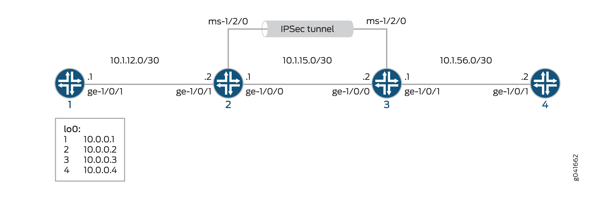
Routers 2 and 3 establish an IPsec tunnel by using a multiservices PIC and manual SA settings. Routers 1 and 4 provide basic connectivity and are used to verify that the IPsec tunnel is operational.
Configuration
This example uses four routers, and involves the following configurations:
Routers 1 and 4 are configured for basic OSPF connectivity with Routers 2 and 3 respectively.
Routers 2 and 3 are configured for OSPF connectivity with Routers 1 and 4 respectively. Routers 2 and 3 are also configured to create an IPsec tunnel by using manual SAs between these two routers. To direct traffic to the IPsec tunnel through the multiservices interface, next-hop style service sets are configured on Routers 2 and 3, and the multiservices interfaces that are configured as the IPsec inside interface are added to the OSPF configuration on the respective routers.
The interface types shown in this example are for indicative
purpose only. For example, you can use so- interfaces instead
of ge- and sp- instead of ms-.
This section contains:
Configuring Router 1
CLI Quick Configuration
To quickly configure this example, copy the following commands, paste them into a text file, remove any line breaks, change any details necessary to match your network configuration, and then copy and paste the commands into the CLI, at the [edit] hierarchy level, of Router 1.
set interfaces ge-1/0/1 description "to R2 ge-1/0/1"
set interfaces ge-1/0/1 unit 0 family inet address 10.1.12.1/30
set interfaces lo0 unit 0 family inet address 10.0.0.1/32
set protocols ospf area 0.0.0.0 interface ge-1/0/1.0
set protocols ospf area 0.0.0.0 interface lo0.0
set routing-options router-id 10.0.0.1
Step-by-Step Procedure
The following example requires you to navigate various levels in the configuration hierarchy. For information about navigating the CLI, see Using the CLI Editor in Configuration Mode in the CLI User Guide.
To configure Router 1 for OSPF connectivity with Router 2:
Configure an Ethernet interface and loopback interface.
[edit interfaces]
user@router1# set ge-1/0/1 description "to R2 ge-1/0/1"
user@router1# set ge-1/0/1 unit 0 family inet address 10.1.12.1/30
user@router1# set lo0 unit 0 family inet address 10.0.0.1/32
Specify the OSPF area and associate the interfaces with the OSPF area.
[edit protocols]
user@router1# set ospf area 0.0.0.0 interface ge-1/0/1.0
user@router1# set ospf area 0.0.0.0 interface lo0.0
Configure the router ID.
[edit routing-options]
user@router1# set router-id 10.0.0.1
Results
From configuration mode, confirm your configuration
by entering the show interfaces, show protocols ospf, and show routing-options commands. If the output does
not display the intended configuration, repeat the instructions in
this example to correct the configuration
user@router1# show interfaces
interfaces {
    ...
    ge-1/0/1 {
        description "to R2 ge-1/0/1";
        unit 0 {
            family inet {
                address 10.1.12.1/30;
            }
        }
    }
    lo0 {
        unit 0 {
            family inet {
                address 10.0.0.1/32;
            }
        }
    }
    ...
}
user@router1# show protocols ospf
ospf {
    area 0.0.0.0 {
        interface ge-1/0/1.0;
        interface lo0.0;
    }
}
user@router1# show routing-options
routing-options  {
    router-id 10.0.0.1;
}
Configuring Router 2
CLI Quick Configuration
To quickly configure this example, copy the following commands, paste them into a text file, remove any line breaks, change any details necessary to match your network configuration, and then copy and paste the commands into the CLI, at the [edit] hierarchy level, of Router 2.
Configuring Interfaces and OSPF Connectivity (with Router 1 and Router 3) on Router 2
set interfaces ge-1/0/0 unit 0 description "to R3 ge-1/0/0"
set interfaces ge-1/0/0 unit 0 family inet address 10.1.15.1/30
set interfaces ge-1/0/1 unit 0 description "to R1 ge-1/0/0"
set interfaces ge-1/0/1 unit 0 family inet address 10.1.12.2/30
set interfaces ms-1/2/0 unit 0 family inet
set interfaces ms-1/2/0 unit 1 family inet
set interfaces ms-1/2/0 unit 1 service-domain inside
set interfaces ms-1/2/0 unit 2 family inet
set interfaces ms-1/2/0 unit 2 service-domain outside
set interfaces lo0 unit 0 family inet address 10.0.0.2/32
set protocols ospf area 0.0.0.0 interface ge-1/0/1.0
set protocols ospf area 0.0.0.0 interface lo0.0
set protocols ospf area 0.0.0.0 interface ms-1/2/0.1
set services ipsec-vpn rule demo-rule-r1-manual-sa term demo-term-manual-sa then remote-gateway 10.1.15.2
set services ipsec-vpn rule demo-rule-r1-manual-sa term demo-term-manual-sa then manual direction bidirectional protocol esp
set services ipsec-vpn rule demo-rule-r1-manual-sa term demo-term-manual-sa then manual direction bidirectional spi 261
set services ipsec-vpn rule demo-rule-r1-manual-sa term demo-term-manual-sa then manual direction bidirectional authentication algorithm hmac-sha1-96
set services ipsec-vpn rule demo-rule-r1-manual-sa term demo-term-manual-sa then manual direction bidirectional authentication key ascii-text demokeyipsecmanualsa
set services ipsec-vpn rule demo-rule-r1-manual-sa term demo-term-manual-sa then manual direction bidirectional encryption algorithm des-cbc
set services ipsec-vpn rule demo-rule-r1-manual-sa term demo-term-manual-sa then manual direction bidirectional encryption key ascii-text manualsa
set services ipsec-vpn rule demo-rule-r1-manual-sa match-direction input
set services service-set demo-ss-manual-sa next-hop-service inside-service-interface ms-1/2/0.1
set services service-set demo-ss-manual-sa next-hop-service outside-service-interface ms-1/2/0.2
set services service-set demo-ss-manual-sa ipsec-vpn-options local-gateway 10.1.15.1
set services service-set demo-ss-manual-sa ipsec-vpn-rules demo-rule-r1-manual-sa
Step-by-Step Procedure
The following example requires you to navigate various levels in the configuration hierarchy. For information about navigating the CLI, see Using the CLI Editor in Configuration Mode in the CLI User Guide.
To configure OSPF connectivity and IPsec tunnel parameters on Router 2:
Configure interface properties. In this step, you configure two Ethernet interfaces (ge-1/0/0 and ge-1/0/1), a loopback interface, and a multiservices interface (ms-1/2/0).
[edit interfaces]
user@router2# set ge-1/0/0 unit 0 description "to R3 ge-1/0/0"
user@router2# set ge-1/0/0 unit 0 family inet address 10.1.15.1/30
user@router2# set ge-1/0/1 unit 0 description "to R1 ge-1/0/0"
user@router2# set ge-1/0/1 unit 0 family inet address 10.1.12.2/30
user@router2# set ms-1/2/0 unit 0 family inet
user@router2# set ms-1/2/0 unit 1 family inet
user@router2# set ms-1/2/0 unit 1 service-domain inside
user@router2# set ms-1/2/0 unit 2 family inet
user@router2# set ms-1/2/0 unit 2 service-domain outside
user@router2# set lo0 unit 0 family inet address 10.0.0.2/32
Specify the OSPF area and associate the interfaces with the OSPF area.
[edit protocols]
user@router2# set ospf area 0.0.0.0 interface ge-1/0/1.0
user@router2# set ospf area 0.0.0.0 interface lo0.0
user@router2# set ospf area 0.0.0.0 interface ms-1/2/0.1
Configure the router ID.
[edit routing-options]
user@router2# set router-ID 10.0.0.2
Configure an IPsec rule. In this step, you configure an IPsec rule and specify manual SA parameters, such as the remote-gateway address, authentication and encryption properties, and so on.
[edit services ipsec-vpn]
user@router2# set rule demo-rule-r1-manual-sa term demo-term-manual-sa then remote-gateway 10.1.15.2
user@router2# set rule demo-rule-r1-manual-sa term demo-term-manual-sa then manual direction bidirectional protocol esp
user@router2# set rule demo-rule-r1-manual-sa term demo-term-manual-sa then manual direction bidirectional spi 261
user@router2# set rule demo-rule-r1-manual-sa term demo-term-manual-sa then manual direction bidirectional authentication algorithm hmac-sha1-96
user@router2# set rule demo-rule-r1-manual-sa term demo-term-manual-sa then manual direction bidirectional authentication key ascii-text demokeyipsecmanualsa
user@router2# set rule demo-rule-r1-manual-sa term demo-term-manual-sa then manual direction bidirectional encryption algorithm des-cbc
user@router2# set rule demo-rule-r1-manual-sa term demo-term-manual-sa then manual direction bidirectional encryption key ascii-text manualsa
user@router2# set rule demo-rule-r1-manual-sa match-direction input
Configure a next-hop style service set, specify the local-gateway address, and associate the IPsec VPN rule with the service set.
[edit services]
user@router2# set service-set demo-ss-manual-sa next-hop-service inside-service-interface ms-1/2/0.1
user@router2# set service-set demo-ss-manual-sa next-hop-service outside-service-interface ms-1/2/0.2
user@router2# set service-set demo-ss-manual-sa ipsec-vpn-options local-gateway 10.1.15.1
user@router2# set service-set demo-ss-manual-sa ipsec-vpn-rules demo-rule-r1-manual-sa
Commit the configuration.
[edit]
user@router2# commit
Results
From configuration mode, confirm your configuration
by entering the show interfaces, show protocols ospf, show routing-options, and show services commands.
If the output does not display the intended configuration, repeat
the instructions in this example to correct the configuration
user@router1# show interfaces
interfaces {
    ...
    ge-1/0/0 {
        unit 0 {
            description "to R3 ge-1/0/0";
            family inet {
                address 10.1.15.1/30;
            }
        }
    }
    ge-1/0/1 {
        unit 0 {
            description "to R1 ge-1/0/1";
            family inet {
                address 10.1.12.2/30;
            }
        }
    }
    ms-1/2/0 {
        unit 0 {
            family inet;
        }
        unit 1 {
            family inet;
            service-domain inside;
        }
        unit 2 {
            family inet;
            service-domain outside;
        }
    }
    lo0 {
        unit 0 {
            family inet {
                address 10.0.0.2/32;
            }
        }
    }
    ...
}
user@router2# show protocols ospf
protocols {
    ospf {
        area 0.0.0.0 {
            interfaces ge-1/0/1.0;
            interface lo0;
            interface ms-1/2/0;
        }
    }
}
user@router2# show routing-options
routing-options {
    router-id 10.0.0.2;
}
user@router2# show services
services  {
    ipsec-vpn {
        rule demo-rule-r1-manual-sa {
            term demo-term-manual-sa {
                then {
                    remote-gateway 10.1.15.2;
                    manual {
                        direction bidirectional {
                            protocol esp;
                            spi 261;
                            authentication {
                                algorithm hmac-sha1-96;
                                key ascii-text "$ABC1223"; ## SECRET-DATA
                            }
                            encryption {
                                algorithm des-cbc;
                                key ascii-text "$ABC123"; ## SECRET-DATA
                            }
                        }
                    }
                }
            }
            match-direction input;
        }
    }
    service-set demo-ss-manual-sa {
        next-hop-service {
            inside-service-interface ms-1/2/0.1;
            outside-service-interface ms-1/2/0.2;
        }
        ipsec-vpn-options {
            local-gateway 10.1.15.1;
        }
        ipsec-vpn-rules demo-rule-r1-manual-sa;
    }
}
Configuring Router 3
CLI Quick Configuration
To quickly configure this example, copy the following commands, paste them into a text file, remove any line breaks, change any details necessary to match your network configuration, and then copy and paste the commands into the CLI, at the [edit] hierarchy level, of Router 3.
set interfaces ge-1/0/1 unit 0 description "to R4 ge-1/0/1"
set interfaces ge-1/0/0 unit 0 family inet address 10.1.56.1/30
set interfaces ge-1/0/0 unit 0 description "to R2 ge-1/0/0"
set interfaces ge-1/0/0 unit 0 family inet address 10.1.15.2/30
set interfaces ms-1/2/0 unit 0 family inet
set interfaces ms-1/2/0 unit 1 family inet
set interfaces ms-1/2/0 unit 1 service-domain inside
set interfaces ms-1/2/0 unit 2 family inet
set interfaces ms-1/2/0 unit 2 service-domain outside
set interfaces lo0 unit 0 family inet address 10.0.0.3/32
set protocols ospf area 0.0.0.0 interface ge-1/0/1.0
set protocols ospf area 0.0.0.0 interface lo0.0
set protocols ospf area 0.0.0.0 interface ms-1/2/0.1
set routing-options router-id 10.0.0.3
set services ipsec-vpn rule demo-rule-r1-manual-sa term demo-term-manual-sa then remote-gateway 10.1.15.1
set services ipsec-vpn rule demo-rule-r1-manual-sa term demo-term-manual-sa then manual direction bidirectional protocol esp
set services ipsec-vpn rule demo-rule-r1-manual-sa term demo-term-manual-sa then manual direction bidirectional spi 261
set services ipsec-vpn rule demo-rule-r1-manual-sa term demo-term-manual-sa then manual direction bidirectional authentication algorithm hmac-sha1-96
set services ipsec-vpn rule demo-rule-r1-manual-sa term demo-term-manual-sa then manual direction bidirectional authentication key ascii-text demokeyipsecmanualsa
set services ipsec-vpn rule demo-rule-r1-manual-sa term demo-term-manual-sa then manual direction bidirectional encryption algorithm des-cbc
set services ipsec-vpn rule demo-rule-r1-manual-sa term demo-term-manual-sa then manual direction bidirectional encryption key ascii-text manualsa
set services ipsec-vpn rule demo-rule-r1-manual-sa match-direction input
set services service-set demo-ss-manual-sa next-hop-service inside-service-interface ms-1/2/0.1
set services service-set demo-ss-manual-sa next-hop-service outside-service-interface ms-1/2/0.2
set services service-set demo-ss-manual-sa ipsec-vpn-options local-gateway 10.1.15.2
set services service-set demo-ss-manual-sa ipsec-vpn-rules demo-rule-r1-manual-sa
Step-by-Step Procedure
The following example requires you to navigate various levels in the configuration hierarchy. For information about navigating the CLI, see Using the CLI Editor in Configuration Mode in the CLI User Guide.
To configure OSPF connectivity and IPsec tunnel parameters on Router 3:
Configure interface properties. In this step, you configure two Ethernet interfaces (ge-1/0/0 and ge-1/0/1), a loopback interface, and a multiservices interface (ms-1/2/0).
[edit interfaces]
user@router3# set ge-1/0/0 unit 0 description "to R4 ge-1/0/0"
user@router3# set ge-1/0/0 unit 0 family inet address 10.1.56.1/30
user@router3# set ge-1/0/1 unit 0 description "to R2 ge-1/0/1"
user@router3# set ge-1/0/1 unit 0 family inet address 10.1.15.2/30
user@router3# set ms-1/2/0 unit 0 family inet
user@router3# set ms-1/2/0 unit 1 family inet
user@router3# set ms-1/2/0 unit 1 service-domain inside
user@router3# set ms-1/2/0 unit 2 family inet
user@router3# set ms-1/2/0 unit 2 service-domain outside
user@router3# set lo0 unit 0 family inet address 10.0.0.3/32
Specify the OSPF area and associate the interfaces with the OSPF area.
[edit protocols]
user@router3# set ospf area 0.0.0.0 interface ge-1/0/1.0
user@router3# set ospf area 0.0.0.0 interface lo0.0
user@router3# set ospf area 0.0.0.0 interface ms-1/2/0.1
Configure a router ID.
[edit routing-options]
user@router3# set router-id 10.0.0.3
Configure an IPsec rule. In this step, you configure an IPsec rule and specify manual SA parameters, such as the remote-gateway address, authentication and encryption properties, and so on.
[edit services ipsec-vpn]
user@router3# set rule demo-rule-r1-manual-sa term demo-term-manual-sa then remote-gateway 10.1.15.1
user@router3# set rule demo-rule-r1-manual-sa term demo-term-manual-sa then manual direction bidirectional protocol esp
user@router3# set rule demo-rule-r1-manual-sa term demo-term-manual-sa then manual direction bidirectional spi 261
user@router3# set rule demo-rule-r1-manual-sa term demo-term-manual-sa then manual direction bidirectional authentication algorithm hmac-sha1-96
user@router3# set rule demo-rule-r1-manual-sa term demo-term-manual-sa then manual direction bidirectional authentication key ascii-text demokeyipsecmanualsa
user@router3# set rule demo-rule-r1-manual-sa term demo-term-manual-sa then manual direction bidirectional encryption algorithm des-cbc
user@router3# set rule demo-rule-r1-manual-sa term demo-term-manual-sa then manual direction bidirectional encryption key ascii-text manualsa
user@router3# set rule demo-rule-r1-manual-sa match-direction input
Configure a next-hop style service set, specify the local-gateway address, and associate the IPsec VPN rule with the service set.
[edit services]
user@router3# set service-set demo-ss-manual-sa next-hop-service inside-service-interface ms-1/2/0.1
user@router3# set service-set demo-ss-manual-sa next-hop-service outside-service-interface ms-1/2/0.2
user@router3# set service-set demo-ss-manual-sa ipsec-vpn-options local-gateway 10.1.15.2
user@router3# set service-set demo-ss-manual-sa ipsec-vpn-rules demo-rule-r1-manual-sa
Commit the configuration.
[edit]
user@router3# commit
Results
From configuration mode, confirm your configuration
by entering the show interfaces, show protocols ospf, show routing-options, and show services commands.
If the output does not display the intended configuration, repeat
the instructions in this example to correct the configuration
user@router3# show interfaces
interfaces {
    ge-1/0/1 {
        unit 0 {
            description "to R4 ge-1/0/1";
            family inet {
                address 10.1.56.1/30;
            }
        }
    }
    ge-1/0/0 {
        unit 0 {
            description "to R2 ge-1/0/0";
            family inet {
                address 10.1.15.2/30;
            }
        }
    }
    ms-1/2/0 {
        unit 0 {
            family inet;
        }
        unit 1 {
            family inet;
            service-domain inside;
        }
        unit 2 {
            family inet;
            service-domain outside;
        }
    }
    lo0 {
        unit 0 {
            family inet {
                address 10.0.0.3/32;
            }
        }
    }
}
user@router3# show protocols ospf
protocols {
    ospf {
        area 0.0.0.0 {
            interface ge-1/0/1.0;
            interface lo0.0;
            interface ms-1/2/0.1;
        }
    }
}
user@router3# show routing-options
routing-options {
    router-id 10.0.0.3;
}
user@router3# show services
services {
    ipsec-vpn {
        rule demo-rule-r1-manual-sa {
            term demo-term-manual-sa {
                then {
                    remote-gateway 10.1.15.1;
                    manual {
                        direction bidirectional {
                            protocol esp;
                            spi 261;
                            authentication {
                                algorithm hmac-sha1-96;
                                key ascii-text "$ABC123"; ## SECRET-DATA
                            }
                            encryption {
                                algorithm des-cbc;
                                key ascii-text "$ABC123"; ## SECRET-DATA
                            }
                        }
                    }
                }
            }
            match-direction input;
        }
    }
    service-set demo-ss-manual-sa {
        next-hop-service {
            inside-service-interface ms-1/2/0.1;
            outside-service-interface ms-1/2/0.2;
        }
        ipsec-vpn-options {
            local-gateway 10.1.15.2;
        }
        ipsec-vpn-rules demo-rule-r1-manual-sa;
    }
}
Configuring Router 4
CLI Quick Configuration
To quickly configure this example, copy the following commands, paste them into a text file, remove any line breaks, change any details necessary to match your network configuration, and then copy and paste the commands into the CLI, at the [edit] hierarchy level, of Router 4.
set interfaces ge-1/0/1 description "to R3 ge-1/0/1"
set interfaces ge-1/0/1 unit 0 family inet address 10.1.56.2/30
set interfaces lo0 unit 0 family inet address 10.0.0.4/32
set protocols ospf area 0.0.0.0 interface ge-1/0/1.0
set protocols ospf area 0.0.0.0 interface lo0.0
set routing-options router-id 10.0.0.4
Step-by-Step Procedure
The following example requires you to navigate various levels in the configuration hierarchy. For information about navigating the CLI, see Using the CLI Editor in Configuration Mode in the CLI User Guide.
To set up OSPF connectivity with Router 3
Configure the interfaces. In this step, you configure an Ethernet interface (ge-1/0/1) and a loopback interface.
user@router4# set interfaces ge-1/0/1 description "to R3 ge-1/0/1"
user@router4# set interfaces ge-1/0/1 unit 0 family inet address 10.1.56.2/30
user@router4# set interfaces lo0 unit 0 family inet address 10.0.0.4/32
Specify the OSPF area and associate the interfaces with the OSPF area.
user@router4# set protocols ospf area 0.0.0.0 interface ge-1/0/1.0
user@router4# set protocols ospf area 0.0.0.0 interface lo0.0
Configure the router ID.
[edit routing-options]
user@router4# set router-id 10.0.0.4
Commit the configuration.
[edit]
user@router4# commit
Results
From configuration mode, confirm your configuration
by entering the show interfaces, show protocols ospf, and show routing-options commands. If the output does
not display the intended configuration, repeat the instructions in
this example to correct the configuration
user@router4# show interfaces
interfaces {
    ge-1/0/1 {
        description "to R3 ge-1/0/1";
        unit 0 {
            family inet {
                address 10.1.56.2/30;
            }
        }
    }
    lo0{
        unit 0 {
            family inet {
                address 10.0.0.4/32;
            }
        }
    }
}
user@router4# show routing-options
routing-options {
    router-id 10.0.0.4;
}
user@router4# show protocols ospf
protocols {
    ospf {
        area 0.0.0.0 {
            interface lo0.0;
            interface ge-1/0/1.0;
        }
    }
}
Verification
To confirm that the manual SA configuration is working properly, perform the following tasks:
- Verifying Traffic Flow Through the IPsec Tunnel
- Verifying the Security Associations on Router 2
- Verifying the Security Associations on Router 3
Verifying Traffic Flow Through the IPsec Tunnel
Purpose
Verify that the IPsec tunnel carries traffic between Router 1 and Router 4.
Action
Issue a ping command from Router 1 to lo0 on Router 4.
user@router1> ping 10.0.0.4
PING 10.0.0.4 (10.0.0.4): 56 data bytes
64 bytes from 10.0.0.4: icmp_seq=0 ttl=254 time=1.375 ms
64 bytes from 10.0.0.4: icmp_seq=1 ttl=254 time=18.375 ms
64 bytes from 10.0.0.4: icmp_seq=2 ttl=254 time=1.120 ms
^C
--- 10.0.0.4 ping statistics ---
3 packets transmitted, 3 packets received, 0% packet loss
round-trip min/avg/max/stddev = 1.120/6.957/18.375/8.075 ms
Meaning
The output shows that Router 1 is able to reach Router 4 over the IPsec tunnel.
Verifying the Security Associations on Router 2
Purpose
Verify that the security associations are active on Router 2 and that the traffic is flowing over the IPsec tunnel.
Action
To verify that the security associations are active, Issue
show services ipsec-vpn ipsec security-associations detailon Router 2.user@router2> show services ipsec-vpn ipsec security-associations detail Service set: demo-ss-manual-sa Rule: demo-rule-r1-manual-sa, Term: demo-term-manual-sa, Tunnel index: 1 Local gateway: 10.1.15.1, Remote gateway: 10.1.15.2 Local identity: ipv4_subnet(any:0,[0..7]=10.0.0.0/8) Remote identity: ipv4_subnet(any:0,[0..7]=0.0.0.0/0) Direction: inbound, SPI: 261, AUX-SPI: 0 Mode: tunnel, Type: manual, State: Installed Protocol: ESP, Authentication: hmac-sha1-96, Encryption: des-cbc Anti-replay service: Disabled Direction: outbound, SPI: 261, AUX-SPI: 0 Mode: tunnel, Type: manual, State: Installed Protocol: ESP, Authentication: hmac-sha1-96, Encryption: des-cbc Anti-replay service: Disabled
To verify that traffic is traveling over the bidirectional IPsec tunnel, issue
show services ipsec-vpn ipsec statisticson Router 2.user@router2> show services ipsec-vpn ipsec statistics PIC: ms-1/2/0, Service set: demo-ss-manual-sa sESP Statistics: Encrypted bytes: 1616 Decrypted bytes: 1560 Encrypted packets: 20 Decrypted packets: 19 AH Statistics: Input bytes: 0 Output bytes: 0 Input packets: 0 Output packets: 0 Errors: AH authentication failures: 0, Replay errors: 0 ESP authentication failures: 0, ESP decryption failures: 0 Bad headers: 0, Bad trailers: 0
Meaning
The show services ipsec-vpn ipsec security-associations
detail command output shows the SA properties that you configured.
The show services ipsec-vpn ipsec statistics command
output shows the traffic flow over the IPsec tunnel.
Verifying the Security Associations on Router 3
Purpose
Verify the security associations and flow of traffic over the IPsec tunnel.
Action
To verify that the security associations are active, Issue
show services ipsec-vpn ipsec security-associations detailon Router 3.user@router3> show services ipsec-vpn ipsec security-associations detail Service set: demo-ss-manual-sa Rule: demo-rule-r1-manual-sa, Term: demo-term-manual-sa, Tunnel index: 1 Local gateway: 10.1.15.2, Remote gateway: 10.1.15.1 Local identity: ipv4_subnet(any:0,[0..7]=10.0.0.0/8) Remote identity: ipv4_subnet(any:0,[0..7]=0.0.0.0/0) Direction: inbound, SPI: 261, AUX-SPI: 0 Mode: tunnel, Type: manual, State: Installed Protocol: ESP, Authentication: hmac-sha1-96, Encryption: des-cbc Anti-replay service: Disabled Direction: outbound, SPI: 261, AUX-SPI: 0 Mode: tunnel, Type: manual, State: Installed Protocol: ESP, Authentication: hmac-sha1-96, Encryption: des-cbc Anti-replay service: Disabled
To verify that traffic is traveling over the bidirectional IPsec tunnel, issue
show services ipsec-vpn ipsec statisticson Router 3.user@router3> show services ipsec-vpn ipsec statistics PIC: ms-1/2/0, Service set: demo-ss-manual-sa ESP Statistics: Encrypted bytes: 1560 Decrypted bytes: 1616 Encrypted packets: 19 Decrypted packets: 20 AH Statistics: Input bytes: 0 Output bytes: 0 Input packets: 0 Output packets: 0 Errors: AH authentication failures: 0, Replay errors: 0 ESP authentication failures: 0, ESP decryption failures: 0 Bad headers: 0, Bad trailers: 0
Meaning
The show services ipsec-vpn ipsec security-associations
detail command output shows the SA properties that you configured.
The show services ipsec-vpn ipsec statistics command
output shows the traffic flow over the IPsec tunnel.