IPsec Rules and Rulesets
Example: Configuring IKE Dynamic SAs
This example shows how to configure IKE dynamic SAs and contains the following sections.
Requirements
This example uses the following hardware and software components:
Four M Series, MX Series, or T Series routers with multiservices interfaces installed in them.
Junos OS Release 9.4 or later.
No special configuration beyond device initiation is required before you can configure this feature.
Overview and Topology
A security association (SA) is a simplex connection that enables two hosts to securely communicate with each other by means of IPsec.
Dynamic SAs are best suited for large-scale, geographically distributed networks where manual distribution, maintenance, and tracking of keys are difficult tasks. Dynamic SAs are configured with a set of proposals that are negotiated by the security gateways. The keys are generated as part of the negotiation and do not need to be specified in the configuration. A dynamic SA includes one or more proposals that allow you to prioritize a list of protocols and algorithms to be negotiated with the peer.
Topology
Figure 1 shows an IPsec topology that contains a group of four routers. This configuration requires Routers 2 and 3 to establish an IPsec tunnel by using an IKE dynamic SA, enhanced authentication, and encryption. Routers 1 and 4 provide basic connectivity and are used to verify that the IPsec tunnel is operational.
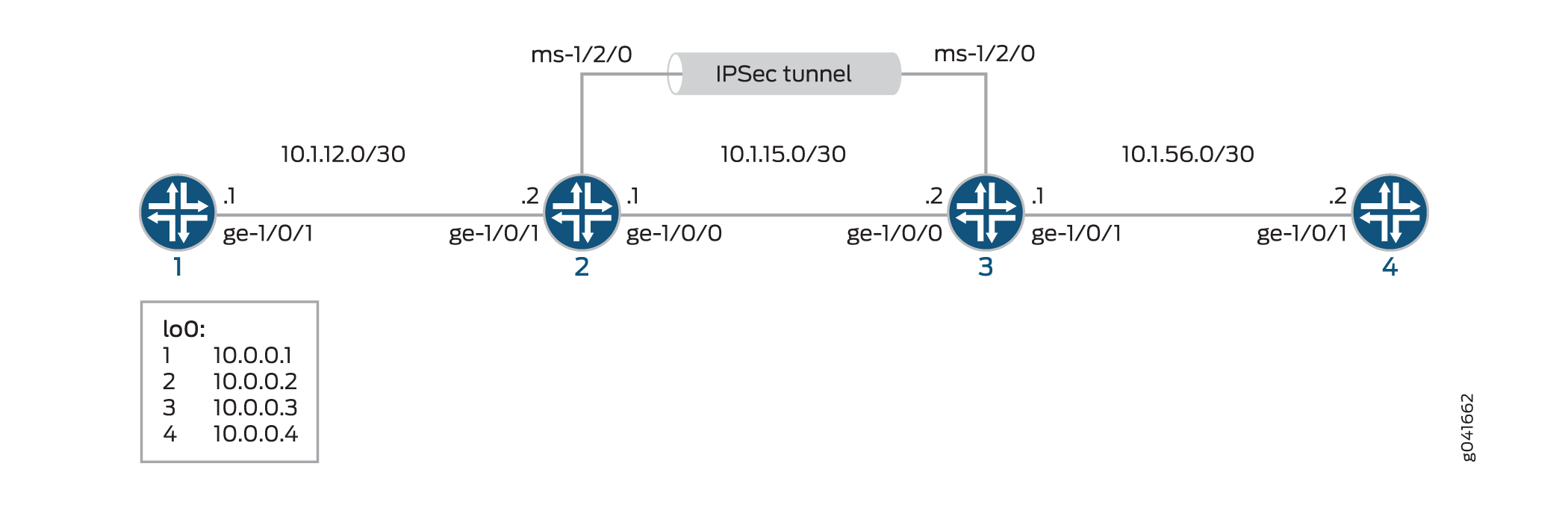
When you do not specify an IKE proposal, an IPsec proposal, and an IPsec policy on a MultiServices PIC, the Junos OS defaults to the highest level of encryption and authentication. As a result, the default authentication protocol is ESP, the default authentication mode is HMAC-SHA1-96, and the default encryption mode is 3DES-CBC.
Configuration
To configure IKE dynamic SA, perform these tasks:
The interface types shown in this example are for indicative
purpose only. For example, you can use so- interfaces instead
of ge- and sp- instead of ms-.
Configuring Router 1
CLI Quick Configuration
To quickly configure this example, copy the following commands, paste them into a text file, remove any line breaks, change any details necessary to match your network configuration, and then copy and paste the commands into the CLI, at the [edit] hierarchy level, of Router 1.
set interfaces ge-0/0/0 description "to R2 ge-0/0/0"
set interfaces ge-0/0/0 unit 0 family inet address 10.1.12.2/30
set interfaces lo0 unit 0 family inet address 10.0.0.1/32
set routing-options router-id 10.0.0.1
set protocols ospf area 0.0.0.0 interface ge-0/0/0
set protocols ospf area 0.0.0.0 interface lo0.0
Step-by-Step Procedure
The following example requires you to navigate various levels in the configuration hierarchy. For information about navigating the CLI, see Using the CLI Editor in Configuration Mode in the CLI User Guide.
To configure Router 1 for OSPF connectivity with Router 2:
Configure an Ethernet interface and a loopback interface.
[edit interfaces]
user@router1# set ge-0/0/0 description "to R2 ge-0/0/0"
user@router1# set ge-0/0/0 unit 0 family inet address 10.1.12.2/30
user@router1# set lo0 unit 0 family inet address 10.0.0.1/32
Specify the OSPF area and associate the interfaces with the OSPF area.
[edit interfaces]
user@router1# set ospf area 0.0.0.0 interface ge-0/0/0.0
user@router1# set ospf area 0.0.0.0 interface lo0.0
Configure the router ID.
[edit routing-options]
user@router1# set router-id 10.0.0.1
Commit the configuration.
[edit]
user@router1# commit
Results
From configuration mode, confirm your configuration
by entering the show interfaces, show protocols ospf, and show routing-options commands. If the output does
not display the intended configuration, repeat the instructions in
this example to correct the configuration
user@router1# show interfaces
interfaces {
    ge-0/0/0 {
        description "To R2 ge-0/0/0";
        unit 0 {
            family inet {
                address 10.1.12.2/30;
            }
        }
    }
    lo0 {
        unit 0 {
            family inet {
                address 10.0.0.1/32;
            }
        }
    }
}
user@router1# show protocols ospf
protocols {
    ospf {
        area 0.0.0.0 {
            interface ge-0/0/0.0;
            interface lo0.0;
        }
    }
}
user@router1# show routing-options
routing-options  {
    router-id 10.0.0.1;
}
Configuring Router 2
CLI Quick Configuration
To quickly configure this example, copy the following commands, paste them into a text file, remove any line breaks, change any details necessary to match your network configuration, and then copy and paste the commands into the CLI, at the [edit] hierarchy level, of Router 2.
set interfaces ge-0/0/0 description "to R1 ge-0/0/0"
set interfaces ge-0/0/0 unit 0 family inet address 10.1.12.1/30
set interfaces ge-0/0/1 description "to R3 ge-0/0/1"
set interfaces ge-0/0/1 unit 0 family inet address 10.1.15.1/30
set interfaces ms-1/2/0 services-options syslog host local services info
set interfaces ms-1/2/0 unit 0 family inet
set interfaces ms-1/2/0 unit 1 family inet
set interfaces ms-1/2/0 unit 1 service-domain inside
set interfaces ms-1/2/0 unit 2 family inet
set interfaces ms-1/2/0 unit 2 service-domain outside
set interfaces lo0 unit 0 family inet address 10.0.0.2/32
set protocols ospf area 0.0.0.0 interface ge-0/0/0.0
set protocols ospf area 0.0.0.0 interface lo0.0
set protocols ospf area 0.0.0.0 interface ms-1/2/0.1
set routing-options router-id 10.0.0.2
set services ipsec-vpn rule rule-ike term term-ike then remote-gateway 10.1.15.2
set services ipsec-vpn rule rule-ike term term-ike then dynamic ike-policy ike-demo-policy
set services ipsec-vpn rule rule-ike term term-ike then dynamic ipsec-policy ipsec-demo-policy
set services ipsec-vpn rule match-direction input
set services ipsec-vpn ike proposal ike-demo-proposal authentication-method pre-shared-keys
set services ipsec-vpn ike proposal ike-demo-proposal dh-group group2
set services ipsec-vpn ike policy ike-demo-policy pre-shared proposals demo-proposal
set services ipsec-vpn ike policy ike-demo-policy pre-shared pre-shared-key ascii-text keyfordemo
set services ipsec-vpn ipsec proposal ipsec-demo-proposal protocol esp
set services ipsec-vpn ipsec proposal ipsec-demo-proposal authentication-algorithm hmac-sha1-96
set services ipsec-vpn ipsec proposal ipsec-demo-proposal encryption-algorithm 3des-cbc
set services ipsec-vpn ipsec policy ipsec-demo-policy perfect-forward-secrecy keys group2
set services ipsec-vpn ipsec proposals ipsec-demo-proposal
set services service-set demo-service-set next-hop-service inside-service-interface ms-1/2/0.1
set services service-set demo-service-set next-hop-service outside-service-interface ms-1/2/0.2
set services service-set demo-service-set ipsec-vpn-options local-gateway 10.1.15.1
set services service-set demo-service-set ipsec-vpn-rules rule-ike
Step-by-Step Procedure
The following example requires you to navigate various levels in the configuration hierarchy. For information about navigating the CLI, see Using the CLI Editor in Configuration Mode in the CLI User Guide.
To configure OSPF connectivity and IPsec tunnel parameters on Router 2:
Configure interface properties. In this step, you configure two Ethernet interfaces (ge-1/0/0 and ge-1/0/1), a loopback interface, and a multiservices interface (ms-1/2/0).
[edit interfaces]
user@router2# set ge-0/0/0 description "to R1 ge-0/0/0"
user@router2# set ge-0/0/0 unit 0 family inet address 10.1.12.1/30
user@router2# set ge-0/0/1 description "to R3 ge-0/0/1"
user@router2# set ge-0/0/1 unit 0 family inet address 10.1.15.1/30
user@router2# set ms-1/2/0 services-options syslog host local services info
user@router2# set ms-1/2/0 unit 0 family inet
user@router2# set ms-1/2/0 unit 1 family inet
user@router2# set ms-1/2/0 unit 1 service-domain inside
user@router2# set ms-1/2/0 unit 2 family inet
user@router2# set ms-1/2/0 unit 2 service-domain outside
user@router2# set lo0 unit 0 family inet address 10.0.0.2/32
Specify the OSPF area and associate the interfaces with the OSPF area.
[edit protocols]
user@router2# set ospf area 0.0.0.0 interface ge-0/0/0.0
user@router2# set ospf area 0.0.0.0 interface lo0.0
user@router2# set ospf area 0.0.0.0 interface ms-1/2/0.1
Configure the router ID.
[edit routing-options]
user@router2# set router-ID 10.0.0.2
Configure an IPsec rule. In this step, you configure an IPsec rule, specify manual SA parameters, such as the remote gateway address, authentication and encryption properties, and so on.
Note:By default, Junos OS uses IKE policy version 1.0. Junos OS Release 11.4 and later also support IKE policy version 2.0 which you must configure at
[edit services ipsec-vpn ike policy policy-name pre-shared].[edit services ipsec-vpn] user@router2# set rule rule-ike term term-ike then remote-gateway 10.1.15.2 user@router2# set rule rule-ike term term-ike then dynamic ike-policy ike-demo-policy user@router2# set rule rule-ike term term-ike then dynamic ipsec-policy ipsec-demo-policy user@router2# set rule match-direction input user@router2# set ike proposal ike-demo-proposal authentication-method pre-shared-keys user@router2# set ike proposal ike-demo-proposal dh-group group2 user@router2# set ike policy ike-demo-policy pre-shared proposals demo-proposal user@router2# set ike policy ike-demo-policy pre-shared pre-shared-key ascii-text keyfordemo user@router2# set ipsec proposal ipsec-demo-proposal protocol esp user@router2# set ipsec proposal ipsec-demo-proposal authentication-algorithm hmac-sha1-96 user@router2# set ipsec proposal ipsec-demo-proposal encryption-algorithm 3des-cbc user@router2# set ipsec policy ipsec-demo-policy perfect-forward-secrecy keys group2 user@router2# set ipsec proposals ipsec-demo-proposal
Configure a next-hop style service set, specify the local-gateway address, and associate the IPsec VPN rule with the service set.
[edit services]
user@router2# set service-set demo-service-set next-hop-service inside-service-interface ms-1/2/0.1
user@router2# set service-set demo-service-set next-hop-service outside-service-interface ms-1/2/0.2
user@router2# set service-set demo-service-set ipsec-vpn-options local-gateway 10.1.15.1
user@router2# set service-set demo-service-set ipsec-vpn-rules rule-ike
Commit the configuration.
[edit]
user@router2# commit
Results
From configuration mode, confirm your configuration
by entering the show interfaces, show protocols ospf, show routing-options, and show services commands.
If the output does not display the intended configuration, repeat
the instructions in this example to correct the configuration
user@router1# show interfaces
interfaces {
    ge-0/0/0 {
        description "To R1 ge-0/0/0";
        unit 0 {
            family inet {
                address 10.1.12.1/30;
            }
        }
    }

    ge-0/0/1 {
        description "To R3 ge-0/0/1";
        unit 0 {
            family inet {
                address 10.1.15.1/30;
            }
        }
    }

    ms-1/2/0 {
        services-options {
            syslog {
                host local {
                    services info;
                }
            }
        }
        unit 0 {
            family inet;
        }
        unit 1 {
            family inet;
            service-domain inside;
        }
        unit 2 {
            family inet;
            service-domain outside;
        }
    }
    lo0 {
        unit 0 {
            family inet {
                address 10.0.0.2/32;
            }
        }
    }
}
user@router2# show protocols ospf
protocols {
    ospf {
        area 0.0.0.0 {
            interface ge-0/0/0.0;
            interface lo0.0;
            interface ms-1/2/0.1;
        }
    }
}
user@router2# show routing-options
routing-options {
    router-id 10.0.0.2;
}
user@router2# show services
services {
    ipsec-vpn {
        rule rule-ike {
            term term-ike {
                then {
                    remote-gateway 10.1.15.2;
                    dynamic {
                        ike-policy ike-demo-policy;
                        ipsec-policy ipsec-demo-policy;
                    }
                }
            }
            match-direction input;
        }
        ike {
            proposal ike-demo-proposal {
                authentication-method pre-shared-keys;
                dh-group group2;
            }
            policy ike-demo-policy {
                proposals demo-proposal;
                pre-shared-key ascii-text "$ABC123"; ## SECRET-DATA
            }
        }
        ipsec {
        proposal ipsec-demo-proposal {
            protocol esp;
            authentication-algorithm hmac-sha1-96;
            encryption-algorithm 3des-cbc;
        }
        policy ipsec-demo-policy {
            perfect-forward-secrecy {
                keys group2;
            }
            proposals ipsec-demo-proposal;
        }
    }
}
service-set demo-service-set {
    next-hop-service {
        inside-service-interface ms-1/2/0.1;
        outside-service-interface ms-1/2/0.2;
    }
    ipsec-vpn-options {
        local-gateway 10.1.15.1;
    }
    ipsec-vpn-rules rule-ike;
}
service-set demo-service-set {
    next-hop-service {
        inside-service-interface ms-1/2/0.1;
        outside-service-interface ms-1/2/0.2;
    }
    ipsec-vpn-options {
        local-gateway 10.1.15.2;
    }
    ipsec-vpn-rules rule-ike;
}
Configuring Router 3
CLI Quick Configuration
To quickly configure this example, copy the following commands, paste them into a text file, remove any line breaks, change any details necessary to match your network configuration, and then copy and paste the commands into the CLI, at the [edit] hierarchy level, of Router 3.
set interfaces ge-0/0/0 description "to R4 ge-0/0/0"
set interfaces ge-0/0/0 unit 0 family inet address 10.1.56.1/30
set interfaces ge-0/0/1 description "to R2 ge-0/0/1"
set interfaces ge-0/0/1 unit 0 family inet address 10.1.15.2/30
set interfaces ms-1/2/0 services-options syslog host local services info
set interfaces ms-1/2/0 unit 0 family inet
set interfaces ms-1/2/0 unit 1 family inet
set interfaces ms-1/2/0 unit 1 service-domain inside
set interfaces ms-1/2/0 unit 2 family inet
set interfaces ms-1/2/0 unit 2 service-domain outside
set interfaces lo0 unit 0 family inet address 10.0.0.3/32
set protocols ospf area 0.0.0.0 interface ge-0/0/0.0
set protocols ospf area 0.0.0.0 interface lo0.0
set protocols ospf area 0.0.0.0 interface ms-1/2/0.1
set routing-options router-id 10.0.0.3
set services ipsec-vpn rule rule-ike term term-ike then remote-gateway 10.1.15.1
set services ipsec-vpn rule rule-ike term term-ike then dynamic ike-policy ike-demo-policy
set services ipsec-vpn rule rule-ike term term-ike then dynamic ipsec-policy ipsec-demo-policy
set services ipsec-vpn rule match-direction input
set services ipsec-vpn ike proposal ike-demo-proposal authentication-method pre-shared-keys
set services ipsec-vpn ike proposal ike-demo-proposal dh-group group2
set services ipsec-vpn ike policy ike-demo-policy pre-shared proposals demo-proposal
set services ipsec-vpn ike policy ike-demo-policy pre-shared pre-shared-key ascii-text keyfordemo
set services ipsec-vpn ipsec proposal ipsec-demo-proposal protocol esp
set services ipsec-vpn ipsec proposal ipsec-demo-proposal authentication-algorithm hmac-sha1-96
set services ipsec-vpn ipsec proposal ipsec-demo-proposal encryption-algorithm 3des-cbc
set services ipsec-vpn ipsec policy ipsec-demo-policy perfect-forward-secrecy keys group2
set services ipsec-vpn ipsec proposals ipsec-demo-proposal
set services service-set demo-service-set next-hop-service inside-service-interface ms-1/2/0.1
set services service-set demo-service-set next-hop-service outside-service-interface ms-1/2/0.2
set services service-set demo-service-set ipsec-vpn-options local-gateway 10.1.15.2
set services service-set demo-service-set ipsec-vpn-rules rule-ike
Step-by-Step Procedure
The following example requires you to navigate various levels in the configuration hierarchy. For information about navigating the CLI, see Using the CLI Editor in Configuration Mode in the CLI User Guide.
To configure OSPF connectivity and IPsec tunnel parameters on Router 3:
Configure interface properties. In this step, you configure two Ethernet interfaces (ge-1/0/0 and ge-1/0/1), a loopback interface, and a multiservices interface (ms-1/2/0).
[edit interfaces]
user@router3# set ge-0/0/0 description "to R4 ge-0/0/0"
user@router3# set ge-0/0/0 unit 0 family inet address 10.1.56.1/30
user@router3# set ge-0/0/1 description "to R2 ge-0/0/1"
user@router3# set ge-0/0/1 unit 0 family inet address 10.1.15.2/30
user@router3# set ms-1/2/0 services-options syslog host local services info
user@router3# set ms-1/2/0 unit 0 family inet
user@router3# set ms-1/2/0 unit 1 family inet
user@router3# set ms-1/2/0 unit 1 service-domain inside
user@router3# set ms-1/2/0 unit 2 family inet
user@router3# set ms-1/2/0 unit 2 service-domain outside
user@router3# set lo0 unit 0 family inet address 10.0.0.3/32
Specify the OSPF area and associate the interfaces with the OSPF area.
[edit protocols]
user@router3# set ospf area 0.0.0.0 interface ge-0/0/0.0
user@router3# set ospf area 0.0.0.0 interface lo0.0
user@router3# set ospf area 0.0.0.0 interface ms-1/2/0.1
Configure a router ID.
[edit routing-options]
user@router3# set router-id 10.0.0.3
Configure an IPsec rule. In this step, you configure an IPsec rule and specify manual SA parameters, such as the remote gateway address, authentication and encryption properties, and so on.
[edit services ipsec-vpn]
user@router3# set rule rule-ike term term-ike then remote-gateway 10.1.15.1
user@router3# set rule rule-ike term term-ike then dynamic ike-policy ike-demo-policy
user@router3# set rule rule-ike term term-ike then dynamic ipsec-policy ipsec-demo-policy
user@router3# set rule match-direction input
user@router3#  set ike proposal ike-demo-proposal authentication-method pre-shared-keys
user@router3# set ike proposal ike-demo-proposal dh-group group2
user@router3# set ike policy ike-demo-policy pre-shared proposals demo-proposal
user@router3# set ike policy ike-demo-policy pre-shared pre-shared-key ascii-text keyfordemo
user@router3# set ipsec proposal ipsec-demo-proposal protocol esp
user@router3# set ipsec proposal ipsec-demo-proposal authentication-algorithm hmac-sha1-96
user@router3# set ipsec proposal ipsec-demo-proposal encryption-algorithm 3des-cbc
user@router3# set ipsec policy ipsec-demo-policy perfect-forward-secrecy keys group2
user@router3# set ipsec proposals ipsec-demo-proposal
Configure a next-hop style service set, specify the local-gateway address, and associate the IPsec VPN rule with the service set.
[edit services]
user@router3# set service-set demo-service-set next-hop-service inside-service-interface ms-1/2/0.1
user@router3# set service-set demo-service-set next-hop-service outside-service-interface ms-1/2/0.2
user@router3# set service-set demo-service-set ipsec-vpn-options local-gateway 10.1.15.2
user@router3# set service-set demo-service-set ipsec-vpn-rules rule-ike
Commit the configuration.
[edit]
user@router3# commit
Results
From configuration mode, confirm your configuration
by entering the show interfaces, show protocols ospf, show routing-options, and show services commands.
If the output does not display the intended configuration, repeat
the instructions in this example to correct the configuration
user@router3# show interfaces
interfaces {
    ge-0/0/0 {
        description "To R4 ge-0/0/0";
        unit 0 {
            family inet {
                address 10.1.56.1/30;
            }
        }
    }
    ge-0/0/1 {
        description "To R2 ge-0/0/1";
        unit 0 {
            family inet {
                address 10.1.15.2/30;
            }
        }
    }
    ms-1/2/0 {
        services-options {
            syslog {
                host local {
                    services info;
                }
            }
        }
        unit 0 {
            family inet {
            }
            unit 1 {
                family inet;
                service-domain inside;
            }
            unit 2 {
                family inet;
                service-domain outside;
            }
        }
        lo0 {
            unit 0 {
                family inet {
                    address 10.0.0.3/32;
                }
            }
        }
    }
}
user@router3# show protocols ospf
protocols {
    ospf {
        area 0.0.0.0 {
            interface ge-0/0/0.0;
            interface lo0.0;
            interface ms-1/2/0.1;
        }
    }
}
user@router3# show routing-options
routing-options {
    router-id 10.0.0.3;
}
user@router3# show services
services {
    ipsec-vpn {
        rule rule-ike {
            term term-ike {
                then {
                    remote-gateway 10.1.15.1;
                    dynamic {
                        ike-policy ike-demo-policy;
                        ipsec-policy ipsec-demo-policy;
                    }
                }
            }
            match-direction input;
        }
        ike {
            proposal ike-demo-proposal {
                authentication-method pre-shared-keys;
                dh-group group2;
            }
            policy ike-demo-policy {
                proposals demo-proposal;
                pre-shared-key ascii-text "$ABC123"; ## SECRET-DATA
            }
        }
        ipsec {
        proposal ipsec-demo-proposal {
            protocol esp;
            authentication-algorithm hmac-sha1-96;
            encryption-algorithm 3des-cbc;
        }
        policy ipsec-demo-policy {
            perfect-forward-secrecy {
                keys group2;
            }
            proposals ipsec-demo-proposal;
        }
    }
}
Configuring Router 4
CLI Quick Configuration
To quickly configure this example, copy the following commands, paste them into a text file, remove any line breaks, change any details necessary to match your network configuration, and then copy and paste the commands into the CLI, at the [edit] hierarchy level, of Router 4.
set interfaces ge-0/0/0 description "to R3 ge-0/0/0"
set interfaces ge-0/0/0 unit 0 family inet address 10.1.56.2/30
set interfaces lo0 unit 0 family inet address 10.0.0.4/32
set protocols ospf area 0.0.0.0 interface ge-0/0/0.0
set protocols ospf area 0.0.0.0 interface lo0.0
set routing-options router-id 10.0.0.4
Step-by-Step Procedure
The following example requires you to navigate various levels in the configuration hierarchy. For information about navigating the CLI, see Using the CLI Editor in Configuration Mode in the CLI User Guide.
To set up OSPF connectivity with Router 4
Configure the interfaces. In this step, you configure an Ethernet interface (ge-1/0/1) and a loopback interface.
user@router4# set interfaces ge-0/0/0 description "to R3 ge-0/0/0"
user@router4# set interfaces ge-0/0/0 unit 0 family inet address 10.1.56.2/30
user@router4# set interfaces lo0 unit 0 family inet address 10.0.0.4/32
Specify the OSPF area and associate the interfaces with the OSPF area.
user@router4# set protocols ospf area 0.0.0.0 interface ge-0/0/0
user@router4# set protocols ospf area 0.0.0.0 interface lo0.0
Configure the router ID.
[edit routing-options]
user@router4# set router-id 10.0.0.4
Results
From configuration mode, confirm your configuration
by entering the show interfaces, show protocols ospf, and show routing-options commands. If the output does
not display the intended configuration, repeat the instructions in
this example to correct the configuration
user@router4# show interfaces
interfaces {
    ge-0/0/0 {
        description "To R3 ge-0/0/0";
        unit 0 {
            family inet {
                address 10.1.56.2/30;
            }
        }
    }
    lo0 {
        unit 0 {
            family inet {
                address 10.0.0.4/32;
            }
        }
    }
}
user@router4# show protocols ospf
protocols {
    ospf {
        area 0.0.0.0 {
            interface ge-0/0/0.0;
            interface lo0.0;
        }
    }
}
user@router4# show routing-options
routing-options {
    router-id 10.0.0.4;
}
Verification
- Verifying Your Work on Router 1
- Verifying Your Work on Router 2
- Verifying Your Work on Router 3
- Verifying Your Work on Router 4
Verifying Your Work on Router 1
Purpose
Verify proper operation of Router 1.
Action
From operational mode, enter ping 10.1.56.2 command to the ge-0/0/0 interface on Router 4 to send traffic across
the IPsec tunnel
user@router1>ping 10.1.56.2
PING 10.1.56.2 (10.1.56.2): 56 data bytes
64 bytes from 10.1.56.2: icmp_seq=0 ttl=254 time=1.351 ms
64 bytes from 10.1.56.2: icmp_seq=1 ttl=254 time=1.187 ms
64 bytes from 10.1.56.2: icmp_seq=2 ttl=254 time=1.172 ms
64 bytes from 10.1.56.2: icmp_seq=3 ttl=254 time=1.154 ms
64 bytes from 10.1.56.2: icmp_seq=4 ttl=254 time=1.156 ms
^C
--- 10.1.56.2 ping statistics ---
5 packets transmitted, 5 packets received, 0% packet loss
round-trip min/avg/max/stddev = 1.154/1.204/1.351/0.074 ms
Meaning
The output shows that Router 1 is able to reach Router 4 over the IPsec tunnel.
Verifying Your Work on Router 2
Purpose
Verify that the IKE SA negotiation is successful.
Action
From operational mode, enter the show services
ipsec-vpn ike security-associations command.
user@router2>show services ipsec-vpn ike security-associations
Remote Address State Initiator cookie Responder cookie Exchange type
10.1.15.2 Matured 03075bd3a0000003 4bff26a5c7000003 Main
To verify that the IPsec security association is active, issue the show services ipsec-vpn ipsec security-associations detail command. Notice that the SA contains the default settings inherent in the MultiServices PIC, such as ESP for the protocol and HMAC-SHA1-96 for the authentication algorithm.
From operational mode, enter the show services
ipsec-vpn ipsec security-associations detail command.
user@router2> show services ipsec-vpn ipsec security-associations detail
Service set: demo-service-set
Rule: rule-ike, Term: term-ike, Tunnel index: 1
Local gateway: 10.1.15.1, Remote gateway: 10.1.15.2
Local identity: ipv4_subnet(any:0,[0..7]=10.1.12.0/24)
Remote identity: ipv4_subnet(any:0,[0..7]=10.1.56.0/24)
Direction: inbound, SPI: 2666326758, AUX-SPI: 0
Mode: tunnel, Type: dynamic, State: Installed
Protocol: ESP, Authentication: hmac-sha1-96, Encryption: 3des-cbc
Soft lifetime: Expires in 26863 seconds
Hard lifetime: Expires in 26998 seconds
Anti-replay service: Enabled, Replay window size: 64
Direction: outbound, SPI: 684772754, AUX-SPI: 0
Mode: tunnel, Type: dynamic, State: Installed
Protocol: ESP, Authentication: hmac-sha1-96, Encryption: 3des-cbc
Soft lifetime: Expires in 26863 seconds
Hard lifetime: Expires in 26998 seconds
Anti-replay service: Enabled, Replay window size: 64
To verify that traffic is traveling through the bidirectional IPsec tunnel, issue the show services ipsec-vpn statistics command:
From operational mode, enter the show services
ipsec-vpn statistics command.
user@router2> show services ipsec-vpn ipsec statistics
PIC: ms-1/2/0, Service set: demo-service-set
ESP Statistics:
Encrypted bytes: 2248
Decrypted bytes: 2120
Encrypted packets: 27
Decrypted packets: 25
AH Statistics:
Input bytes: 0
Output bytes: 0
Input packets: 0
Output packets: 0
Errors:
AH authentication failures: 0, Replay errors: 0
ESP authentication failures: 0, ESP decryption failures: 0
Bad headers: 0, Bad trailers: 0
Meaning
The show services ipsec-vpn ipsec security-associations
detail command output shows the SA properties that you configured.
The show services ipsec-vpn ipsec statistics command
output shows the traffic flow over the IPsec tunnel.
Verifying Your Work on Router 3
Purpose
Verify that the IKE SA negotiation is successful on Router 3.
Action
From operational mode, enter the show services
ipsec-vpn ike security-associations command. To be successful,
the SA on Router 3 must contain the same settings you specified on
Router 2.
user@router3>show services ipsec-vpn ike security-associations
Remote Address State Initiator cookie Responder cookie Exchange type
10.1.15.1 Matured 03075bd3a0000003 4bff26a5c7000003 Main
To verify that the IPsec SA is active, issue the show services ipsec-vpn ipsec security-associations detail command. To be successful, the SA on Router 3 must contain the same settings you specified on Router 2.
From operational mode, enter the show services ipsec-vpn
ipsec security-associations detail command.
user@router3>show services ipsec-vpn ipsec security-associations detail
Service set: demo-service-set
Rule: rule-ike, Term: term-ike, Tunnel index: 1
Local gateway: 10.1.15.2, Remote gateway: 10.1.15.1
Local identity: ipv4_subnet(any:0,[0..7]=10.1.56.0/24)
Remote identity: ipv4_subnet(any:0,[0..7]=10.1.12.0/24)
Direction: inbound, SPI: 684772754, AUX-SPI: 0
Mode: tunnel, Type: dynamic, State: Installed
Protocol: ESP, Authentication: hmac-sha1-96, Encryption: 3des-cbc
Soft lifetime: Expires in 26598 seconds
Hard lifetime: Expires in 26688 seconds
Anti-replay service: Enabled, Replay window size: 64
Direction: outbound, SPI: 2666326758, AUX-SPI: 0
Mode: tunnel, Type: dynamic, State: Installed
Protocol: ESP, Authentication: hmac-sha1-96, Encryption: 3des-cbc
Soft lifetime: Expires in 26598 seconds
Hard lifetime: Expires in 26688 seconds
Anti-replay service: Enabled, Replay window size: 64
To verify that traffic is traveling through the bidirectional IPsec tunnel, issue the show services ipsec-vpn statistics command:
From operational mode, enter the show services ipsec-vpn
ike security-associations command.
user@router3>show services ipsec-vpn ipsec statistics
PIC: ms-1/2/0, Service set: demo-service-set
ESP Statistics:
Encrypted bytes: 2120
Decrypted bytes: 2248
Encrypted packets: 25
Decrypted packets: 27
AH Statistics:
Input bytes: 0
Output bytes: 0
Input packets: 0
Output packets: 0
Errors:
AH authentication failures: 0, Replay errors: 0
ESP authentication failures: 0, ESP decryption failures: 0
Bad headers: 0, Bad trailers: 0
Meaning
The show services ipsec-vpn ipsec security-associations
detail command output shows the SA properties that you configured.
The show services ipsec-vpn ipsec statistics command
output shows the traffic flow over the IPsec tunnel.
Verifying Your Work on Router 4
Purpose
Verify that that the IKE SA negotiation is successful.
Action
From operational mode, enter ping 10.1.12.2 command to the ge-0/0/0 interface on Router 1 to send traffic across
the IPsec tunnel.
user@router4>ping 10.1.12.2
PING 10.1.12.2 (10.1.12.2): 56 data bytes
64 bytes from 10.1.12.2: icmp_seq=0 ttl=254 time=1.350 ms
64 bytes from 10.1.12.2: icmp_seq=1 ttl=254 time=1.161 ms
64 bytes from 10.1.12.2: icmp_seq=2 ttl=254 time=1.124 ms
64 bytes from 10.1.12.2: icmp_seq=3 ttl=254 time=1.142 ms
64 bytes from 10.1.12.2: icmp_seq=4 ttl=254 time=1.139 ms
64 bytes from 10.1.12.2: icmp_seq=5 ttl=254 time=1.116 ms
^C
--- 10.1.12.2 ping statistics ---
6 packets transmitted, 6 packets received, 0% packet loss
round-trip min/avg/max/stddev = 1.116/1.172/1.350/0.081 ms
To confirm that traffic travels through the IPsec tunnel, issue
the traceroute command to the ge-0/0/0 interface on Router
1. Notice that the physical interface between Routers 2 and 3 is not
referenced in the path; traffic enters the IPsec tunnel through the
adaptive services IPsec inside interface on Router 3, passes through
the loopback interface on Router 2, and ends at the ge-0/0/0 interface
on Router 1.
From operational mode, enter the traceroute 10.1.12.2.
user@router4>traceroute 10.1.12.2
traceroute to 10.1.12.2 (10.1.12.2), 30 hops max, 40 byte packets
1 10.1.15.2 (10.1.15.2) 0.987 ms 0.630 ms 0.563 ms
2 10.0.0.2 (10.0.0.2) 1.194 ms 1.058 ms 1.033 ms
3 10.1.12.2 (10.1.12.2) 1.073 ms 0.949 ms 0.932 ms
Meaning
The ping 10.1.12.2 output shows that Router
4 is able to reach Router 1 over the IPsec tunnel.
The traceroute 10.1.12.2 output shows that traffic
travels the IPsec tunnel.
Configuring IPsec Rules
To configure an IPsec rule, include the rule statement
and specify a rule name at the [edit services ipsec-vpn] hierarchy level:
[edit services ipsec-vpn]
rule rule-name {
    match-direction (input | output);
    term term-name {
        from {
            destination-address address;
            ipsec-inside-interface interface-name;
            source-address address;
        }
        then {
            anti-replay-window-size bits;
            backup-remote-gateway address;
            clear-dont-fragment-bit;
            dynamic {
                ike-policy policy-name;
                ipsec-policy policy-name;
            }
            initiate-dead-peer-detection;
            dead-peer-detection {
                interval seconds;
                threshold number;
            }
            manual {
                direction (inbound | outbound | bidirectional) {
                    authentication {
                        algorithm (hmac-md5-96 | hmac-sha1-96);
                        key (ascii-text key | hexadecimal key);
                    }
                    auxiliary-spi spi-value;
                    encryption {
                        algorithm algorithm;
                        key (ascii-text key | hexadecimal key);
                    }
                    protocol (ah | bundle | esp);
                    spi spi-value;
                }
            }
            no-anti-replay;
            remote-gateway address;
            syslog;
            tunnel-mtu bytes;
        }
    }
}
Each IPsec rule consists of a set of terms, similar to a firewall filter.
A term consists of the following:
fromstatement—Specifies the match conditions and applications that are included and excluded.thenstatement—Specifies the actions and action modifiers to be performed by the router software.
The following sections explain how to configure the components of IPsec rules:
- Configuring Match Direction for IPsec Rules
- Configuring Match Conditions in IPsec Rules
- Configuring Actions in IPsec Rules
Configuring Match Direction for IPsec Rules
Each rule must include a match-direction statement
that specifies whether the match is applied on the input or output
side of the interface. To configure where the match is applied, include
the match-direction (input | output) statement at the [edit services ipsec-vpn rule rule-name] hierarchy level:
[edit services ipsec-vpn rule rule-name]
match-direction (input | output);
ACX Series routers do not support match-direction as output.
The match direction is used with respect to the traffic flow through the AS or Multiservices PIC. When a packet is sent to the PIC, direction information is carried along with it.
With an interface service set, packet direction is determined by whether a packet is entering or leaving the interface on which the service set is applied.
With a next-hop service set, packet direction is determined by the interface used to route the packet to the AS or Multiservices PIC. If the inside interface is used to route the packet, the packet direction is input. If the outside interface is used to direct the packet to the PIC, the packet direction is output.
On the AS or Multiservices PIC, a flow lookup is performed. If no flow is found, rule processing is performed. All rules in the service set are considered. During rule processing, the packet direction is compared against rule directions. Only rules with direction information that matches the packet direction are considered.
Configuring Match Conditions in IPsec Rules
To configure the match conditions in an IPsec rule, include
the from statement at the [edit services ipsec-vpn
rule rule-name term term-name] hierarchy level:
[edit services ipsec-vpn rule rule-name term term-name] from { destination-address address; ipsec-inside-interface interface-name; source-address address; }
You can use either the source address or the destination address as a match condition, in the same way that you would configure a firewall filter; for more information, see the Junos OS Routing Protocols Library.
IPsec services support both IPv4 and IPv6 address formats. If
you do not specifically configure either the source address or destination
address, the default value 0.0.0.0/0 (IPv4 ANY) is used.
To use IPv6 ANY (0::0/128) as either the source or destination
address, you must configure it explicitly.
IPsec services on ACX series support IPv4 address formats.
If you do not specifically configure either the source address or
destination address, the default value 0.0.0.0/0 (IPv4
ANY) is used.
For next-hop-style service sets only, the ipsec-inside-interface statement allows you to assign a logical interface to the tunnels
established as a result of this match condition. The inside-service-interface statement that you can configure at the [edit services service-set name next-hop-service] hierarchy level allows you
to specify .1 and .2 as inside and outside interfaces.
However, you can configure multiple adaptive services logical interfaces
with the service-domain inside statement and use one of
them to configure the ipsec-inside-interface statement.
The Junos OS evaluates the criteria you configure in the from statement. If multiple link-type tunnels are configured
within the same next-hop-style service set, the ipsec-inside-interface value enables the rule lookup module to distinguish a particular
tunnel from other tunnels in case the source and destination addresses
for all of them are 0.0.0.0/0 (ANY-ANY).
When you configure the ipsec-inside-interface statement, interface-style service sets are not supported.
A special situation is provided by a term containing an “any-any”
match condition (usually because the from statement is
omitted). If there is an any-any match in a tunnel, a flow is not
needed, because all flows within this tunnel use the same security
association (SA) and packet selectors do not play a significant role.
As a result, these tunnels will use packet-based IPsec. This strategy
saves some flow resources on the PIC, which can be used for other
tunnels that need a flow-based service.
The following configuration example shows an any-any tunnel
configuration with no from statement in term-1. Missing selectors in the from clause result in a packet-based
IPsec service.
services {
    ipsec-vpn {
        rule rule-1 {
            term term-1 {
                then {
                    remote-gateway 10.1.0.1;
                    dynamic {
                        ike-policy ike_policy;
                        ipsec-policy ipsec_policy;
                    }
                }
            }
            match-direction input;
        }
        .....
    }
Flowless IPsec service is provided to link-type tunnels with an any-any matching, as well as to dynamic tunnels with any-any matching in both dedicated and shared mode.
For link-type tunnels, a mixture of flowless and flow-based
IPsec is supported within a service set. If a service set includes
some terms with any-any matching and some terms with selectors in
the from clause, packet-based service is provided for the
any-any tunnels and flow-based service is provided for the other
tunnels with selectors.
For non link-type tunnels, if a service set contains both any-any terms and selector-based terms, flow-based service is provided to all the tunnels.
Configuring Actions in IPsec Rules
To configure actions in an IPsec rule, include the then statement at the [edit services ipsec-vpn rule rule-name term term-name] hierarchy
level:
[edit services ipsec-vpn rule rule-name term term-name]
then {
    anti-replay-window-size bits;
    backup-remote-gateway address;
    clear-dont-fragment-bit;
    dynamic {
        ike-policy policy-name;
        ipsec-policy policy-name;
    }
    initiate-dead-peer-detection;
    dead-peer-detection {
        interval seconds;
        threshold number;
    }
    manual {
        direction (inbound | outbound | bidirectional) {
            authentication {
                algorithm (hmac-md5-96 | hmac-sha1-96);
                key (ascii-text key | hexadecimal key);
            }
            auxiliary-spi spi-value;
            encryption {
                algorithm algorithm;
                key (ascii-text key | hexadecimal key);
            }
            protocol (ah | bundle | esp);
            spi spi-value;
        }
    }
    no-anti-replay;
    remote-gateway address;
    syslog;
    tunnel-mtu bytes;
}
The principal IPsec actions are to configure a dynamic or manual SA:
You configure a dynamic SA by including the
dynamicstatement at the[edit services ipsec-vpn rule rule-name term term-name then]hierarchy level and referencing policies you have configured at the[edit services ipsec-vpn ipsec]and[edit services ipsec-vpn ike]hierarchy levels.You configure a manual SA by including the
manualstatement at the[edit services ipsec-vpn rule rule-name term term-name then]hierarchy level.
You can configure the following additional properties:
- Enabling IPsec Packet Fragmentation
- Configuring Destination Addresses for Dead Peer Detection
- Configuring or Disabling IPsec Anti-Replay
- Specifying the MTU for IPsec Tunnels
Enabling IPsec Packet Fragmentation
To enable fragmentation of IP version 4 (IPv4) packets
in IPsec tunnels, include the clear-dont-fragment-bit statement
at the [edit services ipsec-vpn rule rule-name term term-name then] hierarchy level:
[edit services ipsec-vpn rule rule-name term term-name then]
clear-dont-fragment-bit;
Setting the clear-dont-fragment-bit statement clears
the Don’t Fragment (DF) bit in the packet header, regardless
of the packet size. If the packet size exceeds the tunnel maximum
transmission unit (MTU) value, the packet is fragmented before encapsulation.
For IPsec tunnels, the default MTU value is 1500 regardless of the
interface MTU setting.
Configuring Destination Addresses for Dead Peer Detection
To specify the remote address to which the IPsec traffic is
directed, include the remote-gateway statement at the [edit services ipsec-vpn rule rule-name term term-name then] hierarchy level:
[edit services ipsec-vpn rule rule-name term term-name then]
remote-gateway address;
To specify a backup remote address, include the backup-remote-gateway statement at the [edit services ipsec-vpn rule rule-name term term-name then] hierarchy level:
[edit services ipsec-vpn rule rule-name term term-name then]
backup-remote-gateway address;
These two statements support both IPv4 and IPv6 address formats.
Configuring the backup-remote-gateway statement enables
the dead peer detection (DPD) protocol, which monitors the tunnel
state and remote peer availability. When the primary tunnel defined
by the remote-gateway statement is active, the backup tunnel
is in standby mode. If the DPD protocol determines that the primary
remote gateway address is no longer reachable, a new tunnel is established
to the backup address.
If there is no incoming traffic from a peer during a defined interval of 10 seconds, the router detects a tunnel as inactive. A global timer polls all tunnels every 10 seconds and the Adaptive Services (AS) or Multiservices Physical Interface Card (PIC) sends a message listing any inactive tunnels. If a tunnel becomes inactive, the router takes the following steps to fail over to the backup address:
The adaptive services message triggers the DPD protocol to send a hello message to the peer.
If no acknowledgment is received, two retries are sent at 2-second intervals, and then the tunnel is declared dead.
Failover takes place if the tunnel is declared dead or there is an IPsec Phase 1 negotiation timeout. The primary tunnel is put in standby mode and the backup becomes active.
If the negotiation to the backup tunnel times out, the router switches back to the primary tunnel. If both peers are down, it tries the failover six times. It then stops failing over and reverts to the original configuration, with the primary tunnel active and the backup in standby mode.
You can also enable triggering of DPD hello messages without
configuring a backup remote gateway by including the initiate-dead-peer-detection statement at the [edit services ipsec-vpn rule rule-name term term-name then] hierarchy level:
[edit services ipsec-vpn rule rule-name term term-name then]
initiate-dead-peer-detection;
dead-peer-detection {
    interval seconds;
    threshold number;
}
In addition, for IKEv1 SAs you can set interval and threshold options under the dead-peer-detection statement
when using the initiate-dead-peer-detection statement. Starting in Junos OS Release 17.2R1, the interval and threshold options are also applicable to IKEv2 SAs. In Junos OS Release 17.1 and earlier, the interval and threshold options are not applicable to IKEv2 SAs, which use
the default values. The interval is the amount of time that the peer
waits for traffic from its destination peer before sending a DPD request
packet, and the threshold is the maximum number of unsuccessful DPD
requests to be sent before the peer is considered unavailable.
The monitoring behavior is the same as described for the backup-remote-gateway statement. This configuration enables
the router to initiate DPD hellos when a backup IPsec gateway does
not exist, and clean up the IKE and IPsec SAs in case the IKE peer
is not reachable.
If the DPD protocol determines that the primary remote gateway
address is no longer reachable, a new tunnel is established to the
backup address. However, when you configure initiate-dead-peer-detection without a backup remote gateway address and the DPD protocol determines
that the primary remote gateway address is no longer reachable, the
tunnel is declared dead and IKE and IPsec SAs are cleaned up.
For more information on the DPD protocol, see RFC 3706, A Traffic-Based Method of Detecting Dead Internet Key Exchange (IKE) Peers.
Configuring or Disabling IPsec Anti-Replay
To configure the size of the IPsec antireplay window, include
the anti-replay-window-size statement at the [edit
services ipsec-vpn rule rule-name term term-name then] hierarchy level:
[edit services ipsec-vpn rule rule-name term term-name then] anti-replay-window-size bits;
anti-replay-window-size can take values in the range
from 64 through 4096 bits. The default value is 64 bits for AS PICs
and 128 bits for Multiservices PICs and DPCs. AS PICs can support
a maximum replay window size of 1024 bits, whereas Multiservices PICs
and DPCs can support a maximum replay window size of 4096 bits. When
the software is committing an IPsec configuration , the key management
process (kmd) is unable to differentiate between the service interface
types. As a result, if the maximum antireplay window size exceeds
1024 for AS PICs, the commit succeeds and no error message is produced.
However, the software internally sets the antireplay window size for
AS PICs to 1024 bits even if the configured value of the anti-replay-window-size is larger.
To disable the IPsec antireplay feature, include the no-anti-replay statement at the [edit services ipsec-vpn rule rule-name term term-name then] hierarchy level:
[edit services ipsec-vpn rule rule-name term term-name then]
no-anti-replay;
By default, antireplay service is enabled. Occasionally this can cause interoperability issues with other vendors’ equipment.
Specifying the MTU for IPsec Tunnels
To configure a specific maximum transmission unit (MTU) value
for IPsec tunnels, include the tunnel-mtu statement at
the [edit services ipsec-vpn rule rule-name term term-name then] hierarchy level:
[edit services ipsec-vpn rule rule-name term term-name then]
tunnel-mtu bytes;
The tunnel-mtu setting is the only place you
need to configure an MTU value for IPsec tunnels. Inclusion of an mtu setting at the [edit interfaces sp-fpc/pic/port unit logical-unit-number family inet] hierarchy level
is not supported.
Configuring IPsec Rule Sets
The rule-set statement defines a collection of IPsec
rules that determine what actions the router software performs on
packets in the data stream. You define each rule by specifying a rule
name and configuring terms. Then, you specify the order of the rules
by including the rule-set statement at the [edit services
ipsec-vpn] hierarchy level with a rule statement
for each rule:
[edit services ipsec-vpn] rule-set rule-set-name { rule rule-name; }
The router software processes the rules in the order in which you specify them in the configuration. If a term in a rule matches the packet, the router performs the corresponding action and the rule processing stops. If no term in a rule matches the packet, processing continues to the next rule in the rule set. If none of the rules match the packet, the packet is dropped by default.
See Also
Change History Table
Feature support is determined by the platform and release you are using. Use Feature Explorer to determine if a feature is supported on your platform.
interval and threshold options are also applicable to IKEv2 SAs.