Flow Management in Firewalls Using Virtual Routing and Forwarding
Virtual Routing and Forwarding Instances in SD-WAN Deployments
Virtual routing and forwarding (VRF) instances are required to separate the routes of each tenant from the route of other tenants and from other network traffic. Firewalls use VRF instances for segmenting networks for increased security and improved manageability in SD-WAN deployments. For example, you can create distinct routing domains called tenants to segment large corporate networks and segment traffic to support multiple customer networks. Each tenant has its own routing table, which enables the support for overlapping IP subnets. VRF can be used to manage routes and to forward traffic based on independent forwarding tables in VRF for a specific tenant.
In an SD-WAN deployment, a provider edge (PE) router can be both a hub device and a spoke device that receives and forwards MPLS traffic. A customer edge (CE) router is the firewall that interacts with a PE router to transmit VPN traffic using VRF routing instances. The VRF instances forward each customer VPN traffic and each VRF instance contains one label to represent all the customer traffic that flows through that VRF.
Different sites that connect to a spoke-side of the firewall can belong to the same tenant or to the same VRF routing instance. These sites send the IP traffic that is intended to reach either public Internet or remote tenant sites.
When the traffic reaches the spoke-side of the firewall, the device identifies the VRF instance from the LAN interfaces that are connected to those sites. After security processing on this traffic, the traffic finds a route to the destination in that VRF routing table. If the destination is MPLS over next-hop-based generic routing encapsulation (GRE), the firewall adds a corresponding MPLS label and forwards the packet to the hub-side device.
At the hub-side device, after receiving MPLS over GRE tunneled traffic, the firewall associates the MPLS label to identify the corresponding VRF routing instance. After security processing of the traffic is complete, the device identifies whether the destination is on public Internet or reachable through MPLS next-hop.
If the destination is public Internet, NAT converts VRF private IP address to a public IP address and establish the session. If the destination is a type of MPLS next-hop, corresponding MPLS label is added and the packet is forwarded to the remote spoke using a GRE overlay tunnel.
At the remote spoke side, after receiving the MPLS over GRE tunnel traffic, the device identifies the corresponding VRF routing-instance using the MPLS labels. Using that VRF routing instance, the firewall finds the correct destination LAN interface in that VRF to forward the packet to the destination.
Multicast Support in SD-WAN Deployments
Starting in Junos OS Release 21.2R1, we've added support for multicast traffic on SRX
Series Firewalls in Provider Edge (PE) for SD-WAN deployments. The support for
multicast traffic is available when the security device is operating with forwarding
option set as flow-based in the set security forwarding-options family mpls
mode hierarchy. See forwarding-options (Security).
Limitations
- Support for multicast traffic not available when the device is operating
with forwarding option set as
packet-based. - Support for multicast traffic available for only hub-and-spoke topology with IP-over-MPLS-over-GRE and IP-over-MPLS-over-GRE-over-IPsec
- Support for multicast traffic does not introduce any changes or address any limitations related to multicast VPN (MVPN) data forwarding functionality. See Limiting Routes to Be Advertised by an MVPN VRF Instance.
Flow Management Using VRF Routing Instance
The firewall flow creates sessions based on 5-tuple data (source IP address, destination IP address, source port number, destination port number, and protocol number) along with interface tokens of input interface and output interface of traffic. For example, the routing instance VRF-1 and the routing instance VRF-2 have the same 5-tuple traffic that can enter and exit through the same physical GRE tunnel. When these overlapping IP addresses from the same tunnel enter or exit through the firewall, then the firewall flow cannot install multiple sessions in the database because of the conflict in session information. Additional information is required for the firewall to differentiate sessions during the installation.
The firewall can use VRF information from the MPLS-tagged packets in the session key to differentiate sessions. To differentiate sessions from different VRF instances, flow uses VRF identification numbers to the existing session key to identify each VRF instance. This session key is used as one of the matching criteria during session look-up.
You can use the following matching criteria along with existing 5-tuple matching conditions in a security policy to permit or deny traffic based on given VRF:
-
Source VRF—The VRF routing instance associated with the incoming interface of the packet. When an incoming MPLS packet containing a label arrives at the firewall, the device decodes the label, and maps the label to the incoming interface.
-
Destination VRF—The VRF routing instance associated with the final route to the destination. During the first packet processing for a new session, flow needs a destination route for routing a packet to the next-hop device or interface. Flow searches the initial routing table from either the incoming interface or from a separate RTT table until it finds the final next-hop device or interface. Once the final route entry is found, and if that route points to an MPLS next-hop device, then the destination VRF is assigned to the routing instance in which the final route is found.
Flow Processing using Virtual Routing and Forwarding Group
- Understanding Virtual Routing and Forwarding Groups
- Types of VRF groups
- VRF Movement
- VRF group-ID
- Configuring VRF groups
- VRF group Operations
- First Path Processing using VRF Group
- Fast Path Processing using VRF Group
Understanding Virtual Routing and Forwarding Groups
SD-WAN enterprise network is composed of multiple L3VPN networks as shown in the below figure.
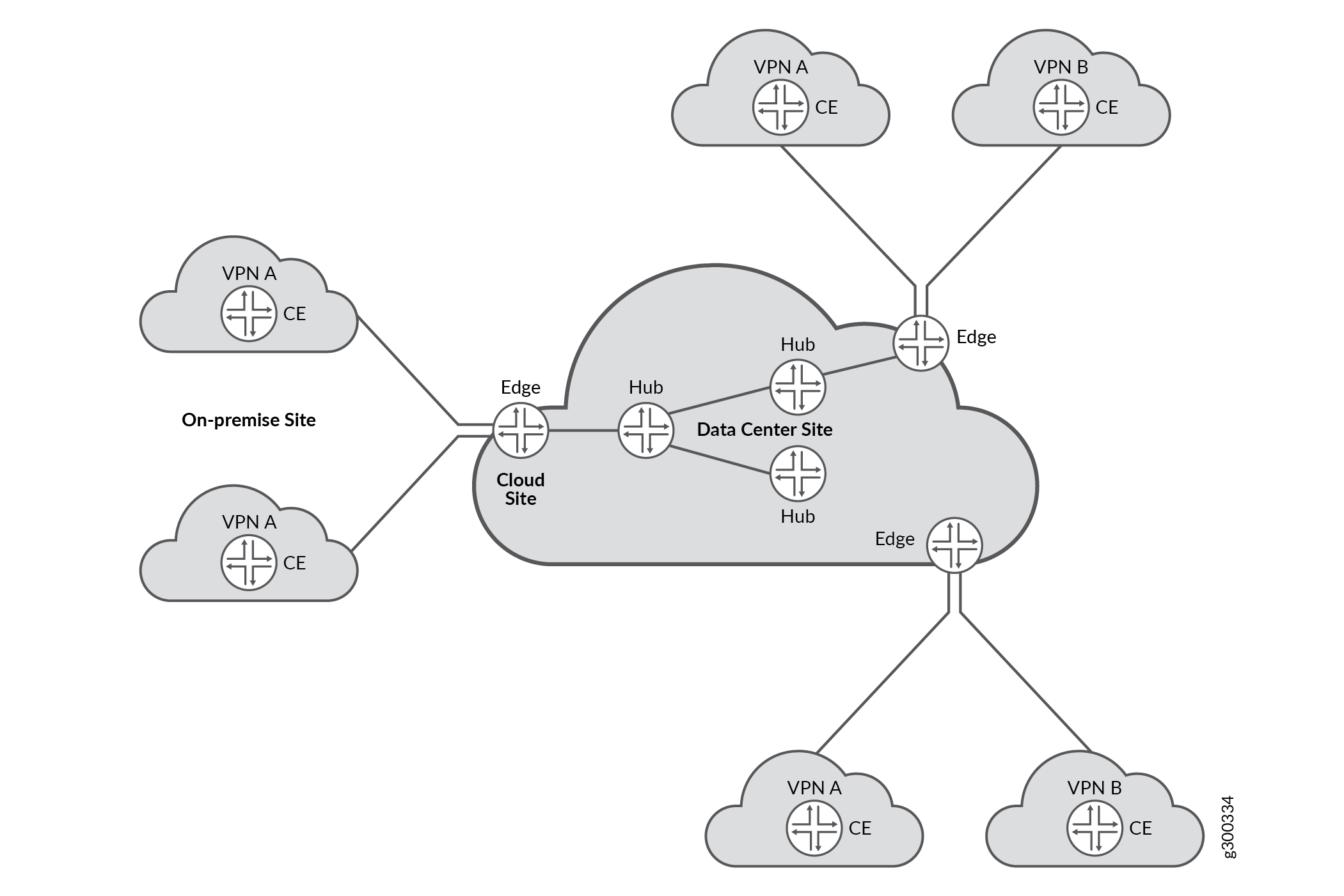
L3VPN networks are identified at a site (CPE device) as a set of VRF instances. The VRF instances at a site belonging to a L3VPN network at a site are used for application policy based forwarding. Firewall flow session handling has enhanced to support mid-stream traffic switching between these VRF instances based on application based steering policies. The VRF instances which are logically part of a given L3VPN network can be configured as a VRF group. Existing firewall, NAT configuration commands have been enhanced to support operations on VRF group.
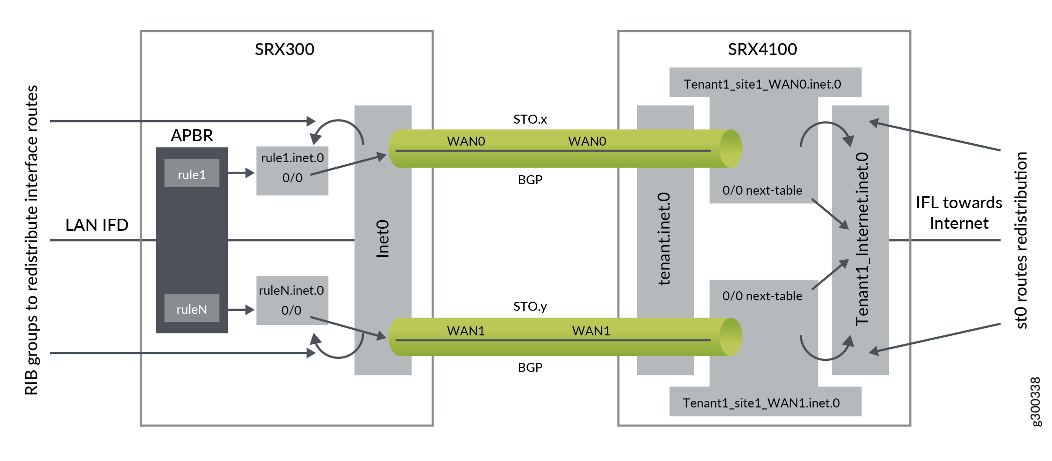
The below figure describes how traffic steering within an L3VPN is done across multiple VRFs based on APBR policies.
When you configure the VRF groups using VRF instances, a VRF group-ID is generated. These VRF groups are used in the following modules to control SD-WAN L3VPN:
-
Security Policy - For policy control.
-
Flow - To search policies based on VRF group names, along with source or destination zone, source or destination IP address, and protocol. Hence, sessions are created using VRF groups as one of differentiator.
-
NAT - To support NAT rules based on VRF group names.
-
ALG - To create ALG sessions using VRF groups as one of differentiator.
The functionality of the VRF groups:
-
It allows a session to switch between two MPLS VRFs.
-
When the VRF instances are part of the same VRF group, security features such as flow, policy, NAT, or ALG modules treat the VRF instances similarly.
-
When you configure the VRF groups using VRF instances, a VRF group-ID is generated. This group-ID is stored in session for identifying the VRF group of a particular VRF instance.
VRF group is introduced to support L3VPN MPLS based sessions in SD-WAN network. It is used to control the MPLS L3VPN traffic in policy, flow, NAT and ALG modules when there are overlapping or no overlapping IP network addresses in the MPLS L3VPN network.
If the traffic pass between non MPLS L3VPN networks, VRF groups are not configured. When
VRF groups are not configured, the VRF group-ID will be zero or the policy will use the
option any for VRF group.
The purpose of VRF groups is:
-
To differentiate L3VPN sessions between MPLS L3VPN network.
-
To have policy and NAT control between MPLS L3VPN network.
Types of VRF groups
There are two important VRF group in L3VPN network are:
-
Source-VRF group
-
Destination-VRF group
To understand which VRF instances can be grouped together for Source-VRF group or Destination-VRF group, use the following information:
-
Source-VRF instances—List of VRF instances that negotiates different MPLS paths to the same in-bound destination.
-
Destination-VRF instances— List of VRF instances that contain the destination routes for a given L3VPN traffic.
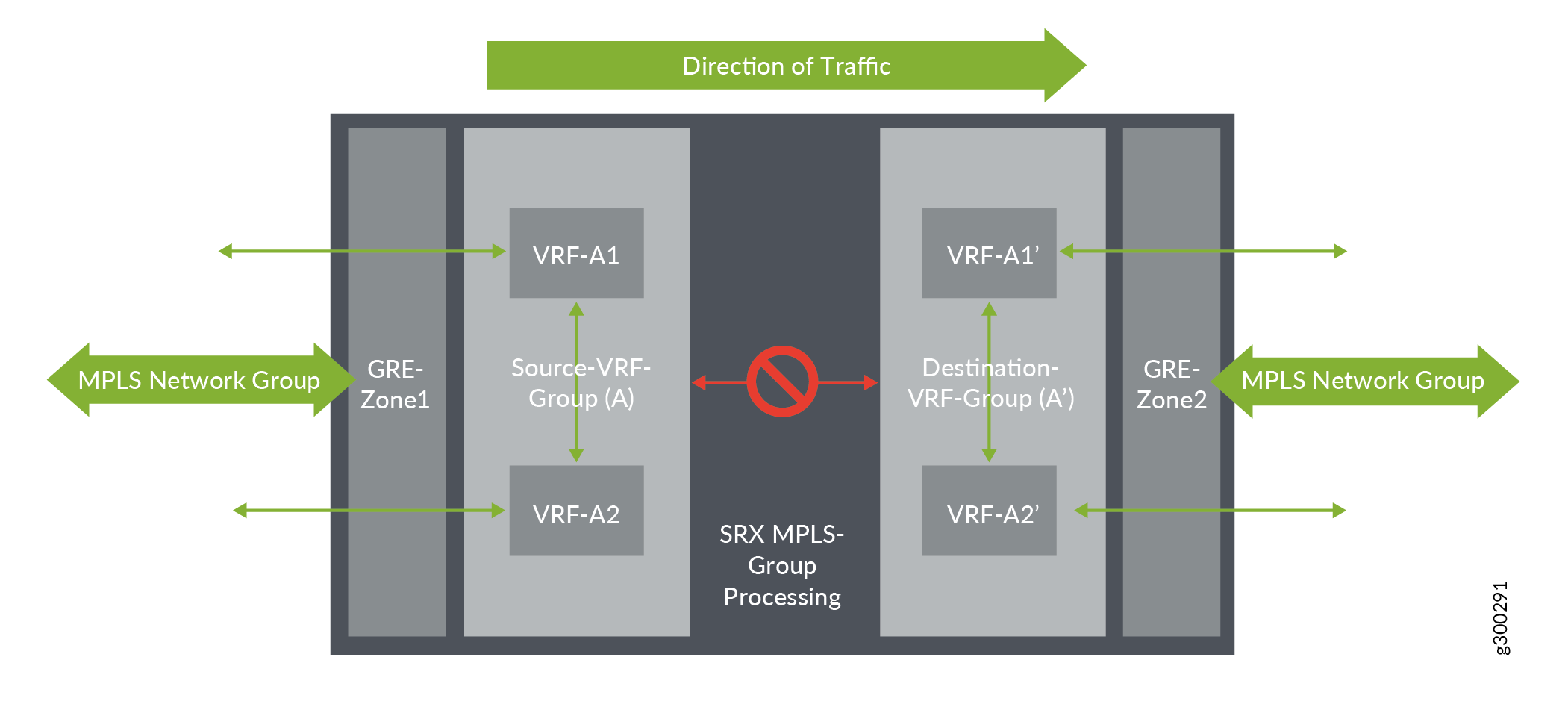
If the traffic is initiated in the opposite direction, the VRF groups switch roles with respect to the direction of the traffic.
VRF Movement
From Figure 3, the initial traffic flow for a session establishment is from left to right. The traffic enters GRE-Zone1, then enters Source-VRF group (A) and passes through Destination-VRF group (A’) before it exits through GRE_Zone2.
Similarly, the policy search is initiated from GRE_Zone1->Source-VRF
group(A)->Destination-VRF group->(A’)->GRE_Zone2 and the flow
sessions is set-up, using Source-VRF group (A) and Destination-VRF group (A) as an
additional key values in sessions. When the flow sessions are done using VRF groups,
traffic can switch (re-route) from one VRF to another VRF within Group.
VRF group-ID
For storing the VRF group-ID, a 16-bits number is used in a session key data structure.
Configuring VRF groups
To configure a VRF group, use the following steps:
-
List the VRF instances that needs to be grouped.
-
Assign a name to the VRF group.
-
Apply the VRF instances and the VRF group name in the CLI command
set
                     security l3vpn vrf-group group-name vrf
                        vrf1 vrf vrf2
The source and destination VRF groups are configured separately based on different context.
-
Source VRF group—The source VRF group for routing-instance is associated with MPLS packet. When the device receives a MPLS packet, the packet is decoded and mapped to LSI interface. The LSI interface contains the routing table information that helps in identifying the VRF group details.
-
Destination VRF group—During first-path flow processing of packet for a new session, the destination route information is required to route the packet to the next-hop or interface. Flow searches the routing table to get the route information. When the received route information points to MPLS as next-hop, then the VRF of this route is used to identify the destination VRF group.
The source and destination VRF groups are same in some cases when you prefer to control all the related VRFs in a L3VPN network.
VRF group Operations
When a VRF group is configured, a Group-ID is created which is unique for different VRF groups. You can perform different operations such as adding, removing, or modifying a VRF to a VRF group.
Adding VRF to a VRF group
When a VRF is added to a VRF group, the corresponding VRF group-ID is assigned to the VRF. When you add a VRF to VRF group, remember the following:
-
A VRF can be added to only one VRF group. It cannot be a part of multiple VRF groups.
-
A maximum of 32 VRFs are be configured in a VRF group.
-
When a VRF is added, it impacts the existing session and a new session is created as per policy.
-
When new sessions are created after adding a new VRF to VRF group, the sessions use the new VRF group-ID of the new VRF.
Removing VRF from a VRF group
When a VRF is removed from a VRF group, the VRF group-ID of that VRF group changes to zero but the VRF will still be available in the device. When you remove a VRF from a VRF group, it impacts the existing sessions in two ways:
-
Impacting existing sessions—When a VRF is removed from the VRF group, the existing session is removed and a new session will be created as per policy
-
Match Traffic—When a VRF is removed from VRF group, the VRF group-ID for that VRF changes to zero and hence will not match the session. The packet drops and a new session is created as per policy.
When a VRF is removed from the VRF group, the new session that is processed using the impacted VRF installs a new VRF group-ID. This VRF group-ID will be zero, or a new Group-ID is created if you add the VRF to a new VRF group
Modifying VRF group
Modifying a VRF group involves the following operations:
-
Changing VRF group name: When you change the VRF group name, the policy module scans the existing sessions to verify if the new VRF group name matches the existing rules.
-
Adding VRF to VRF group: When a VRF is added to a VRF group, the corresponding VRF group-ID is assigned to the VRF.
-
Removing VRF from VRF group: When a VRF is removed from a VRF group, the VRF group-ID of that VRF changes to zero and still the VRF will be available in the device.
Removing VRF group
When you remove a VRF group using CLI, a session scan will be performed on the existing sessions to match the VRF group that is removed. If the session match the removed VRF group, then that session is removed from the device by setting an invalid timeout. For sessions that does not match the removed VRP-Group-ID are not impacted.
First Path Processing using VRF Group
To process a packet, the first path processing performs the following:
-
MPLS Decoder—When flow receives a MPLS or non-MPLS packet, the packet is processed to retrieve the details of the incoming packet, interface, and routing-instance of the incoming interface.
-
FBF configuration—When you configure FBF rules to re-direct the incoming packets to different routing-instance, the FBF rule finds the routing-instance information and pass the FBF routing-instance information instead of packet incoming interface routing-instance. This FBF VRF should be a part of VRF group to control the L3VPN network.
-
Initialize Routing-Table—When the flow receives the packet, the initial routing-table for the packet is created. If the FBF configuration matches the firewall filters, then the routing-instance information from FBF is used for route look-up. Else, flow uses the incoming interface routing-instance information for route look-up.
-
Finding Source VRF group—If the incoming packet is from MPLS network, then the packet is mapped to the VRF instance of source VRF group. If the incoming packet is not MPLS packet, then the source VRF group id is zero.
-
Destination NAT using VRF group—Flow checks if the destination IP needs NAT translation. Destination NAT supports two types of match criteria for VRF:
-
NAT rule search using VRF routing-group.
-
NAT rule result using VRF routing-instance and NAT information.
-
-
Destination Route—The route look-up which is done in initial route table is used to identify the outgoing interface and destination-VRF information. This information is used in policy search and session installation.
-
Final next-hop—The first step in finding destination route is to find final the next-hop of the pointed route. Using this next-hop, flow will check if the next-hop points to MPLS network or not. If it is not pointing to MPLS network, the destination VRF group will be zero.
-
Destination VRF group— When the destination VRF is identified, the destination VRF Group-ID is initialized. If the destination VRF is not assigned to any group, it is set to zero.
-
First Path Policy Search—Flow performs policy search to check if the packet needs to be permitted or denied. Flow gathers the 5-tuple policy-key information and VRF information and this information is used by policy search module to find the appropriate VRF policy.
-
Source NAT using VRF group—Flow session does source NAT using source VRF group NAT rule search. Source-NAT supports two types of NAT search criteria.
-
Source-NAT rule search using VRF group.
-
Static-NAT rule search using VRF group or VRF instance.
-
-
Static NAT using VRF group or VRF instance—Static NAT supports routing-group in rule-set and routing-instance in rule with VRF type.
-
When static NAT matches as destination NAT translation for a given IP packet, the VRF routing-group will be one of the match criteria and the VRF routing-instance ill be used as destination routing table.
-
When static NAT matches as source NAT translation for a given IP packet, the VRF routing-instance will be one of the match criteria.
-
-
Session Installation using VRF group—During session installation process, source VRF group-ID is stored in forward-wing indicating that the wing points MPLS network. The destination VRF group-ID that is found from route look-up is stored in reverse-wing indicating that the wing points MPLS network.
-
Re-routing using VRF group—Once the session is established using VRF group information, re-route is initiated if the interface is down or initial route is not available. These changed routes should be part of same VRF group (Source-VRF group/Destination-VRF group), in which the session is initially established on either side. Else, traffic will not match session and future traffic of session might get dropped or create new sessions as per policy.
Fast Path Processing using VRF Group
The fast path processing performs the following steps to process a packet.
-
MPLS Decoder—When a packet MPLS or non-MPLS packet is received, the packet undergoes MPLS processing. When the processing is complete, the flow receives the details of the incoming packet, interface, and routing-instance of the incoming interface.
-
FBF configuration—When you configure FBF rules to re-direct the incoming packets to different routing-instance, the FBF rule finds the routing-instance information and pass the FBF routing-instance information instead of packet incoming interface routing-instance. This FBF VRF should be a part of VRF group to control the L3VPN network.
-
Session look-up using VRF Group-ID—During session look-up process, flow checks whether to pass the VRF Group-ID in session key for look-up. If the incoming interface is MPLS, flow will pass the VRF Group-ID information of the mapped VRF routing-instance to session key along with other key tuple information. If the incoming interface is not MPLS, the VRF Group-ID will be zero.
-
Session Route change—If the route changes for session in mid-stream, flow checks for the new VRF that belongs to this route. If the new VRF Group-ID differs from the VRF Group-ID of the session, then the route will not be processed and the future packets are dropped. Hence, for re-routing the new route should belong to a VRF that belongs to session VRF Group.
-
VRF Group policy change—When VRF group session policy is changed due to policy attributes such as zone/interface/IP/Source-VRF group/Destination-VRF group, the policy will be re-matched for the same session by supplying policy 5-tuple along with source VRF group and destination VRF group values to check if the policy is valid or not. Upon re-match, if policy does not match the session information, then the session terminates.
-
VRF session display—Source-VRF Group and Destination-VRF Group are displayed in session output display to differentiate different VRF group for the same tuple.
-
High Availability—High availability is supported with no behavior change when additional VRF group-ID information is synchronized to the HA peer node for differentiating different VRF group in the session
Flow Processing with VRF-Aware Zones
In session management, we now integrate zone IDs into the session tuple. The virtual routing and forwarding (VRF) group ID is replaced by the zone ID, which the flow sessions caches and passes down for further processing.
Zone-based session management maintains alignment with network configurations by accurately associating sessions with the correct interface and overlay zones. When a zone configuration change, such as an alteration to an interface or overlay zone, the system automatically terminates sessions linked to the affected zones, maintaining consistency and reliability across the session management framework. Only the sessions associated with modified zones are terminated, while those linked to unaffected zones continue to function seamlessly.