Security Policies for a VRF Routing Instance
Overview
A security policy is a set of statements that controls traffic from a specified source to a specified destination using a specified service. A policy permits, denies, or tunnels specified types of traffic unidirectionally between two points. Security policies enforce a set of rules for transit traffic, identifying which traffic can pass through the firewall and the actions taken on the traffic as it passes through the firewall. Actions for traffic matching the specified criteria include permit and deny.
When an SRX Firewall receives a packet that matches the specifications, it performs the action specified in the policy.
Controlling Traffic in SD-WAN Architecture
In an SD-WAN, the SRX Firewall can be configured in a hub and spoke location. You can permit or deny virtual routing and forwarding (VRF) based traffic that enters the device from overlay tunnels by applying firewall policies. You can configure the SRX Firewall to permit or deny traffic that is sent to a VRF instance. Configuring the device at the hub location enables you to control all traffic at one location, and provide access to specific network services by applying firewall policies.
Each security policy consists of:
-
A unique name for the policy.
-
A
from-zoneand ato-zone, for example:user@host# set security policies from-zone GRE_Zone-GE_Zone to-zone GRE_Zone. -
A set of match criteria defining the conditions that must be satisfied to apply the policy rule. The match criteria are based on a source IP address, destination IP address, and applications. The user identity firewall provides greater granularity by including an additional tuple, such as source-identity, as part of the policy statement.
-
A set of actions to be performed in case of a match—permit or deny.
-
A set of source VRF group.
-
A set of destination VRF group.
The configuration options for the source and destination VRF instances are optional. You can configure either the source VRF or a destination VRF, but we recommend that you do not configure both source VRF and destination VRF. The main reason for configuring the source VRF or destination VRF is to differentiate different MPLS labels going through a shared physical network interface.
Table 1 lists when to configure the source VRF and destination VRF.
|
Network Type from Source to Destination |
Recommended to Configure Source VRF |
Recommended to Configure Destination VRF |
VRF Policy Differentiated By |
|---|---|---|---|
|
IP network to IP network |
No |
No |
Zones |
|
IP network to MPLS network |
No |
Yes |
Destination VRF |
|
MPLS network to IP network |
Yes |
No |
Source VRF |
|
MPLS network to MPLS network without destination NAT |
Yes |
No |
Source VRF |
|
MPLS network to MPLS network with destination NAT |
Yes |
Yes |
Source VRF and Destination VRF |
Understanding Security Policy Rules
A security policy applies security rules to the transit traffic within a context
(from-zone to to-zone). Each policy is uniquely
identified by its name. The traffic is classified by matching its source and destination
zones, the source and destination addresses, the application, the source VRF, and the
destination VRF that the traffic carries in its protocol headers with the policy
database in the data plane.
Each policy is associated with the following characteristics:
-
A source zone
-
A destination zone
-
One or many source address names or address set names
-
One or many destination address names or address set names
-
One or many application names or application set names
-
One or many source VRF instances, for example, the VRF routing instance associated with an incoming packet
-
One or many destination VRF instances in which the MPLS next hop or destination address route is located
These characteristics are called the match criteria. Each policy also has actions associated with it: permit, deny, and reject. You have to specify the match condition arguments when you configure a policy, source address, destination address, application name, source VRF, and destination VRF.
You can configure either source VRF or destination VRF, but not recommended to configure both source VRF and destination VRF. The main reason for configuring source VRF and destination VR is to differentiate different MPLS labels going through a shared physical network interface. If the source VRF and destination VRF are not configured, then the device determines the source and destination VRF as any.
Example: Configuring a Security Policy to Permit or Deny VRF-Based Traffic from MPLS Network to an IP Network
This example shows how to configure a security policy to permit traffic and deny traffic using the source VRF.
Requirements
-
Understand how to create a security zone. SeeExample: Creating Security Zones.
-
Supported SRX Series Firewall with any supported Junos OS release. See Virtual Routing (VRF) and Security Policies.
-
Configure network interfaces on the device. See Interfaces User Guide for Security Devices.
Overview
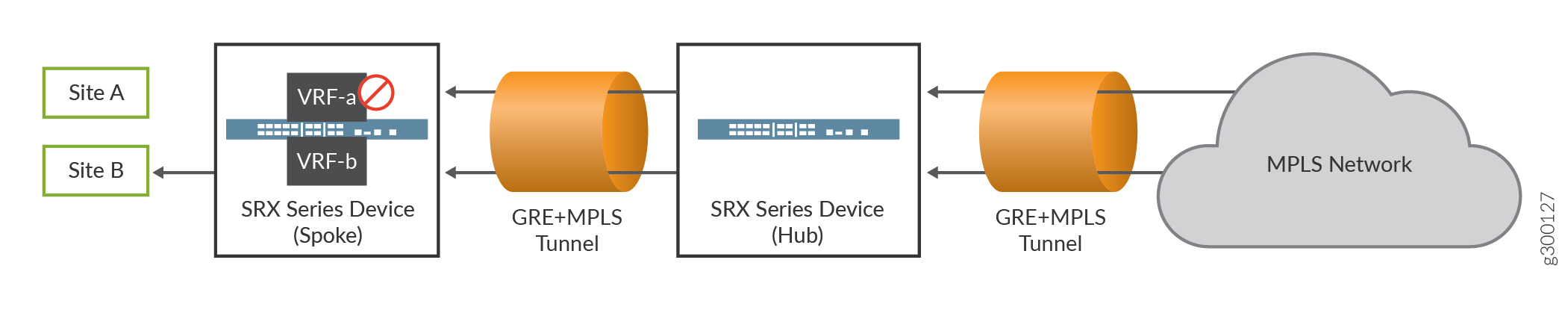
In Junos OS, security policies enforce rules for transit traffic, in terms of what traffic can pass through the device and the actions that need to take place on the traffic as it passes through the device. In Figure 1, an SRX Firewall is deployed in an SD-WAN to control traffic using the source VRF. Traffic from the MPLS network is sent to site A and site B of the IP network. As per the network requirement, site A traffic should be denied, and only site B traffic should be permitted.
This configuration example shows how to:
-
Deny traffic to VRF-a (from GRE_Zone-GE_Zone to GRE_Zone)
-
Permit traffic to VRF-b (from GRE_Zone-GE_Zone to GRE_Zone)
In this example, the source VRF is configured. We recommend that you configure the source VRF when the destination network points to the MPLS network.
Configuration
Procedure
CLI Quick Configuration
To quickly configure this example, copy the following commands, paste them into
a text file, remove any line breaks, change any details necessary to match your
network configuration, copy and paste the commands into the CLI at the
[edit] hierarchy level, and then enter
commit from configuration mode.
                     set routing-instances VRF-a instance-type vrf


                     set routing-instances VRF-a route-distinguisher 10:200


                     set routing-instances VRF-a vrf-target target:100:100


                     set routing-instances VRF-a vrf-table-label


                     set routing-instances VRF-b instance-type vrf


                     set routing-instances VRF-b route-distinguisher 20:200


                     set routing-instances VRF-b vrf-target target:200:100


                     set routing-instances VRF-b vrf-table-label


                     set security policies from-zone GRE_Zone-GE_Zone to-zone GRE_Zone policy vrf-a_policy match source-address any


                     set security policies from-zone GRE_Zone-GE_Zone to-zone GRE_Zone policy vrf-a_policy match destination-address any


                     set security policies from-zone GRE_Zone-GE_Zone to-zone GRE_Zone policy vrf-a_policy match application any


                     set security policies from-zone GRE_Zone-GE_Zone to-zone GRE_Zone policy vrf-a_policy match source-l3vpn-vrf-group  VRF-a


                     set security policies from-zone GRE_Zone-GE_Zone to-zone GRE_Zone policy vrf-a_policy then deny


                     set security policies from-zone GRE_Zone-GE_Zone to-zone GRE_Zone policy vrf-b_policy match source-address any


                     set security policies from-zone GRE_Zone-GE_Zone to-zone GRE_Zone policy vrf-b_policy match destination-address any


                     set security policies from-zone GRE_Zone-GE_Zone to-zone GRE_Zone policy vrf-b_policy match application any


                     set security policies from-zone GRE_Zone-GE_Zone to-zone GRE_Zone policy vrf-b_policy match source-l3vpn-vrf-group VRF-b


                     set security policies from-zone GRE_Zone-GE_Zone to-zone GRE_Zone policy vrf-b_policy then permit
Step-by-Step Procedure
The following example requires you to navigate various levels in the configuration hierarchy. For information about navigating the CLI, see Using the CLI Editor in Configuration Mode in the Junos OS CLI User Guide.
-
Layer 3 VPNs require a VRF table for distributing routes within the networks. Create a VRF instance and specify the value vrf.
[edit routing-instances] user@host# set VRF-a instance-type vrf user@host# set VRF-b instance-type vrf -
Assign a route distinguisher to the routing instance.
[edit routing-instances] user@host# set VRF-a route-distinguisher 10:200 user@host# set VRF-b route-distinguisher 20:200 -
Create a community policy to import or export all routes.
[edit routing-instances] user@host# set VRF-a vrf-target target:100:100 user@host# set VRF-b vrf-target target:200:100 -
Assign a single VPN label for all the routes in the VRF.
[edit routing-instances] user@host# set VRF-a vrf-table-label user@host# set VRF-b vrf-table-label -
Create a security policy to deny VRF-a traffic.
[edit security policies from-zone GRE_Zone-GE_Zone to-zone GRE_Zone] user@host# set policy vrf-a_policy match source-address any user@host# set policy vrf-a_policy match destination-address any user@host# set policy vrf-a_policy match application any user@host# set policy vrf-a_policy match source-l3vpn-vrf-group VRF-a user@host# set policy vrf-a_policy then deny -
Create a security policy to permit VRF-b traffic.
[edit security policies from-zone GRE_Zone-GE_Zone to-zone GRE_Zone] user@host# set policy vrf-b_policy match source-address any user@host# set policy vrf-b_policy match destination-address any user@host# set policy vrf-b_policy match application any user@host# set policy vrf-b_policy match source-l3vpn-vrf-group VRF-b user@host# set policy vrf-b_policy then permitNote:If no destination VRF group is configured then the device considers the traffic passes from VRF-a to any-vrf.
Results
From configuration mode, confirm your configuration by entering the
show security policies and show
routing-instances commands. If the output does not display the
intended configuration, repeat the configuration instructions in this example
to correct it.
[edit]
user@host# show security policies
from-zone GRE_Zone-GE_Zone to-zone GRE_Zone {
    policy vrf-a_policy {
        match {
            source-address any;
            destination-address any;
            application any;
            source-l3vpn-vrf-group VRF-a;
        }
        then {
            deny;
        }
    }
    policy vrf-b_policy {
        match {
            source-address any;
            destination-address any;
            application any;
            source-l3vpn-vrf-group VRF-b;
        }
        then {
            permit;
        }
    }
[edit]
user@host# show routing-instances
    VRF-a {
        instance-type vrf;
        route-distinguisher 10:200;
        vrf-target target:100:100;
        vrf-table-label;
    }
    VRF-b {
        instance-type vrf;
        route-distinguisher 20:200;
        vrf-target target:200:100;
        vrf-table-label;
    }
}
If you are done configuring the device, enter commit from
configuration mode.
Verification
Verifying Policy Configuration
Purpose
Verify information about security policies.
Action
From operational mode, enter the show security policies
command to display a summary of all the security policies configured on the
device.
user@root> show security policies
Default policy: permit-all
From zone: GRE_Zone-GE_Zone, To zone: GRE_Zone
  Policy: vrf-a_policy, State: enabled, Index: 4, Scope Policy: 0, Sequence number: 1
    Source vrf: VRF-a
    destination vrf: any
    Source addresses: any
    Destination addresses: any
    Applications: any
    Action: deny
  Policy: vrf-b_policy, State: enabled, Index: 5, Scope Policy: 0, Sequence number: 2
    Source vrf: VRF-b
    destination vrf: any
    Source addresses: any
    Destination addresses: any
    Applications: any
    Action: permit
Example: Configuring a Security Policy to Permit VRF-Based Traffic from an IP Network to an MPLS Network
This example shows how to configure a security policy to permit traffic using the destination VRF.
Requirements
-
Understand how to create a security zone. See Example: Creating Security Zones.
-
Supported SRX Series Firewall with any supported Junos OS release. See Virtual Routing (VRF) and Security Policies.
-
Configure network interfaces on the device. See the Interfaces User Guide for Security Devices.
Overview
In Junos OS, security policies enforce rules for transit traffic, in terms of what traffic can pass through the device and the actions that need to take place on the traffic as it passes through the device.
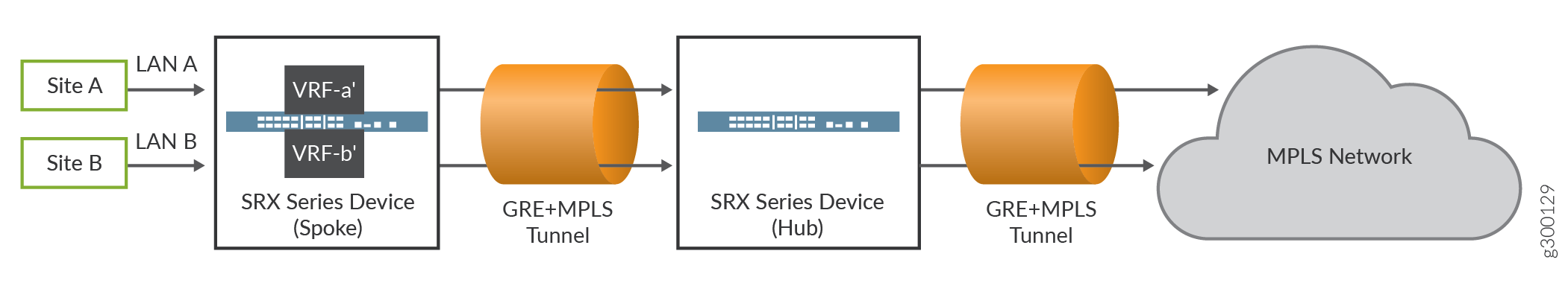
In this example, an SRX Firewall is deployed in an SD-WAN architecture to control traffic using the destination VRF. You need to configure policies to control the traffic. The default policy does not support VRF options. Traffic from the IP network, that is site A and site B, is sent to the MPLS network. By configuring the policies, you can permit both the traffic from site A and site B to the MPLS network.
In Figure 2, the source VRF is not configured as the LAN interface does not belong to an MPLS network. We recommend that you configure the destination VRF when the destination network points to the MPLS network.
Configuration
Procedure
CLI Quick Configuration
To quickly configure this example, copy the following commands, paste them into
a text file, remove any line breaks, change any details necessary to match your
network configuration, copy and paste the commands into the CLI at the
[edit] hierarchy level, and then enter
commit from configuration mode.
                     set routing-instances VRF-a’ instance-type vrf


                     set routing-instances VRF-a’ route-distinguisher 10:200


                     set routing-instances VRF-a’ vrf-target target:100:100


                     set routing-instances VRF-a’ vrf-table-label


                     set routing-instances VRF-b’ instance-type vrf


                     set routing-instances VRF-b’ route-distinguisher 20:200


                     set routing-instances VRF-b’ vrf-target target:200:100


                     set routing-instances VRF-b’ vrf-table-label


                     set security policies from-zone LAN-a_Zone to-zone GRE_Zone policy vrf-a_policy match source-address any


                     set security policies from-zone LAN-a_Zone to-zone GRE_Zone policy vrf-a_policy match destination-address any


                     set security policies from-zone LAN-a_Zone to-zone GRE_Zone policy vrf-a_policy match application any


                     set security policies from-zone LAN-a_Zone to-zone GRE_Zone policy vrf-a_policy match destination-l3vpn-vrf-group VRF-a’


                     set security policies from-zone LAN-a_Zone to-zone GRE_Zone policy vrf-a_policy then permit


                     set security policies from-zone LAN-b_Zone to-zone GRE_Zone policy vrf-b_policy match source-address any


                     set security policies from-zone LAN-b_Zone to-zone GRE_Zone policy vrf-b_policy match destination-address any


                     set security policies from-zone LAN-b_Zone to-zone GRE_Zone policy vrf-b_policy match application any


                     set security policies from-zone LAN-b_Zone to-zone GRE_Zone policy vrf-b_policy match destination-l3vpn-vrf-group VRF-b’


                     set security policies from-zone LAN-b_Zone to-zone GRE_Zone policy vrf-b_policy then permit
Step-by-Step Procedure
The following example requires you to navigate various levels in the configuration hierarchy. For information about navigating the CLI, see Using the CLI Editor in Configuration Mode in the Junos OS CLI User Guide.
To configure a policy to permit traffic from the IP network to the MPLS network using the destination VRF:
-
Layer 3 VPNs require a VRF table for distributing routes within the networks. Create a VRF instance and specify the value vrf.
[edit routing-instances] user@host# set VRF-a’ instance-type vrf user@host# set VRF-b’ instance-type vrf -
Assign a route distinguisher to the routing instance.
[edit routing-instances] user@host# set VRF-a’ route-distinguisher 10:200 user@host# set VRF-b’ route-distinguisher 20:200 -
Create a community policy to import or export all routes.
[edit routing-instances] user@host# set VRF-a’ vrf-target target:100:100 user@host# set VRF-b’ vrf-target target:200:100 -
Assign a single VPN label for all the routes in the VRF.
[edit routing-instances] user@host# set VRF-a’ vrf-table-label user@host# set VRF-b’ vrf-table-label -
Create a security policy to permit VRF-a’ traffic from the IP network.
[edit security policies from-zone LAN-a_Zone to-zone GRE_Zone] user@host# set policy vrf-a_policy match source-address any user@host# set policy vrf-a_policy match destination-address any user@host# set policy policy vrf-a_policy match application any user@host# set policy vrf-a_policy match destination-l3vpn-vrf-group VRF-a’ user@host# set policy vrf-a_policy then permit -
Create a security policy to permit VRF-b’ traffic from the IP network.
[edit security policies from-zone LAN-b_Zone to-zone GRE_Zone]
user@host# set policy vrf-b_policy match source-address any
user@host# set policy vrf-b_policy match destination-address any
user@host# set policy vrf-b_policy match application any
user@host# set policy vrf-b_policy match destination-l3vpn-vrf-group VRF-b’
user@host# set policy vrf-b_policy then permit
Results
From configuration mode, confirm your configuration by entering the
show security policies and show
routing-instances commands. If the output does not display the
intended configuration, repeat the configuration instructions in this example
to correct it.
[edit]
user@host# show security policies
    from-zone LAN-a_Zone to-zone GRE_Zone {
        policy vrf-a_policy {
            match {
                source-address any;
                destination-address any;
                application any;
                destination-l3vpn-vrf-group "VRF-a'";
            }
            then {
                permit;
            }
        }
    }
    from-zone LAN-b_Zone to-zone GRE_Zone {
        policy vrf-b_policy {
            match {
                source-address any;
                destination-address any;
                application any;
                destination-l3vpn-vrf-group "VRF-b'";
            }
            then {
                permit;
            }
        }
    }
[edit]
user@host# show routing-instances
    VRF-a’ {
        instance-type vrf;
        route-distinguisher 10:200;
        vrf-target target:100:100;
        vrf-table-label;
    }
    VRF-b’ {
        instance-type vrf;
        route-distinguisher 20:200;
        vrf-target target:200:100;
        vrf-table-label;
    }
If you are done configuring the device, enter commit from
configuration mode.
Verification
Verifying Policy Configuration
Purpose
Verify that the security policy permits VRF-based traffic from the IP network to the MPLS network.
Action
From operational mode, enter the show security policies
command to display a summary of all the security policies configured on the
device.
user@host> show security policies
From zone: LAN-a_Zone, To zone: GRE_Zone
  Policy: vrf-a_policy, State: enabled, Index: 4, Scope Policy: 0, Sequence number: 1
    Source vrf: any
    destination vrf: VRF-a'
    Source addresses: any
    Destination addresses: any
    Applications: any
    Action: permit
From zone: LAN-b_Zone, To zone: GRE_Zone
  Policy: vrf-b_policy, State: enabled, Index: 5, Scope Policy: 0, Sequence number: 1
    Source vrf: any
    destination vrf: VRF-b'
    Source addresses: any
    Destination addresses: any
    Applications: any
    Action: permit
Example: Configuring a Security Policy to Permit VRF-Based Traffic from an MPLS Network to an MPLS Network over GRE without NAT
This example shows how to configure a security policy to permit traffic using the source VRF.
Requirements
-
Understand how to create a security zone. See Example: Creating Security Zones.
-
Supported SRX Firewall with Junos OS Release 15.1X49-D160 or later. This configuration example is tested for Junos OS Release 15.1X49-D160.
-
Configure network interfaces on the device. See the Interfaces User Guide for Security Devices.
Overview
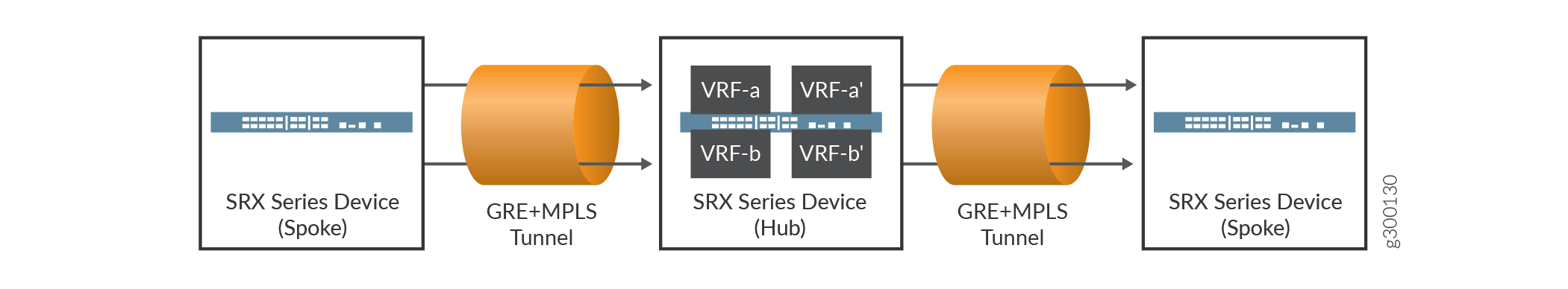
In Junos OS, security policies enforce rules for transit traffic, in terms of what traffic can pass through the device and the actions that need to take place on the traffic as it passes through the device. In Figure 3, an SRX Firewall is deployed in an SD-WAN architecture to control traffic using the source VRF. You need to configure policies to control the traffic. You can permit traffic from an MPLS network to another MPLS network by configuring policies.
We recommend that you configure both the source VRF and the destination VRF when the source and destination are from the MPLS network.
Configuration
Procedure
CLI Quick Configuration
To quickly configure this example, copy the following commands, paste them into
a text file, remove any line breaks, change any details necessary to match your
network configuration, copy and paste the commands into the CLI at the
[edit] hierarchy level, and then enter
commit from configuration mode.
                     set routing-instances VRF-a instance-type vrf


                     set routing-instances VRF-a route-distinguisher 10:200


                     set routing-instances VRF-a vrf-target target:100:100


                     set routing-instances VRF-a vrf-table-label


                     set routing-instances VRF-b instance-type vrf


                     set routing-instances VRF-b route-distinguisher 20:200


                     set routing-instances VRF-b vrf-target target:200:100


                     set routing-instances VRF-b vrf-table-label


                     set routing-instances VRF-a’ instance-type vrf


                     set routing-instances VRF-a’ route-distinguisher 30:200


                     set routing-instances VRF-a’ vrf-target target:300:100


                     set routing-instances VRF-a’ vrf-table-label


                     set routing-instances VRF-b’ instance-type vrf


                     set routing-instances VRF-b’ route-distinguisher 40:200


                     set routing-instances VRF-b’ vrf-target target:400:100


                     set routing-instances VRF-b’ vrf-table-label


                     set security policies from-zone GRE-1_Zone to-zone GRE-2_Zone policy vrf-a_policy match source-address any


                     set security policies from-zone GRE-1_Zone to-zone GRE-2_Zone policy vrf-a_policy match destination-address any


                     set security policies from-zone GRE-1_Zone to-zone GRE-2_Zone policy vrf-a_policy match application any


                     set security policies from-zone GRE-1_Zone to-zone GRE-2_Zone policy vrf-a_policy match source-l3vpn-vrf-group  VRF-a


                     set security policies from-zone GRE-1_Zone to-zone GRE-2_Zone policy vrf-a_policy match destination-l3vpn-vrf-group VRF-a’


                     set security policies from-zone GRE-1_Zone to-zone GRE-2_Zone policy vrf-a_policy then permit


                     set security policies from-zone GRE-1_Zone to-zone GRE-2_Zone policy vrf-b_policy match source-address any


                     set security policies from-zone GRE-1_Zone to-zone GRE-2_Zone policy vrf-b_policy match destination-address any


                     set security policies from-zone GRE-1_Zone to-zone GRE-2_Zone policy vrf-b_policy match application any


                     set security policies from-zone GRE-1_Zone to-zone GRE-2_Zone policy vrf-b_policy match source-l3vpn-vrf-group  VRF-b


                     set security policies from-zone GRE-1_Zone to-zone GRE-2_Zone policy vrf-b_policy match destination-l3vpn-vrf-group VRF-b’


                     set security policies from-zone GRE-1_Zone to-zone GRE-2_Zone policy vrf-b_policy then permit
Step-by-Step Procedure
The following example requires you to navigate various levels in the configuration hierarchy. For information about navigating the CLI, see Using the CLI Editor in Configuration Mode in the Junos OS CLI User Guide.
To configure a policy to permit traffic from an MPLS network to an MPLS network using source VRF:
-
Layer 3 VPNs require a VRF table for distributing routes within the networks. Create a VRF instance and specify the value vrf.
[edit routing-instances] user@host# set VRF-a instance-type vrf user@host# set VRF-b instance-type vrf user@host# set VRF-a’ instance-type vrf user@host# set VRF-b’ instance-type vrf -
Assign a route distinguisher to the routing instance.
[edit routing-instances] user@host# set VRF-a route-distinguisher 10:200 user@host# set VRF-b route-distinguisher 20:200 user@host# set VRF-a’ route-distinguisher 30:200 user@host# set VRF-b’ route-distinguisher 40:200 -
Create a community policy to import or export all routes.
[edit routing-instances] user@host# set VRF-a vrf-target target:100:100 user@host# set VRF-b vrf-target target:200:100 user@host# set VRF-a’ vrf-target target:300:100 user@host# set VRF-b’ vrf-target target:400:100 -
Assign a single VPN label for all the routes in the VRF.
[edit routing-instances] user@host# set VRF-a vrf-table-label user@host# set VRF-a’ vrf-table-label user@host# set VRF-b vrf-table-label user@host# set VRF-b’ vrf-table-label -
Create a security policy to permit VRF-a traffic from the MPLS network.
[edit security policies from-zone GRE-1_Zone to-zone GRE-2_Zone] user@host# set policy vrf-a_policy match source-address any user@host# set policy vrf-a_policy match destination-address any user@host# set policy vrf-a_policy match application any user@host# set policy vrf-a_policy match source-l3vpn-vrf-group VRF-a user@host# set policy vrf-a_policy match destination-l3vpn-vrf-group VRF-a’ user@host# set policy vrf-a_policy then permit -
Create a security policy to permit VRF-b traffic from the MPLS network.
[edit security policies from-zone GRE-1_Zone to-zone GRE-2_Zone]
user@host# set policy vrf-b_policy match source-address any
user@host# set policy vrf-b_policy match destination-address any
user@host# set policy vrf-b_policy match application any
user@host# set policy vrf-b_policy match source-l3vpn-vrf-group VRF-b
user@host# set policy vrf-b_policy match destination-l3vpn-vrf-group VRF-b’
user@host# set policy vrf-b_policy then permit
Results
From configuration mode, confirm your configuration by entering the
show security policies and show
routing-instances commands. If the output does not display the
intended configuration, repeat the configuration instructions in this example
to correct it.
[edit]
user@host# show security policies
    from-zone GRE-1_Zone to-zone GRE-2_Zone {
        policy vrf-a_policy {
            match {
                source-address any;
                destination-address any;
                application any;
                source-l3vpn-vrf-group  VRF-a;
                destination-l3vpn-vrf-group "VRF-a'";
            }
            then {
                permit;
            }
        }
        policy vrf-b_policy {
            match {
                source-address any;
                destination-address any;
                application any;
                source-l3vpn-vrf-grou  VRF-b;
                destination-l3vpn-vrf-group "VRF-b'";
            }
            then {
                permit;
            }
        }
    }
[edit]
user@host# show routing-instances
    VRF-a {
        instance-type vrf;
        route-distinguisher 10:200;
        vrf-target target:100:100;
        vrf-table-label;
    }
    VRF-b {
        instance-type vrf;
        route-distinguisher 20:200;
        vrf-target target:200:100;
        vrf-table-label;
    }
    VRF-a’ {
        instance-type vrf;
        route-distinguisher 30:200;
        vrf-target target:300:100;
        vrf-table-label;
    }
    VRF-b’ {
        instance-type vrf;
        route-distinguisher 40:200;
        vrf-target target:400:100;
        vrf-table-label;
    }
If you are done configuring the device, enter commit from
configuration mode.
Verification
Verifying Policy Configuration
Purpose
Verify that the security policy permits VRF based traffic from the IP network to the MPLS network.
Action
From operational mode, enter the show security policies
command to display a summary of all the security policies configured on the
device.
user@host> show security policies
From zone: GRE-1_Zone, To zone: GRE-2_Zone
  Policy: vrf-a_policy, State: enabled, Index: 7, Scope Policy: 0, Sequence number: 1
    Source vrf: VRF-a
    destination vrf: VRF-a'
    Source addresses: any
    Destination addresses: any
    Applications: any
    Action: permit
  Policy: vrf-b_policy, State: enabled, Index: 8, Scope Policy: 0, Sequence number: 2
    Source vrf: VRF-b
    destination vrf: VRF-b'
    Source addresses: any
    Destination addresses: any
    Applications: any
    Action: permit
Example: Configuring Security Policies Using VRF Routing Instances in an MPLS Network
This example shows how to configure security policies using VRF routing instances.
Requirements
-
Supported SRX Series Firewall with any supported Junos OS release. See Virtual Routing (VRF) and Security Policies.
-
Configure network interfaces on the device. See Interfaces User Guide for Security Devices.
-
Understand how to create a security zone. See Example: Creating Security Zones.
Overview
In this example, you create security policies using virtual routing and forwarding (VRF) instances to isolate traffic traversing in the following networks:
-
An MPLS to a private IP network
-
A Global IP to an MPLS network
MPLS Network to Private IP Network
Procedure
Step-by-Step Procedure
-
Layer 3 VPNs require a VRF table for distributing routes within the networks. Create a VRF instance and specify the value vrf.
[edit routing-instances] user@host#set VRF-a instance-type vrf user@host#set VRF-b instance-type vrf -
Assign a route distinguisher to the routing instance.
[edit routing-instances] user@host# set VRF-a route-distinguisher 10:200 user@host# set VRF-b route-distinguisher 20:200 -
Create a community policy to import or export all routes.
[edit routing-instances] user@host# set VRF-a vrf-target target:100:100 user@host# set VRF-b vrf-target target:200:100 -
Assign a single VPN label for all the routes in the VRF.
[edit routing-instances] user@host# set VRF-a vrf-table-label user@host# set VRF-b vrf-table-label -
Create a security policy to permit traffic from VRF-a destined for LAN A.
[edit security policies from-zone GRE_Zone to-zone LAN-a_Zone] set policy vrf-a_policy match source-address any set policy vrf-a_policy match destination-address any set policy vrf-a_policy match application any set policy vrf-a_policy match source-l3vpn-vrf-group VRF-a set policy vrf-a_policy then permit -
Create a security policy to permit traffic from VRF-b destined for LAN B.
[edit security policies from-zone GRE_Zone to-zone LAN-b_Zone]
set policy vrf-b_policy match source-address any


                           set policy vrf-b_policy match destination-address any


                           set policy vrf-b_policy match application any


                           set policy vrf-b_policy match source-l3vpn-vrf-group  VRF-b


                           set policy vrf-b_policy then permit
Results
From configuration mode, confirm your configuration by entering the
show security policies and show
routing-instances commands. If the output does not display the
intended configuration, repeat the instructions in this example to correct the
configuration.
                     user@host# show security policies


from-zone GRE_Zone to-zone LAN-a_Zone {
    policy vrf-a_policy {
        match {
            source-address any;
            destination-address any;
            application any;
        }
        then {
            permit;
        }
    }
}
from-zone GRE_Zone to-zone LAN-b_Zone {

    policy vrf-b_policy {
        match {
            source-address any;
            destination-address any;
            application any;

            source-l3vpn-vrf-group VRF-b;
        }
        then {
            permit;
        }
    }
}
[edit]
user@host# show routing-instances
    VRF-a {
        instance-type vrf;
        route-distinguisher 10:200;
        vrf-target target:100:100;
        vrf-table-label;
    }
    VRF-b {
        instance-type vrf;
        route-distinguisher 20:200;
        vrf-target target:200:100;
        vrf-table-label;
    }
If you are done configuring the device, enter commit from
configuration mode.
Global IP Network to an MPLS Network
Procedure
Step-by-Step Procedure
-
Layer 3 VPNs require a VRF table for distributing routes within the networks. Create a VRF instance and specify the value vrf.
[edit routing-instances] user@host# set VRF-a instance-type vrf user@host# set VRF-b instance-type vrf user@host# set VRF-a’ instance-type vrf user@host# set VRF-b’ instance-type vrf -
Assign a route distinguisher to the routing instance.
[edit routing-instances] user@host# set VRF-a route-distinguisher 10:200 user@host# set VRF-b route-distinguisher 20:200 user@host# set VRF-a’ route-distinguisher 30:200 user@host# set VRF-b’ route-distinguisher 40:200 -
Create a community policy to import or export all routes.
[edit routing-instances] user@host# set VRF-a vrf-target target:100:100 user@host# set VRF-b vrf-target target:200:100 user@host# set VRF-a’ vrf-target target:300:100 user@host# set VRF-b’ vrf-target target:400:100 -
Assign a single VPN label for all the routes in the VRF.
[edit routing-instances] user@host# set VRF-a vrf-table-label user@host# set VRF-a’ vrf-table-label user@host# set VRF-b vrf-table-label user@host# set VRF-b’ vrf-table-label -
Create the destination NAT pool.
[edit security nat destination] user@host# set pool vrf-a_p routing-instance VRF-a user@host# set pool vrf-a_p address 20.0.0.4/24 user@host# set pool vrf-b_p routing-instance VRF-b user@host# set pool vrf-b_p address 30.0.0.4/24 -
Create a destination NAT rule set.
[edit security nat destination] user@host# set rule-set rs from interface ge-0/0/0.0 user@host# set rule-set rs rule vrf-a_r match destination-address 40.0.0.4/24 user@host# set rule-set rs rule vrf-a_r then destination-nat pool vrf-a_p -
Configure a rule that matches packets and translates the destination address to the address in the pool.
[edit security nat destination] user@host# set rule-set rs from interface ge-0/0/1.0 user@host# set rule-set rs rule vrf-b_r match destination-address 50.0.0.4/24 user@host# set rule-set rs rule vrf-b_r then destination-nat pool vrf-b_p -
Configure a security policy that allows traffic from the untrust zone to the server in the trust zone.
[edit security policies from-zone internet to-zone trust]
user@host# set policy vrf-a_policy match source-address any
user@host# set policy vrf-a_policy match destination-address any
user@host# set policy vrf-a_policy_policy match application any
user@host# set policy vrf-a_policy match destination-l3vpn-vrf-group  VRF-a’
user@host# set policy vrf-a_policy then permit
user@host# set policy vrf-b_policy match source-address any
user@host# set policy vrf-b_policy match destination-address any
user@host# set policy vrf-b_policy match application any
user@host# set policy vrf-b_policy match destination-l3vpn-vrf-group VRF-b’
user@host# set policy vrf-b_policy then permit
Results
From configuration mode, confirm your configuration by entering the
show security policies, show
routing-instances, and the show security nat
commands. If the output does not display the intended configuration, repeat the
instructions in this example to correct the configuration.
                     user@host# show security policies


from-zone internet to-zone trust {
    policy vrf-a_policy {
        match {
            source-address any;
            destination-address any;
            application any;
            destination-l3vpn-vrf-group VRF-a;

        }
        then {
            permit;
        }
    }

    policy vrf-b_policy {
        match {
            source-address any;
            destination-address any;
            application any;
            destination-l3vpn-vrf-group VRF-b;
        }
        then {
            permit;
        }
    }
}
[edit]
user@host# show routing-instances
    VRF-a {
        instance-type vrf;
        route-distinguisher 10:200;
        vrf-target target:100:100;
        vrf-table-label;
    }
    VRF-b {
        instance-type vrf;
        route-distinguisher 20:200;
        vrf-target target:200:100;
        vrf-table-label;
    }
    VRF-a’ {
        instance-type vrf;
        route-distinguisher 30:200;
        vrf-target target:300:100;
        vrf-table-label;
    }
    VRF-b’ {
        instance-type vrf;
        route-distinguisher 40:200;
        vrf-target target:400:100;
        vrf-table-label;
    }
                     user@host#

                     show security nat destination
pool vrf-a_p {
    routing-instance {
        VRF-a’;
    }
    address 20.0.0.4/24;
}
pool vrf-b_p {
    routing-instance {
        VRF-b’;
    }
    address 30.0.0.4/24;
}
rule-set rs {
    from interface [ ge-0/0/0.0 ge-0/0/1.0 ];
    rule vrf-a_r {
        match {
            destination-address 40.0.0.4/24;
        }
        then {
            destination-nat {
                pool {
                    vrf-a_p;
                }
            }
        }
    }
    rule vrf-b_r {
        match {
            destination-address 50.0.0.4/24;
        }
        then {
            destination-nat {
                pool {
                    vrf-b_p;
                }
            }
        }
    }
}
If you are done configuring the device, enter commit from
configuration mode.
Verification
Verifying the Destination NAT Rule
Purpose
Display information about all the destination NAT rules.
Action
From operational mode, enter the show security nat destination rule
all command.
user@host> show security nat destination rule all
Total destination-nat rules: 1
Total referenced IPv4/IPv6 ip-prefixes: 6/0
Destination NAT rule: rule1                  Rule-set: vrf-b_r
  Rule-Id                    : 2
  Rule position              : 2
  From routing instance      : vrf-b_r
  Destination addresses      : 50.0.0.4         - 50.0.0.4
  Action                     : vrf-b_p
  Translation hits           : 0
    Successful sessions      : 0
    Failed sessions          : 0
  Number of sessions         : 0
[...Output truncated...]
Meaning
The command displays the destination NAT rule. View the Translation hits field to check for traffic that matches the destination rule.
Verifying Flow Session
Purpose
Display information about all the currently active security sessions on the device.
Action
From operational mode, enter the show security flow session
command.
user@host>show security flow session
Flow Sessions on FPC0 PIC1:
Session ID: 10115977, Policy name: SG/4, State: Active, Timeout: 62, Valid
In: 203.0.113.11/1000  203.0.113.1/2000;udp, Conn Tag: 0x0, If: reth1.1, VRF: VRF-a, Pkts: 1, Bytes: 86, CP Session ID: 10320276
Out: 203.0.113.1/2000  203.0.113.11/1000;udp, Conn Tag: 0x0, If: reth0.0, VRF: VRF-b, Pkts: 0, Bytes: 0, CP Session ID: 10320276
Meaning
The command displays details about all the active sessions. View the VRF field to check the VRF routing instance details in the flow.
Platform-Specific Traffic in SD-WAN Architecture Behavior
Use Feature Explorer to confirm platform and release support for specific features.
Use the following tables to review platform-specific behavior for your platform:
|
Platform |
Difference |
|---|---|
|
SRX Series |
|