ON THIS PAGE
NAT for VRF Routing Instance
NAT Overview
Network Address Translation (NAT) is a method for modifying or translating network address information in packet headers. NAT was described in RFC 1631 to solve IPv4 address depletion problems. NAT is a useful tool for firewalls, traffic redirect, load sharing, and network migrations.
In an SD-WAN deployment, firewalls are deployed in the hub and spoke locations. Different sites are connected to the spoke firewall. Packets are sent from these sites to public Internet servers or remote sites. At the hub, after the security processing is complete, the packet is examined to determine whether the destination is a public Internet server or an MPLS next-hop device. If the destination is a public Internet server, NAT converts the virtual routing and forwarding (VRF) private IP address to a public IP address and establishes a session. Similarly, NAT is required for traffic from public Internet servers to reach a VRF private network.
The following types of NAT are supported on Juniper Networks devices:
Static NAT
Destination NAT
Source NAT
Example: Configuring Source NAT to convert the private IP address of a VRF instance to the private IP address of another VRF instance
This example describes how to configure a source NAT between two MPLS networks.
Requirements
Before you Begin
-
Understand how firewalls work in an SD-WAN deployment for NAT. See NAT Overview.
-
Understand Virtual Routing and Forwarding Instances. See Virtual Routing and Forwarding Instances in SD-WAN Deployments.
Example Prerequisites
-
Software requirements: Any supported Junos release.
-
Hardware requirements: On supported devices.
Overview
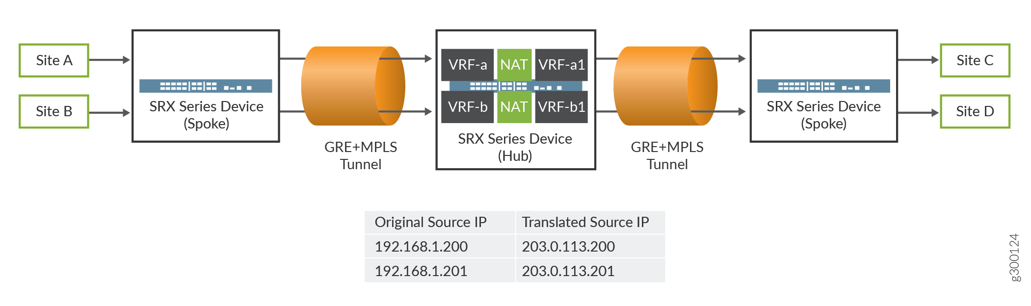
Source NAT is the translation of the source IP address of a packet leaving the Juniper Networks device. Source NAT is used to allow hosts with private IP addresses to access a public network.
In this example, the firewall connects two MPLS private networks to convert the private IP address from one VRF’s private IP address to another VRF’s private IP address. In Figure 1, the spoke firewall is configured with VRF-a and VRF-b routing instances, which are connected to the hub firewall. Site C and site D are connected to another spoke firewall. In the hub firewall, the source IP addresses 192.168.1.200 and 192.168.1.201 from VRF-a and VRF-b routing instances are translated to 203.0.113.200 and 203.0.113.201.
Configuration
Procedure
CLI Quick Configuration
To quickly configure this example, copy the
following commands, paste them into a text file, remove any line breaks,
change any details necessary to match your network configuration,
copy and paste the commands into the CLI at the [edit] hierarchy
level, and then enter commit from configuration mode.
set routing-instances VRF-a instance-type vrf
set routing-instances VRF-a route-distinguisher 30:200
set routing-instances VRF-a vrf-target target:100:100
set routing-instances VRF-a vrf-table-label
set routing-instances VRF-b instance-type vrf
set routing-instances VRF-b route-distinguisher 40:200
set routing-instances VRF-b vrf-target target:200:100
set routing-instances VRF-b vrf-table-label
set routing-instances VRF-a1 instance-type vrf
set routing-instances VRF-a1 route-distinguisher 60:200
set routing-instances VRF-a1 vrf-target target:300:100
set routing-instances VRF-a1 vrf-table-label
set routing-instances VRF-b1 instance-type vrf
set routing-instances VRF-b1 route-distinguisher 50:200
set routing-instances VRF-b1 vrf-target target:400:100
set routing-instances VRF-b1 vrf-table-label
 set security nat source pool vrf-a_p address 203.0.113.200
set security nat source rule-set vrf-a_rs from routing-instance VRF-a
set security nat source rule-set vrf-a_rs to routing-instance VRF-a1
set security nat source rule-set vrf-a_rs rule rule1 match source-address 192.168.1.200
set security nat source rule-set vrf-a_rs rule rule1 then source-nat pool vrf-a_p
set security nat source pool vrf-b_p address 203.0.113.201
set security nat source rule-set vrf-b_rs from routing-instance VRF-b
set security nat source rule-set vrf-b_rs to routing-instance VRF-b1
set security nat source rule-set vrf-b_rs rule rule2 match source-address 192.168.1.201
set security nat source rule-set vrf-b_rs rule rule2 then source-nat pool vrf-b_p
Step-by-Step Procedure
The following example requires you to navigate various levels in the configuration hierarchy.
To configure source NAT mapping:
Layer 3 VPNs require a VRF table for distributing routes within the networks. Create a VRF instance and specify the value vrf.
[edit routing-instances]
user@host#set VRF-a instance-type vrf
user@host#set VRF-b instance-type vrf
user@host#set VRF-a1 instance-type vrf
user@host#set VRF-b1 instance-type vrf
Assign a route distinguisher to the routing instance.
[edit routing-instances]
user@host#set VRF-a route-distinguisher 30:200
user@host#set VRF-b route-distinguisher 40:200
user@host#set VRF-a1 route-distinguisher 60:200
user@host#set VRF-b1 route-distinguisher 50:200
Create a community policy to import or export all routes.
[edit routing-instances]
user@host#set VRF-a vrf-target target:100:100
user@host#set VRF-b vrf-target target:200:100
user@host#set VRF-a1 vrf-target target:300:100
user@host#set VRF-b1 vrf-target target:400:100
Assign a single VPN label for all the routes in the VRF.
[edit routing-instances]
user@host#set VRF-a vrf-table-label
user@host#set VRF-a1 vrf-table-label
user@host#set VRF-b vrf-table-label
user@host#set VRF-b1 vrf-table-label
Create a source NAT pool.
[edit security nat source]
user@host#set vrf-a_p address 203.0.113.200
user@host#set vrf-b_p address 203.0.113.201
Create a source NAT rule set.
[edit security nat source]
user@host#set rule-set vrf-a_rs from routing-instance VRF-a
user@host#set rule-set vrf-a_rs to routing-instance VRF-a1
user@host#set rule-set vrf-b_rs from routing-instance VRF-b
user@host#set rule-set vrf-b_rs to routing-instance VRF-b1
Configure a rule that matches packets and translates the source IP address to an IP address in the source NAT pool.
[edit security nat source]
user@host# set rule-set vrf-a_rs rule rule1 match source-address 192.168.1.200
user@host# set rule-set vrf-a_rs rule rule1 then source-nat pool vrf-a_p
user@host# set rule-set vrf-b_rs rule rule2 match source-address 192.168.1.201
user@host# set rule-set vrf-b_rs rule rule2 then source-nat pool vrf-b_p
Results
From configuration mode, confirm your configuration
by entering the show security nat and show routing-instances commands. If the output does not display the intended configuration,
repeat the configuration instructions in this example to correct it.
[edit]
user@host# show security nat
    source {
        pool vrf-a_p {
            address {
                203.0.113.200/32;
            }
        }
        pool vrf-b_p {
            address {
                203.0.113.201/32;
            }
        }
        rule-set vrf-a_rs {
            from routing-instance VRF-a;
            to routing-instance VRF-a1;
            rule rule1 {
                match {
                    source-address 192.168.1.200/32;
                }
                then {
                    source-nat {
                        pool {
                            vrf-a_p;
                        }
                    }
                }
            }
        }
        rule-set vrf-b_rs {
            from routing-instance VRF-b;
            to routing-instance VRF-b1;
            rule rule2 {
                match {
                    source-address 192.168.1.201/32;
                }
                then {
                    source-nat {
                        pool {
                            vrf-b_p;
                        }
                    }
                }
            }
        }
    }
[edit]
user@host# show routing-instances
    VRF-a {
        instance-type vrf;
        route-distinguisher 30:200;
        vrf-target target:100:100;
        vrf-table-label;
    }
    VRF-a1 {
        instance-type vrf;
        route-distinguisher 60:200;
        vrf-target target:300:100;
        vrf-table-label;
    }
    VRF-b {
        instance-type vrf;
        route-distinguisher 40:200;
        vrf-target target:200:100;
        vrf-table-label;
    }
    VRF-b1 {
        instance-type vrf;
        route-distinguisher 50:200;
        vrf-target target:400:100;
        vrf-table-label;
    }
If you are done configuring the device, enter commit from configuration mode.
Verification
Verifying Source NAT Rule Usage
Purpose
Verify that there is traffic matching the source NAT rule.
Action
From operational mode, enter the show security
nat source rule all command. In the Translation hits field,
verify whether there is traffic that matches the source NAT rule.
user@host>show security nat source rule all
Total rules: 2
Total referenced IPv4/IPv6 ip-prefixes: 2/0
source NAT rule: rule1                  Rule-set: vrf-a_rs
  Rule-Id                    : 1
  Rule position              : 1
  From routing instance      : VRF-a
  To routing instance        : VRF-a1
  Match
    Source addresses         : 192.168.1.200   - 192.168.1.200
  Action                        : vrf-a_p
    Persistent NAT type         : N/A
    Persistent NAT mapping type : address-port-mapping
    Inactivity timeout          : 0
    Max session number          : 0
  Translation hits           : 0
    Successful sessions      : 0
    Failed sessions          : 0
  Number of sessions         : 0
source NAT rule: rule2                  Rule-set: vrf-b_rs
  Rule-Id                    : 2
  Rule position              : 2
  From routing instance      : VRF-b
  To routing instance        : VRF-b1
  Match
    Source addresses         : 192.168.1.201   - 192.168.1.201
  Action                        : vrf-b_p
    Persistent NAT type         : N/A
    Persistent NAT mapping type : address-port-mapping
    Inactivity timeout          : 0
    Max session number          : 0
  Translation hits           : 0
    Successful sessions      : 0
    Failed sessions          : 0
  Number of sessions         : 0
Example: Configuring Destination NAT to Convert Public IP Address to VRF’s Single Private IP Address of a VRF instance
This example describes how to configure the destination NAT mapping of a public IP address to the single VRF’s private address for directing the packets to the correct VRF instance.
Requirements
Understand how firewalls work in an SD-WAN deployment for NAT. See NAT Overview.
Understand Virtual Routing and Forwarding Instances. See Virtual Routing and Forwarding Instances in SD-WAN Deployments.
Overview
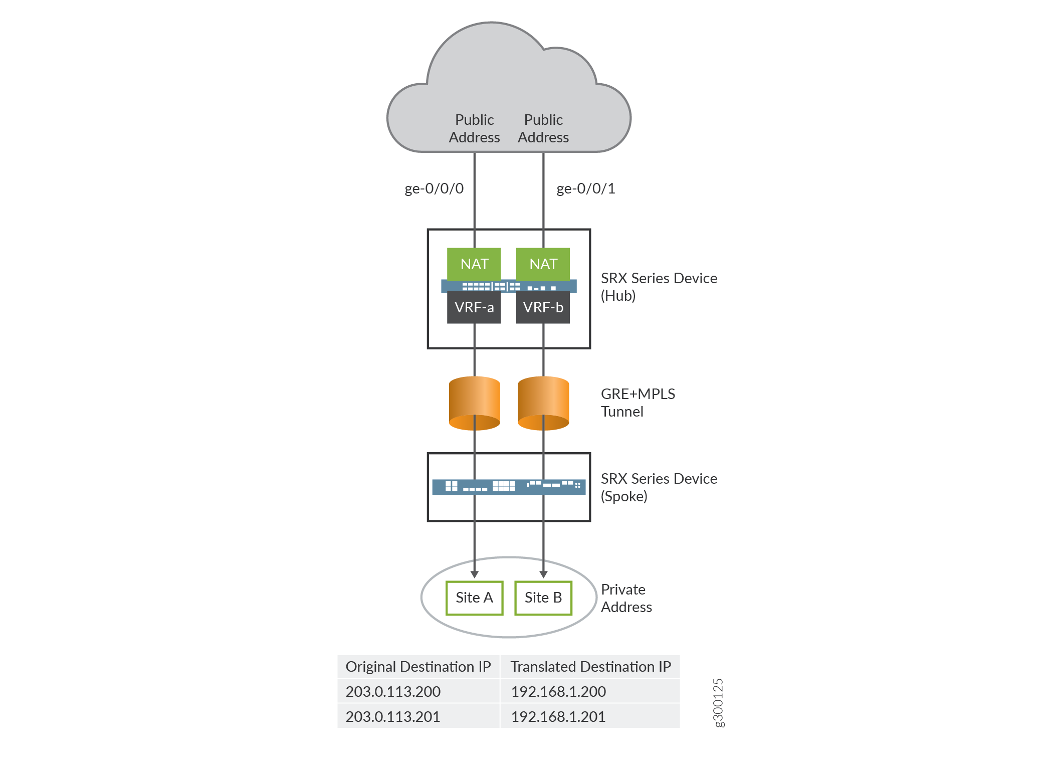
Destination NAT is the translation of the destination IP address of a packet entering the Juniper Networks device. Destination NAT is used to redirect traffic destined to a virtual host (identified by the original destination IP address) to the real host (identified by the translated destination IP address).
In this example, an firewall is configured with destination NAT to convert a public IP address to the VRF private IP address of a VRF instance. The public IP address can be configured per VRF instance. In Figure 2, the firewall is configured with two VRF instances, VRF-a and VRF-b. The firewall coverts the public IP address to private IP address of a VRF instance.
Configuration
Procedure
CLI Quick Configuration
To quickly configure this example, copy the
following commands, paste them into a text file, remove any line breaks,
change any details necessary to match your network configuration,
copy and paste the commands into the CLI at the [edit] hierarchy
level, and then enter commit from configuration mode.
set routing-instances VRF-a instance-type vrf
set routing-instances VRF-a route-distinguisher 30:200
set routing-instances VRF-a vrf-target target:100:100
set routing-instances VRF-a vrf-table-label
set routing-instances VRF-b instance-type vrf
set routing-instances VRF-b route-distinguisher 40:200
set routing-instances VRF-b vrf-target target:200:100
set routing-instances VRF-b vrf-table-label
set security nat destination pool vrf-a_p routing-instance VRF-a
set security nat destination pool vrf-a_p address 192.168.1.200
set security nat destination rule-set rs from interface ge-0/0/0
set security nat destination rule-set rs rule vrf-a_r match destination-address 203.0.113.200
set security nat destination rule-set rs rule vrf-a_r then destination-nat pool vrf-a_p
set security nat destination pool vrf-b_p routing-instance VRF-b
set security nat destination pool vrf-b_p address 192.168.1.201
set security nat destination rule-set rs from interface ge-0/0/1
set security nat destination rule-set rs rule vrf-b_r match destination-address 203.0.113.201
set security nat destination rule-set rs rule vrf-b_r then destination-nat pool vrf-b_p
Step-by-Step Procedure
The following example requires you to navigate various levels in the configuration hierarchy.
To configure destination NAT mapping for a single VRF:
Layer 3 VPNs require a VRF table for distributing routes within the networks. Create a VRF instance and specify the value vrf.
[edit routing-instances]
user@host#set VRF-a instance-type vrf
user@host#set VRF-b instance-type vrf
Assign a route distinguisher to the routing instance.
[edit routing-instances]
user@host#set VRF-a route-distinguisher 30:200
user@host#set VRF-b route-distinguisher 40:200
Create a community policy to import or export all routes.
[edit routing-instances]
user@host#set VRF-a vrf-target target:100:100
user@host#set VRF-b vrf-target target:200:100
Assign a single VPN label for all the routes in the VRF.
[edit routing-instances]
user@host#set VRF-a vrf-table-label
user@host#set VRF-b vrf-table-label
Specify a destination NAT IP address pool.
[edit security nat destination]
user@host# set pool vrf-a_p address 192.168.1.200
user@host# set pool vrf-b_p address 192.168.1.201
Assign the routing instance to the destination pool.
[edit security nat destination]
user@host# set pool vrf-a_p routing-instance VRF-a
user@host# set pool vrf-b_p routing-instance VRF-b
Create a destination NAT rule set.
[edit security nat destination]
user@host# set rule-set rs from interface ge-0/0/0
user@host# set rule-set rs from interface ge-0/0/1
Configure a rule that matches packets and translates the destination IP address to an IP address in the destination NAT IP address pool.
[edit security nat destination]
user@host# set  rule-set rs rule vrf-a_r match destination-address 203.0.113.200
user@host# set rule-set rs rule vrf-a_r then destination-nat pool vrf-a_p
user@host# set rule-set rs rule vrf-b_r match destination-address 203.0.113.201
user@host# set rule-set rs rule vrf-b_r then destination-nat pool vrf-b_p
Results
From configuration mode, confirm your configuration
by entering the show security nat and show routing-instances commands. If the output does not display the intended configuration,
repeat the configuration instructions in this example to correct it.
[edit]
user@host# show security nat
    destination {
        pool vrf-a_p {
            routing-instance {
                VRF-a;
            }
            address 192.168.1.200/32;
        }
        pool vrf-b_p {
            routing-instance {
                VRF-b;
            }
            address 192.168.1.201/32;
        }
        rule-set rs {
            from interface [ ge-0/0/0.0 ge-0/0/1.0 ];
            rule vrf-a_r {
                match {
                    destination-address 203.0.113.200/32;
                }
                then {
                    destination-nat {
                        pool {
                            vrf-a_p;
                        }
                    }
                }
            }
            rule vrf-b_r {
                match {
                    destination-address 203.0.113.201/32;
                }
                then {
                    destination-nat {
                        pool {
                            vrf-b_p;
                        }
                    }
                }
            }
        }
    }
[edit]
user@host# show routing-instances
    VRF-a {
        instance-type vrf;
        route-distinguisher 30:200;
        vrf-target target:100:100;
        vrf-table-label;
    }
    VRF-b {
        instance-type vrf;
        route-distinguisher 40:200;
        vrf-target target:200:100;
        vrf-table-label;
    }
If you are done configuring the device, enter commit from configuration mode.
Verification
Verifying Destination NAT Rule Usage
Purpose
Verify that there is traffic matching the destination NAT rule.
Action
From operational mode, enter the show security
nat destination rule all command. In the Translation hits field,
verify whether there is traffic that matches the destination NAT rule.
user@host> show security nat destination rule all
Total destination-nat rules: 2
Total referenced IPv4/IPv6 ip-prefixes: 2/0
Destination NAT rule: vrf-a_r                Rule-set: rs
  Rule-Id                    : 1
  Rule position              : 1
  From interface             : ge-0/0/0.0
                             : ge-0/0/1.0
    Destination addresses    : 203.0.113.200   - 203.0.113.200
  Action                     : vrf-a_p
  Translation hits           : 0
    Successful sessions      : 0
    Failed sessions          : 0
  Number of sessions         : 0
Destination NAT rule: vrf-b_r                Rule-set: rs
  Rule-Id                    : 2
  Rule position              : 2
  From interface             : ge-0/0/0.0
                             : ge-0/0/1.0
    Destination addresses    : 203.0.113.201   - 203.0.113.201
  Action                     : vrf-b_p
  Translation hits           : 0
    Successful sessions      : 0
    Failed sessions          : 0
  Number of sessions         : 0
Example: Configuring Static NAT to Convert the Private IP Address of a VRF Instance to Public IP Address
This example describes how to configure a static NAT mapping of VRF single private IP address to a public IP address.
Requirements
Understand how firewalls work in an SD-WAN deployment for NAT. See NAT Overview.
Overview
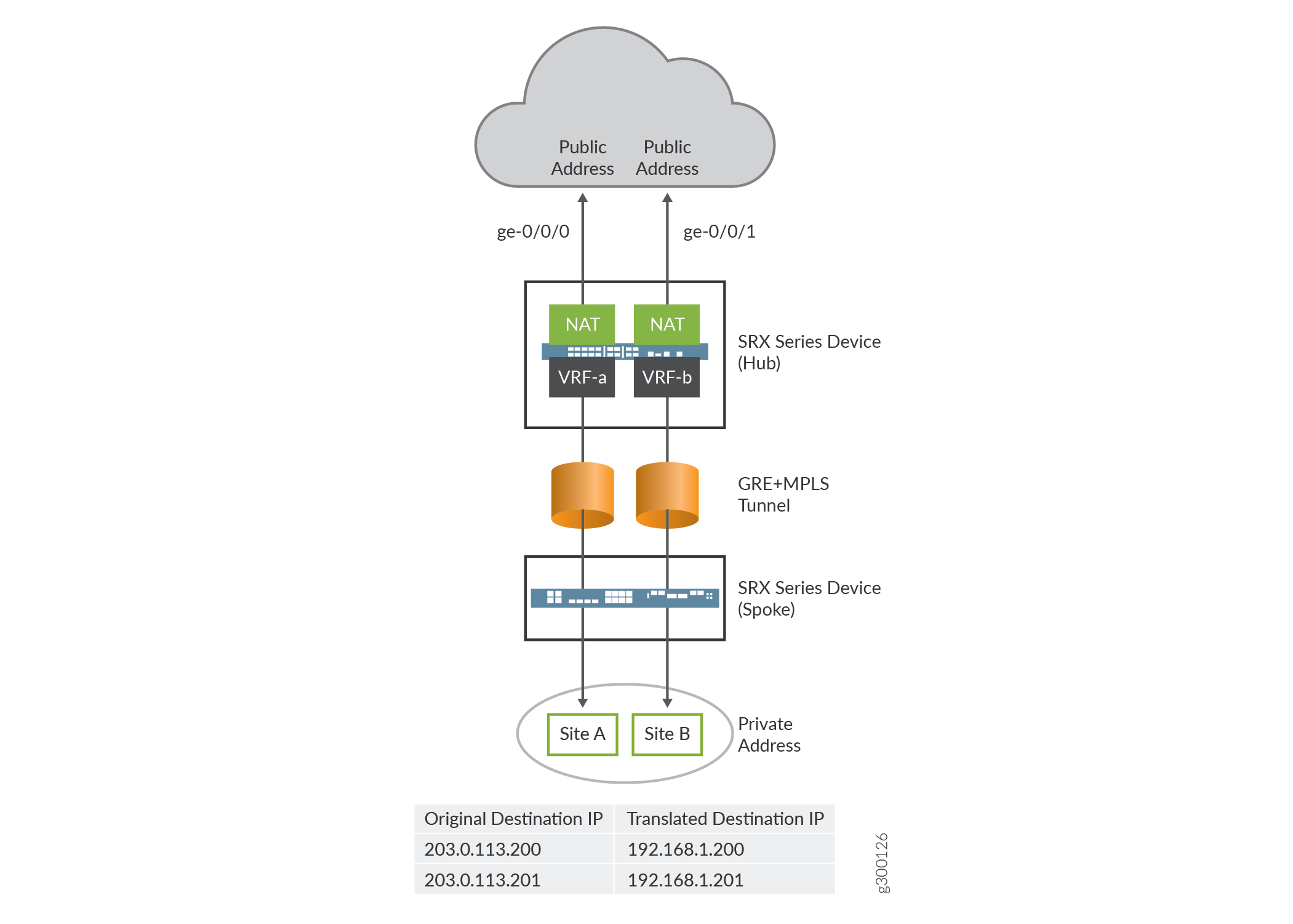
In this example, an firewall is configured with static NAT to convert the VRF private IP address of a VRF instance to a public IP address of a VRF instance. Static NAT can be applied on the source NAT and destination NAT. In Figure 3, the firewall is configured with two VRF instances, VRF-a and VFR-b. The firewall converts the private IP address of a VRF instance to a public IP address.
Configuration
Procedure
CLI Quick Configuration
To quickly configure this example, copy the
following commands, paste them into a text file, remove any line breaks,
change any details necessary to match your network configuration,
copy and paste the commands into the CLI at the [edit] hierarchy
level, and then enter commit from configuration mode.
set routing-instances VRF-a instance-type vrf
set routing-instances VRF-a route-distinguisher 30:200
set routing-instances VRF-a vrf-target target:100:100
set routing-instances VRF-a vrf-table-label
set routing-instances VRF-b instance-type vrf
set routing-instances VRF-b route-distinguisher 40:200
set routing-instances VRF-b vrf-target target:200:100
set routing-instances VRF-b vrf-table-label
set security nat static rule-set rs from interface ge-0/0/0
set security nat static rule-set rs rule vrf-a_r match static-address 203.0.113.200
set security nat static rule-set rs rule vrf-a_r then static-nat prefix 192.168.1.200
set security nat static rule-set rs rule vrf-a_r then static-nat prefix routing-instance VRF-a
set security nat static rule-set rs from interface ge-0/0/1
set security nat static rule-set rs rule vrf-b_r match static-address 203.0.113.201
set security nat static rule-set rs rule vrf-b_r then static-nat prefix 192.168.1.201
set security nat static rule-set rs rule vrf-b_r then static-nat prefix routing-instance VRF-b
Step-by-Step Procedure
The following example requires you to navigate various levels in the configuration hierarchy.
To configure static NAT mapping for the IP address of a single VRF:
Layer 3 VPNs require a VRF table for distributing routes within the networks. Create a VRF instance and specify the value vrf.
[edit routing-instances]
user@host#set VRF-a instance-type vrf
user@host#set VRF-b instance-type vrf
Assign a route distinguisher to the routing instance.
[edit routing-instances]
user@host#set VRF-a route-distinguisher 30:200
user@host#set VRF-b route-distinguisher 40:200
Create a community policy to import or export all routes.
[edit routing-instances]
user@host#set VRF-a vrf-target target:100:100
user@host#set VRF-b vrf-target target:200:100
Assign a single VPN label for all the routes in the VRF.
[edit routing-instances]
user@host#set VRF-a vrf-table-label
user@host#set VRF-b vrf-table-label
Create a static NAT rule set.
[edit security nat static]
user@host# set rule-set rs from interface ge-0/0/0
user@host# set rule-set rs from interface ge-0/0/1
Configure a rule that matches packets and translates the destination address in the packets to a private IP address.
[edit security nat static]
user@host# set rule-set rs rule vrf-a_r match static-address 203.0.113.200
user@host# set rule-set rs rule vrf-a_r then static-nat prefix 192.168.1.200
user@host# set rule-set rs rule vrf-a_r then static-nat prefix routing-instance VRF-a
user@host# set rule-set rs rule vrf-b_r match static-address 203.0.113.201
user@host# set rule-set rs rule vrf-b_r then static-nat prefix 192.168.1.201
user@host# set rule-set rs rule vrf-b_r then static-nat prefix routing-instance VRF-b
Results
From configuration mode, confirm your configuration
by entering the show security nat and show routing-instances commands. If the output does not display the intended configuration,
repeat the configuration instructions in this example to correct it.
[edit]
user@host# show security nat
    static {
        rule-set rs {
            from interface [ ge-0/0/0.0 ge-0/0/1.0 ];
            rule vrf-a_r {
                match {
                    destination-address 203.0.113.200/32;
                }
                then {
                    static-nat {
                        prefix {
                            192.168.1.200/32;
                            routing-instance VRF-a;
                        }
                    }
                }
            }
            rule vrf-b_r {
                match {
                    destination-address 203.0.113.201/32;
                }
                then {
                    static-nat {
                        prefix {
                            192.168.1.201/32;
                            routing-instance VRF-b;
                        }
                    }
                }
            }
        }
    }
[edit]
user@host# show routing-instances
    VRF-a {
        instance-type vrf;
        route-distinguisher 30:200;
        vrf-target target:100:100;
        vrf-table-label;
    }
    VRF-b {
        instance-type vrf;
        route-distinguisher 40:200;
        vrf-target target:200:100;
        vrf-table-label;
    }
If you are done configuring the device, enter commit from configuration mode.
Verification
Verifying Static NAT Rule Usage
Purpose
Verify that there is traffic matching the static NAT rule.
Action
From operational mode, enter the show security
nat static rule command. In the Translation hits field, verify
whether there is traffic that matches the static NAT rule.
user@host> show security nat static rule all
Total static-nat rules: 2
Total referenced IPv4/IPv6 ip-prefixes: 4/0
Static NAT rule: vrf-a_r                Rule-set: rs
  Rule-Id                    : 1
  Rule position              : 1
  From interface             : ge-0/0/0.0
                             : ge-0/0/1.0
  Destination addresses      : 203.0.113.200
  Host addresses             : 192.168.1.200
  Netmask                    : 32
  Host routing-instance      : VRF-a
  Translation hits           : 0
    Successful sessions      : 0
    Failed sessions          : 0
  Number of sessions         : 0
Static NAT rule: vrf-b_r                Rule-set: rs
  Rule-Id                    : 2
  Rule position              : 2
  From interface             : ge-0/0/0.0
                             : ge-0/0/1.0
  Destination addresses      : 203.0.113.201
  Host addresses             : 192.168.1.201
  Netmask                    : 32
  Host routing-instance      : VRF-b
  Translation hits           : 0
    Successful sessions      : 0
    Failed sessions          : 0
  Number of sessions         : 0