Using a Default Layer 3 Gateway to Route Traffic in an EVPN-VXLAN Overlay Network
Physical (bare-metal) servers in an Ethernet VPN-Virtual Extensible LAN (EVPN-VXLAN) environment rely on a default Layer 3 gateway to route their traffic from one virtual network (VN) to another physical server or a virtual machine (VM) in another VN. You can enable the default gateway functionality on a Juniper Networks device that acts as a Layer 3 VXLAN gateway. On a Layer 3 VXLAN gateway, you can configure an integrated routing and bridging (IRB) interface with a virtual gateway address (VGA), which in turn configures the IRB interface as a default Layer 3 gateway. You can configure an IRB interface with a VGA when using EVPN-VXLAN within a data center and across the Data Center Interconnect (DCI) solution.
Understanding the Default Gateway
To enable the default gateway function, you configure an IRB interface with a unique IP address and a media access control (MAC) address. In addition, you configure the IRB interface with a VGA, which must be an anycast IP address, and the Layer 3 VXLAN gateway automatically generates a MAC address.
When you specify an IPv4 address for the VGA, the Layer 3 VXLAN gateway automatically generates 00:00:5e:00:01:01 as the MAC address. When you specify an IPv6 address, the Layer 3 VXLAN gateway automatically generates 00:00:5e:00:02:01 as the MAC address.
On Juniper Networks devices that function as Layer 3 VXLAN gateways, you can
explicitly configure an IPv4 or IPv6 MAC address for a default gateway by using the
virtual-gateway-v4-mac or
virtual-gateway-v6-mac configuration statement at the
[edit interfaces irb unit
                    logical-unit-number]
hierarchy level. With this
configuration, the device overrides the automatically generated MAC address with the
configured MAC address.
A VGA and associated MAC address provide the default gateway function in a particular VN. You configure each host (physical server or VM) in the VN to use the VGA.
By using an anycast IP address as the VGA, when a VM is moved from one EVPN provider edge (PE) device to another in the same VN, the VM can use the same default gateway. In other words, you do not need to update the VM with a new default gateway IP address for MAC binding.
Layer 3 VXLAN gateways in an EVPN-VXLAN topology respond to Address Resolution Protocol (ARP) requests for the VGA and forward packets intended for the default gateway MAC address.
If you assign a VGA to your IRB interfaces, we recommend as a best practice to also configure a virtual gateway MAC (VMAC) address. You should assign the same VMAC to all IRB interfaces that you configure with the same VGA. That is, the VGA address used as the default gateway within a given VN also shares the same VMAC address on all IRB interfaces. The VGA and VMAC combination must be unique within each VN. Stated differently, within a VLAN you assign the same VGA and VMAC while between VNs you must configure unique VGA/VMAC combinations.
| Virtual Network | IRB VGA | IRB VMAC | Note |
|---|---|---|---|
| VN 1 | 10.0.1.254/24 | 00:05:85:00:01:01 | Assign the same VGA and VMAC to all IRBs that service VN 1. These values differ from the ones assigned to the IRB for VN 2. |
| VN 2 | 10.0.2.254/24 | 00:05:85:00:02:02 | Assign the same VGA and VMAC to all IRBs that service VN 2. These values differ from the ones assigned to the IRB for VN 1 |
Following this recommendation avoids an asymmetric data paths for ARP requests and responses when the IRB interface sends ARP messages intended for an end-destination’s MAC address.
On Juniper Networks devices that function as Layer 3 VXLAN gateways in an EVPN-VXLAN centrally-routed bridging overlay (EVPN-VXLAN topology with a two-layer IP fabric), we recommend that the IRB interface IP address is unique across the different Layer 3 VXLAN gateways for a given virtual network, and you configure a virtual gateway MAC address for the IRB. Following this recommendation avoids an asymmetric data path for the ARP request and response when the IRB interface sends ARP messages intended for an end-destination’s MAC address. If you configure a virtual gateway MAC address for the IRB interface, we recommend you use a unique MAC address across the different Layer 3 VXLAN gateways, and in a given Layer 3 VXLAN gateway, use the same MAC address across different IRB units.
For IRB interfaces configured on QFX10000 switches in an EVPN-VXLAN edge-routed bridging overlay (EVPN-VXLAN topology with a two-layer IP fabric), you can alternatively configure each IRB interface on each Layer 3 VXLAN gateway in a VN with the same MAC address. For more information, see Example: Configuring an EVPN-VXLAN Edge-Routed Bridging Fabric with an Anycast Gateway.
Automatic ESI generation is enabled by default on devices in EVPN-VXLAN networks
with EVPN multihoming for virtual gateway redundancy (see Understanding the Redundant Default Gateway). We recommend that you disable the automatic ESI generation
for EVPN networks with edge-routed bridging overlays. To disable automatic ESI
generation, include the no-auto-virtual-gateway-esi statement
at the [edit interfaces irb unit
logical-unit-number] hierarchy level.
To troubleshoot an IRB interface, you can ping the IP address of the interface.
To troubleshoot a default gateway on an MX Series router, you can ping the VGA of
the default gateway from a CE device. To support pinging of the VGA, include the
virtual-gateway-accept-data statement at the [edit
interfaces irb unit] hierarchy of the preferred virtual
gateway.
Additionally, you can ping the IP address of the CE device from the PE device (MX
Series router). To support pinging of the IP address of the CE device, include
the preferred statement at [edit interfaces irb unit
logical-unit-number family (inet |inet6} address
ip-address] hierarchy using the unique IRB
IP address. Otherwise , you must manually specify the unique IRB IP address as
the source IP address when you ping the CE device.
For each IRB interface with a VGA configured, there are two sets of IP and MAC addresses—one set for the IRB interface itself and one set for the default gateway. As a result, the device advertises MAC routes for both IRB interface and default gateway. However, no default gateway extended community attribute is associated with the MAC route advertisement for the default gateway because all Layer 3 VXLAN gateways have the same anycast IP address and MAC binding.
- Understanding How a Default Gateway Handles Known Unicast Traffic Between Virtual Networks
- Understanding How a Default Gateway Handles Unknown Unicast Traffic Between Virtual Networks
Understanding How a Default Gateway Handles Known Unicast Traffic Between Virtual Networks
In the centrally-routed bridging overlay shown in Figure 1, MX Series routers function as Layer 3 VXLAN gateways and QFX5200 switches function as Layer 2 VXLAN gateways. End hosts 1 through 4 are physical servers that must communicate with each other.
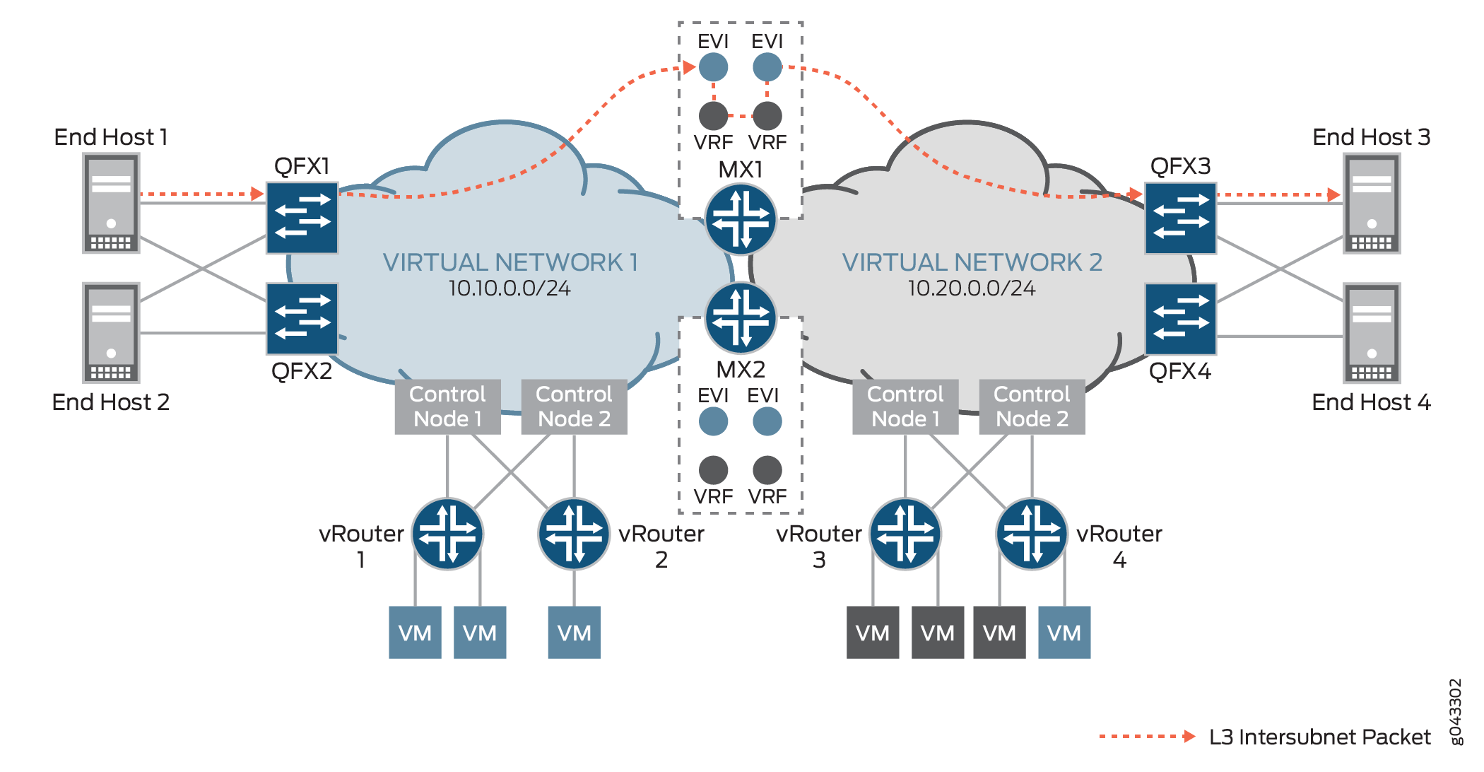
In this topology, end host 1 in VN1 (10.10.0.0/24) and end host 3 in VN 2 (10.20.0.0/24) exchange known unicast packets. Before the exchange of packets between the two end hosts, assume that the hosts sent ARP requests to MX1, which is a Layer 3 VXLAN gateway, and that MX1 responded with the MAC address of a default gateway in VN1.
For example, end host 1 originates a packet and sends it to QFX1, which is a Layer 2 VXLAN gateway. QFX1 encapsulates the packet with a VXLAN header and sends it to MX1. For the inner destination MAC, the packet includes the MAC address of a default gateway in VN1. For the inner destination IP, the packet includes the IP address of end host 3. Upon receipt of the packet, MX1 de-encapsulates it, and after detecting the MAC address of the default gateway in the inner destination MAC field, performs a route lookup for end host 3’s IP address in the L3-VRF routing table for VN1. After a route is found, the packet is routed to VN2 and based on the ARP route entry, the packet is encapsulated with a VXLAN header and sent to QFX3. QFX3 de-encapsulates the packet, and sends it to end host 3.
The traffic flow and handling of known unicast traffic in an edge-routed bridging overlay are essentially the same as described in this section. The only difference is that in the edge-routed bridging overlay, a QFX Series switch that supports Layer 3 VXLAN gateway functionality acts as both Layer 2 and Layer 3 VXLAN gateways.
Understanding How a Default Gateway Handles Unknown Unicast Traffic Between Virtual Networks
The information in this section applies to the traffic flow and handling of unknown unicast packets in both centrally-routed and edge-routed bridging overlays.
For unknown unicast traffic between VNs that is initiated by a physical server, an additional ARP request and response process is required at each stage. After the destination MAC addresses for both default gateway and host is resolved, the traffic flows in the same way as described in Understanding How a Default Gateway Handles Known Unicast Traffic Between Virtual Networks.
Understanding the Redundant Default Gateway
The Juniper Networks devices that function as Layer 3 VXLAN gateways can also provide redundant default gateway functionality. A redundant default gateway prevents the loss of communication between physical servers in one VN and physical servers or VMs in another VN.
The redundant default gateway functionality is typically achieved in an EVPN-VXLAN topology where a provider edge (PE) device such as a Layer 2 VXLAN gateway or a Contrail vRouter is multihomed in active-active mode to multiple Layer 3 VXLAN gateways. On the Layer 3 VXLAN gateways, IRB interfaces are configured as default gateways. Note that each default gateway uses the same VGA and MAC address. In addition, the VGAs and MAC addresses are associated with the same Ethernet segment ID (ESI).
The ESI associated with the VGA and MAC address of the default gateway is automatically derived from an autonomous system (AS) and the VXLAN network identifier (VNI) for the VN. As a result, the default gateway MAC routes advertised by each Layer 3 VXLAN gateway for a given VN have the same ESI.
From the perspective of a Layer 2 VXLAN gateway or a Contrail vRouter that is multihomed to the Layer 3 VXLAN gateways, the addresses of each default gateway configured on each Layer 3 VXLAN gateway is the same. As a result, the PE devices build an equal-cost multipath (ECMP) next hop to reach each default gateway. Traffic that originates from a host and is destined for the MAC address of a default gateway is load balanced.
If one of the Layer 3 VXLAN gateways fails, the remote PE devices are notified of the withdrawing or purging of the next hop to the default gateway MAC address. The path to the failed Layer 3 VXLAN gateway is removed from the next-hop database. Despite the removal of the path, the default gateway that is configured on the remaining Layer 3 VXLAN gateway is still reachable, and the ARP entries for the hosts remain unchanged.
Understanding Dynamic ARP Processing
When a physical server needs to determine the MAC address of its default gateway, the physical server initiates an ARP request that includes the VGA of the default gateway. In a centrally-routed bridging overlay, a Layer 2 VXLAN gateway typically receives the ARP request, encapsulates the request in a VXLAN header, and forwards the encapsulated packet to a Layer 3 VXLAN gateway. In an edge-routed bridging overlay, a Layer 2 and 3 VXLAN gateway typically receives the ARP request from the directly connected physical server.
Upon receipt of the ARP request, the Layer 3 VXLAN gateway de-encapsulates the packet if appropriate, learns the IP and MAC binding of the physical server, and creates an ARP entry in its database. The Layer 3 VXLAN gateway then replies with the MAC address of the default gateway.
In a centrally-routed bridging overlay, the ARP response is encapsulated with a VXLAN header and unicast back to the Layer 2 VXLAN gateway. The Layer 2 VXLAN gateway de-encapsulates the ARP response and forward the packet to the physical server.
In an edge-routed bridging overlay, the ARP response is unicast back to the directly connected physical server.
In a situation where a physical server in VN1 originates a packet that is destined for a physical server in VN2, the Layer 3 VXLAN gateway searches its database for an ARP entry for the destination physical server. If a match is not found, the Layer 3 VXLAN gateway initiates an ARP request that includes the IP and MAC addresses of the IRB interface that is mapped to VN2, and sends the request to the destination physical server. The destination physical server learns the IP/MAC binding of the IRB interface, and adds or refreshes the ARP entry in its database accordingly. The physical server then unicasts an ARP response, which includes the MAC address of the IRB interface, back to the Layer 3 VXLAN gateway,