EVPN-over-VXLAN Supported Functionality
The following functionality is supported for EVPN-over-VXLAN data plane encapsulation:
VXLAN Encapsulation
EVPN supports the VXLAN data plane encapsulation type within the same EVPN instance. To support the VXLAN encapsulation type, all EVPN PE devices specify the tunnel type as VXLAN in the BGP encapsulation extended community. The ingress PE determines which encapsulation types to use based on its own encapsulation capability and the one its EVPN remote PE device advertises.
When EVPN is used as overlay solution for the underlay IP network with VXLAN encapsulation, the data packet is encapsulated with a VXLAN header at the ingress PE device, and the data packet is de-encapsulated from the VXLAN header at the egress PE device. Figure 1 shows the packet format when a packet is forwarded in the core through the underlay IP network with VXLAN encapsulation:

If the underlay network uses the IPv4 protocol and IPv4 addressing, the outer IP header in the VXLAN packet is an IPv4 header. All platforms that support EVPN-VXLAN work with an IPv4 underlay network.
On some platforms, you can configure the underlay to use the IPv6 protocol and IPv6 addressing. In those cases, the outer IP header in the VXLAN packet is an IPv6 header, and you configure the VTEP source address as an IPv6 address. See EVPN-VXLAN with an IPv6 Underlay for details on using an IPv6 underlay.
EVPN BGP Routes and Attributes
EVPN BGP routes and attributes support EVPN-over-VXLAN data plane encapsulation and are affected as follows:
-
By attaching the BGP encapsulation extended community attribute with tunnel encapsulation type VXLAN in the EVPN MAC routes, the egress PE device advertises the EVPN inclusive multicast route and EVPN per EVI route autodiscovery.
-
The Ethernet tag fields for all EVPN BGP routes are set to zero to support VXLAN network identifier (VNI)-based mode only.
-
The VNI, also referred to as the VNI field in the EVPN overlay, is placed in the MPLS fields for the EVPN MAC route, the EVPN inclusive multicast route, and per EVPN instance autodiscovery route.
-
The Ethernet segment identifier label field is set to zero for the EVPN per Ethernet segment autodiscovery route because no Ethernet segment identifier label exists for the supported VXLAN encapsulation type.
-
All corresponding EVPN routes from the remote PE device are resolved over the inet.0 or :vxlan.inet.0 table instead of the inet.3 table for IPv4. When you use an IPv6 underlay for EVPN-VXLAN tunneling, the same is true for the inet6.0 and :vxlan.inet6.0 tables.
EVPN Multihoming Procedure
You can multihome a bare-metal server (BMS) to a pair of Juniper Networks top-of-rack (TOR) switches, for example, QFX5100 switches, through a Layer 2 link aggregation group (LAG) interface. Because of the LAG interface, only one copy of BUM traffic is forwarded from a BMS to the core router. To prevent a Layer 2 loop and flooding of BUM traffic back to the same Ethernet segment to which the multihomed BMS is attached, the BUM traffic applies the multihomed active-active split-horizon filtering rule. To fully support the EVPN multihomed active-active mode feature, the Juniper Networks TOR switch also advertises the EVPN aliasing route to other EVPN PE devices.
The lack of MPLS label support for EVPN over IP with VXLAN data plane encapsulation impacts the following EVPN multihomed active-active mode functions:
EVPN over VXLAN does not support active-standby mode of operation. You can configure only
active-active mode using the all-active option in the ESI
interface configuration. Single-homing Ethernet segments with EVPN using VXLAN
encapsulation with the single-active option is not
supported.
Starting in Junos OS Release 22.2R1, EVPN adds all-active redundancy, aliasing, and mass MAC withdrawal support, including integration of data plane VXLAN, to provide resilient connectivity between data centers to its established Data Center Interconnect (DCI) technologies. This new support builds an end-to-end DCI solution by integrating EVPN multicast with data plane VXLAN.
In an active-active topology, both links are used for load-balancing the traffic. Unicast traffic originating from the EVPN-MPLS domain is load-balanced to both gateways and is forwarded through the VXLAN tunnel to the remote VXLAN end router. Load-balanced packets can come from either of the gateways and cause a MAC flip-flop issue on the VXLAN end router. You can overcome this MAC flip-flop issue by configuring an anycast IP address as a secondary address on the loopback interfaces of the gateways. When you set the anycast address as the vxlan-source-ip, the VXLAN tunnel will be created to the anycast address and the MAC will be learned from the anycast address of the VTEP.
Use the following statements to set active-active redundancy at the ESI level and an anycast address on the lo0 interface. Add a secondary address with an anycast IP to the lo0 interface and include it as the VTEP interface vxlan-source-ip in the routing-instance and the secondary-vtep-address under protocols pim.
set interfaces lo0 unit 0 esi identifier
set interfaces lo0 unit 0 esi all-active
set interfaces lo0 unit 0 family inet address anycast-ip-address
set interfaces lo0 unit 0 family inet address primary-ip-address primary

set protocols pim secondary-vtep-address anycast-ip-address

set routing-instances <name> vtep-source-interface lo0.0
set routing-instances <name> vtep-source-interface inet evpn-mpls-encap vxlan-source-ip anycast-ip-address
Local Bias and Split-Horizon Filtering Rule
Because of the missing MPLS label, the split-horizon filtering rule for the multihomed Ethernet segment is modified and based on the IP address of the EVPN PE device instead of the MPLS Ethernet segment label. For traffic coming from the access interface, any traffic forwarding to the multihomed Ethernet segment is based on the local bias for EVPN with VXLAN data plane encapsulation. Each EVPN PE device tracks the IP address of its peer multihomed EVPN PE device for which it shares the same Ethernet segment. This tracking provides the source VTEP IP address (in the outer IP header) for each VXLAN packet received from the other EVPN PE device. The split-horizon filtering rule is enforced on both ingress and egress PE devices for multi-destination traffic:
-
Ingress PE—Responsible for forwarding multi-destination packets coming from any of its directly-attached access interfaces to its remaining associated multihomed Ethernet segments, regardless of the subject ingress PE device’s designated forwarder (DF) election status.
-
Egress PE—Allows no forwarding of any multi-destination packets to the same multihomed Ethernet segment to which an egress PE shares with its ingress PE device, regardless of the subject egress PE device’s DF election status.
Aliasing
When you connect a BMS to a pair of Juniper Networks TOR switches through a LAG interface bundle, only one of the switches can learn the local MAC address. To support the load balancing of known unicast traffic coming from the VXLAN to the BMS between the switches, the EVPN PE device on the switch must advertise EVPN per EVPN instance autodiscovery route. This advertisement signals to the remote EVPN PE devices that the MAC learned from the multihomed Ethernet segment from its peer multihomed PE device is also reachable. For VXLAN encapsulation, there is no change to the EVPN procedure when providing the EVPN aliasing function.
Next-Hop Forwarding
The Layer 2 address learning daemon (l2ald) creates the VXLAN encapsulation composite next-hop at ingress, and the VXLAN de-encapsulation composite next-hop at the egress. The VXLAN encapsulation composite next-hop forwards Layer 2 unicast traffic to the remote PE device with the VXLAN encapsulation. If multiple paths are available to reach a remote MAC (as with the multihomed EVPN active-active case), the routing protocol daemon (rpd) informs the l2ald of all the remote VTEP IP addresses associated with the remote MAC. The l2ald is responsible for building an equal-cost multipath (ECMP) next hop for the remote MAC. The VXLAN de-encapsulation composite next-hop de-encapsulates the VXLAN tunnel header at the egress and then forwards the traffic to the BMS.
For known unicast traffic:
-
At ingress, the rpd does not need to add a label route in the mpls.0 table.
-
At egress, the rpd does not need to add a label route to point to the table next-hop in the mpls.0 table.
Overlay IRB Loop Prevention
VXLAN tunnel routes are resolved in the underlay. The overlay uses the underlay route resolution for reachability. The underlay, in certain conditions, can use the overlay for reachability, which can lead to routing loops.
Consider a scenario where you configure both VXLAN and an IRB in the same routing
instance, while you also configure the IRB in the OSPF protocol, or via static
routing. You can configure the IRB explicitly by using set protocols ospf
area # interface irb option, or by
using the "interface all" option set protocols ospf area #
interface all. Either approach lets the underlay use the overlay for
tunnel route resolution.
Prevent the underlay from resolving routes using the overlay by configuring the
overlay-vxlan-interfaces statement. Then configure a routing
policy, as shown here:
user@device# set policy-options policy-statement policy-name then install-nexthop except overlay-vxlan-interfaces
user@device# set routing-options forwarding-table export policy-name
Examine the :vxlan.inet.0 table to verify that the system blocks IRB routes. First, review a scenario where the underlay can use overlay routes. The active route uses the IRB:
user@device> show route table :vxlan.inet.0 10.1.1.1/32

:vxlan.inet.0: 15 destinations, 15 routes (15 active, 0 holddown, 0 hidden)
+ = Active Route, - = Last Active, * = Both

10.1.1.1/32         *[Static/1] 00:00:33, metric2 1
                    >  to 10.101.101.11 via irb.1
                       to 10.12.12.1 via et-0/0/2:0.0
This option supports both IPv4 and IPv6. Here is the :vxlan.inet6.0 table with the IRB route:
user@device> show route table :vxlan.inet6.0 abcd::10:1:1:1/128

:vxlan.inet6.0: 10 destinations, 10 routes (10 active, 0 holddown, 0 hidden)
+ = Active Route, - = Last Active, * = Both
abcd::1:1:1:1/128  *[Static/1] 00:30:11, metric2 1
                       to fe80::8ad9:8fff:fe62:b25f via et-0/0/2:0.0
                    >  to fe80::8ad9:8f00:162:b220 via irb.1
Look at the same output when the overlay-vxlan-interfaces statement
prevents the IRB route from being added to the table. Both IPv4 and IPv6 tables are
shown here:
user@device> show route table :vxlan.inet.0 10.1.1.1/32

:vxlan.inet.0: 15 destinations, 15 routes (15 active, 0 holddown, 0 hidden)
+ = Active Route, - = Last Active, * = Both

10.1.1.1/32         *[Static/1] 00:00:15, metric2 1
to 10.12.12.1 via et-0/0/2:0.0user@device> show route table :vxlan.inet6.0 abcd::10:1:1:1/128
:vxlan.inet6.0: 10 destinations, 10 routes (10 active, 0 holddown, 0 hidden)
+ = Active Route, - = Last Active, * = Both
abcd::10:1:1:1/128 *[Static/1] 00:00:16, metric2 1
to fe80::8ad9:8fff:fe62:b25f via et-0/0/2:0.0Control Plane MAC Learning Method
A unique characteristic of EVPN is that MAC address learning between PE devices occurs in the control plane. The local PE router detects a new MAC address from a CE device and then, using MP-BGP, advertises the address to all the remote PE devices. This method differs from existing Layer 2 VPN solutions such as VPLS, which learn by flooding unknown unicast in the data plane. This control plane MAC learning method is a crucial component of the features and benefits that EVPN provides. Because MAC learning is handled in the control plane, EVPN has the flexibility to support different data plane encapsulation technologies between PE devices. This flexibility is important because not every backbone network may be running MPLS, especially in enterprise networks.
For control plane remote MAC learning, because the l2ald creates the VXLAN encapsulation composite next-hop and VXLAN de-encapsulation composite next-hop, the rpd no longer creates an indirect next-hop used in the MAC forwarding table. The rpd relies on the existing mechanism to inform the l2ald of the remote MAC addresses learned from the control plane. Instead of informing the l2ald about the VLAN ID and the indirect next-hop index used by the remote MAC in the MAC FIB table, the rpd informs the l2ald about the remote VTEP IP address and VXLAN network identifier. The control plane remote MAC learned route points to VXLAN encapsulation composite next-hop, or an ECMP next-hop created by the l2ald in the MAC forwarding table.
For multihomed EVPN active-active, a pair of remote VTEP IP addresses are associated with the remote MAC address. The remote VTEP IP addresses are obtained from the MAC route received either from the remote PE device, or from the aliasing route from the remote PE device. When a remote PE device withdraws a MAC route or the aliasing route for the Ethernet segment from where the MAC learned, the rpd alerts the l2ald about the change to the pair of remote VTEP IP addresses accordingly. As a result, the l2ald updates the uni-list next-hop built for this MAC. When both remote MAC routes and its associated aliasing route are withdrawn or become unresolved, the rpd informs the l2ald about the deletion of this remote MAC and the l2ald withdraws this MAC from the MAC forwarding table.
Contrail vRouters and the L3-VRF Table
The Contrail virtualization software creates virtual networks (VNs) associated with routes in a Layer 3 virtual routing and forwarding (L3-VRF) table.
The following are the associated routes:
Subnet Routes for an IRB Interface
For each pair of MAC-(virtual routing and forwarding) VRF and L3-VRF tables created for a virtual network on an MX Series router, a corresponding IRB interface is associated with the MAC-VRF and L3-VRF table pair. The L3-VRF table on the MX Series router has the subnet route from the IRB interface associated with its local virtual networks, as well as, all subnet routes of the IRB interfaces associated with other virtual networks within a data center provided by the Junos OS routing leaking feature. The MX Series routers advertise these subnet routes through MP-BGP to the Contrail control nodes. As a result, the L3-VRF table n the Contrail vRouter contains the same set of subnet routes for the IRB interfaces in its IP FIB, and the subnet routes point their next hops to the MX Series routers.
Virtual Machine Host Routes
The Contrail vRouters support proxy ARP and advertise the IP address with the EVPN MAC route for its virtual machine (VM). For both Contrail vRouters and MX Series routers, the L3-VRF table for a virtual network contains all of the VM host routes for those VMs that reside in the same virtual network, as well as, routes in all other virtual networks. intra- virtual network and inter- virtual network traffic between the VMs is forwarded directly at Layer 3 between the Contrail vRouters.
Bare-Metal Server Host Routes
A Juniper Networks TOR switch, for example, a QFX5100 switch, does not advertise the IP address with the EVPN MAC route for the bare-metal server (BMS) to which it is attached. As a result of the EVPN MAC route advertisement from the switch, no BMS host route is installed in the L3-VRF table on Contrail vRouters and MX Series routers. However, ARP routes for the BMSs are installed in the kernel on the MX Series router if the MX Series router receives ARP responses from the BMSs.
Designated Forwarder Election
To provide better load balance and more flexible topology, the election of the designated forwarder is determined by selecting the minimum VLAN ID or VXLAN network ID for each Ethernet segment instead of selecting based on the EVPN instance. Figure 2 shows a sample designated forwarder election topology.
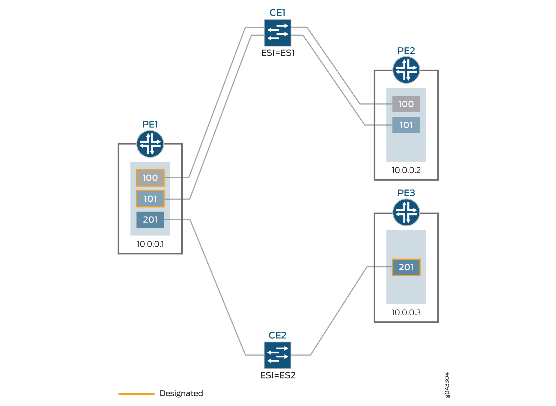
CE device (CE1) has an Ethernet segment identifier value configured equal to ES1 and is connected to both PE1 and PE2 devices, with configured VLANs 100 and 101. Router PE1 is elected as the designated forwarder for the two VLANs.
CE device (CE2) has an Ethernet segment identifier value configured equal to ES2 and is connected to both PE1 and PE3 devices, with configured VLAN 201. Router PE3 is elected as the designated forwarder for this VLAN.
The Ethernet tag ID can be either of the following:
-
VLAN ID (for EVPN-MPLS)
-
VXLAN network ID (for EVPN-VXLAN)