Example: Single MX Series (CSDS Traffic Orchestrator) and Scaled-Out SRX Series Firewall (MNHA) for Stateful Firewall
In this configuration, you'll learn to setup a single MX Series as the CSDS Traffic Orchestrator with SRX Series Firewalls in Multinode High Availability for stateful firewall service.
Connected Security Distributed Services Traffic Orchestrator (CSDS-TO) enables stateless load balancing functionality in MX Series routers. The router distributes the transit traffic across the configured SRX Series Firewalls. CSDS-TO runs a Routing Engine (RE)-based health check process for each SRX Series Firewalls. This process ensures that the traffic management, traffic distribution orchestration, and traffic redirection are connected to the local instance of the network monitoring process.
In this example, CSDS architecture uses MX Series in the forwarding layer to load-balance the traffic and SRX Series Firewalls in the services layer with scaled-out functionality in Multinode High Availability (MNHA) deployment.
SRX Series Firewalls connect in MNHA topology providing stateful session synchronization between the nodes to ensure guaranteed redundancy and an uninterrupted traffic flow. The example demonstrates the configuration of a stateful firewall service with a single MX Series with CSDS-TO and SRX Series Firewalls in MNHA.
|
Reading Time |
Less than two hours |
|
Configuration Time |
Less than three hours |
Example Prerequisites
|
Hardware requirements |
|
|
Software requirements |
|
|
Hardware requirements |
|
|
Software requirements |
|
Ensure you read the following prerequisites:
-
For detailed list of supported platforms and releases, see Release Notes: Connected Security Distributed Services Architecture.
-
Complete the basic setup of MX Series router and SRX Series Firewalls, and ensure the nodes can communicate with each other over the management network.
-
We suggest that you review the Functional Overview, Topology Overview, and Topology Illustration sections to understand the configuration.
-
The example guides you through the step-by-step configuration of MX1 in the forwarding plane, and SRX1-A in the services plane in MNHA mode. You'll find similar set commands for SRX1-B, SRX2-A, and SRX2-B in Appendix 1: Set Commands on SRX1-B, SRX2-A, and SRX2-B Devices. Note that the gateway router is not a device under test (DUT).
-
The example uses MX304 as the gateway router but you can use any device for this role. To provide redundancy in the forwarding layer, consider using a second MX Series router.
-
We recommend that you perform the configuration using Junos Node Unifier (JNU) unified CLI management.
-
You can use Junos OS configuration groups to create reusable groups of configuration statements and apply the groups to multiple levels in the configuration.
Before You Begin
|
Understand CSDS-TO for CSDS |
Understand how CSDS works with the traffic orchestrator. See How Does CSDS Traffic Orchestrator Work |
|
Know more |
|
|
Learn more |
|
Functional Overview
|
Functionality |
Description |
|---|---|
|
FBF of traffic on MX Series |
|
|
Firewall filter on trust side for forward data traffic |
Configure a firewall filter on the
|
|
Firewall filter on untrust side for reverse data traffic |
Configure a firewall filter on the
|
|
CSDS-TO on MX Series |
Deploy forwarding layer functionality on MX Series with CSDS-TO to load-balance the traffic based on the available next hops. MX Series performs RE-based health checks for the available SRX Series Firewalls. The MX Series adds the available SRX Series Firewalls as a composite next-hop in the routing table.
|
|
CSDS-TO for forward data traffic |
Load-balance forward traffic to the available next hop SRX Series
Firewalls server groups based on source-based hashing on the
|
|
CSDS-TO for reverse data traffic |
Load-balance reverse traffic to the available next hop SRX Series
Firewalls server groups based on destination-based hashing on
the
|
|
Functionality |
Description |
|---|---|
|
MNHA pairs |
Based on the traffic load requirements, you can have more MNHA pairs. |
|
MNHA mode |
|
|
Service Redundancy Group (SRG) |
|
|
BGP for routing |
Each of the SRX Series Firewalls have 6 BGP peering sessions with MX1 – 3 for IPv4 data traffic and 3 for IPv6 data traffic.
|
|
Interface |
IP Address |
Description |
|---|---|---|
|
ae10.41 |
|
IPv4 and IPv6 addresses that connect to the GW router on trust side |
|
ae10.81 |
|
IPv4 and IPv6 addresses that connect to the GW router on untrust side |
|
lo0.1 |
|
IPv4 and IPv6 addresses for CSDS-TO health check on
|
|
lo0.2 |
|
IPv4 and IPv6 addresses for CSDS-TO health check on
|
|
ae1.0 |
|
Local IPv4 and IPv6 addresses on |
|
ae1.1 |
|
Local IPv4 and IPv6 addresses on |
|
ae2.0 |
|
Local IPv4 and IPv6 addresses on |
|
ae2.1 |
|
Local IPv4 and IPv6 addresses on |
|
ae3.0 |
|
Local IPv4 and IPv6 addresses on |
|
ae3.1 |
|
Local IPv4 and IPv6 addresses on |
|
ae4.0 |
|
Local IPv4 and IPv6 addresses on |
|
ae4.1 |
|
Local IPv4 and IPv6 addresses on |
|
ae1.100 |
|
Local IP address for BGP peering with SRX1-A in
|
|
ae2.100 |
|
Local IP address for BGP peering with SRX1-B in
|
|
ae3.100 |
|
Local IP address for BGP peering with SRX2-A in
|
|
ae4.100 |
|
Local IP address for BGP peering with SRX2-B in
|
|
Interface |
IP Address |
Description |
|---|---|---|
|
On SRX1-A |
||
|
lo0.0 |
|
MNHA IP address |
|
lo0.1 |
|
Health check IPv4 and IPv6 addresses for MNHA pair 1 |
|
ae1.0 |
|
Local IPv4 and IPv6 addresses for BGP peering with MX1
|
|
ae1.1 |
|
Local IPv4 and IPv6 addresses for BGP peering with MX1 in
|
|
ae1.100 |
10.3.1.2/30 |
Local IP address for BGP peering with MX1 in
|
| On SRX1-B | ||
|
lo0.0 |
|
MNHA IP address |
|
lo0.1 |
|
Health check IPv4 and IPv6 addresses for MNHA pair 1 |
|
ae1.0 |
|
Local IPv4 and IPv6 addresses for BGP peering with MX1
|
|
ae1.1 |
|
Local IPv4 and IPv6 addresses for BGP peering with MX1 in
|
|
ae1.100 |
10.3.2.2/30 |
Local IP address for BGP peering with MX1 in
|
| On SRX2-A | ||
|
lo0.0 |
|
MNHA IP address |
|
lo0.1 |
|
Health check IPv4 and IPv6 addresses for MNHA pair 2 |
|
ae2.0 |
|
Local IPv4 and IPv6 addresses for BGP peering with MX1
|
|
ae2.1 |
|
Local IPv4 and IPv6 addresses for BGP peering with MX1 in
|
|
ae2.100 |
10.3.3.2/30 |
Local IP address for BGP peering with MX1 in
|
| On SRX2-B | ||
|
lo0.0 |
|
MNHA IP address |
|
lo0.1 |
|
Health check IPv4 and IPv6 addresses for MNHA pair 2 |
|
ae2.0 |
|
Local IPv4 and IPv6 addresses for BGP peering with MX1
|
|
ae2.1 |
|
Local IPv4 and IPv6 addresses for BGP peering with MX1 in
|
|
ae2.100 |
10.3.4.2/30 |
Local IP address for BGP peering with MX1 in
|
|
Interface |
IP Address |
Description |
|---|---|---|
|
ae10.41 |
|
Interface that connect to the MX1 on trust side |
|
ae10.81 |
|
Interface that connect to the MX1 on untrust side |
|
et-0/0/2 |
|
Interface on trust side through which the data clients are reachable. |
|
et-0/0/5 |
|
Interface on untrust side through which the Internet server is reachable. |
Topology Overview
|
Device |
Role |
Function |
|---|---|---|
|
MX1 |
Forwarding layer device |
Load-balance traffic using CSDS-TO |
|
SRX1-A |
Services layer device |
Device part of MNHA pair 1 |
|
SRX1-B |
Services layer device |
Device part of MNHA pair 1 |
|
SRX2-A |
Services layer device |
Device part of MNHA pair 2 |
|
SRX2-B |
Services layer device |
Device part of MNHA pair 2 |
|
GW |
Gateway router |
Gateway router for trust side and untrust side networks. The device is used for reaching the data clients and the Internet server. The example uses MX Series. You can use any device. |
|
Feature |
Traffic Flow Component |
IP Address |
|---|---|---|
|
Stateful firewall services on SRX Series Firewalls for Multinode HA Pair 1 (SRX1-A, SRX1-B) |
Source data client |
172.16.160.0/24 |
|
Destination Internet server |
172.16.10.2/32 |
|
|
SRX Series Firewall Series with stateful firewall - Source |
172.16.160.0/24 |
|
|
SRX Series Firewall Series with stateful firewall - Destination |
172.16.10.2/32 |
|
|
Stateful firewall services on SRX Series Firewalls for Multinode HA Pair 2 (SRX2-A, SRX2-B) |
Source data client |
172.16.160.0/24 |
|
Destination Internet server |
172.16.10.2/32 |
|
|
SRX Series Firewall Series with stateful firewall - Source |
172.16.160.0/24 |
|
|
SRX Series Firewall Series with stateful firewall - Destination |
172.16.10.2/32 |
|
Feature |
Traffic Flow Component |
IP Address |
|---|---|---|
|
Stateful firewall services on SRX Series Firewalls for Multinode HA Pair 1 (SRX1-A, SRX1-B) |
Source data client |
2001:db8:172:160::/96 |
|
Destination Internet server |
2001:db8:172:16:10::3/128 |
|
|
SRX Series Firewall with stateful firewall - Source |
2001:db8:172:160::/96 |
|
|
SRX Series Firewall with stateful firewall - Destination |
2001:db8:172:16:10::3/128 |
|
|
Stateful firewall services on SRX Series Firewalls for Multinode HA Pair 2 (SRX2-A, SRX2-B) |
Source data client |
2001:db8:172:160::/96 |
|
Destination Internet server |
2001:db8:172:16:10::3/128 |
|
|
SRX Series Firewall with stateful firewall - Source |
2001:db8:172:160::/96 |
|
|
SRX Series Firewall with stateful firewall - Destination |
2001:db8:172:16:10::3/128 |
Topology Illustration
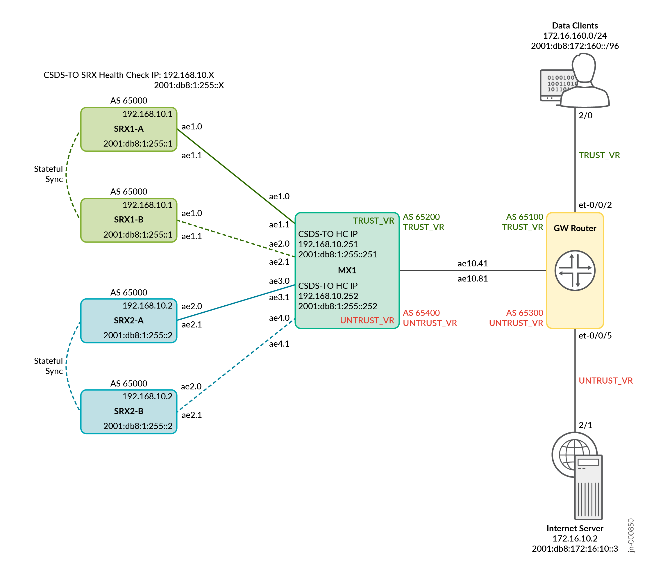
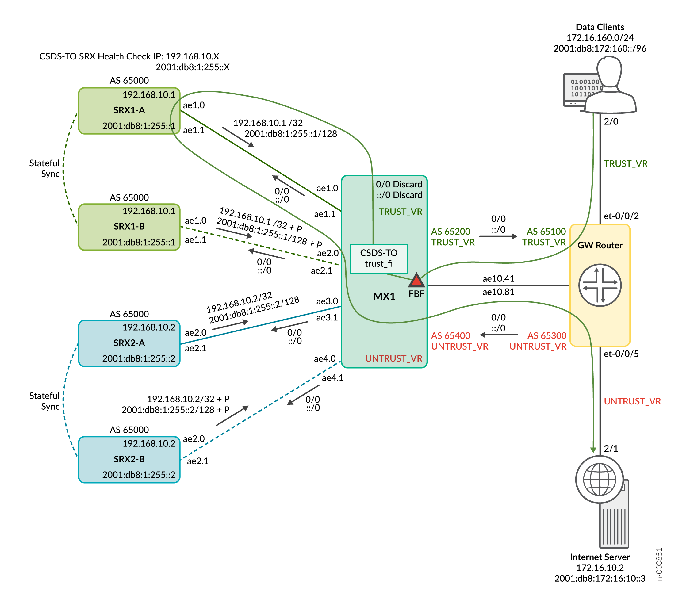
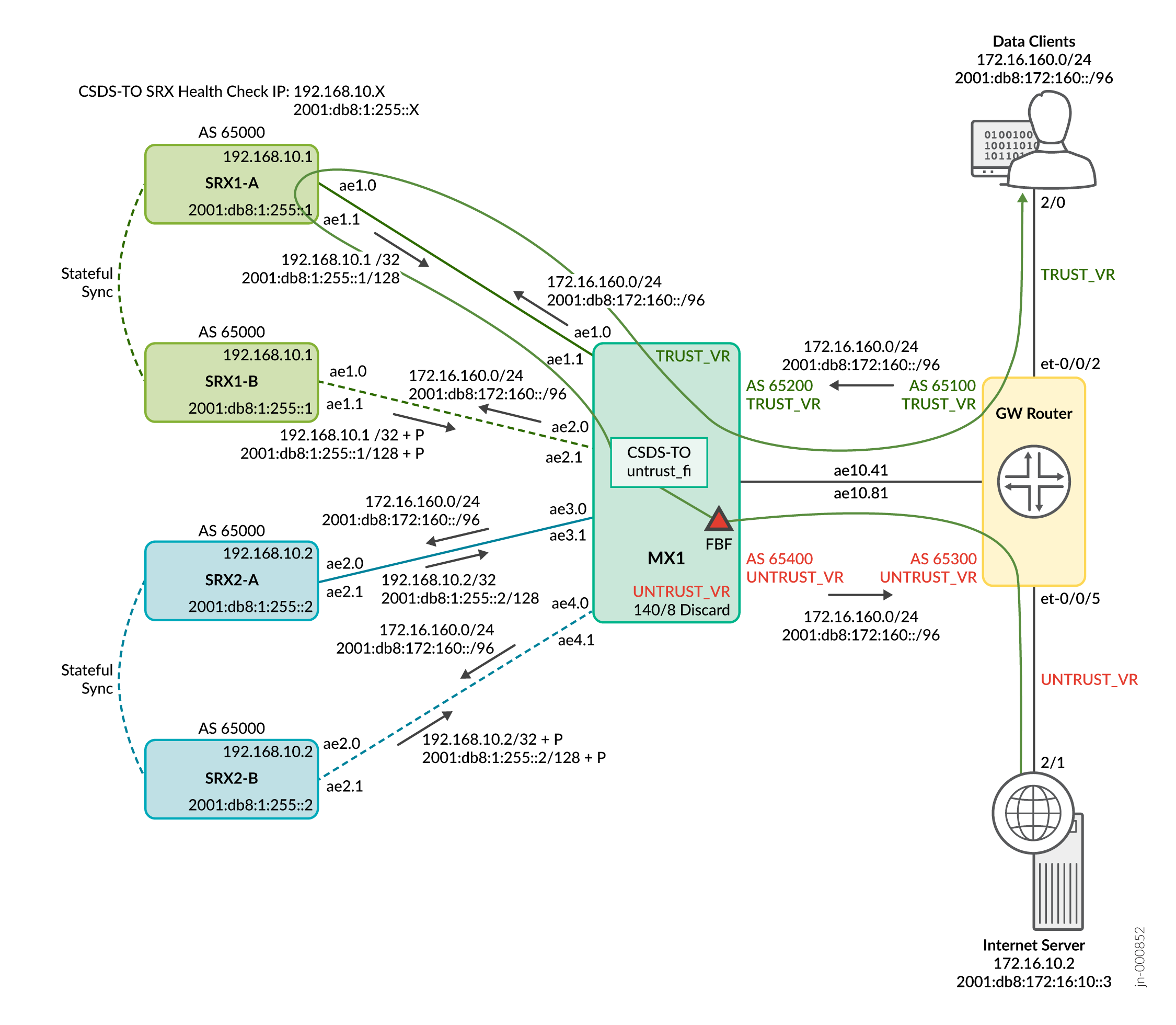
Figure 1 shows that the MX1 performs traffic load balancing based on the available next-hops. The SRX Series Firewalls are the available next-hops. The traffic originating from the data clients is designated as the trusted side traffic. Traffic originating from the Internet is considered as untrust side traffic. The topology uses a GW router that serves as a gateway to the data clients and the Internet server. The devices in the topology use Aggregated Ethernet interfaces. You can use standalone interfaces in your setup.
You'll perform the following tasks in this configuration:
Configure CSDS traffic orchestration on MX1 to load-balance the traffic based on the available next hops.
Configure BGP between MX1 and the firewalls, as well as between MX1 and the GW router. MX1 maintains two routing instances for trust side and untrust side routing.
Configure FBF on trust and untrust sides for forward and reverse traffic.
Configure hashing algorithm-based forwarding decisions for load balancing. Configure two CSDS-TO instances on MX1, one for the trust side and another for the untrust side.
Configure IPv4 and IPv6 based CSDS-TO health checks for the four SRX Series Firewalls available. MX1 performs RE-based health checks on each of the SRX Series Firewalls through CSDS-TO.
Configure the health check IP on the loopback interface. MX1 advertises the loopback interface IP to the firewalls through BGP.
Configure the four SRX Series Firewalls in two MNHA pairs.
In each firewall, configure a server IP which is the MNHA IP address.
In each firewall, configure the health check IP on loopback interface. Both the nodes in a Multinode HA pair use the same health check IP address. Only the primary node responds to the health check request from MX1.
Configure SRG0 for Multinode HA. In the first Multinode HA pair, SRX1-A is the active node and SRX1-B is the standby node. In the second Multinode HA pair, SRX2-A is the active node and SRX2-B is the standby node.
Configure BGP routing for HA communication and stateful synchronization of the sessions. Based on the primary role, the Multinode HA places a single route in the routing table. When the primary role changes, the firewall advertises its routes in BGP.
For the forward data traffic as shown in Figure 2 (Data-clients > GW > MX1 (with FBF on trust side) > SRX > MX1 > GW > Internet server :
-
On the trust side, MX1 advertises a default route to the GW router. The GW router receives the data clients traffic and uses the default route to reach MX1. On untrust side, MX1 receives a default route from the GW router, which then advertises it to the firewalls.
-
The active node in the Multinode HA pair, advertises the health check IP. Always the active node responds to the health checks from MX1. On MX1, the CSDS-TO has two next-hops to the SRX Series Firewalls.
-
When the trust side traffic arrives from GW to MX1, the stateless firewall filter applies FBF on MX1 incoming interface, ae10.41. The trust side FBF filter then matches any source IP from the data clients prefix and sends the traffic to the CSDS-TO forwarding instance, trust-fi.
-
CSDS-TO performs source hash for the data client prefixes. Then, it load balances the traffic over the available active MNHA pair next-hops through interfaces ae1.0 and ae3.0 on MX1. Finally, the traffic reaches the firewalls through interfaces ae1.0 and ae2.0.
-
When the traffic arrives at SRX1-A and SRX2-A, the firewalls create a flow. The packets receive stateful firewall services, and a 5 tuple session gets created for that packets on SRX1-A and SRX2-A.
-
After creating a session for stateful firewall services, the packets exit the firewalls on ae1.1 and ae2.1 interfaces heading to the ae1.1 and ae3.1 interfaces on MX1. MX1 does a route look up and using the default route, the traffic reaches the Internet server
For the reverse data traffic as shown in Figure 3 (Internet server > GW > MX1 (with FBF on untrust side) > SRX > MX1 > GW > Data clients):
-
On the untrust side traffic, traffic coming to the MX1 ae10.81 from the Internet server and destined to the data clients, MX1 applies stateless firewall FBF filter. The untrust side FBF filter, then matches any destination IP from the data clients prefix and sends the traffic to the CSDS-TO forwarding instance, untrust-fi.
-
CSDS-TO performs destination hash for the data client prefixes. Then, it load balances the traffic over the available active MNHA pair next hops through interfaces ae1.1 and ae3.1 on MX1. Finally, the traffic reaches the firewalls through interfaces ae1.1 and ae2.1.
-
In SRX Series Firewalls, the 5 tuple remains the same for the stateful firewall services on both forward flow and reverse flow.
-
On the firewalls the reverse data traffic takes the ae1.0 and ae2.0 on the firewalls and ae1.0 and ae3.0 on MX1.
-
MX1 performs a route look up and traffic goes to the data client.
Step-By-Step Configuration on MX1
Ensure you meet the following prerequisites:
-
Enable commit operation synchronization across both the REs for router with dual REs.
[edit]
user@mx1# set system commit synchronize
-
Enable NETCONF and SSH services for device management.
[edit]
user@mx1# set system services netconf ssh
user@mx1# set system services ssh
-
Ensure SDK service is running using the
show system processes
                                extensive
operational command. Else enable SDK service for CSDS-TO.[edit] user@mx1# set system processes sdk-service enable
Setup MX1 for CSDS-TO configuration.
Run the commands on re0. MX1 ensure synchronization between the REs.
Step-By-Step Configuration on GW Router
Note that GW router configuration is for representational purpose and is not the DUT in the example.
Ensure you've configured the basic settings such as the SSH login services, and chassis configuration.
Setup GW router configuration.
If you have dual RE device, run the commands on re0 and ensure synchronization between the REs.
-
Configure interfaces.
-
Configure routing instances.
-
Configure routing.
-
Configure routing policies for traffic forwarding.
Step-By-Step Configuration on SRX1-A
Ensure you meet the following prerequisites:
-
Enable NETCONF, SSH service, and web management service.
[edit]
user@srx1a# set system services netconf ssh
user@srx1a# set system services ssh
user@srx1a# set system services web-management http port 8088
Setup SRX1-A configuration.
Verification
This section provides a list of show commands that you can use to verify the feature in this example. Run the commands in operational mode.
- CSDS Traffic Orchestration Statistics on MX1
- Verify Routing Details for the Composite Next Hop on MX1
- Verify Routing Details to the Multinode HA Pair from MX1
- Verify Routing Details to the Data Clients from MX1
- Verify Routing Details to the Internet Server from MX1
- Verify MNHA Details on the SRX Series Firewalls
- Verify BGP Session on the SRX Series Firewalls
- Verify Routing Details to the Data Clients from SRX Series Firewalls
- Verify Routing Details to the Internet Server from SRX Series Firewalls
- Verify the Session Flow
CSDS Traffic Orchestration Statistics on MX1
Purpose
Run the command to display the traffic statistics for the load balancing instance.
Action
From operational mode, run the command show services
traffic-load-balance statistics instance
instance-name on MX1.
user@mx1> show services traffic-load-balance statistics instance csds_sfw_trust
Traffic load balance instance name    :  csds_sfw_trust
Network monitor RE daemon connection  :  Established
Route hold timer                      :  180
Active real service count             :  2
Total real service count              :  2

Traffic load balance virtual svc name :  srx_trust_vs
IP address                            :  0.0.0.0
Virtual service mode                  :  Direct Server Return mode
Routing instance name                 :  srx_mnha_group_trust_fi
Traffic load balance group name       :  srx_trust_group
Health check interface subunit        :  1
Demux Nexthop index                   :  N/A (958)
Nexthop index                         :  960
Up time                               :  08:18:39
Total packet sent count               :  13507740880
Total byte sent count                 :  9032043134370
Real service     Address         Sts  Packet Sent  Byte Sent     Packet Recv  Byte Recv
MNHA_SRX1        192.168.10.1    UP   6527869003   4365472577396
MNHA_SRX2        192.168.10.2    UP   6979872383   4666570916733
user@mx1> show services traffic-load-balance statistics instance ipv6_csds_sfw_trust
Traffic load balance instance name    :  ipv6_csds_sfw_trust
Network monitor RE daemon connection  :  Established
Route hold timer                      :  180
Active real service count             :  2
Total real service count              :  2

Traffic load balance virtual svc name :  ipv6_srx_trust_vs
IP address                            :  ::
Virtual service mode                  :  Direct Server Return mode
Routing instance name                 :  srx_mnha_group_trust_fi
Traffic load balance group name       :  ipv6_trust_group
Health check interface subunit        :  1
Demux Nexthop index                   :  N/A (956)
Nexthop index                         :  962
Up time                               :  08:27:27
Total packet sent count               :  13380391037
Total byte sent count                 :  9216175778051
Real service     Address         Sts  Packet Sent  Byte Sent     Packet Recv  Byte Recv
IPv6_MNHA_SRX1   2001:db8:1:255::1 UP 6451076215   4443935999791
IPv6_MNHA_SRX2   2001:db8:1:255::2 UP 6929314019   4772239243054
user@mx1> show services traffic-load-balance statistics instance csds_sfw_untrust
Traffic load balance instance name    :  csds_sfw_untrust
Network monitor RE daemon connection  :  Established
Route hold timer                      :  180
Active real service count             :  2
Total real service count              :  2

Traffic load balance virtual svc name :  srx_untrust_vs
IP address                            :  0.0.0.0
Virtual service mode                  :  Direct Server Return mode
Routing instance name                 :  srx_mnha_group_untrust_fi
Traffic load balance group name       :  srx_untrust_group
Health check interface subunit        :  2
Demux Nexthop index                   :  N/A (959)
Nexthop index                         :  961
Up time                               :  08:18:02
Total packet sent count               :  6031891536
Total byte sent count                 :  4479544730044
Real service     Address         Sts  Packet Sent  Byte Sent     Packet Recv  Byte Recv
UNTRUST_SRX1     192.168.10.1    UP   2916442196   2164710349944
UNTRUST_SRX2     192.168.10.2    UP   3115449728   2314834659940
user@mx1> show services traffic-load-balance statistics instance ipv6_csds_sfw_ut
Traffic load balance instance name    :  ipv6_csds_sfw_ut
Network monitor RE daemon connection  :  Established
Route hold timer                      :  180
Active real service count             :  2
Total real service count              :  2

Traffic load balance virtual svc name :  ipv6_srx_untrust_vs
IP address                            :  ::
Virtual service mode                  :  Direct Server Return mode
Routing instance name                 :  srx_mnha_group_untrust_fi
Traffic load balance group name       :  ipv6_untrust_group
Health check interface subunit        :  2
Demux Nexthop index                   :  N/A (957)
Nexthop index                         :  963
Up time                               :  08:27:26
Total packet sent count               :  5873700154
Total byte sent count                 :  4480319609388
Real service     Address         Sts  Packet Sent  Byte Sent     Packet Recv  Byte Recv
IPv6_UNTRUST_SRX1 2001:db8:1:255::1 UP 2830874180  2158098786836
IPv6_UNTRUST_SRX2 2001:db8:1:255::2 UP 3042825627  2322220543092
Meaning
The command displays the load balancing metrics for IPv4 and IPv6 trust and untrust instances.
Verify Routing Details for the Composite Next Hop on MX1
Purpose
Run the commands to verify the composite next hop when load balancing the traffic using CSDS-TO based on the load and the firewall's availability.
Action
From operational mode, run the command show route table
instance-name on MX1.
user@mx1> show route table srx_mnha_group_trust_fi.inet.0

srx_mnha_group_trust_fi.inet.0: 1 destinations, 1 routes (1 active, 0 holddown, 0 hidden)
+ = Active Route, - = Last Active, * = Both

0.0.0.0/0          *[Static/1] 1d 11:15:11, metric 1
to private composite next hop index 815user@mx1> show route table srx_mnha_group_trust_fi.inet6.0
srx_mnha_group_trust_fi.inet6.0: 2 destinations, 2 routes (2 active, 0 holddown, 0 hidden)
+ = Active Route, - = Last Active, * = Both
::/0 *[Static/1] 1d 11:40:28, metric 1
to private composite next hop index 816user@mx1> show route table srx_mnha_group_untrust_fi.inet.0
srx_mnha_group_untrust_fi.inet.0: 1 destinations, 1 routes (1 active, 0 holddown, 0 hidden)
+ = Active Route, - = Last Active, * = Both
0.0.0.0/0 *[Static/1] 1d 11:15:11, metric 1
to private composite next hop index 814user@mx1> show route table srx_mnha_group_untrust_fi.inet6.0
srx_mnha_group_untrust_fi.inet6.0: 2 destinations, 2 routes (2 active, 0 holddown, 0 hidden)
+ = Active Route, - = Last Active, * = Both
::/0 *[Static/1] 1d 11:39:43, metric 1
to private composite next hop index 817
Meaning
The command displays the routing table for
srx_mnha_group_trust_fi.inet.0,
srx_mnha_group_trust_fi.inet6.0,
srx_mnha_group_untrust_fi.inet.0, and
srx_mnha_group_untrust_fi.inet6.0 instances for the
IPv4 and IPv6 trust side and untrust side traffic.
Verify Routing Details to the Multinode HA Pair from MX1
Purpose
Run the command to verify the routing details to the SRX Series Firewall Series health check IP address.
Action
From operational mode, run the command show routing table
instance-name on MX1.
user@mx1> show route 192.168.10.1/32

TRUST_VR.inet.0: 16 destinations, 18 routes (16 active, 0 holddown, 0 hidden)
+ = Active Route, - = Last Active, * = Both

192.168.10.1/32    *[BGP/170] 03:50:27, localpref 100
                      AS path: 65000 65000 I, validation-state: unverified
                    >  to 10.1.1.2 via ae1.0
                    [BGP/170] 03:48:14, localpref 100
                      AS path: 65000 65000 65000 I, validation-state: unverified
                    >  to 10.1.2.2 via ae2.0

UNTRUST_VR.inet.0: 19 destinations, 25 routes (19 active, 0 holddown, 0 hidden)
+ = Active Route, - = Last Active, * = Both

192.168.10.1/32    *[BGP/170] 03:50:27, localpref 100
                      AS path: 65000 65000 I, validation-state: unverified
                    >  to 10.2.1.2 via ae1.1
                    [BGP/170] 03:48:14, localpref 100
                      AS path: 65000 65000 65000 I, validation-state: unverified
> to 10.2.2.2 via ae2.1user@mx1> show route 192.168.10.2/32
TRUST_VR.inet.0: 16 destinations, 18 routes (16 active, 0 holddown, 0 hidden)
+ = Active Route, - = Last Active, * = Both
192.168.10.2/32 *[BGP/170] 03:58:13, localpref 100
AS path: 65000 65000 I, validation-state: unverified
> to 10.1.3.2 via ae3.0
[BGP/170] 03:58:05, localpref 100
AS path: 65000 65000 65000 I, validation-state: unverified
> to 10.1.4.2 via ae4.0
UNTRUST_VR.inet.0: 19 destinations, 25 routes (19 active, 0 holddown, 0 hidden)
+ = Active Route, - = Last Active, * = Both
192.168.10.2/32 *[BGP/170] 03:58:13, localpref 100
AS path: 65000 65000 I, validation-state: unverified
> to 10.2.3.2 via ae3.1
[BGP/170] 03:58:05, localpref 100
AS path: 65000 65000 65000 I, validation-state: unverified
> to 10.2.4.2 via ae4.1user@mx1> show route 2001:db8:1:255::1/128
TRUST_VR.inet6.0: 23 destinations, 25 routes (23 active, 0 holddown, 0 hidden)
+ = Active Route, - = Last Active, * = Both
2001:db8:1:255::1/128
*[BGP/170] 03:54:56, localpref 100
AS path: 65000 65000 I, validation-state: unverified
> to 2001:db8:1:1:1::2 via ae1.0
[BGP/170] 03:52:43, localpref 100
AS path: 65000 65000 65000 I, validation-state: unverified
> to 2001:db8:1:1:2::2 via ae2.0
UNTRUST_VR.inet6.0: 22 destinations, 24 routes (22 active, 0 holddown, 0 hidden)
+ = Active Route, - = Last Active, * = Both
2001:db8:1:255::1/128
*[BGP/170] 03:54:56, localpref 100
AS path: 65000 65000 I, validation-state: unverified
> to 2001:db8:1:2:1::2 via ae1.1
[BGP/170] 03:52:43, localpref 100
AS path: 65000 65000 65000 I, validation-state: unverified
> to 2001:db8:1:2:2::2 via ae2.1user@mx1> show route 2001:db8:1:255::2/128
TRUST_VR.inet6.0: 23 destinations, 25 routes (23 active, 0 holddown, 0 hidden)
+ = Active Route, - = Last Active, * = Both
2001:db8:1:255::2/128
*[BGP/170] 04:02:28, localpref 100
AS path: 65000 65000 I, validation-state: unverified
> to 2001:db8:1:1:3::2 via ae3.0
[BGP/170] 04:02:20, localpref 100
AS path: 65000 65000 65000 I, validation-state: unverified
> to 2001:db8:1:1:4::2 via ae4.0
UNTRUST_VR.inet6.0: 22 destinations, 24 routes (22 active, 0 holddown, 0 hidden)
+ = Active Route, - = Last Active, * = Both
2001:db8:1:255::2/128
*[BGP/170] 04:02:28, localpref 100
AS path: 65000 65000 I, validation-state: unverified
> to 2001:db8:1:2:3::2 via ae3.1
[BGP/170] 04:02:20, localpref 100
AS path: 65000 65000 65000 I, validation-state: unverified
> to 2001:db8:1:2:4::2 via ae4.1Meaning
The command displays the BGP routing information from MX1 to Multinode HA pairs for IPv4 and IPv6 health check IPs.
Verify Routing Details to the Data Clients from MX1
Purpose
Run the commands to verify the routing details to the data clients through the trust side and untrust side instance for IPv4 and IPv6 data traffic.
Action
From operational mode, run show routing table
instance-name command on MX1.
user@mx1> show route 172.16.10.2 table TRUST_VR.inet

TRUST_VR.inet.0: 16 destinations, 18 routes (16 active, 0 holddown, 0 hidden)
+ = Active Route, - = Last Active, * = Both

0.0.0.0/0          *[Static/5] 23:54:46
Discarduser@mx1> show route 172.16.10.2 table UNTRUST_VR.inet
UNTRUST_VR.inet.0: 19 destinations, 25 routes (19 active, 0 holddown, 0 hidden)
+ = Active Route, - = Last Active, * = Both
0.0.0.0/0 *[BGP/170] 08:32:11, localpref 100
AS path: 65300 I, validation-state: unverified
> to 172.16.2.2 via ae10.81user@mx1> show route 2001:db8:172:160::/96 table TRUST_VR.inet
TRUST_VR.inet6.0: 23 destinations, 25 routes (23 active, 0 holddown, 0 hidden)
+ = Active Route, - = Last Active, * = Both
2001:db8:172:160::/96
*[BGP/170] 08:35:13, localpref 100
AS path: 65100 I, validation-state: unverified
> to 2001:db8:172:1:1::2 via ae10.41user@mx1> show route 2001:db8:172:160::/96 table UNTRUST_VR.inet
UNTRUST_VR.inet6.0: 22 destinations, 24 routes (22 active, 0 holddown, 0 hidden)
+ = Active Route, - = Last Active, * = Both
2001:db8:172:160::/96
*[Static/5] 08:36:31
DiscardMeaning
The command displays the routing details from MX1 trust side and untrust side to the data clients for IPv4 and IPv6 data traffic.
Verify Routing Details to the Internet Server from MX1
Purpose
Run the commands to verify the routing details to the Internet server through the trust side and untrust side instance for IPv4 and IPv6 data traffic.
Action
From operational mode, run show routing table
instance-name command on MX1.
user@mx1> show route 172.16.160.0/24 table TRUST_VR.inet

TRUST_VR.inet.0: 16 destinations, 18 routes (16 active, 0 holddown, 0 hidden)
+ = Active Route, - = Last Active, * = Both

172.16.160.0/24     *[BGP/170] 08:31:10, localpref 100
                      AS path: 65100 I, validation-state: unverified
> to 172.16.1.2 via ae10.41user@mx1> show route 172.16.160.0/24 table UNTRUST_VR.inet
UNTRUST_VR.inet.0: 19 destinations, 25 routes (19 active, 0 holddown, 0 hidden)
+ = Active Route, - = Last Active, * = Both
172.16.160.0/24 *[Static/5] 08:32:14
Discarduser@mx1> show route 2001:db8:172:16:10::3 table TRUST_VR.inet
TRUST_VR.inet6.0: 23 destinations, 25 routes (23 active, 0 holddown, 0 hidden)
+ = Active Route, - = Last Active, * = Both
::/0 *[Static/5] 08:37:11
Discarduser@mx1> show route 2001:db8:172:16:10::3 table UNTRUST_VR.inet
UNTRUST_VR.inet6.0: 22 destinations, 24 routes (22 active, 0 holddown, 0 hidden)
+ = Active Route, - = Last Active, * = Both
::/0 *[BGP/170] 08:36:08, localpref 100
AS path: 65300 I, validation-state: unverified
> to 2001:db8:172:2:1::2 via ae10.81Meaning
The command displays the routing details from MX1 trust side and untrust side to the Internet server for IPv4 and IPv6 data traffic.
Verify MNHA Details on the SRX Series Firewalls
Purpose
Verify the details of the MNHA setup configured on the SRX Series Firewalls.
Action
From operational mode, run show chassis high-availability
information command on the SRX Series Firewalls.
user@srx1a> show chassis high-availability information

Node failure codes:
    HW  Hardware monitoring    LB  Loopback monitoring
    MB  Mbuf monitoring        SP  SPU monitoring
    CS  Cold Sync monitoring   SU  Software Upgrade

Node Status: ONLINE
Local-id: 1
Local-IP: 192.168.0.1
HA Peer Information:

    Peer Id: 2        IP address: 192.168.0.2   Interface: lo0.0
    Routing Instance: MNHA-VR
    Encrypted: NO     Conn State: UP
    Configured BFD Detection Time: 3 * 300ms
    Cold Sync Status: COMPLETE

Services Redundancy Group: 0
        Current State: ONLINE
	Peer Information:
          Peer Id: 2

        Install on Failure Route:
          IP: 192.168.255.0
          Routing Instance: MNHA-VR
Status: NOT INSTALLEDuser@srx1b> show chassis high-availability information
Node failure codes:
HW Hardware monitoring LB Loopback monitoring
MB Mbuf monitoring SP SPU monitoring
CS Cold Sync monitoring SU Software Upgrade
Node Status: ONLINE
Local-id: 2
Local-IP: 192.168.0.2
HA Peer Information:
Peer Id: 1 IP address: 192.168.0.1 Interface: lo0.0
Routing Instance: MNHA-VR
Encrypted: NO Conn State: UP
Configured BFD Detection Time: 3 * 300ms
Cold Sync Status: COMPLETE
Services Redundancy Group: 0
Current State: ONLINE
Peer Information:
Peer Id: 1
Install on Failure Route:
IP: 192.168.255.0
Routing Instance: MNHA-VR
Status: NOT INSTALLEDMeaning
The command displays the local node and peer node details such as the IP address and ID, SRG details on both the nodes in the Multinode HA pair.
Verify BGP Session on the SRX Series Firewalls
Purpose
Verify the summary information about BGP and its neighbors to determine if
routes are received from the peers for the MNHA-VR and
VR-1 routing instances.
Action
From operational mode, run show bgp summary instance
instance-name command on SRX Series
Firewalls.
user@srx1a> show bgp summary instance MNHA-VR

Table          Tot Paths  Act Paths Suppressed    History Damp State    Pending
Peer                     AS      InPkt     OutPkt    OutQ   Flaps Last Up/Dwn State|#Active/Received/Accepted/Damped...
10.3.1.1              65050        140        142       0       1     1:03:35 Establ
  MNHA-VR.inet.0: 2/2/2/0
user@srx1a> show bgp summary instance VR-1

Table          Tot Paths  Act Paths Suppressed    History Damp State    Pending
Peer                     AS      InPkt     OutPkt    OutQ   Flaps Last Up/Dwn State|#Active/Received/Accepted/Damped...
10.1.1.1              65200        141        142       0       1     1:03:46 Establ
  VR-1.inet.0: 3/3/3/0
10.2.1.1              65400        141        143       0       1     1:03:42 Establ
  VR-1.inet.0: 2/2/2/0
2001:db8:1:1:1::1       65200        141        142       0       1     1:03:39 Establ
  VR-1.inet6.0: 3/3/3/0
2001:db8:1:2:1::1       65400        140        142       0       1     1:03:35 Establ
  VR-1.inet6.0: 2/2/2/0
user@srx1b> show bgp summary instance MNHA-VR

Table          Tot Paths  Act Paths Suppressed    History Damp State    Pending
Peer                     AS      InPkt     OutPkt    OutQ   Flaps Last Up/Dwn State|#Active/Received/Accepted/Damped...
10.3.2.1              65050        143        144       0       1     1:04:36 Establ
  MNHA-VR.inet.0: 2/2/2/0
user@srx1b> show bgp summary instance VR-1
Table          Tot Paths  Act Paths Suppressed    History Damp State    Pending
Peer                     AS      InPkt     OutPkt    OutQ   Flaps Last Up/Dwn State|#Active/Received/Accepted/Damped...
10.1.2.1              65200        143        145       0       1     1:04:43 Establ
  VR-1.inet.0: 3/3/3/0
10.2.2.1              65400        143        145       0       1     1:04:43 Establ
  VR-1.inet.0: 2/2/2/0
2001:db8:1:1:2::1       65200        143        144       0       1     1:04:33 Establ
  VR-1.inet6.0: 3/3/3/0
2001:db8:1:2:2::1       65400        143        144       0       1     1:04:32 Establ
  VR-1.inet6.0: 2/2/2/0
Meaning
The command displays that the BGP session is established and the peers
exchange update messages for the MNHA-VR and
VR-1 routing instance on SRX-1A and SRX1-B devices.
Verify Routing Details to the Data Clients from SRX Series Firewalls
Purpose
Run the commands to verify the routing details to the data clients for IPv4 and IPv6 data traffic.
Action
From operational mode, run show routing table
instance-name command on the SRX Series
Firewalls.
user@srx1a> show route table VR-1.inet 172.16.10.2

VR-1.inet.0: 12 destinations, 12 routes (12 active, 0 holddown, 0 hidden)
+ = Active Route, - = Last Active, * = Both

0.0.0.0/0          *[BGP/170] 04:01:38, localpref 100
                      AS path: 65400 65300 I, validation-state: unverified
> to 10.2.1.1 via ae1.1user@srx1a> show route table VR-1.inet 2001:db8:172:160::/96
VR-1.inet6.0: 14 destinations, 14 routes (14 active, 0 holddown, 0 hidden)
+ = Active Route, - = Last Active, * = Both
2001:db8:172:160::/96
*[BGP/170] 04:05:15, localpref 100
AS path: 65200 65100 I, validation-state: unverified
> to 2001:db8:1:1:1::1 via ae1.0user@srx1b> show route table VR-1.inet 172.16.10.2
VR-1.inet.0: 12 destinations, 12 routes (12 active, 0 holddown, 0 hidden)
+ = Active Route, - = Last Active, * = Both
0.0.0.0/0 *[BGP/170] 04:01:47, localpref 100
AS path: 65400 65300 I, validation-state: unverified
> to 10.2.2.1 via ae1.1user@srx1b> show route table VR-1.inet 2001:db8:172:160::/96
VR-1.inet6.0: 14 destinations, 14 routes (14 active, 0 holddown, 0 hidden)
+ = Active Route, - = Last Active, * = Both
2001:db8:172:160::/96
*[BGP/170] 04:05:19, localpref 100
AS path: 65200 65100 I, validation-state: unverified
> to 2001:db8:1:1:2::1 via ae1.0Meaning
The command displays the routing details from SRX1-A and SRX1-B to the data clients for IPv4 and IPv6 data traffic.
Verify Routing Details to the Internet Server from SRX Series Firewalls
Purpose
Run the commands to verify the routing details to the Internet server for IPv4 and IPv6 data traffic.
Action
From operational mode, run show routing table
instance-name command on the SRX Series
Firewalls.
user@srx1a> show route table VR-1.inet 172.16.160.0/24

VR-1.inet.0: 12 destinations, 12 routes (12 active, 0 holddown, 0 hidden)
+ = Active Route, - = Last Active, * = Both

172.16.160.0/24     *[BGP/170] 04:00:52, localpref 100
                      AS path: 65200 65100 I, validation-state: unverified
> to 10.1.1.1 via ae1.0user@srx1a> show route table VR-1.inet 2001:db8:172:16:10::3
VR-1.inet6.0: 14 destinations, 14 routes (14 active, 0 holddown, 0 hidden)
+ = Active Route, - = Last Active, * = Both
::/0 *[BGP/170] 04:05:31, localpref 100
AS path: 65400 65300 I, validation-state: unverified
> to 2001:db8:1:2:1::1 via ae1.1user@srx1b> show route table VR-1.inet 172.16.160.0/24
VR-1.inet.0: 12 destinations, 12 routes (12 active, 0 holddown, 0 hidden)
+ = Active Route, - = Last Active, * = Both
172.16.160.0/24 *[BGP/170] 04:01:04, localpref 100
AS path: 65200 65100 I, validation-state: unverified
> to 10.1.2.1 via ae1.0user@srx1b> show route table VR-1.inet 2001:db8:172:16:10::3
VR-1.inet6.0: 14 destinations, 14 routes (14 active, 0 holddown, 0 hidden)
+ = Active Route, - = Last Active, * = Both
::/0 *[BGP/170] 04:05:36, localpref 100
AS path: 65400 65300 I, validation-state: unverified
> to 2001:db8:1:2:2::1 via ae1.1Meaning
The command displays the routing details from SRX1-A and SRX1-B to the Internet server for IPv4 and IPv6 data traffic.
Verify the Session Flow
Purpose
Run the commands to verify the session flow creation for the stateful firewalls services.
Action
From operational mode, run show security flow session
command on the SRX Series Firewalls.
user@srx1a> show security flow session destination-port 70 source-prefix 172.16.160.0/24

Session ID: 1899887, Policy name: SFW44_POLICY/12, HA State: Active, Timeout: 1794, Session State: Valid
  In: 172.16.160.74/62001 --> 172.16.10.5/70;tcp, Conn Tag: 0x0, If: ae1.0, Pkts: 114392, Bytes: 78341816, HA Wing State: Active,
  Out: 172.16.10.5/70 --> 172.16.160.74/62001;tcp, Conn Tag: 0x0, If: ae1.1, Pkts: 101446, Bytes: 77895248, HA Wing State: Active,
user@srx1a> show security flow session destination-port 70 source-prefix 2001:db8:172:160::/96

Session ID: 1900551, Policy name: SFW66_POLICY/11, HA State: Active, Timeout: 1788, Session State: Valid
  In: 2001:db8:172:160::9/27777 --> 2001:db8:172:16:10::3/70;tcp, Conn Tag: 0x0, If: ae1.0, Pkts: 140045, Bytes: 99153328, HA Wing State: Active,
  Out: 2001:db8:172:16:10::3/70 --> 2001:db8:172:160::9/27777;tcp, Conn Tag: 0x0, If: ae1.1, Pkts: 125352, Bytes: 97972276, HA Wing State: Active,
user@srx1b> show security flow session destination-port 70 source-prefix 172.16.160.0/24

Session ID: 1157000, Policy name: SFW44_POLICY/12, HA State: Warm, Timeout: 1490, Session State: Valid
  In: 172.16.160.74/62001 --> 172.16.10.5/70;tcp, Conn Tag: 0x0, If: ae1.0, Pkts: 0, Bytes: 0, HA Wing State: Warm,
  Out: 172.16.10.5/70 --> 172.16.160.74/62001;tcp, Conn Tag: 0x0, If: ae1.1, Pkts: 0, Bytes: 0, HA Wing State: Warm,
user@srx1b> show security flow session destination-port 70 source-prefix 2001:db8:172:160::/96


Session ID: 1157647, Policy name: SFW66_POLICY/11, HA State: Warm, Timeout: 1642, Session State: Valid
  In: 2001:db8:172:160::9/27777 --> 2001:db8:172:16:10::3/70;tcp, Conn Tag: 0x0, If: ae1.0, Pkts: 0, Bytes: 0, HA Wing State: Warm,
  Out: 2001:db8:172:16:10::3/70 --> 2001:db8:172:160::9/27777;tcp, Conn Tag: 0x0, If: ae1.1, Pkts: 0, Bytes: 0, HA Wing State: Warm,
Meaning
The commands show that the sessions are active on the SRX1-A device.
Appendix 1: Set Commands on SRX1-B, SRX2-A, and SRX2-B Devices
Ensure you meet the following prerequisites on SRX1-B, SRX2-A, and SRX2-B.
-
Enable NETCONF, SSH service, and web management service.
Set commands on all devices.
Set Commands on SRX1-B
set chassis fpc 1 pic 0 port 0 speed 100g
set chassis fpc 1 pic 0 port 1 speed 100g
set chassis fpc 1 pic 0 port 2 speed 100g
set chassis fpc 1 pic 0 port 3 speed 100g
set chassis fpc 1 pic 1 number-of-ports 0

set chassis aggregated-devices ethernet device-count 50
set interfaces et-1/0/2 gigether-options 802.3ad ae1
set interfaces et-1/0/3 gigether-options 802.3ad ae1
set interfaces ae1 vlan-tagging
set interfaces ae1 aggregated-ether-options minimum-links 1
set interfaces ae1 aggregated-ether-options lacp active
set interfaces ae1 aggregated-ether-options lacp periodic fast
set interfaces ae1 unit 0 vlan-id 1
set interfaces ae1 unit 0 family inet address 10.1.2.2/30
set interfaces ae1 unit 0 family inet6 address 2001:db8:1:1:2::2/126
set interfaces ae1 unit 1 vlan-id 2
set interfaces ae1 unit 1 family inet address 10.2.2.2/30
set interfaces ae1 unit 1 family inet6 address 2001:db8:1:2:2::2/126
set interfaces ae1 unit 100 vlan-id 100
set interfaces ae1 unit 100 family inet address 10.3.2.2/30

set interfaces lo0 unit 0 family inet address 192.168.0.2/32 primary
set interfaces lo0 unit 1 family inet address 192.168.10.1/32
set interfaces lo0 unit 1 family inet6 address 2001:db8:1:255::1/128

set chassis high-availability local-id 2 local-ip 192.168.0.2
set chassis high-availability peer-id 1 peer-ip 192.168.0.1
set chassis high-availability peer-id 1 interface lo0.0
set chassis high-availability peer-id 1 routing-instance MNHA-VR
set chassis high-availability peer-id 1 liveness-detection minimum-interval 300
set chassis high-availability peer-id 1 liveness-detection minimum-receive-interval 300
set chassis high-availability peer-id 1 liveness-detection multiplier 3

set chassis high-availability services-redundancy-group 0 peer-id 1
set chassis high-availability services-redundancy-group 0 monitor monitor-object trust object-threshold 300
set chassis high-availability services-redundancy-group 0 monitor monitor-object trust bfd-liveliness threshold 300
set chassis high-availability services-redundancy-group 0 monitor monitor-object trust bfd-liveliness destination-ip 10.1.2.1 src-ip 10.1.2.2

set chassis high-availability services-redundancy-group 0 monitor monitor-object trust bfd-liveliness destination-ip 10.1.2.1 routing-instance VR-1
set chassis high-availability services-redundancy-group 0 monitor monitor-object trust bfd-liveliness destination-ip 10.1.2.1 session-type singlehop
set chassis high-availability services-redundancy-group 0 monitor monitor-object trust bfd-liveliness destination-ip 10.1.2.1 interface ae1.0
set chassis high-availability services-redundancy-group 0 monitor monitor-object trust bfd-liveliness destination-ip 10.1.2.1 weight 300
set chassis high-availability services-redundancy-group 0 monitor srg-threshold 300
set chassis high-availability services-redundancy-group 0 install-on-failure-route 192.168.255.0
set chassis high-availability services-redundancy-group 0 install-on-failure-route routing-instance MNHA-VR

set routing-instances MNHA-VR instance-type virtual-route
set routing-instances MNHA-VR interface ae1.100
set routing-instances MNHA-VR interface lo0.0

set routing-instances VR-1 instance-type virtual-route
set routing-instances VR-1 interface ae1.0
set routing-instances VR-1 interface ae1.1
set routing-instances VR-1 interface lo0.1

set routing-options forwarding-table export lb_policy

set routing-instances MNHA-VR protocols bgp group mnha-ibgp type external
set routing-instances MNHA-VR protocols bgp group mnha-ibgp export mnha_ip
set routing-instances MNHA-VR protocols bgp group mnha-ibgp peer-as 65050
set routing-instances MNHA-VR protocols bgp group mnha-ibgp local-as 65002
set routing-instances MNHA-VR protocols bgp group mnha-ibgp multipath
set routing-instances MNHA-VR protocols bgp group mnha-ibgp bfd-liveness-detection minimum-interval 300
set routing-instances MNHA-VR protocols bgp group mnha-ibgp bfd-liveness-detection minimum-receive-interval 300
set routing-instances MNHA-VR protocols bgp group mnha-ibgp bfd-liveness-detection multiplier 3
set routing-instances MNHA-VR protocols bgp group mnha-ibgp neighbor 10.3.2.1 local-address 10.3.2.2

set routing-instances VR-1 protocols bgp group SRX-to-MX1_TRUST type external
set routing-instances VR-1 protocols bgp group SRX-to-MX1_TRUST export trust_export_policy
set routing-instances VR-1 protocols bgp group SRX-to-MX1_TRUST local-as 65000
set routing-instances VR-1 protocols bgp group SRX-to-MX1_TRUST bfd-liveness-detection minimum-interval 300
set routing-instances VR-1 protocols bgp group SRX-to-MX1_TRUST bfd-liveness-detection minimum-receive-interval 300
set routing-instances VR-1 protocols bgp group SRX-to-MX1_TRUST bfd-liveness-detection multiplier 3
set routing-instances VR-1 protocols bgp group SRX-to-MX1_TRUST neighbor 10.1.2.1 peer-as 65200
set routing-instances VR-1 protocols bgp group SRX-to-MX1_TRUST multipath
set routing-instances VR-1 protocols bgp group IPv6_SRX-to-MX1_TRUST type external
set routing-instances VR-1 protocols bgp group IPv6_SRX-to-MX1_TRUST export ipv6_trust_export_policy
set routing-instances VR-1 protocols bgp group IPv6_SRX-to-MX1_TRUST local-as 65000
set routing-instances VR-1 protocols bgp group IPv6_SRX-to-MX1_TRUST bfd-liveness-detection minimum-interval 300
set routing-instances VR-1 protocols bgp group IPv6_SRX-to-MX1_TRUST bfd-liveness-detection minimum-receive-interval 300
set routing-instances VR-1 protocols bgp group IPv6_SRX-to-MX1_TRUST bfd-liveness-detection multiplier 3
set routing-instances VR-1 protocols bgp group IPv6_SRX-to-MX1_TRUST neighbor 2001:db8:1:1:2::1 peer-as 65200
set routing-instances VR-1 protocols bgp group IPv6_SRX-to-MX1_TRUST multipath

set routing-instances VR-1 protocols bgp group SRX-to-MX1_UNTRUST type external
set routing-instances VR-1 protocols bgp group SRX-to-MX1_UNTRUST export untrust_export_policy
set routing-instances VR-1 protocols bgp group SRX-to-MX1_UNTRUST local-as 65000
set routing-instances VR-1 protocols bgp group SRX-to-MX1_UNTRUST bfd-liveness-detection minimum-interval 300
set routing-instances VR-1 protocols bgp group SRX-to-MX1_UNTRUST bfd-liveness-detection minimum-receive-interval 300
set routing-instances VR-1 protocols bgp group SRX-to-MX1_UNTRUST bfd-liveness-detection multiplier 3
set routing-instances VR-1 protocols bgp group SRX-to-MX1_UNTRUST neighbor 10.2.2.1 peer-as 65400
set routing-instances VR-1 protocols bgp group SRX-to-MX1_UNTRUST multipath
set routing-instances VR-1 protocols bgp group IPv6_SRX-to-MX1_UNTRUST type external
set routing-instances VR-1 protocols bgp group IPv6_SRX-to-MX1_UNTRUST export ipv6_untrust_export_policy
set routing-instances VR-1 protocols bgp group IPv6_SRX-to-MX1_UNTRUST local-as 65000
set routing-instances VR-1 protocols bgp group IPv6_SRX-to-MX1_UNTRUST bfd-liveness-detection minimum-interval 300
set routing-instances VR-1 protocols bgp group IPv6_SRX-to-MX1_UNTRUST bfd-liveness-detection minimum-receive-interval 300
set routing-instances VR-1 protocols bgp group IPv6_SRX-to-MX1_UNTRUST bfd-liveness-detection multiplier 3
set routing-instances VR-1 protocols bgp group IPv6_SRX-to-MX1_UNTRUST neighbor 2001:db8:1:2:2::1 peer-as 65400
set routing-instances VR-1 protocols bgp group IPv6_SRX-to-MX1_UNTRUST multipath

set policy-options policy-statement lb_policy then load-balance per-flow
set policy-options policy-statement trust_export_policy term 1 from protocol direct
set policy-options policy-statement trust_export_policy term 1 from route-filter 192.168.10.1/32 exact
set policy-options policy-statement trust_export_policy term 1 from condition srg_sig_route_exist
set policy-options policy-statement trust_export_policy term 1 then as-path-prepend "65000 65000 65000"
set policy-options policy-statement trust_export_policy term 1 then next-hop self
set policy-options policy-statement trust_export_policy term 1 then accept
set policy-options policy-statement trust_export_policy term 2 from protocol direct
set policy-options policy-statement trust_export_policy term 2 from route-filter 192.168.10.1/32 exact
set policy-options policy-statement trust_export_policy term 2 then as-path-prepend 65000
set policy-options policy-statement trust_export_policy term 2 then next-hop self
set policy-options policy-statement trust_export_policy term 2 then accept
set policy-options policy-statement trust_export_policy term 3 then reject
set policy-options policy-statement trust_export_policy_mx term 1 from protocol bgp
set policy-options policy-statement trust_export_policy_mx term 1 from route-filter 0.0.0.0/0 exact
set policy-options policy-statement trust_export_policy_mx term 1 then next-hop self
set policy-options policy-statement trust_export_policy_mx term 1 then accept
set policy-options policy-statement trust_export_policy_mx term 2 then reject

set policy-options policy-statement ipv6_trust_export_policy term 1 from protocol direct
set policy-options policy-statement ipv6_trust_export_policy term 1 from route-filter 2001:db8:1:255::1/128 exact
set policy-options policy-statement ipv6_trust_export_policy term 1 from condition srg_sig_route_exist
set policy-options policy-statement ipv6_trust_export_policy term 1 then as-path-prepend "65000 65000 65000"
set policy-options policy-statement ipv6_trust_export_policy term 1 then next-hop self
set policy-options policy-statement ipv6_trust_export_policy term 1 then accept
set policy-options policy-statement ipv6_trust_export_policy term 2 from protocol direct
set policy-options policy-statement ipv6_trust_export_policy term 2 from route-filter 2001:db8:1:255::1/128 exact
set policy-options policy-statement ipv6_trust_export_policy term 2 then as-path-prepend 65000
set policy-options policy-statement ipv6_trust_export_policy term 2 then next-hop self
set policy-options policy-statement ipv6_trust_export_policy term 2 then accept
set policy-options policy-statement ipv6_trust_export_policy term 3 then reject
set policy-options policy-statement v6_trust_export_policy term 1 from protocol bgp
set policy-options policy-statement v6_trust_export_policy term 1 from route-filter ::/0 exact
set policy-options policy-statement v6_trust_export_policy term 1 then next-hop self
set policy-options policy-statement v6_trust_export_policy term 1 then accept
set policy-options policy-statement v6_trust_export_policy term 2 then reject

set policy-options policy-statement untrust_export_policy term 1 from protocol direct
set policy-options policy-statement untrust_export_policy term 1 from route-filter 192.168.10.1/32 exact
set policy-options policy-statement untrust_export_policy term 1 from condition srg_sig_route_exist
set policy-options policy-statement untrust_export_policy term 1 then as-path-prepend "65000 65000 65000"
set policy-options policy-statement untrust_export_policy term 1 then next-hop self
set policy-options policy-statement untrust_export_policy term 1 then accept
set policy-options policy-statement untrust_export_policy term 2 from protocol direct
set policy-options policy-statement untrust_export_policy term 2 from route-filter 192.168.10.1/32 exact
set policy-options policy-statement untrust_export_policy term 2 then as-path-prepend 65000
set policy-options policy-statement untrust_export_policy term 2 then next-hop self
set policy-options policy-statement untrust_export_policy term 2 then accept
set policy-options policy-statement untrust_export_policy term 3 then reject
set policy-options policy-statement untrust_export_policy_mx term 1 from protocol bgp
set policy-options policy-statement untrust_export_policy_mx term 1 from route-filter 172.16.80.0/24 orlonger
set policy-options policy-statement untrust_export_policy_mx term 1 from route-filter 172.16.160.0/24 orlonger
set policy-options policy-statement untrust_export_policy_mx term 1 then accept
set policy-options policy-statement untrust_export_policy_mx term 2 then reject

set policy-options policy-statement ipv6_untrust_export_policy term 1 from protocol direct
set policy-options policy-statement ipv6_untrust_export_policy term 1 from route-filter 2001:db8:1:255::1/128 exact
set policy-options policy-statement ipv6_untrust_export_policy term 1 from condition srg_sig_route_exist
set policy-options policy-statement ipv6_untrust_export_policy term 1 then as-path-prepend "65000 65000 65000"
set policy-options policy-statement ipv6_untrust_export_policy term 1 then next-hop self
set policy-options policy-statement ipv6_untrust_export_policy term 1 then accept
set policy-options policy-statement ipv6_untrust_export_policy term 2 from protocol direct
set policy-options policy-statement ipv6_untrust_export_policy term 2 from route-filter 2001:db8:1:255::1/128 exact
set policy-options policy-statement ipv6_untrust_export_policy term 2 then as-path-prepend 65000
set policy-options policy-statement ipv6_untrust_export_policy term 2 then next-hop self
set policy-options policy-statement ipv6_untrust_export_policy term 2 then accept
set policy-options policy-statement ipv6_untrust_export_policy term 3 then reject
set policy-options policy-statement v6_untrust_export_policy term t1 from protocol bgp
set policy-options policy-statement v6_untrust_export_policy term t1 from route-filter 2001:db8:172:160::/96 orlonger
set policy-options policy-statement v6_untrust_export_policy term t1 then next-hop self
set policy-options policy-statement v6_untrust_export_policy term t1 then accept
set policy-options policy-statement v6_untrust_export_policy term t2 then reject

set policy-options policy-statement mnha_ip term 1 from route-filter 192.168.0.1/32 exact
set policy-options policy-statement mnha_ip term 1 then next-hop self
set policy-options policy-statement mnha_ip term 1 then accept
set policy-options policy-statement mnha_ip term 2 then reject
set policy-options policy-statement pfe_lb_hash term ALL-ELSE then load-balance per-flow
set policy-options policy-statement pfe_lb_hash term ALL-ELSE then accept

set policy-options condition srg_sig_route_exist if-route-exists 192.168.255.0/32
set policy-options condition srg_sig_route_exist if-route-exists 192.168.255.0/32 table MNHA-VR.inet.0

set security address-book global address sfw_source_prefix_172.16.80.0/24 172.16.80.0/24
set security address-book global address sfw_source_prefix_172.16.160.0/24 172.16.160.0/24
set security address-book global address sfw_source_prefix_2001:db8:172:160::/96 2001:db8:172:160::/96
set security address-book global address sfw_source_prefix_2001:db8:172:80::/96 2001:db8:172:80::/96

set security zones security-zone VR-1_trust_zone host-inbound-traffic system-services all
set security zones security-zone VR-1_trust_zone host-inbound-traffic protocols all
set security zones security-zone VR-1_trust_zone interfaces ae1.0
set security zones security-zone VR-1_trust_zone interfaces lo0.1
set security zones security-zone VR-1_untrust_zone host-inbound-traffic system-services all
set security zones security-zone VR-1_untrust_zone host-inbound-traffic protocols all
set security zones security-zone VR-1_untrust_zone interfaces ae1.1
set security zones security-zone trust_zone_mnha host-inbound-traffic system-services all
set security zones security-zone trust_zone_mnha host-inbound-traffic protocols all
set security zones security-zone trust_zone_mnha interfaces lo0.0
set security zones security-zone trust_zone_mnha interfaces ae1.100

set security policies from-zone VR-1_trust_zone to-zone VR-1_untrust_zone policy SFW44_POLICY match source-address sfw_source_prefix_172.16.160.0/24
set security policies from-zone VR-1_trust_zone to-zone VR-1_untrust_zone policy SFW44_POLICY match destination-address any
set security policies from-zone VR-1_trust_zone to-zone VR-1_untrust_zone policy SFW44_POLICY match application any
set security policies from-zone VR-1_trust_zone to-zone VR-1_untrust_zone policy SFW44_POLICY then permit
set security policies from-zone VR-1_trust_zone to-zone VR-1_untrust_zone policy SFW66_POLICY match source-address sfw_source_prefix_2001:db8:172:160::/96
set security policies from-zone VR-1_trust_zone to-zone VR-1_untrust_zone policy SFW66_POLICY match destination-address any
set security policies from-zone VR-1_trust_zone to-zone VR-1_untrust_zone policy SFW66_POLICY match application any
set security policies from-zone VR-1_trust_zone to-zone VR-1_untrust_zone policy SFW66_POLICY then permit

set security policies default-policy permit-all
Set Commands on SRX2-A
set chassis fpc 1 pic 0 port 0 speed 100g
set chassis fpc 1 pic 0 port 1 speed 100g
set chassis fpc 1 pic 0 port 2 speed 100g
set chassis fpc 1 pic 0 port 3 speed 100g
set chassis fpc 1 pic 1 number-of-ports 0

set chassis aggregated-devices ethernet device-count 50
set interfaces et-1/0/0 gigether-options 802.3ad ae2
set interfaces et-1/0/1 gigether-options 802.3ad ae2
set interfaces ae2 vlan-tagging
set interfaces ae2 aggregated-ether-options minimum-links 1
set interfaces ae2 aggregated-ether-options lacp active
set interfaces ae2 aggregated-ether-options lacp periodic fast
set interfaces ae2 unit 0 vlan-id 1
set interfaces ae2 unit 0 family inet address 10.1.3.2/30
set interfaces ae2 unit 0 family inet6 address 2001:db8:1:1:3::2/126
set interfaces ae2 unit 1 vlan-id 2
set interfaces ae2 unit 1 family inet address 10.2.3.2/30
set interfaces ae2 unit 1 family inet6 address 2001:db8:1:2:3::2/126
set interfaces ae2 unit 100 vlan-id 100
set interfaces ae2 unit 100 family inet address 10.3.3.2/30

set interfaces lo0 unit 0 family inet address 192.168.0.3/32 primary
set interfaces lo0 unit 1 family inet address 192.168.10.2/32
set interfaces lo0 unit 1 family inet6 address 2001:db8:1:255::2/128

set chassis high-availability local-id 1 local-ip 192.168.0.3
set chassis high-availability peer-id 2 peer-ip 192.168.0.4
set chassis high-availability peer-id 2 interface lo0.0
set chassis high-availability peer-id 2 routing-instance MNHA-VR
set chassis high-availability peer-id 2 liveness-detection minimum-interval 300
set chassis high-availability peer-id 2 liveness-detection minimum-receive-interval 300
set chassis high-availability peer-id 2 liveness-detection multiplier 3

set chassis high-availability services-redundancy-group 0 peer-id 2
set chassis high-availability services-redundancy-group 0 monitor monitor-object trust object-threshold 300
set chassis high-availability services-redundancy-group 0 monitor monitor-object trust bfd-liveliness threshold 300
set chassis high-availability services-redundancy-group 0 monitor monitor-object trust bfd-liveliness destination-ip 10.1.3.1 src-ip 10.1.3.2
set chassis high-availability services-redundancy-group 0 monitor monitor-object trust bfd-liveliness destination-ip 10.1.3.1 routing-instance VR-1
set chassis high-availability services-redundancy-group 0 monitor monitor-object trust bfd-liveliness destination-ip 10.1.3.1 session-type singlehop
set chassis high-availability services-redundancy-group 0 monitor monitor-object trust bfd-liveliness destination-ip 10.1.3.1 interface ae2.0
set chassis high-availability services-redundancy-group 0 monitor monitor-object trust bfd-liveliness destination-ip 10.1.3.1 weight 300
set chassis high-availability services-redundancy-group 0 monitor srg-threshold 300
set chassis high-availability services-redundancy-group 0 install-on-failure-route 192.168.255.0
set chassis high-availability services-redundancy-group 0 install-on-failure-route routing-instance MNHA-VR

set routing-instances MNHA-VR instance-type virtual-route
set routing-instances MNHA-VR interface ae2.100
set routing-instances MNHA-VR interface lo0.0

set routing-instances VR-1 instance-type virtual-route
set routing-instances VR-1 interface ae2.0
set routing-instances VR-1 interface ae2.1
set routing-instances VR-1 interface lo0.1

 set routing-options forwarding-table export lb_policy

set routing-instances MNHA-VR protocols bgp group mnha-ibgp type external
set routing-instances MNHA-VR protocols bgp group mnha-ibgp export mnha_ip
set routing-instances MNHA-VR protocols bgp group mnha-ibgp peer-as 65050
set routing-instances MNHA-VR protocols bgp group mnha-ibgp local-as 65001
set routing-instances MNHA-VR protocols bgp group mnha-ibgp multipath
set routing-instances MNHA-VR protocols bgp group mnha-ibgp bfd-liveness-detection minimum-interval 300
set routing-instances MNHA-VR protocols bgp group mnha-ibgp bfd-liveness-detection minimum-receive-interval 300
set routing-instances MNHA-VR protocols bgp group mnha-ibgp bfd-liveness-detection multiplier 3
set routing-instances MNHA-VR protocols bgp group mnha-ibgp neighbor 10.3.3.1 local-address 10.3.3.2

set routing-instances VR-1 protocols bgp group SRX-to-MX1_TRUST type external
set routing-instances VR-1 protocols bgp group SRX-to-MX1_TRUST export trust_export_policy
set routing-instances VR-1 protocols bgp group SRX-to-MX1_TRUST local-as 65000
set routing-instances VR-1 protocols bgp group SRX-to-MX1_TRUST bfd-liveness-detection minimum-interval 300
set routing-instances VR-1 protocols bgp group SRX-to-MX1_TRUST bfd-liveness-detection minimum-receive-interval 300
set routing-instances VR-1 protocols bgp group SRX-to-MX1_TRUST bfd-liveness-detection multiplier 3
set routing-instances VR-1 protocols bgp group SRX-to-MX1_TRUST neighbor 10.1.3.1 peer-as 65200
set routing-instances VR-1 protocols bgp group SRX-to-MX1_TRUST multipath
set routing-instances VR-1 protocols bgp group IPv6_SRX-to-MX1_TRUST type external
set routing-instances VR-1 protocols bgp group IPv6_SRX-to-MX1_TRUST export ipv6_trust_export_policy
set routing-instances VR-1 protocols bgp group IPv6_SRX-to-MX1_TRUST local-as 65000
set routing-instances VR-1 protocols bgp group IPv6_SRX-to-MX1_TRUST bfd-liveness-detection minimum-interval 300
set routing-instances VR-1 protocols bgp group IPv6_SRX-to-MX1_TRUST bfd-liveness-detection minimum-receive-interval 300
set routing-instances VR-1 protocols bgp group IPv6_SRX-to-MX1_TRUST bfd-liveness-detection multiplier 3
set routing-instances VR-1 protocols bgp group IPv6_SRX-to-MX1_TRUST neighbor 2001:db8:1:1:3::1 peer-as 65200
set routing-instances VR-1 protocols bgp group IPv6_SRX-to-MX1_TRUST multipath

set routing-instances VR-1 protocols bgp group SRX-to-MX1_UNTRUST type external
set routing-instances VR-1 protocols bgp group SRX-to-MX1_UNTRUST export untrust_export_policy
set routing-instances VR-1 protocols bgp group SRX-to-MX1_UNTRUST local-as 65000
set routing-instances VR-1 protocols bgp group SRX-to-MX1_UNTRUST bfd-liveness-detection minimum-interval 300
set routing-instances VR-1 protocols bgp group SRX-to-MX1_UNTRUST bfd-liveness-detection minimum-receive-interval 300
set routing-instances VR-1 protocols bgp group SRX-to-MX1_UNTRUST bfd-liveness-detection multiplier 3
set routing-instances VR-1 protocols bgp group SRX-to-MX1_UNTRUST neighbor 10.2.3.1 peer-as 65400
set routing-instances VR-1 protocols bgp group SRX-to-MX1_UNTRUST multipath
set routing-instances VR-1 protocols bgp group IPv6_SRX-to-MX1_UNTRUST type external
set routing-instances VR-1 protocols bgp group IPv6_SRX-to-MX1_UNTRUST export ipv6_untrust_export_policy
set routing-instances VR-1 protocols bgp group IPv6_SRX-to-MX1_UNTRUST local-as 65000
set routing-instances VR-1 protocols bgp group IPv6_SRX-to-MX1_UNTRUST bfd-liveness-detection minimum-interval 300
set routing-instances VR-1 protocols bgp group IPv6_SRX-to-MX1_UNTRUST bfd-liveness-detection minimum-receive-interval 300
set routing-instances VR-1 protocols bgp group IPv6_SRX-to-MX1_UNTRUST bfd-liveness-detection multiplier 3
set routing-instances VR-1 protocols bgp group IPv6_SRX-to-MX1_UNTRUST neighbor 2001:db8:1:2:3::1 peer-as 65400
set routing-instances VR-1 protocols bgp group IPv6_SRX-to-MX1_UNTRUST multipath

set policy-options policy-statement lb_policy then load-balance per-flow

set policy-options policy-statement trust_export_policy term 1 from protocol direct
set policy-options policy-statement trust_export_policy term 1 from route-filter 192.168.10.1/32 exact
set policy-options policy-statement trust_export_policy term 1 from condition srg_sig_route_exist
set policy-options policy-statement trust_export_policy term 1 then as-path-prepend "65000 65000 65000"
set policy-options policy-statement trust_export_policy term 1 then next-hop self
set policy-options policy-statement trust_export_policy term 1 then accept
set policy-options policy-statement trust_export_policy term 2 from protocol direct
set policy-options policy-statement trust_export_policy term 2 from route-filter 192.168.10.2/32 exact
set policy-options policy-statement trust_export_policy term 2 then as-path-prepend 65000
set policy-options policy-statement trust_export_policy term 2 then next-hop self
set policy-options policy-statement trust_export_policy term 2 then accept
set policy-options policy-statement trust_export_policy term 3 then reject
set policy-options policy-statement trust_export_policy_mx term 1 from protocol bgp
set policy-options policy-statement trust_export_policy_mx term 1 from route-filter 0.0.0.0/0 exact
set policy-options policy-statement trust_export_policy_mx term 1 then next-hop self
set policy-options policy-statement trust_export_policy_mx term 1 then accept
set policy-options policy-statement trust_export_policy_mx term 2 then reject

set policy-options policy-statement ipv6_trust_export_policy term 1 from protocol direct
set policy-options policy-statement ipv6_trust_export_policy term 1 from route-filter 2001:db8:1:255::2/128 exact
set policy-options policy-statement ipv6_trust_export_policy term 1 from condition srg_sig_route_exist
set policy-options policy-statement ipv6_trust_export_policy term 1 then as-path-prepend "65000 65000 65000"
set policy-options policy-statement ipv6_trust_export_policy term 1 then next-hop self
set policy-options policy-statement ipv6_trust_export_policy term 1 then accept
set policy-options policy-statement ipv6_trust_export_policy term 2 from protocol direct
set policy-options policy-statement ipv6_trust_export_policy term 2 from route-filter 2001:db8:1:255::2/128 exact
set policy-options policy-statement ipv6_trust_export_policy term 2 then as-path-prepend 65000
set policy-options policy-statement ipv6_trust_export_policy term 2 then next-hop self
set policy-options policy-statement ipv6_trust_export_policy term 2 then accept
set policy-options policy-statement ipv6_trust_export_policy term 3 then reject
set policy-options policy-statement v6_trust_export_policy term 1 from protocol bgp
set policy-options policy-statement v6_trust_export_policy term 1 from route-filter ::/0 exact
set policy-options policy-statement v6_trust_export_policy term 1 then next-hop self
set policy-options policy-statement v6_trust_export_policy term 1 then accept
set policy-options policy-statement v6_trust_export_policy term 2 then reject

set policy-options policy-statement untrust_export_policy term 1 from protocol direct
set policy-options policy-statement untrust_export_policy term 1 from route-filter 192.168.10.2/32 exact
set policy-options policy-statement untrust_export_policy term 1 from condition srg_sig_route_exist
set policy-options policy-statement untrust_export_policy term 1 then as-path-prepend "65000 65000 65000"
set policy-options policy-statement untrust_export_policy term 1 then next-hop self
set policy-options policy-statement untrust_export_policy term 1 then accept
set policy-options policy-statement untrust_export_policy term 2 from protocol direct
set policy-options policy-statement untrust_export_policy term 2 from route-filter 192.168.10.2/32 exact
set policy-options policy-statement untrust_export_policy term 2 then as-path-prepend 65000
set policy-options policy-statement untrust_export_policy term 2 then next-hop self
set policy-options policy-statement untrust_export_policy term 2 then accept
set policy-options policy-statement untrust_export_policy term 3 then reject
set policy-options policy-statement untrust_export_policy_mx term 1 from protocol bgp
set policy-options policy-statement untrust_export_policy_mx term 1 from route-filter 172.16.80.0/24 orlonger
set policy-options policy-statement untrust_export_policy_mx term 1 from route-filter 172.16.160.0/24 orlonger
set policy-options policy-statement untrust_export_policy_mx term 1 then accept
set policy-options policy-statement untrust_export_policy_mx term 2 then reject

set policy-options policy-statement ipv6_untrust_export_policy term 1 from protocol direct
set policy-options policy-statement ipv6_untrust_export_policy term 1 from route-filter 2001:db8:1:255::2/128 exact
set policy-options policy-statement ipv6_untrust_export_policy term 1 from condition srg_sig_route_exist
set policy-options policy-statement ipv6_untrust_export_policy term 1 then as-path-prepend "65000 65000 65000"
set policy-options policy-statement ipv6_untrust_export_policy term 1 then next-hop self
set policy-options policy-statement ipv6_untrust_export_policy term 1 then accept
set policy-options policy-statement ipv6_untrust_export_policy term 2 from protocol direct
set policy-options policy-statement ipv6_untrust_export_policy term 2 from route-filter 2001:db8:1:255::2/128 exact
set policy-options policy-statement ipv6_untrust_export_policy term 2 then as-path-prepend 65000
set policy-options policy-statement ipv6_untrust_export_policy term 2 then next-hop self
set policy-options policy-statement ipv6_untrust_export_policy term 2 then accept
set policy-options policy-statement ipv6_untrust_export_policy term 3 then reject
set policy-options policy-statement v6_untrust_export_policy term t1 from protocol bgp
set policy-options policy-statement v6_untrust_export_policy term t1 from route-filter 2001:db8:172:160::/96 orlonger
set policy-options policy-statement v6_untrust_export_policy term t1 then next-hop self
set policy-options policy-statement v6_untrust_export_policy term t1 then accept
set policy-options policy-statement v6_untrust_export_policy term t2 then reject

set policy-options policy-statement mnha_ip term 1 from route-filter 192.168.0.3/32 exact
set policy-options policy-statement mnha_ip term 1 then next-hop self
set policy-options policy-statement mnha_ip term 1 then accept
set policy-options policy-statement mnha_ip term 2 then reject
set policy-options policy-statement pfe_lb_hash term ALL-ELSE then load-balance per-flow
set policy-options policy-statement pfe_lb_hash term ALL-ELSE then accept

set policy-options condition srg_sig_route_exist if-route-exists 192.168.255.0/32
set policy-options condition srg_sig_route_exist if-route-exists 192.168.255.0/32 table MNHA-VR.inet.0

set security address-book global address sfw_source_prefix_172.16.80.0/24 172.16.80.0/24
set security address-book global address sfw_source_prefix_172.16.160.0/24 172.16.160.0/24
set security address-book global address sfw_source_prefix_2001:db8:172:160::/96 2001:db8:172:160::/96
set security address-book global address sfw_source_prefix_2001:db8:172:80::/96 2001:db8:172:80::/96

set security zones security-zone VR-1_trust_zone host-inbound-traffic system-services all
set security zones security-zone VR-1_trust_zone host-inbound-traffic protocols all
set security zones security-zone VR-1_trust_zone interfaces ae1.0
set security zones security-zone VR-1_trust_zone interfaces lo0.1
set security zones security-zone VR-1_untrust_zone host-inbound-traffic system-services all
set security zones security-zone VR-1_untrust_zone host-inbound-traffic protocols all
set security zones security-zone VR-1_untrust_zone interfaces ae1.1
set security zones security-zone trust_zone_mnha host-inbound-traffic system-services all
set security zones security-zone trust_zone_mnha host-inbound-traffic protocols all
set security zones security-zone trust_zone_mnha interfaces lo0.0
set security zones security-zone trust_zone_mnha interfaces ae1.100

set security policies from-zone VR-1_trust_zone to-zone VR-1_untrust_zone policy SFW44_POLICY match source-address sfw_source_prefix_172.16.160.0/24
set security policies from-zone VR-1_trust_zone to-zone VR-1_untrust_zone policy SFW44_POLICY match destination-address any
set security policies from-zone VR-1_trust_zone to-zone VR-1_untrust_zone policy SFW44_POLICY match application any
set security policies from-zone VR-1_trust_zone to-zone VR-1_untrust_zone policy SFW44_POLICY then permit
set security policies from-zone VR-1_trust_zone to-zone VR-1_untrust_zone policy SFW66_POLICY match source-address sfw_source_prefix_2001:db8:172:160::/96
set security policies from-zone VR-1_trust_zone to-zone VR-1_untrust_zone policy SFW66_POLICY match destination-address any
set security policies from-zone VR-1_trust_zone to-zone VR-1_untrust_zone policy SFW66_POLICY match application any
set security policies from-zone VR-1_trust_zone to-zone VR-1_untrust_zone policy SFW66_POLICY then permit

set security policies default-policy permit-all
Set Commands on SRX2-B
set chassis fpc 1 pic 0 port 0 speed 100g
set chassis fpc 1 pic 0 port 1 speed 100g
set chassis fpc 1 pic 0 port 2 speed 100g
set chassis fpc 1 pic 0 port 3 speed 100g
set chassis fpc 1 pic 1 number-of-ports 0

set chassis aggregated-devices ethernet device-count 50
set interfaces et-1/0/2 gigether-options 802.3ad ae2
set interfaces et-1/0/3 gigether-options 802.3ad ae2
set interfaces ae2 vlan-tagging
set interfaces ae2 aggregated-ether-options minimum-links 1
set interfaces ae2 aggregated-ether-options lacp active
set interfaces ae2 aggregated-ether-options lacp periodic fast
set interfaces ae2 unit 0 vlan-id 1
set interfaces ae2 unit 0 family inet address 10.1.4.2/30
set interfaces ae2 unit 0 family inet6 address 2001:db8:1:1:4::2/126
set interfaces ae2 unit 1 vlan-id 2
set interfaces ae2 unit 1 family inet address 10.2.4.2/30
set interfaces ae2 unit 1 family inet6 address 2001:db8:1:2:4::2/126
set interfaces ae2 unit 100 vlan-id 100
set interfaces ae2 unit 100 family inet address 10.3.4.2/30

set interfaces lo0 unit 0 family inet address 192.168.0.4/32 primary
set interfaces lo0 unit 1 family inet address 192.168.10.2/32
set interfaces lo0 unit 1 family inet6 address 2001:db8:1:255::2/128

set chassis high-availability local-id 2 local-ip 192.168.0.4
set chassis high-availability peer-id 1 peer-ip 192.168.0.3
set chassis high-availability peer-id 1 interface lo0.0
set chassis high-availability peer-id 1 routing-instance MNHA-VR
set chassis high-availability peer-id 1 liveness-detection minimum-interval 300
set chassis high-availability peer-id 1 liveness-detection minimum-receive-interval 300
set chassis high-availability peer-id 1 liveness-detection multiplier 3

set chassis high-availability services-redundancy-group 0 peer-id 1
set chassis high-availability services-redundancy-group 0 monitor monitor-object trust object-threshold 300
set chassis high-availability services-redundancy-group 0 monitor monitor-object trust bfd-liveliness threshold 300
set chassis high-availability services-redundancy-group 0 monitor monitor-object trust bfd-liveliness destination-ip 10.1.4.1 src-ip 10.1.4.2
set chassis high-availability services-redundancy-group 0 monitor monitor-object trust bfd-liveliness destination-ip 10.1.4.1 routing-instance VR-1
set chassis high-availability services-redundancy-group 0 monitor monitor-object trust bfd-liveliness destination-ip 10.1.4.1 session-type singlehop
set chassis high-availability services-redundancy-group 0 monitor monitor-object trust bfd-liveliness destination-ip 10.1.4.1 interface ae2.0
set chassis high-availability services-redundancy-group 0 monitor monitor-object trust bfd-liveliness destination-ip 10.1.4.1 weight 300
set chassis high-availability services-redundancy-group 0 monitor srg-threshold 300
set chassis high-availability services-redundancy-group 0 install-on-failure-route 192.168.255.0
set chassis high-availability services-redundancy-group 0 install-on-failure-route routing-instance MNHA-VR

set routing-instances MNHA-VR instance-type virtual-route
set routing-instances MNHA-VR interface ae1.100
set routing-instances MNHA-VR interface lo0.0

set routing-instances VR-1 instance-type virtual-route
set routing-instances VR-1 interface ae1.0
set routing-instances VR-1 interface ae1.1
set routing-instances VR-1 interface lo0.1

set routing-options forwarding-table export lb_policy

set routing-instances MNHA-VR protocols bgp group mnha-ibgp type external
set routing-instances MNHA-VR protocols bgp group mnha-ibgp export mnha_ip
set routing-instances MNHA-VR protocols bgp group mnha-ibgp peer-as 65050
set routing-instances MNHA-VR protocols bgp group mnha-ibgp local-as 65002
set routing-instances MNHA-VR protocols bgp group mnha-ibgp multipath
set routing-instances MNHA-VR protocols bgp group mnha-ibgp bfd-liveness-detection minimum-interval 300
set routing-instances MNHA-VR protocols bgp group mnha-ibgp bfd-liveness-detection minimum-receive-interval 300
set routing-instances MNHA-VR protocols bgp group mnha-ibgp bfd-liveness-detection multiplier 3
set routing-instances MNHA-VR protocols bgp group mnha-ibgp neighbor 10.3.4.1 local-address 10.3.4.2

set routing-instances VR-1 protocols bgp group SRX-to-MX1_TRUST type external
set routing-instances VR-1 protocols bgp group SRX-to-MX1_TRUST export trust_export_policy
set routing-instances VR-1 protocols bgp group SRX-to-MX1_TRUST local-as 65000
set routing-instances VR-1 protocols bgp group SRX-to-MX1_TRUST bfd-liveness-detection minimum-interval 300
set routing-instances VR-1 protocols bgp group SRX-to-MX1_TRUST bfd-liveness-detection minimum-receive-interval 300
set routing-instances VR-1 protocols bgp group SRX-to-MX1_TRUST bfd-liveness-detection multiplier 3
set routing-instances VR-1 protocols bgp group SRX-to-MX1_TRUST neighbor 10.1.4.1 peer-as 65200
set routing-instances VR-1 protocols bgp group SRX-to-MX1_TRUST multipath
set routing-instances VR-1 protocols bgp group IPv6_SRX-to-MX1_TRUST type external
set routing-instances VR-1 protocols bgp group IPv6_SRX-to-MX1_TRUST export ipv6_trust_export_policy
set routing-instances VR-1 protocols bgp group IPv6_SRX-to-MX1_TRUST local-as 65000
set routing-instances VR-1 protocols bgp group IPv6_SRX-to-MX1_TRUST bfd-liveness-detection minimum-interval 300
set routing-instances VR-1 protocols bgp group IPv6_SRX-to-MX1_TRUST bfd-liveness-detection minimum-receive-interval 300
set routing-instances VR-1 protocols bgp group IPv6_SRX-to-MX1_TRUST bfd-liveness-detection multiplier 3
set routing-instances VR-1 protocols bgp group IPv6_SRX-to-MX1_TRUST neighbor 2001:db8:1:1:4::1 peer-as 65200
set routing-instances VR-1 protocols bgp group IPv6_SRX-to-MX1_TRUST multipath

set routing-instances VR-1 protocols bgp group SRX-to-MX1_UNTRUST type external
set routing-instances VR-1 protocols bgp group SRX-to-MX1_UNTRUST export untrust_export_policy
set routing-instances VR-1 protocols bgp group SRX-to-MX1_UNTRUST local-as 65000
set routing-instances VR-1 protocols bgp group SRX-to-MX1_UNTRUST bfd-liveness-detection minimum-interval 300
set routing-instances VR-1 protocols bgp group SRX-to-MX1_UNTRUST bfd-liveness-detection minimum-receive-interval 300
set routing-instances VR-1 protocols bgp group SRX-to-MX1_UNTRUST bfd-liveness-detection multiplier 3
set routing-instances VR-1 protocols bgp group SRX-to-MX1_UNTRUST neighbor 10.2.4.1 peer-as 65400
set routing-instances VR-1 protocols bgp group SRX-to-MX1_UNTRUST multipath
set routing-instances VR-1 protocols bgp group IPv6_SRX-to-MX1_UNTRUST type external
set routing-instances VR-1 protocols bgp group IPv6_SRX-to-MX1_UNTRUST export ipv6_untrust_export_policy
set routing-instances VR-1 protocols bgp group IPv6_SRX-to-MX1_UNTRUST local-as 65000
set routing-instances VR-1 protocols bgp group IPv6_SRX-to-MX1_UNTRUST bfd-liveness-detection minimum-interval 300
set routing-instances VR-1 protocols bgp group IPv6_SRX-to-MX1_UNTRUST bfd-liveness-detection minimum-receive-interval 300
set routing-instances VR-1 protocols bgp group IPv6_SRX-to-MX1_UNTRUST bfd-liveness-detection multiplier 3
set routing-instances VR-1 protocols bgp group IPv6_SRX-to-MX1_UNTRUST neighbor 2001:db8:1:2:4::1 peer-as 65400
set routing-instances VR-1 protocols bgp group IPv6_SRX-to-MX1_UNTRUST multipath

set policy-options policy-statement lb_policy then load-balance per-flow
set policy-options policy-statement trust_export_policy term 1 from protocol direct
set policy-options policy-statement trust_export_policy term 1 from route-filter 192.168.10.1/32 exact
set policy-options policy-statement trust_export_policy term 1 from condition srg_sig_route_exist
set policy-options policy-statement trust_export_policy term 1 then as-path-prepend "65000 65000 65000"
set policy-options policy-statement trust_export_policy term 1 then next-hop self
set policy-options policy-statement trust_export_policy term 1 then accept
set policy-options policy-statement trust_export_policy term 2 from protocol direct
set policy-options policy-statement trust_export_policy term 2 from route-filter 192.168.10.1/32 exact
set policy-options policy-statement trust_export_policy term 2 then as-path-prepend 65000
set policy-options policy-statement trust_export_policy term 2 then next-hop self
set policy-options policy-statement trust_export_policy term 2 then accept
set policy-options policy-statement trust_export_policy term 3 then reject
set policy-options policy-statement trust_export_policy_mx term 1 from protocol bgp
set policy-options policy-statement trust_export_policy_mx term 1 from route-filter 0.0.0.0/0 exact
set policy-options policy-statement trust_export_policy_mx term 1 then next-hop self
set policy-options policy-statement trust_export_policy_mx term 1 then accept
set policy-options policy-statement trust_export_policy_mx term 2 then reject

set policy-options policy-statement ipv6_trust_export_policy term 1 from protocol direct
set policy-options policy-statement ipv6_trust_export_policy term 1 from route-filter 2001:db8:1:255::2/128 exact
set policy-options policy-statement ipv6_trust_export_policy term 1 from condition srg_sig_route_exist
set policy-options policy-statement ipv6_trust_export_policy term 1 then as-path-prepend "65000 65000 65000"
set policy-options policy-statement ipv6_trust_export_policy term 1 then next-hop self
set policy-options policy-statement ipv6_trust_export_policy term 1 then accept
set policy-options policy-statement ipv6_trust_export_policy term 2 from protocol direct
set policy-options policy-statement ipv6_trust_export_policy term 2 from route-filter 2001:db8:1:255::2/128 exact
set policy-options policy-statement ipv6_trust_export_policy term 2 then as-path-prepend 65000
set policy-options policy-statement ipv6_trust_export_policy term 2 then next-hop self
set policy-options policy-statement ipv6_trust_export_policy term 2 then accept
set policy-options policy-statement ipv6_trust_export_policy term 3 then reject
set policy-options policy-statement v6_trust_export_policy term 1 from protocol bgp
set policy-options policy-statement v6_trust_export_policy term 1 from route-filter ::/0 exact
set policy-options policy-statement v6_trust_export_policy term 1 then next-hop self
set policy-options policy-statement v6_trust_export_policy term 1 then accept
set policy-options policy-statement v6_trust_export_policy term 2 then reject

set policy-options policy-statement untrust_export_policy term 1 from protocol direct
set policy-options policy-statement untrust_export_policy term 1 from route-filter 192.168.10.2/32 exact
set policy-options policy-statement untrust_export_policy term 1 from condition srg_sig_route_exist
set policy-options policy-statement untrust_export_policy term 1 then as-path-prepend "65000 65000 65000"
set policy-options policy-statement untrust_export_policy term 1 then next-hop self
set policy-options policy-statement untrust_export_policy term 1 then accept
set policy-options policy-statement untrust_export_policy term 2 from protocol direct
set policy-options policy-statement untrust_export_policy term 2 from route-filter 192.168.10.2/32 exact
set policy-options policy-statement untrust_export_policy term 2 then as-path-prepend 65000
set policy-options policy-statement untrust_export_policy term 2 then next-hop self
set policy-options policy-statement untrust_export_policy term 2 then accept
set policy-options policy-statement untrust_export_policy term 3 then reject
set policy-options policy-statement untrust_export_policy_mx term 1 from protocol bgp
set policy-options policy-statement untrust_export_policy_mx term 1 from route-filter 172.16.80.0/24 orlonger
set policy-options policy-statement untrust_export_policy_mx term 1 from route-filter 172.16.160.0/24 orlonger
set policy-options policy-statement untrust_export_policy_mx term 1 then accept
set policy-options policy-statement untrust_export_policy_mx term 2 then reject

set policy-options policy-statement ipv6_untrust_export_policy term 1 from protocol direct
set policy-options policy-statement ipv6_untrust_export_policy term 1 from route-filter 2001:db8:1:255::2/128 exact
set policy-options policy-statement ipv6_untrust_export_policy term 1 from condition srg_sig_route_exist
set policy-options policy-statement ipv6_untrust_export_policy term 1 then as-path-prepend "65000 65000 65000"
set policy-options policy-statement ipv6_untrust_export_policy term 1 then next-hop self
set policy-options policy-statement ipv6_untrust_export_policy term 1 then accept
set policy-options policy-statement ipv6_untrust_export_policy term 2 from protocol direct
set policy-options policy-statement ipv6_untrust_export_policy term 2 from route-filter 2001:db8:1:255::2/128 exact
set policy-options policy-statement ipv6_untrust_export_policy term 2 then as-path-prepend 65000
set policy-options policy-statement ipv6_untrust_export_policy term 2 then next-hop self
set policy-options policy-statement ipv6_untrust_export_policy term 2 then accept
set policy-options policy-statement ipv6_untrust_export_policy term 3 then reject
set policy-options policy-statement v6_untrust_export_policy term t1 from protocol bgp
set policy-options policy-statement v6_untrust_export_policy term t1 from route-filter 2001:db8:172:160::/96 orlonger
set policy-options policy-statement v6_untrust_export_policy term t1 then next-hop self
set policy-options policy-statement v6_untrust_export_policy term t1 then accept
set policy-options policy-statement v6_untrust_export_policy term t2 then reject

set policy-options policy-statement mnha_ip term 1 from route-filter 192.168.0.4/32 exact
set policy-options policy-statement mnha_ip term 1 then next-hop self
set policy-options policy-statement mnha_ip term 1 then accept
set policy-options policy-statement mnha_ip term 2 then reject
set policy-options policy-statement pfe_lb_hash term ALL-ELSE then load-balance per-flow
set policy-options policy-statement pfe_lb_hash term ALL-ELSE then accept

set policy-options condition srg_sig_route_exist if-route-exists 192.168.255.0/32
set policy-options condition srg_sig_route_exist if-route-exists 192.168.255.0/32 table MNHA-VR.inet.0

set security address-book global address sfw_source_prefix_172.16.80.0/24 172.16.80.0/24
set security address-book global address sfw_source_prefix_172.16.160.0/24 172.16.160.0/24
set security address-book global address sfw_source_prefix_2001:db8:172:160::/96 2001:db8:172:160::/96
set security address-book global address sfw_source_prefix_2001:db8:172:80::/96 2001:db8:172:80::/96

set security zones security-zone VR-1_trust_zone host-inbound-traffic system-services all
set security zones security-zone VR-1_trust_zone host-inbound-traffic protocols all
set security zones security-zone VR-1_trust_zone interfaces ae2.0
set security zones security-zone VR-1_trust_zone interfaces lo0.1
set security zones security-zone VR-1_untrust_zone host-inbound-traffic system-services all
set security zones security-zone VR-1_untrust_zone host-inbound-traffic protocols all
set security zones security-zone VR-1_untrust_zone interfaces ae2.1
set security zones security-zone trust_zone_mnha host-inbound-traffic system-services all
set security zones security-zone trust_zone_mnha host-inbound-traffic protocols all
set security zones security-zone trust_zone_mnha interfaces lo0.0
set security zones security-zone trust_zone_mnha interfaces ae2.100

set security policies from-zone VR-1_trust_zone to-zone VR-1_untrust_zone policy SFW44_POLICY match source-address sfw_source_prefix_172.16.160.0/24
set security policies from-zone VR-1_trust_zone to-zone VR-1_untrust_zone policy SFW44_POLICY match destination-address any
set security policies from-zone VR-1_trust_zone to-zone VR-1_untrust_zone policy SFW44_POLICY match application any
set security policies from-zone VR-1_trust_zone to-zone VR-1_untrust_zone policy SFW44_POLICY then permit
set security policies from-zone VR-1_trust_zone to-zone VR-1_untrust_zone policy SFW66_POLICY match source-address sfw_source_prefix_2001:db8:172:160::/96
set security policies from-zone VR-1_trust_zone to-zone VR-1_untrust_zone policy SFW66_POLICY match destination-address any
set security policies from-zone VR-1_trust_zone to-zone VR-1_untrust_zone policy SFW66_POLICY match application any
set security policies from-zone VR-1_trust_zone to-zone VR-1_untrust_zone policy SFW66_POLICY then permit

set security policies default-policy permit-all
Appendix 2: Show Configuration Output on DUT
Show command output on the DUT.
The example demonstrates the show command output of MX1 and SRX1-A devices. You'll see similar output for SRX1-B, SRX2-A, and SRX2-B.
From configuration mode, confirm your configuration by entering the following commands. If the output does not display the intended configuration, repeat the configuration instructions in this example to correct it.
Show Commands on MX Series
[edit]
user@mx1# show interfaces
    et-0/0/0 {
        gigether-options {
            802.3ad ae3;
        }
    }
    et-0/0/2 {
        gigether-options {
            802.3ad ae1;
        }
    }
    et-0/0/4 {
        gigether-options {
            802.3ad ae4;
        }
    }
    et-0/0/6 {
        gigether-options {
            802.3ad ae2;
        }
    }
    et-0/0/7 {
        gigether-options {
            802.3ad ae3;
        }
    }
    et-0/0/9 {
        gigether-options {
            802.3ad ae1;
        }
    }
    et-0/0/10 {
        gigether-options {
            802.3ad ae10;
        }
    }
    et-0/0/12 {
        gigether-options {
            802.3ad ae4;
        }
    }
    et-0/1/4 {
        gigether-options {
            802.3ad ae10;
        }
    }
    et-0/1/6 {
        gigether-options {
            802.3ad ae2;
        }
    }
    ae1 {
        vlan-tagging;
        aggregated-ether-options {
            minimum-links 1;
            lacp {
                active;
                periodic fast;
            }
        }
        unit 0 {
            vlan-id 1;
            family inet {
                address 10.1.1.1/30;
            }
            family inet6 {
                address 2001:db8:1:1:1::1/126;
            }
        }
        unit 1 {
            vlan-id 2;
            family inet {
                address 10.2.1.1/30;
            }
            family inet6 {
                address 2001:db8:1:2:1::1/126;
            }
        }
        unit 100 {
            vlan-id 100;
            family inet {
                address 10.3.1.1/30;
            }
        }
    }
    ae2 {
        vlan-tagging;
        aggregated-ether-options {
            minimum-links 1;
            lacp {
                active;
                periodic fast;
            }
        }
        unit 0 {
            vlan-id 1;
            family inet {
                address 10.1.2.1/30;
            }
            family inet6 {
                address 2001:db8:1:1:2::1/126;
            }
        }
        unit 1 {
            vlan-id 2;
            family inet {
                address 10.2.2.1/30;
            }
            family inet6 {
                address 2001:db8:1:2:2::1/126;
            }
        }
        unit 100 {
            vlan-id 100;
            family inet {
                address 10.3.2.1/30;
            }
        }
    }
    ae3 {
        vlan-tagging;
        aggregated-ether-options {
            minimum-links 1;
            lacp {
                active;
                periodic fast;
            }
        }
        unit 0 {
            vlan-id 1;
            family inet {
                address 10.1.3.1/30;
            }
            family inet6 {
                address 2001:db8:1:1:3::1/126;
            }
        }
        unit 1 {
            vlan-id 2;
            family inet {
                address 10.2.3.1/30;
            }
            family inet6 {
                address 2001:db8:1:2:3::1/126;
            }
        }
        unit 100 {
            vlan-id 100;
            family inet {
                address 10.3.3.1/30;
            }
        }
    }
    ae4 {
        vlan-tagging;
        aggregated-ether-options {
            minimum-links 1;
            lacp {
                active;
                periodic fast;
            }
        }
        unit 0 {
            vlan-id 1;
            family inet {
                address 10.1.4.1/30;
            }
            family inet6 {
                address 2001:db8:1:1:4::1/126;
            }
        }
        unit 1 {
            vlan-id 2;
            family inet {
                address 10.2.4.1/30;
            }
            family inet6 {
                address 2001:db8:1:2:4::1/126;
            }
        }
        unit 100 {
            vlan-id 100;
            family inet {
                address 10.3.4.1/30;
            }
        }
    }
    ae10 {
        flexible-vlan-tagging;
        encapsulation flexible-ethernet-services;
        aggregated-ether-options {
            minimum-links 1;
            lacp {
                active;
                periodic fast;
            }
        }
        unit 41 {
            vlan-id 41;
            family inet {
                filter {
                    input MX_LB_TRUST;
                }
                address 172.16.1.1/30;
            }
            family inet6 {
                filter {
                    input IPv6_MX_LB_TRUST;
                }
                address 2001:db8:172:1:1::1/126;
            }
        }
        unit 81 {
            vlan-id 81;
            family inet {
                filter {
                    input MX_LB_UNTRUST;
                }
                address 172.16.2.1/30;
            }
            family inet6 {
                filter {
                    input IPv6_MX_LB_UNTRUST;
                }
                address 2001:db8:172:2:1::1/126;
            }
        }
    }
    lo0 {
        unit 1 {
            description "CSDS-TO Health-Check Source IP Addresses for TRUST VR";
            family inet {
                address 192.168.10.251/32;
            }
            family inet6 {
                address 2001:db8:1:255::251/128;
            }
        }
        unit 2 {
            description "CSDS-TO Health-Check Source IP Addresses for UNTRUST VR";
            family inet {
                address 192.168.10.252/32;
            }
            family inet6 {
                address 2001:db8:1:255::252/128;
            }
        }
}[edit]
user@mx1# show routing-instances
MNHA-VR {
instance-type virtual-router;
protocols {
bgp {
group mnha_pair_1_A_icl_ebgp {
type external;
export mnha-mx-to-srx-export;
peer-as 65001;
local-as 65050;
bfd-liveness-detection {
minimum-interval 300;
minimum-receive-interval 300;
multiplier 3;
}
neighbor 10.3.1.2 {
local-address 10.3.1.1;
}
}
group mnha_pair_1_B_icl_ebgp {
type external;
export mnha-mx-to-srx-export;
peer-as 65002;
local-as 65050;
bfd-liveness-detection {
minimum-interval 300;
minimum-receive-interval 300;
multiplier 3;
}
neighbor 10.3.2.2 {
local-address 10.3.2.1;
}
}
group mnha_pair_2_A_icl_ebgp {
type external;
export mnha-mx-to-srx-export;
peer-as 65001;
local-as 65050;
bfd-liveness-detection {
minimum-interval 300;
minimum-receive-interval 300;
multiplier 3;
}
neighbor 10.3.3.2 {
local-address 10.3.3.1;
}
}
group mnha_pair_2_B_icl_ebgp {
type external;
export mnha-mx-to-srx-export;
peer-as 65002;
local-as 65050;
bfd-liveness-detection {
minimum-interval 300;
minimum-receive-interval 300;
multiplier 3;
}
neighbor 10.3.4.2 {
local-address 10.3.4.1;
}
}
}
}
interface ae1.100;
interface ae2.100;
interface ae3.100;
interface ae4.100;
}
TRUST_VR {
instance-type virtual-router;
routing-options {
rib TRUST_VR.inet6.0 {
static {
route ::/0 discard;
}
}
autonomous-system 1000;
static {
route 0.0.0.0/0 discard;
}
}
protocols {
bgp {
group MX-to-TRUST_GW_Router {
type external;
export def_route_export;
peer-as 65100;
local-as 65200;
bfd-liveness-detection {
minimum-interval 300;
minimum-receive-interval 300;
multiplier 3;
}
neighbor 172.16.1.2;
}
group MX-to-MNHA-pair_2_A {
type external;
export ipv4_mx_trust-to-srx_trust_export;
peer-as 65000;
local-as 65200;
multipath;
bfd-liveness-detection {
minimum-interval 300;
minimum-receive-interval 300;
multiplier 3;
}
neighbor 10.1.3.2;
}
group MX-to-MNHA-pair_2_B {
type external;
export ipv4_mx_trust-to-srx_trust_export;
peer-as 65000;
local-as 65200;
multipath;
bfd-liveness-detection {
minimum-interval 300;
minimum-receive-interval 300;
multiplier 3;
}
neighbor 10.1.4.2;
}
group MX-to-MNHA-pair_1_A {
type external;
export ipv4_mx_trust-to-srx_trust_export;
peer-as 65000;
local-as 65200;
multipath;
bfd-liveness-detection {
minimum-interval 300;
minimum-receive-interval 300;
multiplier 3;
}
neighbor 10.1.1.2;
}
group MX-to-MNHA-pair_1_B {
type external;
export ipv4_mx_trust-to-srx_trust_export;
peer-as 65000;
local-as 65200;
multipath;
bfd-liveness-detection {
minimum-interval 300;
minimum-receive-interval 300;
multiplier 3;
}
neighbor 10.1.2.2;
}
group IPv6_MX-to-MNHA-pair_2_A {
type external;
export ipv6_mx_trust-to-srx_trust_export;
peer-as 65000;
local-as 65200;
multipath;
bfd-liveness-detection {
minimum-interval 300;
minimum-receive-interval 300;
multiplier 3;
}
neighbor 2001:db8:1:1:3::2;
}
group IPv6_MX-to-MNHA-pair_2_B {
type external;
export ipv6_mx_trust-to-srx_trust_export;
peer-as 65000;
local-as 65200;
multipath;
bfd-liveness-detection {
minimum-interval 300;
minimum-receive-interval 300;
multiplier 3;
}
neighbor 2001:db8:1:1:4::2;
}
group IPv6_MX-to-MNHA-pair_1_A {
type external;
export ipv6_mx_trust-to-srx_trust_export;
peer-as 65000;
local-as 65200;
multipath;
bfd-liveness-detection {
minimum-interval 300;
minimum-receive-interval 300;
multiplier 3;
}
neighbor 2001:db8:1:1:1::2;
}
group IPv6_MX-to-MNHA-pair_1_B {
type external;
export ipv6_mx_trust-to-srx_trust_export;
peer-as 65000;
local-as 65200;
multipath;
bfd-liveness-detection {
minimum-interval 300;
minimum-receive-interval 300;
multiplier 3;
}
neighbor 2001:db8:1:1:2::2;
}
group IPv6_MX-to-TRUST_GW_Router {
type external;
export ipv6_def_route_export;
peer-as 65100;
local-as 65200;
bfd-liveness-detection {
minimum-interval 300;
minimum-receive-interval 300;
multiplier 3;
}
neighbor 2001:db8:172:1:1::2;
}
}
}
interface ae1.0;
interface ae2.0;
interface ae3.0;
interface ae4.0;
interface ae10.41;
interface lo0.1;
}
UNTRUST_VR {
instance-type virtual-router;
routing-options {
rib UNTRUST_VR.inet6.0 {
static {
route 2001:db8:172:160::/96 discard;
}
}
autonomous-system 65400;
static {
route 172.16.160.0/24 discard;
}
}
protocols {
bgp {
group MX-to-UNTRUST_GW_Router {
type external;
export ipv4_mx_untrust_to_gw_export;
peer-as 65300;
local-as 65400;
bfd-liveness-detection {
minimum-interval 300;
minimum-receive-interval 300;
multiplier 3;
}
neighbor 172.16.2.2;
}
group MX-to-MNHA-pair_2_A {
type external;
export ipv4_mx_untrust-to-srx_untrust_export;
peer-as 65000;
local-as 65400;
multipath;
bfd-liveness-detection {
minimum-interval 300;
minimum-receive-interval 300;
multiplier 3;
}
neighbor 10.2.3.2;
}
group MX-to-MNHA-pair_2_B {
type external;
export ipv4_mx_untrust-to-srx_untrust_export;
peer-as 65000;
local-as 65400;
multipath;
bfd-liveness-detection {
minimum-interval 300;
minimum-receive-interval 300;
multiplier 3;
}
neighbor 10.2.4.2;
}
group MX-to-MNHA-pair_1_A {
type external;
export ipv4_mx_untrust-to-srx_untrust_export;
peer-as 65000;
local-as 65400;
multipath;
bfd-liveness-detection {
minimum-interval 300;
minimum-receive-interval 300;
multiplier 3;
}
neighbor 10.2.1.2;
}
group MX-to-MNHA-pair_1_B {
type external;
export ipv4_mx_untrust-to-srx_untrust_export;
peer-as 65000;
local-as 65400;
multipath;
bfd-liveness-detection {
minimum-interval 300;
minimum-receive-interval 300;
multiplier 3;
}
neighbor 10.2.2.2;
}
group IPv6_MX-to-MNHA-pair_2_A {
type external;
export ipv6_mx_untrust-to-srx_untrust_export;
peer-as 65000;
local-as 65400;
multipath;
bfd-liveness-detection {
minimum-interval 300;
minimum-receive-interval 300;
multiplier 3;
}
neighbor 2001:db8:1:2:3::2;
}
group IPv6_MX-to-MNHA-pair_2_B {
type external;
export ipv6_mx_untrust-to-srx_untrust_export;
peer-as 65000;
local-as 65400;
multipath;
bfd-liveness-detection {
minimum-interval 300;
minimum-receive-interval 300;
multiplier 3;
}
neighbor 2001:db8:1:2:4::2;
}
group IPv6_MX-to-MNHA-pair_1_A {
type external;
export ipv6_mx_untrust-to-srx_untrust_export;
peer-as 65000;
local-as 65400;
multipath;
bfd-liveness-detection {
minimum-interval 300;
minimum-receive-interval 300;
multiplier 3;
}
neighbor 2001:db8:1:2:1::2;
}
group IPv6_MX-to-MNHA-pair_1_B {
type external;
export ipv6_mx_untrust-to-srx_untrust_export;
peer-as 65000;
local-as 65400;
multipath;
bfd-liveness-detection {
minimum-interval 300;
minimum-receive-interval 300;
multiplier 3;
}
neighbor 2001:db8:1:2:2::2;
}
group IPv6_MX-to-UNTRUST_GW_Router {
type external;
export ipv6_mx_untrust_to_gw_export;
peer-as 65300;
local-as 65400;
bfd-liveness-detection {
minimum-interval 300;
minimum-receive-interval 300;
multiplier 3;
}
neighbor 2001:db8:172:2:1::2;
}
}
}
interface ae1.1;
interface ae2.1;
interface ae3.1;
interface ae4.1;
interface ae10.81;
interface lo0.2;
}
srx_mnha_group_trust_fi {
instance-type forwarding;
}
srx_mnha_group_untrust_fi {
instance-type forwarding;
}[edit]
user@mx1# show policy-options
policy-statement client_route_export {
term 1 {
from {
protocol static;
route-filter 172.16.80.0/24 exact;
}
then accept;
}
term 2 {
then reject;
}
}
policy-statement def_route_export {
term 1 {
from {
protocol static;
route-filter 0.0.0.0/0 exact;
}
then accept;
}
term 2 {
then reject;
}
}
policy-statement ipv4_mx_trust-to-srx_trust_export {
term 1 {
from {
protocol direct;
route-filter 192.168.10.251/32 exact;
}
then accept;
}
term 2 {
from protocol bgp;
then {
next-hop self;
accept;
}
}
term 3 {
then reject;
}
}
policy-statement ipv4_mx_untrust-to-srx_untrust_export {
term 1 {
from {
protocol direct;
route-filter 192.168.10.252/32 exact;
}
then accept;
}
term 2 {
from protocol bgp;
then {
next-hop self;
accept;
}
}
term 3 {
then reject;
}
}
policy-statement ipv4_mx_untrust_to_gw_export {
term sfw4_prefix {
from {
protocol static;
route-filter 172.16.160.0/24 exact;
}
then accept;
}
term reject {
then reject;
}
}
policy-statement ipv6_def_route_export {
term 1 {
from {
protocol static;
route-filter ::/0 exact;
}
then accept;
}
term 2 {
then reject;
}
}
policy-statement ipv6_mx_trust-to-srx_trust_export {
term 1 {
from {
protocol direct;
route-filter 2001:db8:1:255::251/128 exact;
}
then accept;
}
term 2 {
from protocol bgp;
then {
next-hop self;
accept;
}
}
term 3 {
then reject;
}
}
policy-statement ipv6_mx_untrust-to-srx_untrust_export {
term 1 {
from {
protocol direct;
route-filter 2001:db8:1:255::252/128 exact;
}
then accept;
}
term 2 {
from protocol bgp;
then {
next-hop self;
accept;
}
}
term 3 {
then reject;
}
}
policy-statement ipv6_mx_untrust_to_gw_export {
term 1 {
from {
protocol static;
route-filter 2001:db8:172:160::/96 exact;
}
then accept;
}
term 2 {
then reject;
}
}
policy-statement mnha-mx-to-srx-export {
term 1 {
from protocol bgp;
then {
next-hop self;
accept;
}
}
term 2 {
then reject;
}
}
policy-statement pfe_lb_hash {
term ALL-ELSE {
then {
load-balance per-packet;
accept;
}
}
}[edit]
user@mx1# show firewall
family inet {
filter MX_LB_TRUST {
term SFW44_csds_traffic {
from {
source-address {
172.16.160.0/24;
}
}
then {
count SFW44_csds_forward_traffic;
routing-instance srx_mnha_group_trust_fi;
}
}
term other_traffic {
then {
count other_traffic;
accept;
}
}
}
filter MX_LB_UNTRUST {
term SFW44_csds_traffic {
from {
destination-address {
172.16.160.0/24;
}
}
then {
count SFW44_csds_return_traffic;
routing-instance srx_mnha_group_untrust_fi;
}
}
term other_traffic {
then {
count other_traffic;
accept;
}
}
}
}
family inet6 {
filter IPv6_MX_LB_TRUST {
term other_traffic {
then {
count other_traffic;
accept;
}
}
}
filter IPv6_MX_LB_UNTRUST {
term other_traffic {
then {
count other_traffic;
accept;
}
}
}
}[edit]
user@mx1# show services
traffic-load-balance {
routing-engine-mode;
instance ipv6_csds_sfw_trust {
interface lo0.0;
client-vrf TRUST_VR;
server-vrf TRUST_VR;
group ipv6_trust_group {
real-services [ IPv6_MNHA_SRX1 IPv6_MNHA_SRX2 ];
routing-instance TRUST_VR;
health-check-interface-subunit 1;
network-monitoring-profile [ icmp-profile tcp-profile ];
}
real-service IPv6_MNHA_SRX1 {
address 2001:db8:1:255::1;
}
real-service IPv6_MNHA_SRX2 {
address 2001:db8:1:255::2;
}
virtual-service ipv6_srx_trust_vs {
mode direct-server-return;
address 0::0;
routing-instance srx_mnha_group_trust_fi;
group ipv6_trust_group;
load-balance-method {
hash {
hash-key {
source-ip;
}
}
}
}
}
instance ipv6_csds_sfw_ut {
interface lo0.0;
client-vrf UNTRUST_VR;
server-vrf UNTRUST_VR;
group ipv6_untrust_group {
real-services [ IPv6_UNTRUST_SRX1 IPv6_UNTRUST_SRX2 ];
routing-instance UNTRUST_VR;
health-check-interface-subunit 2;
network-monitoring-profile [ icmp-profile tcp-profile ];
}
real-service IPv6_UNTRUST_SRX1 {
address 2001:db8:1:255::1;
}
real-service IPv6_UNTRUST_SRX2 {
address 2001:db8:1:255::2;
}
virtual-service ipv6_srx_untrust_vs {
mode direct-server-return;
address 0::0;
routing-instance srx_mnha_group_untrust_fi;
group ipv6_untrust_group;
load-balance-method {
hash {
hash-key {
destination-ip;
}
}
}
}
}
instance csds_sfw_trust {
interface lo0.0;
client-vrf TRUST_VR;
server-vrf TRUST_VR;
group srx_trust_group {
real-services [ MNHA_SRX1 MNHA_SRX2 ];
routing-instance TRUST_VR;
health-check-interface-subunit 1;
network-monitoring-profile [ icmp-profile tcp-profile ];
}
real-service MNHA_SRX1 {
address 192.168.10.1;
}
real-service MNHA_SRX2 {
address 192.168.10.2;
}
virtual-service srx_trust_vs {
mode direct-server-return;
address 0.0.0.0;
routing-instance srx_mnha_group_trust_fi;
group srx_trust_group;
load-balance-method {
hash {
hash-key {
source-ip;
}
}
}
}
}
instance csds_sfw_untrust {
interface lo0.0;
client-vrf UNTRUST_VR;
server-vrf UNTRUST_VR;
group srx_untrust_group {
real-services [ UNTRUST_SRX1 UNTRUST_SRX2 ];
routing-instance UNTRUST_VR;
health-check-interface-subunit 2;
network-monitoring-profile [ icmp-profile tcp-profile ];
}
real-service UNTRUST_SRX1 {
address 192.168.10.1;
}
real-service UNTRUST_SRX2 {
address 192.168.10.2;
}
virtual-service srx_untrust_vs {
mode direct-server-return;
address 0.0.0.0;
routing-instance srx_mnha_group_untrust_fi;
group srx_untrust_group;
load-balance-method {
hash {
hash-key {
destination-ip;
}
}
}
}
}
}
network-monitoring {
profile icmp-profile {
icmp;
probe-interval 1;
failure-retries 5;
recovery-retries 1;
}
profile tcp-profile {
tcp {
port 8088;
}
probe-interval 1;
failure-retries 5;
recovery-retries 1;
}
} [edit]
user@mx1# show system
commit synchronize;
services {
netconf {
ssh;
}
ssh {
root-login allow;
}
}
ports {
console log-out-on-disconnect;
}
processes {
sdk-service enable;
}[edit]
user@mx1# show forwarding-options
enhanced-hash-key {
symmetric;
}[edit]
user@mx1# show routing-options
nonstop-routing;
forwarding-table {
export pfe_lb_hash;
}Show Command on SRX Series Firewalls
[edit]
user@srx1a# show interfaces
    et-1/0/0 {
        gigether-options {
            802.3ad ae1;
        }
    }
    et-1/0/1 {
        gigether-options {
            802.3ad ae1;
        }
    }
    ae1 {
        vlan-tagging;
        aggregated-ether-options {
            minimum-links 1;
            lacp {
                active;
                periodic fast;
            }
        }
        unit 0 {
            vlan-id 1;
            family inet {
                address 10.1.1.2/30;
            }
            family inet6 {
                address 2001:db8:1:1:1::2/126;
            }
        }
        unit 1 {
            vlan-id 2;
            family inet {
                address 10.2.1.2/30;
            }
            family inet6 {
                address 2001:db8:1:2:1::2/126;
            }
        }
        unit 100 {
            vlan-id 100;
            family inet {
                address 10.3.1.2/30;
            }
        }
    }
    lo0 {
        unit 0 {
            family inet {
                address 192.168.0.1/32 {
                    primary;
                }
            }
        }
        unit 1 {
            family inet {
                address 192.168.10.1/32;
            }
            family inet6 {
                address 2001:db8:1:255::1/128;
            }
        }
}[edit]
user@srx1a# show routing-instances
MNHA-VR {
instance-type virtual-router;
protocols {
bgp {
group mnha-ibgp {
type external;
export mnha_ip;
peer-as 65050;
local-as 65001;
multipath;
bfd-liveness-detection {
minimum-interval 300;
minimum-receive-interval 300;
multiplier 3;
}
neighbor 10.3.1.1 {
local-address 10.3.1.2;
}
}
}
}
interface ae1.100;
interface lo0.0;
}
VR-1 {
instance-type virtual-router;
protocols {
bgp {
group SRX-to-MX_TRUST {
type external;
export trust_export_policy;
local-as 65000;
bfd-liveness-detection {
minimum-interval 300;
minimum-receive-interval 300;
multiplier 3;
}
neighbor 10.1.1.1 {
peer-as 65200;
}
}
group SRX-to-MX_UNTRUST {
type external;
export untrust_export_policy;
local-as 65000;
bfd-liveness-detection {
minimum-interval 300;
minimum-receive-interval 300;
multiplier 3;
}
neighbor 10.2.1.1 {
peer-as 65400;
}
}
group IPv6_SRX-to-MX_TRUST {
type external;
export ipv6_trust_export_policy;
local-as 65000;
bfd-liveness-detection {
minimum-interval 300;
minimum-receive-interval 300;
multiplier 3;
}
neighbor 2001:db8:1:1:1::1 {
peer-as 65200;
}
}
group IPv6_SRX-to-MX_UNTRUST {
type external;
export ipv6_untrust_export_policy;
local-as 65000;
bfd-liveness-detection {
minimum-interval 300;
minimum-receive-interval 300;
multiplier 3;
}
neighbor 2001:db8:1:2:1::1 {
peer-as 65400;
}
}
multipath;
}
}
interface ae1.0;
interface ae1.1;
interface lo0.1;
}[edit]
user@srx1a# show policy-options
policy-statement lb_policy {
then {
load-balance per-flow;
}
}
policy-statement ipv6_trust_export_policy {
term 1 {
from {
protocol direct;
route-filter 2001:db8:1:255::1/128 exact;
condition srg_sig_route_exist;
}
then {
as-path-prepend "65000 65000 65000";
next-hop self;
accept;
}
}
term 2 {
from {
protocol direct;
route-filter 2001:db8:1:255::1/128 exact;
}
then {
as-path-prepend 65000;
next-hop self;
accept;
}
}
term 3 {
then reject;
}
}
policy-statement ipv6_untrust_export_policy {
term 1 {
from {
protocol direct;
route-filter 2001:db8:1:255::1/128 exact;
condition srg_sig_route_exist;
}
then {
as-path-prepend "65000 65000 65000";
next-hop self;
accept;
}
}
term 2 {
from {
protocol direct;
route-filter 2001:db8:1:255::1/128 exact;
}
then {
as-path-prepend 65000;
next-hop self;
accept;
}
}
term 3 {
then reject;
}
}
policy-statement mnha_ip {
term 1 {
from {
route-filter 192.168.0.1/32 exact;
}
then {
next-hop self;
accept;
}
}
term 2 {
then reject;
}
}
policy-statement pfe_lb_hash {
term ALL-ELSE {
then {
load-balance per-flow;
accept;
}
}
}
policy-statement trust_export_policy {
term 1 {
from {
protocol direct;
route-filter 192.168.10.1/32 exact;
condition srg_sig_route_exist;
}
then {
as-path-prepend "65000 65000 65000";
next-hop self;
accept;
}
}
term 2 {
from {
protocol direct;
route-filter 192.168.10.1/32 exact;
}
then {
as-path-prepend 65000;
next-hop self;
accept;
}
}
term 3 {
then reject;
}
}
policy-statement trust_export_policy_mx {
term 1 {
from {
protocol bgp;
route-filter 0.0.0.0/0 exact;
}
then {
next-hop self;
accept;
}
}
term 2 {
then reject;
}
}
policy-statement untrust_export_policy {
term 1 {
from {
protocol direct;
route-filter 192.168.10.1/32 exact;
condition srg_sig_route_exist;
}
then {
as-path-prepend "65000 65000 65000";
next-hop self;
accept;
}
}
term 2 {
from {
protocol direct;
route-filter 192.168.10.1/32 exact;
}
then {
as-path-prepend 65000;
next-hop self;
accept;
}
}
term 3 {
then reject;
}
}
policy-statement untrust_export_policy_mx2 {
term 1 {
from {
protocol bgp;
route-filter 172.16.80.0/24 orlonger;
route-filter 172.16.160.0/24 orlonger;
}
then accept;
}
term 2 {
then reject;
}
}
policy-statement v6_trust_export_policy {
term 1 {
from {
protocol bgp;
route-filter ::/0 exact;
}
then {
next-hop self;
accept;
}
}
term 2 {
then reject;
}
}
policy-statement v6_untrust_export_policy {
term t1 {
from {
protocol bgp;
route-filter 2001:db8:172:160::/96 orlonger;
}
then {
next-hop self;
accept;
}
}
term t2 {
then reject;
}
}
condition srg_sig_route_exist {
if-route-exists {
192.168.255.0/32;
table MNHA-VR.inet.0;
}
}[edit]
user@srx1a# show chassis high-availability
local-id {
1;
local-ip 192.168.0.1;
}
peer-id 2 {
peer-ip 192.168.0.2;
interface lo0.0;
routing-instance MNHA-VR;
liveness-detection {
minimum-interval 300;
minimum-receive-interval 300;
multiplier 3;
}
}
services-redundancy-group 0 {
peer-id {
2;
}
monitor {
monitor-object trust {
object-threshold 300;
bfd-liveliness {
threshold 300;
destination-ip 10.1.1.1 {
src-ip 10.1.1.2;
routing-instance VR-1;
session-type singlehop;
interface ae1.0;
weight 300;
}
}
}
srg-threshold 300;
}
install-on-failure-route {
192.168.255.0;
routing-instance MNHA-VR;
}
}[edit]
user@srx1a# show security address-book global
address sfw_source_prefix_172.16.80.0/24 172.16.80.0/24;
address sfw_source_prefix_172.16.160.0/24 172.16.160.0/24;
address sfw_source_prefix_2001:db8:172:160::/96 2001:db8:172:160::/96;
address sfw_source_prefix_2001:db8:172:80::/96 2001:db8:172:80::/96;
[edit]
user@srx1a# show policies
        from-zone VR-1_trust_zone to-zone VR-1_untrust_zone {
            policy SFW66_POLICY {
                match {
                    source-address sfw_source_prefix_2001:db8:172:160::/96;
                    destination-address any;
                    application any;
                }
                then {
                    permit;
                }
            }
            policy SFW44_POLICY {
                match {
                    source-address sfw_source_prefix_172.16.160.0/24;
                    destination-address any;
                    application any;
                }
                then {
                    permit;
                }
            }
        }
        default-policy {
            permit-all;
}[edit]
user@srx1a# show zones
zones {
security-zone VR-1_trust_zone {
host-inbound-traffic {
system-services {
all;
}
protocols {
all;
}
}
interfaces {
ae1.0;
lo0.1;
}
}
security-zone VR-1_untrust_zone {
host-inbound-traffic {
system-services {
all;
}
protocols {
all;
}
}
interfaces {
ae1.1;
}
}
security-zone trust_zone_mnha {
host-inbound-traffic {
system-services {
all;
}
protocols {
all;
}
}
interfaces {
lo0.0;
ae1.100;
}
}
}
[edit]
user@srx1a# show routing-options
forwarding-table {
        export lb_policy;
}[edit]
user@srx1a# show system
services {
netconf {
ssh;
}
ssh {
root-login allow;
}
web-management {
http {
port 8088;
}
}
}
ports {
console log-out-on-disconnect;
}