Understand vSRX Orchestration with JDM for CSDS
In this topic, you'll learn to use Junos Device Manager (JDM) for vSRX orchestration. The topic also covers how to manage JDM with Junos Node Unifier (JNU) in Connected Security Distributed Services (CSDS) Architecture.
You can orchestrate vSRX Virtual Firewalls using Junos Device Manager (JDM). Ensure that the Ubuntu bare metal host server meets the necessary hardware and software requirements. See JDM Components for CSDS.
Before you install and configure JDM, you must prepare your environment. Read this topic to learn how to:
-
Download the JDM package and install the JDM software on the bare metal host server.
-
Manage JDM from JNU controller.
-
Configure JDM for vSRX orchestration.
Also familiarize yourself with the changes that occur on the host server during the JDM software installation.
JDM Installation Requirements
If your CSDS architecture services plane includes vSRX, you need to use a JDM. We recommend that you use a JNU controller to centrally manage the JDM, which is the JNU satellite in a JNU topology. If you already manage your SRX Series Firewall satellites with the jnud process in your CSDS architecture, add a JDM and vSRX as satellites to the MX Series router controller. If you do not have a JNU, set up a JNU before you set up the JDM.
Familiarize yourself with the specific JDM package for CSDS. You can download the JDM
software package (for
example, csds-jdm-jdm-<release-number>.x86_64.deb) from the Juniper
Networks Downloads page at https://support.juniper.net/support/downloads/. Save the package on your MX Series router that acts as
the JNU controller. During JDM installation, the MX Series router copies the JDM package to
the Ubuntu host server to install the JDM Linux Container (LXC) that runs the JDM software.
You can install or uninstall the JDM from the controller, provided the MX Series router and the Ubuntu host server exchange SSH keys.
To know about the JDM installation process, see Host Configuration Changes After JDM Installation and JDM Installation Workflow for vSRX Orchestration. To know about the step-by-step procedure for JDM installation and configuration, see Install and Configure Junos Device Manager for CSDS.
Host Configuration Changes After JDM Installation
In this section, you'll see the modifications that the JDM software makes to the host server as part of the JDM installation. Make sure you understand these modifications before you install JDM.
OS Configuration Changes
During JDM installation, the software modifies the OS configuration on the host using GRUB. See Table 1 for the list of changes.
|
Description |
Expected Configuration |
|---|---|
|
CPU Isolation Isolcpus |
Reserves socket ID 0 (socket.id 0) and core ID 0 (core id 0) for JDM, host server, and emulator Pin |
|
Hugepages Size |
1 GB |
|
Hugepages Count |
1 GB x 16 |
|
Input–Output Memory Management Unit (IOMMU) |
intel_iommu=on on Intel server amd_iommu=on on AMD server |
|
Iommu passthrough |
iommu=pt on Intel server amd_iommu=pt on AMD server |
|
AppArmour |
Disabled |
Directory Structure
The JDM software creates a new directory, /juniper after installation.
This directory contains all the JDM binaries, installation packages and temporary files
created during installation.
Cgroups Configuration
The JDM LXC container uses cgroups to limit its resources footprint on the host. JDM limits its primary memory to 2 GB. It changes the following controller groups for the machine.slice settings:
-
Cpuset
-
Memset
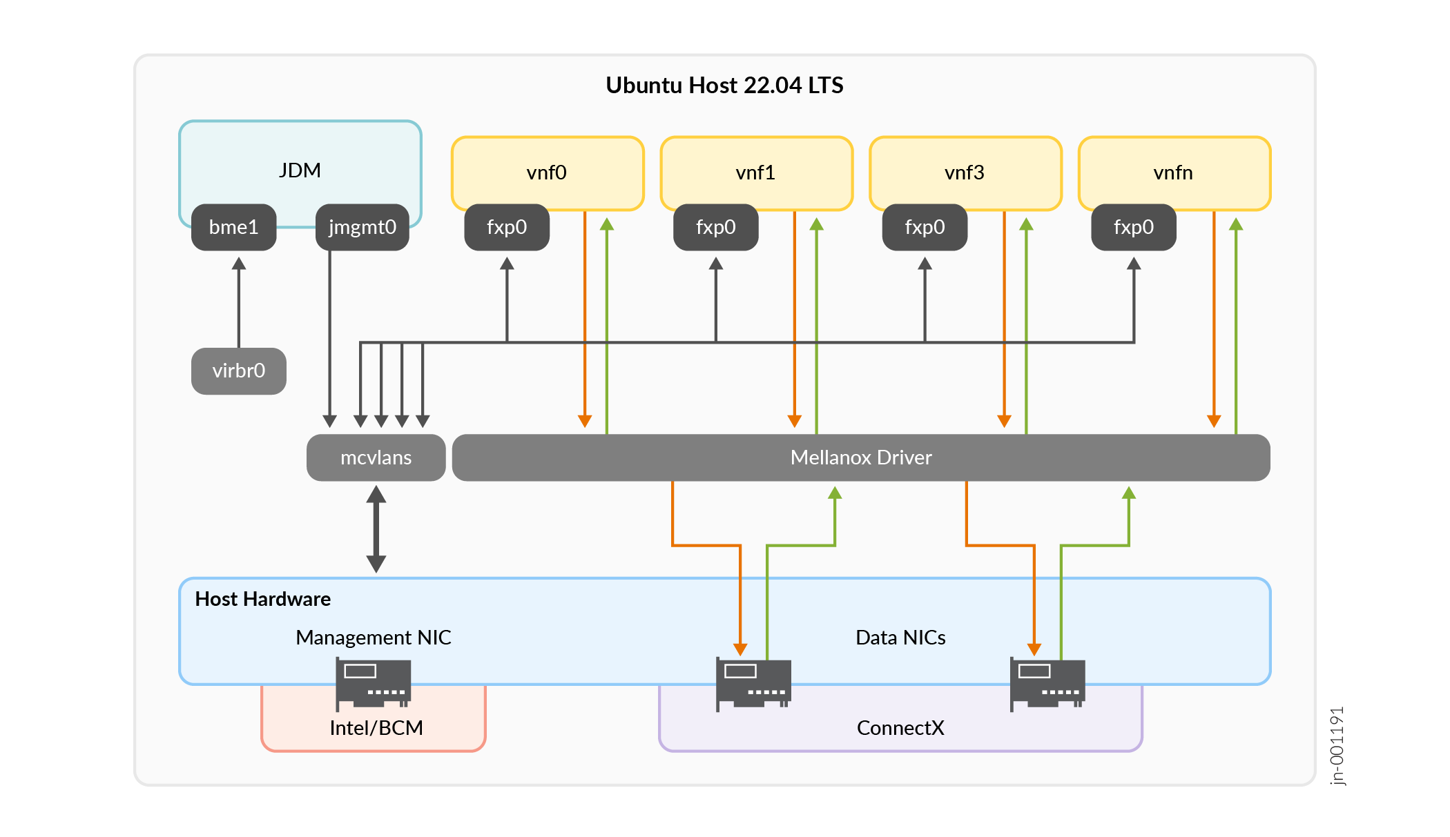
Network Interfaces
JDM installation creates the required JDM network interfaces. Table 2 shows the list of network interfaces created after JDM installation.
|
Interface Type |
Interface Name |
Interface Description |
|---|---|---|
|
JDM Management |
jmgmt0 |
|
|
vSRX Management |
fxp0 |
|
|
vSRX Datapath |
SR-IOV VFs vf-1, vf-2 |
|
Figure 1 illustrates the internal networking in the host server.
JDM Installation Workflow for vSRX Orchestration
The procedure below outlines the installation and configuration of JDM for vSRX orchestration:
Ensure all your nodes have a management IP address. Ensure you've downloaded the JDM image and the vSRX image on the JNU controller which is the MX Series router.
Add the management IP address of the Ubuntu host server in the MX Series router for JDM management. Every host server is referred with a
node-instanceID.Set up the MX Series router as the JNU controller. If you have already set up the JNU controller, skip this step.
Install the JDM from the JNU controller. During installation, the system will:
Create the Linux
known_hostsfile in the JDM for both the root and jnuadmin user accounts to store the host's public keys that the users access.Set up two-way SSH keys between the MX Series router and the JDM for the jnuadmin user.
Provision the JNU controller IP address in the JDM.
Assign an IP address for the JNU satellite in the JDM.
Launch the JDM. The JDM uses the management interface of the host server. During JDM installation, the MX Series router allocates a pool of IP addresses to the JDM. The JDM designates the first IP address from the pool to itself. The installation process also provisions the JDM with controller and satellite IP addresses that are required for the jnud process.
- Spawn vSRX Virtual Firewall instances from the JNU controller. During this process, the
system:
Copies the vSRX installer image from the MX Series router to the JDM.
Uses the baseline configuration to initiate the vSRX instance in JDM.
Copies the SSH keypair from JDM to the home directories of the firewall's root and jnuadmin user accounts.
Sends the second IP in the
ip-prefix-rangefor spawning the firewall from the JDM. The system assigns the IP addresses sequentially based on the number of instances it spawns.- Applies the baseline configuration, that includes the controller's IP address and public SSH key, and the jnud process-specific settings. The controller adds its jnuadmin user’s public SSH key to the firewall. The SSH key allows the JNU controller to securely manage the firewall once it has an IP address. The controller also establishes a one-way trust relationship with the firewall.
Waits for approximately 10 minutes for the instances to spawn. The JDM spawns the instances based on the server hardware you choose for the Ubuntu host. Based on server configuration, the JDM assigns a pair of 100 GB or 200 GB interfaces for the firewall's SR-IOV VFs.
With one-way SSH key access to the firewall granted to the jnuadmin user on MX Series router, the JNU controller retrieves the public key from the firewall. The JNU controller adds the keys to the local
authorized_keysfile of the MX Series router. The MX Series router uses the IP address of the firewall and starts the jnud process to make the firewall a satellite node.Wait for approximately 10 minutes for the satellites to synchronize with the controller.
The names of all
the
satellites are listed
at the
[edit chassis jnu-management] hierarchy level. The satellite schema for a
particular satellite is available
at the
[edit chassis satellites satellite-name] hierarchy
level.
For step-by-step configuration, see Install and Configure Junos Device Manager for CSDS
JDM and vSRX Virtual Firewall Upgrade Process
To upgrade the JDM and the vSRX:
Upgrade both the controllers, including both the Routing Engines. Follow the Junos OS upgrade process. See Junos® OS Software Installation and Upgrade Guide.
Upgrade the JDM from the controller using the following command.
user@mx1> request csds jdm add csds-instance-id csds-instance-id image jdm-image-path
Upgrade each vSRX instances using the following commands to copy the image and SSH login to run the Junos OS installation command.
user@mx1:~# file copy source-image-path root@satellite-ip-address:image-path-at-destination
or
user@mx1:~# scp -O source-image-path root@satellite-ip-address:image-path-at-destination
and
user@vsrx1> request system software add package-name
Follow the same sequential steps to downgrade the JDM and the vSRX. Ensure that you use the correct Junos OS image for the downgrade process.
JDM and vSRX Virtual Firewall Deletion Process
Delete vSRX Virtual Firewall Without Deleting JDM
Delete vSRX from the controller using the following command. Note that this command doesn't delete the JDM.
user@mx1> request csds delete-vsrx csds-instance-id csds-instance-id
Delete JDM
Use the following command to delete an existing JDM.
user@mx1> request csds jdm delete csds-instance-id csds-instance-id
CAUTION:Proceed with caution when you use the command
request csds jdm delete csds-instance-id
                  csds-instance-id
to delete a JDM instance. The command also removes any vSRX instances that the JDM creates. In this scenario, you have to reinstall the JDM and the vSRX Virtual Firewalls. Ensure that you do not manually delete the JDM from the host. Doing so may cause the JDM or vSRX deployments to fail due to known-host entries on the controller.To retain the vSRX, perform only JDM add operation to either upgrade or downgrade JDM. See JDM and vSRX Virtual Firewall Upgrade Process.