Rack Types Introduction
Rack types define the type and number of leaf devices, access switches and/or generic systems that are used in rack builds. Since rack types don't define specific vendors or their devices, you can design your network before choosing hardware. If you need to create a template, you'll use rack types to build the structure of your network. Rack types include the details in the following sections:
Predefined Rack Types
| Rack Type Name | Number and Type of Leafs | Leaf Details | Number of Generic Systems | Generic System Details |
|---|---|---|---|---|
| L2 Compute | 1 single leaf | One panel with forty-eight 10 Gbps ports
One panel with six 40 Gbps ports
|
40 | One 10 Gbps link single-homed at leaf
LAG Mode: No LAG
Roles:
Leaf / Access
|
| L2 ESI 2x Links | 1 ESI group | ESI group | 1 | |
| L2 HPC | 1 single leaf | single leaf | 16 | |
| L2 MLAG 2x Links | 1 MLAG pair | MLAG pair | 1 | |
| L2 MLAG Pair | 1 MLAG pair | MLAG pair | 48 | |
| L2 One Leaf | 1 single leaf | single leaf | 48 | |
| L2 Virtual | 1 single leaf | Seven 10 Gbps ports:
|
2 | One 10 Gbps leaf/access port /// 10 Gbps link single-homed at leaf |
| L2 Virtual 2xDual | 2 single leafs | single leafs | 1 | |
| L2 Virtual 2xMLAG | 2 MLAG pairs | MLAG pairs | 1 | |
| L2 Virtual Dual | 2 single leafs | single leafs | 2 | |
| L2 Virtual MLAG | 1 MLAG pair | MLAG pair | 2 | |
| MLAG Compute | 1 MLAG pair | MLAG pair | 40 |
| Rack Type Name | Number and Type of Leafs | Leaf Details | Number of Access Switches | Access Switch Details | Number of Generic Systems | Generic System Details |
|---|---|---|---|---|---|---|
| L2 Access 4x | 1 single leaf | 4 single switches | 4 | |||
| L2 ESI Acs Dual | 1 ESI group | 1 ESI group | 3 | |||
| L2 ESI Acs Single | 1 ESI group | 1 ESI group | 2 | |||
| L2 MLAG 1x access | 1 MLAG pair | 1 single switch | 2 | |||
| L2 MLAG 2acs+1lef | 1 MLAG pair, 1 single leaf | 3 single switches | 4 | |||
| L2 MLAG 2x access | 1 MLAG pair | 2 single switches | 2 | |||
| L2 One Access | 1 single leaf | 1 single switch | 4 |
| Rack Type Name | Number and Type of Leafs | Leaf Details | Number of Access Switches | Access Switch Details | Number of Generic Systems | Generic System Details |
|---|---|---|---|---|---|---|
| Collapsed 1xleaf | 1 single leaf | Two 10 Gbps mesh links Roles:
|
1 single switch | One 10 Gbps leaf link single-homed at leaf
LAG Mode: LACP
(Active)
Roles:
|
2 | One 10 Gbps link single-homed at access
LAG Mode: No
LAG
Roles:
|
| Collapsed 2xleafs | 1 ESI group | Two 10 Gbps mesh links Roles:
|
None | N/A | 2 | One 10 Gbps link dual-homed at ESI leaf
LAG Mode: LACP
(Active)
Roles:
|
Summary
| Summary | Description |
|---|---|
| Name (and optional description) | A unique name to identify the rack type, 17 characters or fewer |
| Fabric connectivity design |
|
Leaf Devices
| Leaf Devices | Description |
|---|---|
| Name | 64 characters or fewer |
| Leaf Logical Device | Used as ToR leaf switch network device(s) |
| Links per spine, and Link speed (L3 Clos Only) | Number of leaf-spine links and their speed. |
| Redundancy Protocol |
CAUTION: Make sure that the intended platform supports the chosen redundancy protocol. For example, L3 MLAG peers are not supported on SONiC, and ESI is supported on Junos only.
|
| Tags | User-specified. Select tags from drop-down list generated from global catalog or create tags on-the-fly (which then become part of the global catalog). Tags used in rack types are embedded, so any subsequent changes to tags in the global catalog do not affect the rack type. |
Access Switches
ESI support at the access layer is supported. You can dual-home generic systems (servers) to access switches. We're leveraging EVPN at the access layer to enable ESI-LAG towards the generic system while keeping the L2 only nature of the access switch role.
Supported/Unsupported Topologies for ESI Access:
- Each member of an access switch pair dual-attached to the leaf pair is supported.
- Each member of an access switch pair single-attached to the leaf pair is supported.
- One member of an access switch pair dual-attached to the leaf pair and the other member of an access switch pair single-attached to the leaf pair is not supported.
This is supported on 3-Stage, 5-Stage, and collapsed fabric blueprints. Day 2 topology changes are available through Add/Edit/Remove Racks.
Requirements for the switch model acting as Access Switch are:
- EVPN-VxLAN with VTEP support is required on the Access Switches.
- L2 VxLAN only is required, L3 VxLAN (RIOT) is not required, and will continue to be available only at the leaf layer.
When creating and managing access switches, follow the general workflow for building a network while taking into account the following options and design considerations.
-
When creating logical devices, on leaf switches facing an access switch, select the port role access, and configure ports in the access switch logical device.
-
Create an interface map per standard procedure.
-
Create a rack type with configured access switches.
-
Create a template that uses rack types with access switches.
-
Create a blueprint and build it following the general workflow. You can perform the same tasks as for other blueprints.
| Access Switches | Description |
|---|---|
| Name | 64 characters or fewer |
| Access Switch count | Number of access switches. These switches share the same logical link group. |
| Logical Device | Logical device is applied to this access switch. |
| Redundancy Protocol |
|
| Tags | User-specified. Select tags from drop-down list generated from global catalog or create tags on-the-fly (which then become part of the global catalog). Tags used in rack types are embedded, so any subsequent changes to tags in the global catalog do not affect the rack type. |
| Logical Link |
|
Generic Systems
| Generic Systems | Description |
|---|---|
| Name | 64 characters or fewer |
| Generic system count | Number of systems in the set |
| Port Channel ID Min, and Max | Port channel IDs are used when rendering leaf device port-channel configuration towards generic systems. default: 1-4096. You can customize this field. (Prior to Apstra version 4.2.0, all non-default port channel numbers had to be unique per blueprint. Port channel ranges could not overlap. This requirement has been relaxed, and now they need only be unique per system.) |
| Logical Device | The generic system network device |
| Tags | User-specified. Select tags from drop-down list generated from global catalog or create tags on-the-fly (which then become part of the global catalog). Useful for specifying generic systems as servers or external routers on nodes and links. Tags used in rack types are embedded, so any subsequent changes to tags in the global catalog do not affect the rack type. |
| Logical Link |
|
You can also add generic systems to blueprints as a Day 2 operation. For more information, see Add Generic System.
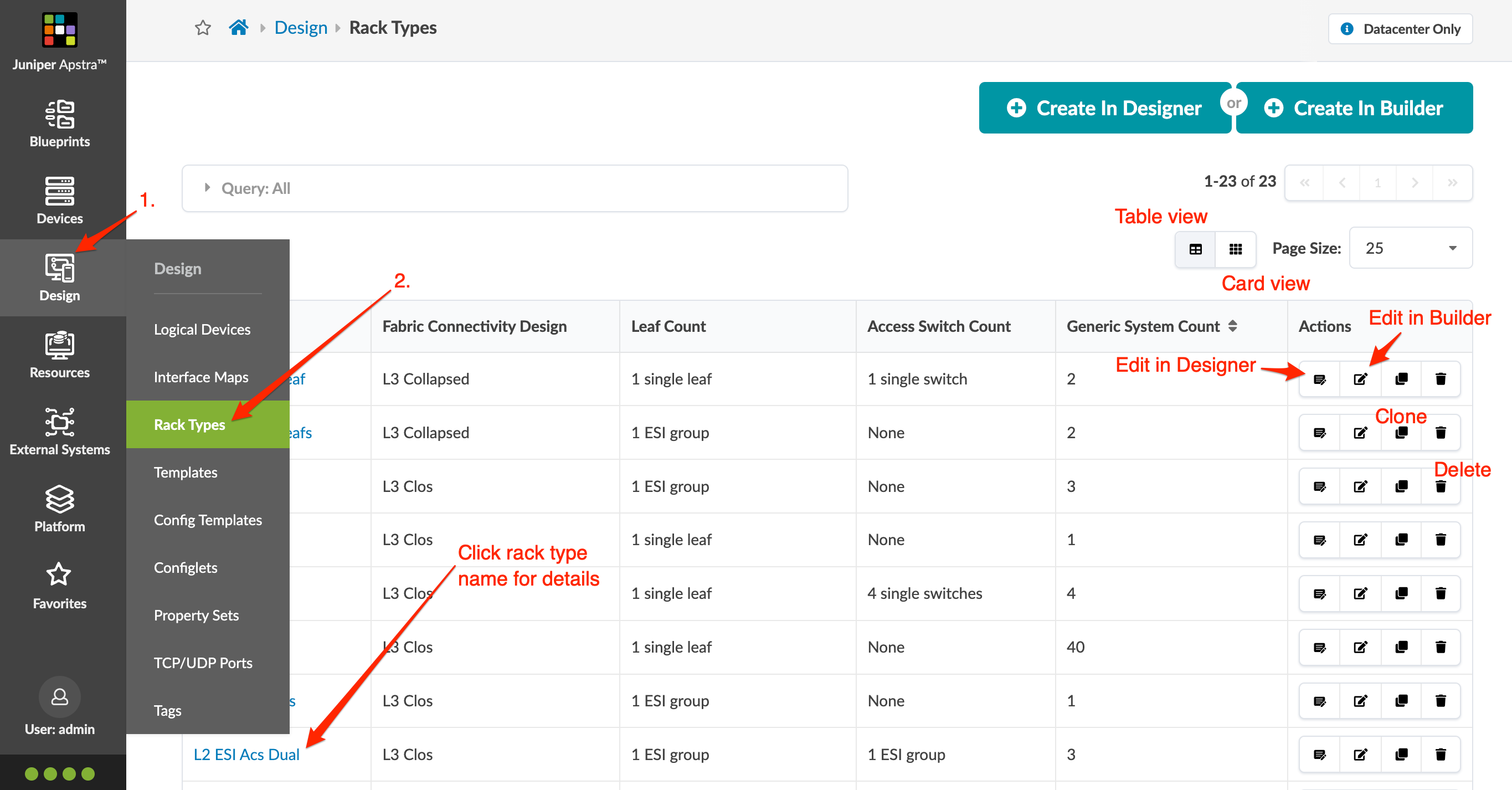
Rack Types in Apstra GUI
From the left navigation menu, navigate to Design > Rack Types to go to rack types in the design (global) catalog. Click a rack type name to see its details. You can create, clone, edit, and delete rack types. You can create rack types using the builder, or starting in Apstra version 4.2.0, you can use the designer, a graphical interface for creating rack types.