Maintaining the SRX5800 Power System
Maintaining SRX5800 Firewall Power Supplies
Purpose
For optimum firewall performance, verify the condition of the power supplies.
Action
On a regular basis:
To check the status of the power supplies, issue the
show chassis environment pemcommand. The output is similar to the following:user@host> show chassis environment pem PEM 0 status: State Online Temperature OK AC Input: OK DC Output Voltage Current Power Load 50 6 300 17 PEM 1 status: State Online Temperature OK AC Input: OK DC Output Voltage Current Power Load 50 3 150 8Make sure that the power and grounding cables are arranged so that they do not obstruct access to other firewall components.
Routinely check the status LEDs on the power supply faceplates and the craft interface to determine if the power supplies are functioning normally.
Check the red and yellow alarm LEDs on the craft interface. Power supply failure or removal triggers an alarm that causes one or both of the LEDs to light. You can display the associated error messages by issuing the following command:
user@host> show chassis alarms
Periodically inspect the site to ensure that the grounding and power cables connected to the device are securely in place and that there is no moisture accumulating near the device.
Replacing an SRX5800 Firewall AC Power Supply or High-Voltage Second-Generation Universal (HVAC/HVDC) Power Supply
To replace an AC or High-Voltage Second-Generation Universal (HVAC/HVDC) power supply, perform the following procedures:
- Removing an SRX5800 Firewall AC Power Supply or High-Voltage Second-Generation Universal (HVAC/HVDC) Power Supply
- Installing an SRX5800 Firewall AC Power Supply or High-Voltage Second-Generation Universal (HVAC or HVDC) Power Supply
Removing an SRX5800 Firewall AC Power Supply or High-Voltage Second-Generation Universal (HVAC/HVDC) Power Supply
Before you remove a power supply, be aware of the following:
The minimum number of power supplies must be present in the firewall at all times.
To maintain proper cooling and prevent thermal shutdown of the operating power supply unit, each power supply slot must contain either a power supply or a blank panel. If you remove a power supply, you must install a replacement power supply or a blank panel shortly after the removal.
After powering off a power supply, wait at least 60 seconds before turning it back on.
Before you begin to remove the AC power supply:
Ensure you understand how to prevent electrostatic discharge (ESD) damage. See Prevention of Electrostatic Discharge Damage.
Ensure that you have the following available:
ESD grounding strap
To remove an AC power supply (see Figure 1):
- Pull the power supply straight out of the chassis. The
power supply can weigh up to 12 lb (5.5 kg). Be prepared
to accept its full weight.Figure 1: Removing an AC Power Supply (Standard-Capacity Shown, High-Capacity Similar)
 Warning:
Do not touch the power connector on the top of the power supply (see Figure 2). It can contain dangerous voltages.
Figure 2: Top of the Power Supply Showing Midplane Connector Figure 3: Removing a High-Capacity Second-Generation AC Power Supply
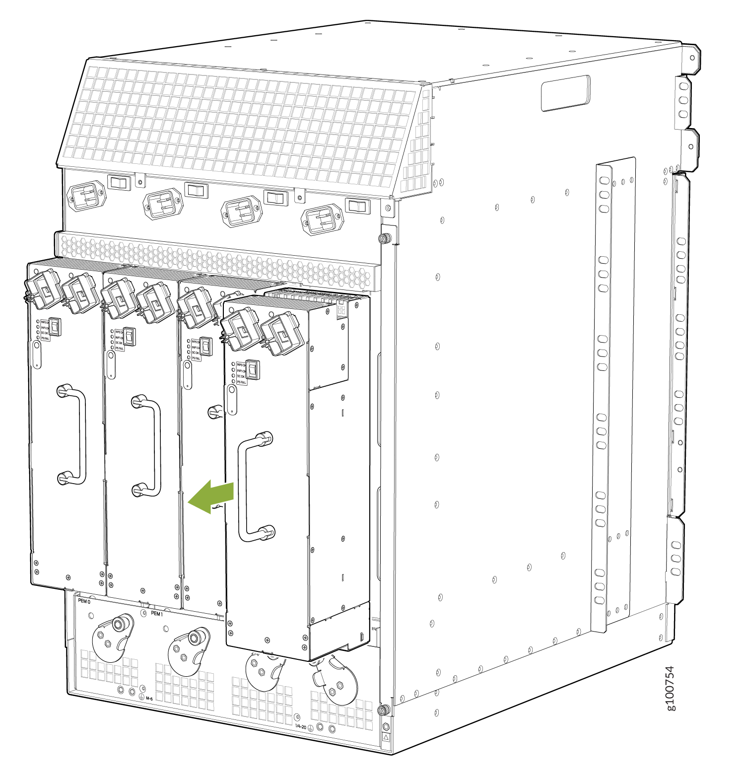 Figure 4: Removing a High-Voltage Second-Generation Universal (HVAC/HVDC) Power Supply
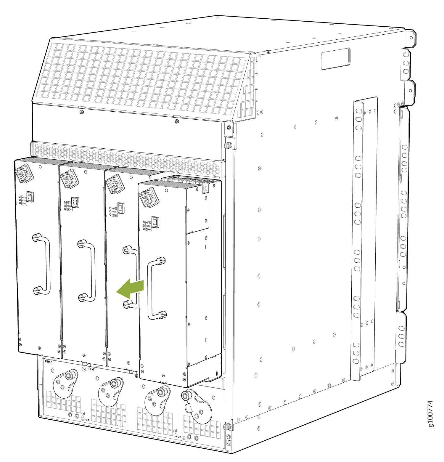
Installing an SRX5800 Firewall AC Power Supply or High-Voltage Second-Generation Universal (HVAC or HVDC) Power Supply
Before you begin to install an AC high-voltage second-generation universal (HVAC/HVDC) power supply:
Ensure you understand how to prevent electrostatic discharge (ESD) damage. See Prevention of Electrostatic Discharge Damage.
Ensure that you have the following available:
ESD grounding strap
To install an AC the high-voltage second-generation universal (HVAC/HVDC) power supply:
-
For each high-capacity or high-capacity second-generation AC power supply, move
the input mode switch to position 0 for one feed or
position 1 for two feeds (see Figure 5). We recommend that you use two AC power feeds and set the mode input switch
to 1.
Figure 5: High-Capacity AC Power Supply Input Mode Switch
 Figure 6: High-Capacity Second-Generation AC Power Supply Input Mode Switch
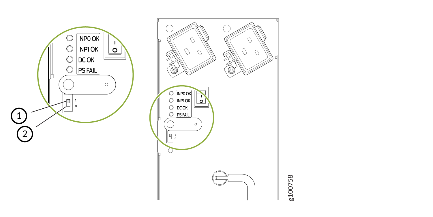 Note:
Note:Do not use a pencil to set the mode switch, because fragments can break off and cause damage to the power supply.
- Using both hands, slide the power supply straight into
the chassis until the power supply is fully seated in the chassis
slot. The power supply faceplate should be flush with any adjacent
power supply faceplates.
The small tab on the metal housing that is controlled by the release lever must be inside of the corresponding slot at the bottom of the power supply (see Figure 7). This tab is used to pull the power supply down in the chassis slot, prior to removing the power supply.
Figure 7: Installing an AC Power Supply (Standard-Capacity Shown, High-Capacity Similar)
-
While firmly pushing the handle on the power supply faceplate with one hand,
use your other hand to pull the spring-loaded locking pin in the release lever
away from the chassis and turn the release lever clockwise until it stops.
Figure 8: Installing a High-Capacity Second-Generation AC Power Supply
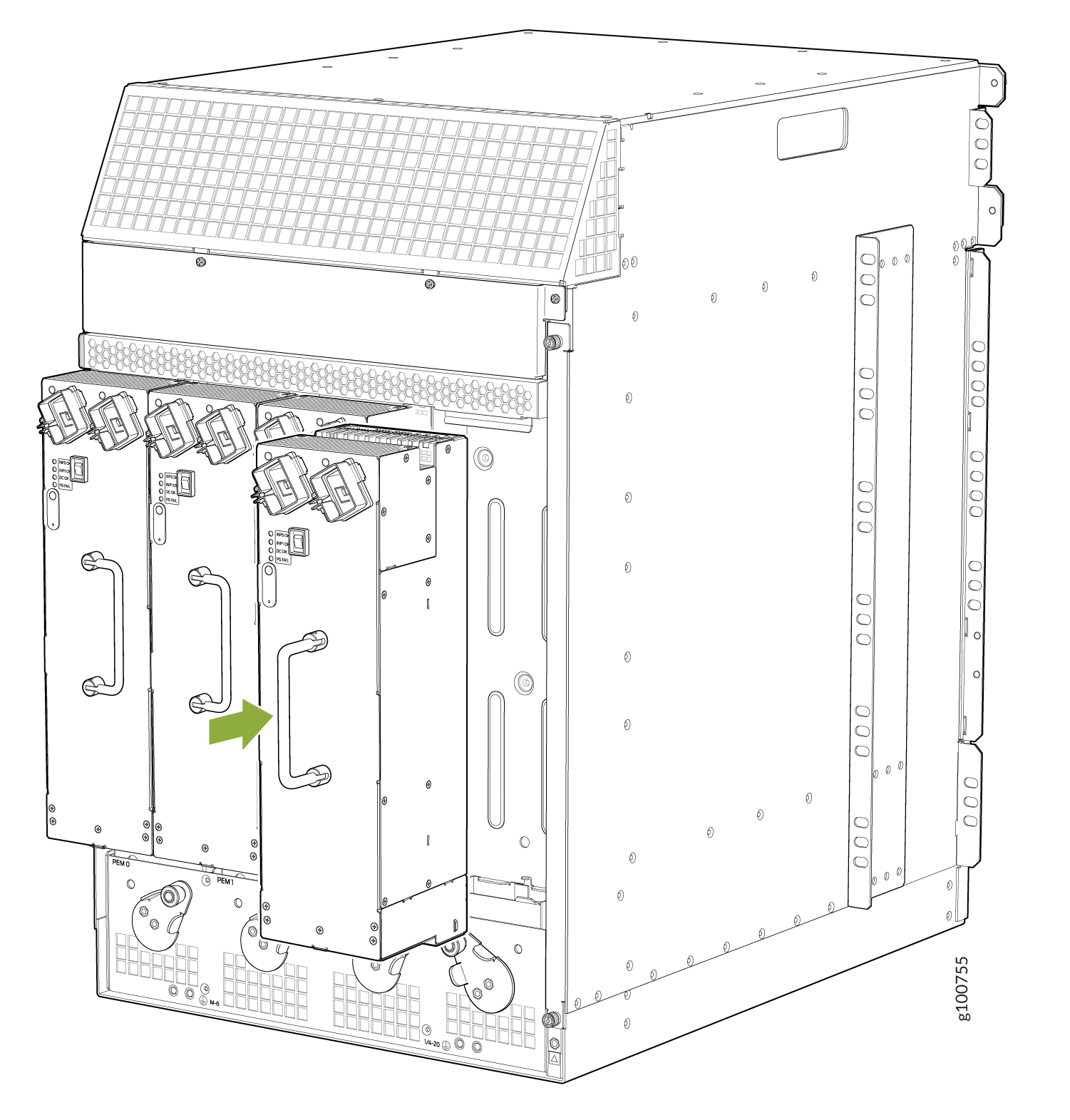 Figure 9: Installing a High-Voltage Second-Generation Universal (HVAC or HVDC) Power Supply
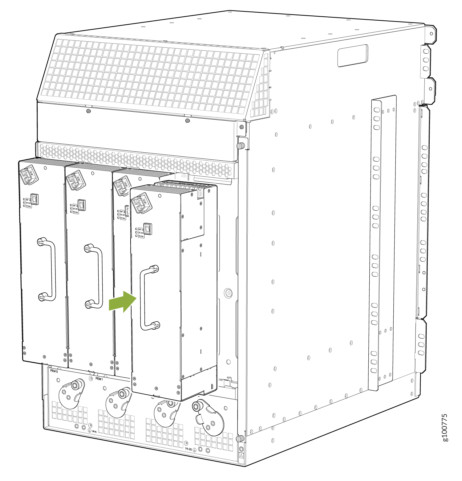
Replacing an SRX5800 Firewall AC Power Supply Cord
To replace an SRX5800 Firewall AC power supply cord, perform the following procedures:
- Disconnecting an SRX5800 Firewall AC Power Supply Cord
- Connecting an SRX5800 Firewall AC Power Supply Cord
Disconnecting an SRX5800 Firewall AC Power Supply Cord
Before you begin to disconnect an AC power supply cord:
-
Ensure you understand how to prevent electrostatic discharge (ESD) damage. See Prevention of Electrostatic Discharge Damage.
Ensure that you have the following available:
-
ESD grounding strap
To disconnect an AC power cord:
Connecting an SRX5800 Firewall AC Power Supply Cord
Before you begin to connect an AC power supply cord:
Ensure you understand how to prevent electrostatic discharge (ESD) damage. See Prevention of Electrostatic Discharge Damage.
Ensure that you have the following available:
ESD grounding strap
Power cords are not supplied with the firewall. You must order the power cords separately.
To connect an AC power cord:
Replacing an SRX5800 Firewall DC Power Supply
To replace a DC power supply, perform the following procedures:
Removing an SRX5800 Firewall DC Power Supply
Before you remove a power supply, be aware of the following:
The minimum number of power supplies must be present in the firewall at all times.
Before you perform DC power procedures, ensure there is no power to the DC circuit. To ensure that all power is off, locate the circuit breaker on the panel board that services the DC circuit, switch the circuit breaker to the off position, and tape the switch handle of the circuit breaker in the off position.
To maintain proper cooling and prevent thermal shutdown of the operating power supply unit, each power supply slot must contain either a power supply or a blank panel. If you remove a power supply, you must install a replacement power supply or a blank panel shortly after the removal.
After powering off a power supply, wait at least 60 seconds before turning it back on.
Before you begin to remove a DC power supply:
Ensure you understand how to prevent electrostatic discharge (ESD) damage. See Prevention of Electrostatic Discharge Damage.
Ensure that you have the following available:
ESD grounding strap
7/16–in. nut driver or socket wrench
To remove a DC power supply (see Figure 10):
- Pull the power supply straight out of the chassis. The
power supply can weigh up to 12 lb (5.5 kg). Be prepared
to accept its full weight.Figure 10: Removing a DC Power Supply from the Firewall (Standard-Capacity Shown, High-Capacity Similar)
 Warning:
Do not touch the power connector on the top of the power supply (see Figure 11). It can contain dangerous voltages.
Figure 11: Top of the Power Supply Showing Midplane Connector
Installing an SRX5800 Firewall DC Power Supply
Before you begin to install a DC power supply:
Ensure you understand how to prevent electrostatic discharge (ESD) damage. See Prevention of Electrostatic Discharge Damage.
Ensure that you have the following available:
ESD grounding strap
7/16–in. nut driver or socket wrench
Before you perform DC power procedures, ensure there is no power to the DC circuit. To ensure that all power is off, locate the circuit breaker on the panel board that services the DC circuit, switch the circuit breaker to the off position, and tape the switch handle of the circuit breaker in the off position.
To install a DC power supply (see Figure 12):
- Using both hands, slide the power supply straight into
the chassis until the power supply is fully seated in the chassis
slot.
The small tab on the metal housing that is controlled by the release lever must be inside of the corresponding slot at the bottom of the power supply (see Figure 12). This tab is used to pull the power supply down in the chassis slot, prior to removing the power supply.
Figure 12: Installing a DC Power Supply (Standard Capacity Shown, High-Capacity Similar)
- Secure each power cable lug to the terminal studs, first
with the split washer, then with the nut. CAUTION:
You must ensure that power connections maintain the proper polarity. The power source cables might be labeled (+) and (–) to indicate their polarity. There is no standard color coding for DC power cables. The color coding used by the external DC power source at your site determines the color coding for the leads on the power cables that attach to the terminal studs on each power supply.
For a standard-capacity power supply:
- Apply between 23 lb-in. (2.6 Nm) and 25 lb-in.
(2.8 Nm) of torque to each nut (see Figure 13).Figure 13: Connecting DC Power to a Standard-Capacity DC Power Supply
For a high-capacity power supply:
- Apply between 23 lb-in. (2.6 Nm) and 25 lb-in.
(2.8 Nm) of torque to each nut (see Figure 14).Figure 14: Connecting DC Power to a High-Capacity DC Power Supply
CAUTION:Ensure that each power cable lug seats flush against the surface of the terminal block as you are tightening the nuts. Ensure that each nut is properly threaded onto the terminal stud. The nut should be able to spin freely with your fingers when it is first placed onto the terminal stud. Applying installation torque to the nut when improperly threaded may result in damage to the terminal stud.
CAUTION:The maximum torque rating of the terminal studs on the DC power supply is 36 in-lb. (4.0 Nm). The terminal studs may be damaged if excessive torque is applied. Use only a torque-controlled driver or socket wrench to tighten nuts on the DC power supply terminal studs.
Note:The DC power supplies in slots PEM0 and PEM1 must be powered by dedicated power feeds derived from feed A, and the DC power supplies in PEM2 and PEM3 must be powered by dedicated power feeds derived from feed B. This configuration provides the commonly deployed A/B feed redundancy for the system.
- Apply between 23 lb-in. (2.6 Nm) and 25 lb-in.
(2.8 Nm) of torque to each nut (see Figure 13).
Replacing an SRX5800 Firewall DC Power Supply Cable
To replace an SRX5800 Firewall DC power supply cable, perform the following procedures:
- Disconnecting an SRX5800 Firewall DC Power Supply Cable
- Connecting an SRX5800 Firewall DC Power Supply Cable
Disconnecting an SRX5800 Firewall DC Power Supply Cable
Before you begin to disconnect a DC power supply cable:
Ensure you understand how to prevent electrostatic discharge (ESD) damage. See Prevention of Electrostatic Discharge Damage.
Ensure that you have the following available:
ESD grounding strap
7/16–in. nut driver or socket wrench
Before you perform DC power procedures, ensure there is no power to the DC circuit. To ensure that all power is off, locate the circuit breaker on the panel board that services the DC circuit, switch the circuit breaker to the off position, and tape the switch handle of the circuit breaker in the off position.
To disconnect a power cable for a DC power supply:
- Switch off the dedicated customer site circuit breaker for the power supply being removed. Follow your site's procedures for ESD.
- Make sure that the voltage across the DC power source cable leads is 0 V and that there is no chance that the cables might become active during the removal process.
- Verify that the input LEDs on the power supply are not lit (INPUT OK for a standard-capacity power supply, INP0 OK and INP1 OK for a high-capacity power supply).
- Remove the power cable from the external DC power source.
- Attach an ESD grounding strap to your bare wrist, and connect the strap to one of the ESD points on the chassis.
- Move the DC circuit breaker on the power supply faceplate to the off (O) position.
- Remove the clear plastic cover protecting the terminal studs on the faceplate.
- Remove the nut and washer from the terminal studs. (Use a 7/16–in. nut driver or socket wrench.)
- Remove the cable lug from the terminal studs.
- For a standard-capacity power supply, loosen the captive screw on the cable restraint on the lower edge of the power supply faceplate.
- Carefully move the power cable out of the way.
Connecting an SRX5800 Firewall DC Power Supply Cable
Before you begin to connect a DC power supply cable:
Ensure you understand how to prevent electrostatic discharge (ESD) damage. See Prevention of Electrostatic Discharge Damage.
Ensure that you have the following available:
ESD grounding strap
7/16–in. nut driver or socket wrench
Before you perform DC power procedures, ensure there is no power to the DC circuit. To ensure that all power is off, locate the circuit breaker on the panel board that services the DC circuit, switch the circuit breaker to the off position, and tape the switch handle of the circuit breaker in the off position.
To connect a power cable for a DC power supply:
- Secure the power cable lug to the terminal studs, first
with the split washer, then with the nut. Apply between 23 lb-in.
(2.6 Nm) and 25 lb-in. (2.8 Nm) of torque to each nut
(see Figure 15 and Figure 16).Figure 15: Connecting Power Cables to a Standard Capacity DC Power SupplyFigure 16: Connecting DC Power Cables to a High-Capacity DC Power Supply
Upgrading an SRX5800 Firewall from Standard-Capacity to High-Capacity Power Supplies
You can replace the standard-capacity power supplies in the SRX5800 Firewall with either two or four high-capacity power supplies of the same input type (AC or DC). Two high-capacity power supplies provide adequate power for a fully loaded chassis; installing four high-capacity power supplies provides redundancy in case one power supply in either zone fails. You do not need to power off the device to upgrade to high-capacity power supplies.
The firewall cannot be powered from standard-capacity and high-capacity power supplies simultaneously. The one exception is during the process of replacing standard-capacity power supplies with high-capacity power supplies, when it is permissible to have both types installed briefly.
The firewall cannot be powered from AC and DC power supplies simultaneously. The first type of power supply detected by the firewall when initially powered on determines the type of power supply allowed by the firewall. All installed power supplies of the other type are disabled by the firewall. If you install a power supply of the other type while the firewall is operating, the firewall disables the power supply and generates an alarm.
The following procedures describe how to upgrade from standard-capacity power supplies to high-capacity power supplies of the same input type (AC or DC) without interrupting power to the firewall components. Choose the procedure that matches your firewall configuration:
To upgrade a firewall that has three or four standard-capacity AC power supplies to two or four high-capacity AC power supplies:
Limit to five minutes or less the time during which standard-capacity AC power supplies and high-capacity AC power supplies are installed in the firewall at the same time.
To upgrade a firewall that has two standard-capacity DC power supplies to two or four high-capacity DC power supplies:
-
Ensure that the Firewall is running Junos OS Release 12.1X44-D10 or later. Earlier Junos OS releases do not support high-capacity DC power supplies.
-
If you have not already done so, replace both standard-capacity fan trays with high-capacity fan trays. Also replace the standard-capacity air filter with a high-capacity air filter. For more information, see Replacing an SRX5800 Firewall Fan Tray and Replacing the SRX5800 Firewall Air Filter.
-
Install high-capacity DC power supplies in the two empty PEM slots in the back of the chassis. See Installing an SRX5800 Firewall DC Power Supply for instructions on installing DC power supplies.
Check the LEDs on the faceplate of each of the new power supplies to confirm that they are operating properly.
-
Remove both of the standard-capacity power supplies from the firewall. See Removing an SRX5800 Firewall DC Power Supply for instructions on removing DC power supplies.
If you are installing four high-capacity DC power supply to achieve 2+2 redundancy, install high-capacity DC power supplies in the slots vacated in Step 5.
Check the LEDs on the faceplate of each of the new power supplies to confirm that they are operating properly.
To upgrade a firewall that has four standard-capacity DC power supplies to two or four high-capacity DC power supplies:
-
Ensure that the firewall is running Junos OS Release 12.1X44-D10 or later. Earlier Junos OS releases do not support high-capacity DC power supplies.
-
If you have not already done so, replace both standard-capacity fan trays with high-capacity fan trays. Also replace the standard-capacity air filter with a high-capacity air filter. For more information, see Replacing an SRX5800 Firewall Fan Tray and Replacing the SRX5800 Firewall Air Filter.
Check the LEDs on all four power supply faceplates to ensure that they are operating properly.
-
Remove the standard-capacity power supply from slot PEM0. See Removing an SRX5800 Firewall DC Power Supply for instructions on removing DC power supplies.
-
Install a high-capacity DC power supply in the PEM0 slot in the back of the chassis. See Installing an SRX5800 Firewall DC Power Supply for instructions on installing DC power supplies.
Repeat Step 4 and Step 5 to replace the standard-capacity DC power supply in the PEM1 slot with a high-capacity DC power supply.
Check the LEDs on the faceplate of each of the new power supplies to confirm that they are operating properly.
-
Remove the two standard-capacity power supplies from the PEM2 and PEM3 slots. See Removing an SRX5800 Firewall DC Power Supply for instructions on removing DC power supplies.
-
If you are upgrading to four high-capacity DC power supplies to achieve 2+2 redundancy, install high-capacity DC power supplies in the PEM2 and PEM3 slots. See Installing an SRX5800 Firewall DC Power Supply for instructions on installing DC power supplies.
Check the LEDs on the faceplate of each of the new power supplies to confirm that they are operating properly.