ON THIS PAGE
SRX5800 Firewall Standard-Capacity AC Power Supply—SRX5800-PWR-AC
SRX5800 Firewall High-Capacity AC Power Supply—SRX5800-PWR-4100-AC
SRX5800 Firewall High-Capacity Second-Generation AC Power Supply—SRX5800-HPWR-AC
AC Power Circuit Breaker Requirements for the SRX5800 Firewall
High-Voltage Second-Generation Universal (HVAC/HVDC) Power Supply for SRX5800 Firewall—MX960-PSM-HV
SRX5800 Firewall Standard-Capacity DC Power Supply—SRX5800-PWR-DC
SRX5800 Firewall High-Capacity DC Power Supply—SRX5800-HPWR-DC
DC Power Circuit Breaker Requirements for the SRX5800 Firewall
SRX5800 Power System
SRX5800 Firewall Power System Overview
The SRX5800 Firewall uses either AC or DC power supplies. The firewall is configurable with two to four AC power supplies or two or four DC power supplies. The power supplies connect to the midplane, which distributes the different output voltages produced by the power supplies to the firewall components, depending on their voltage requirements.
Table 1 describes the different types of power supplies available.
|
Power Supply Type |
Juniper Model Number |
Input Condition (If Any) |
Maximum Output |
Redundancy |
Power Distribution |
|---|---|---|---|---|---|
|
AC standard-capacity |
SRX5800-PWR-AC |
1700 W |
3+1 |
Shared |
|
|
AC high-capacity |
SRX5800-PWR-4100-AC |
One AC input |
1700 W |
2+2 |
Zoned |
|
Two AC inputs |
4100 W |
||||
|
High-Capacity Second-Generation AC Power Supply |
SRX5800-HPWR-AC |
One AC input |
2550 W |
||
|
Two AC inputs |
5100 W |
||||
|
High-Voltage Second-Generation Universal (HVAC/HVDC) Power Supply |
MX960-PSM-HV |
5100 W |
|||
|
DC standard-capacity |
SRX5800-PWR-DC |
1700 W |
|||
|
DC high-capacity |
SRX5800-HPWR-DC |
One DC input |
1700 W |
||
|
Two DC inputs |
4100 W |
The firewall must be running Junos OS Release 10.4 or later in order to use high-capacity AC power supplies. The firewall must be running Junos OS Release 12.1X44-D10 or later in order to use high-capacity DC power supplies.
The firewall must be running Junos OS Release 21.4R1 or later in order to use high-capacity second-generation AC and high-voltage second-generation universal (HVAC or HVDC) power supplies.
Redundant power supplies are hot-removable and hot-insertable. Each power supply is cooled by its own internal cooling system.
Devices configured from the factory with DC power supplies are shipped with a blank panel installed over the power distribution modules. Devices configured with AC power supplies have no blank panel.
The firewall cannot be powered from AC and DC power supplies simultaneously. The first type of power supply detected by the firewall when initially powered on determines the type of power supply allowed by the firewall. All installed power supplies of the other type are disabled by the firewall. If you install a power supply of the other type while the firewall is operating, the firewall disables the power supply and generates an alarm.
When the firewall is powered by standard-capacity AC power supplies, the firewall contains either three or four AC power supplies, located at the rear of the chassis in slots PEM0 through PEM3 (left to right). Each power supply provides power to all components in the firewall. When three power supplies are present, they share power almost equally within a fully populated system. Four power supplies provide full power redundancy. If one power supply fails or is removed, the remaining power supplies instantly assume the entire electrical load without interruption. Three power supplies provide the maximum configuration with full power for as long as the firewall is operational.
When the firewall is powered by either standard- or high-capacity DC power supplies, or high-capacity AC power supplies, or by high-capacity second-generation AC power supplies, or high-voltage second-generation universal (HVAC or HVDC) power supplies power distribution within the chassis is divided into zones, as described in Table 2.
Zone |
Power Supplies |
Provide Power To: |
|---|---|---|
Zone 0 |
|
|
Zone 1 |
|
|
Figure 1 shows the distribution of power from the power supplies to the chassis components in an SRX5800 Firewall chassis powered by DC power supplies, or high-capacity AC power supplies, or high-capacity second-generation AC, or high-voltage second-generation universal (HVAC or HVDC) power supplies.
The craft interface draws its power from the SCBs installed in the SCB slots 0, 1, and 2 at the center of the card cage. In the standard configuration, with SCBs in slots 0 and 1, the craft interface is powered on even when one of the two zones loses power. But if the chassis only has one SCB installed, the craft interface draws all of its power from that card, and consequently is powered off if the zone in which that SCB is installed loses power.
You can install either two or four DC power supplies, or high-capacity AC power supplies, or high-capacity second-generation AC, or high-voltage second-generation universal (HVAC or HVDC) power supplies. Two power supplies are required to power the two zones, while four power supplies provide full redundancy for both zones. The power supplies in slots PEM0 and PEM2 form a redundant pair, as do the power supplies in slots PEM1 and PEM3. When two power supplies are installed for a zone, they share the load. If a power supply fails, its redundant power supply assumes the full load of that zone without interruption.
If you do install only two power supplies, they must be installed so that one is in an odd-numbered slot and the other is in an even-numbered slot. For example, you can install one high-capacity AC power supply in each of the slots PEM0 and PEM1.
SRX5800 Firewall Standard-Capacity AC Power Supply—SRX5800-PWR-AC
Each standard-capacity AC power supply (SRX5800-PWR-AC) has a corresponding AC appliance inlet located in the chassis directly above the power supply. Each inlet requires a dedicated AC power feed and a dedicated 15 A (250 VAC) circuit breaker. See Figure 2.
To meet safety and electromagnetic interference (EMI) requirements and to ensure proper operation, the firewall chassis must be adequately grounded before power is connected. See Grounding the SRX5800 Firewall for instructions.
SRX5800 Firewall Standard-Capacity AC Power Supply LEDs
Each standard-capacity AC power supply faceplate contains three LEDs that indicate the status of the power supply (see Table 3). The power supply status is also reflected in two LEDs on the craft interface. In addition, a power supply failure triggers the red alarm LED on the craft interface.
Label |
Color |
State |
Description |
|---|---|---|---|
AC OK |
Green |
Off |
AC power applied to power supply is not within the normal operating range. |
On |
AC power applied to power supply is within the normal operating range. |
||
DC OK |
Green |
Off |
DC power outputs generated by the power supply are not within the normal operating ranges. |
On |
DC power outputs generated by the power supply are within the normal operating ranges. |
||
PS FAIL |
Red |
Off |
Power supply is functioning normally. |
On |
Power supply is not functioning normally. Check AC OK and DC OK LEDs for more information. |
SRX5800 Firewall High-Capacity AC Power Supply—SRX5800-PWR-4100-AC
High-capacity AC power supplies (SRX5800-PWR-4100-AC) provide a maximum of 4100 W of power each. Two high-capacity power supplies are required, and you can install four high-capacity power supplies for redundancy. Each high-capacity AC power supply has two corresponding AC appliance inlets: one located in the chassis directly above the power supply and one located near the top edge of the power supply itself. For each power supply, you connect one power cord to the inlet on the chassis above the power supply and one power cord to the inlet on the power supply itself. Each inlet you connect requires a dedicated AC power feed and a dedicated 15 A (250 VAC) circuit breaker. See Figure 3.
The firewall cannot be powered from standard-capacity and high-capacity AC power supplies simultaneously. The one exception is during the process of replacing standard-capacity AC power supplies with high-capacity AC power supplies, when it is permissible to have both types installed briefly.
The high-capacity power supply will operate with only one of its two AC inlets connected to an AC power feed. However, its DC output will be limited to a maximum of 1700 W. We recommend that you connect two AC power feeds to each high-capacity AC power supply.
The firewall must be running Junos OS Release 10.4 or later in order to use high-capacity AC power supplies.
Each high-capacity AC power supply has an input mode switch, covered by a small metal plate. The input mode switch tells the system the number of AC power feeds it should expect. The input mode switch settings are described in Table 4. The default setting is 1.
Mode Switch Setting |
AC Inputs |
Result |
|---|---|---|
1 |
Both AC inlets powered |
AC output of 4100 W AC OK LED lights |
Only one AC inlet powered |
AC output of 1700 W PS FAIL LED lights |
|
0 |
Both AC inlets powered |
AC output of 1700 W AC OK LED lights |
Only one AC inlet powered |
AC output of 1700 W AC OK LED lights |
We recommend that you set the input mode switch to 1 and connect two AC input feeds to each high-capacity AC power supply.
To meet safety and electromagnetic interference (EMI) requirements and to ensure proper operation, the firewall chassis must be adequately grounded before power is connected. See Grounding the SRX5800 Firewall for instructions.
SRX5800 Firewall High-Capacity AC Power Supply LEDs
Each high-capacity AC power supply faceplate contains four LEDs that indicate the status of the power supply (see Table 5). The power supply status is also reflected in two LEDs on the craft interface. In addition, a power supply failure triggers the red alarm LED on the craft interface.
Label |
Color |
State |
Description |
|---|---|---|---|
AC-1 OK |
Green |
Off |
AC power applied to power supply at the upper appliance inlet is not within the normal operating range. |
On |
AC power applied to power supply at the upper appliance inlet is within the normal operating range. |
||
AC-2 OK |
Green |
Off |
AC power applied to power supply at the lower appliance inlet is not within the normal operating range. |
On |
AC power applied to power supply at the lower appliance inlet is within the normal operating range. |
||
DC OK |
Green |
Off |
DC power outputs generated by the power supply are not within the normal operating ranges. |
On |
DC power outputs generated by the power supply are within the normal operating ranges. |
||
PS FAIL |
Red |
Off |
Power supply is functioning normally. |
On |
Power supply is not functioning normally. Check the AC-1 OK, AC-2 OK, and DC OK LEDs for more information. |
SRX5800 Firewall High-Capacity Second-Generation AC Power Supply—SRX5800-HPWR-AC
The SRX5800 Firewall can also be powered by four High-Capacity Second-Generation AC power supplies (SRX5800-HPWR-AC). The high-capacity second-generation power supplies must be installed in adjacent slots in the chassis. They can operate in either one-feed mode or two-feed mode. The maximum inrush current per feed for a high-capacity AC power supply is 38 A per feed at 264 VAC.
In the one-feed mode, the power supplies provide power at a reduced capacity (2550 W). In the two-feed mode, the power supplies provide power at full capacity (5100 W). To operate the SRX5800 at full capacity, you must use the two-feed mode. High-capacity second-generation AC power supplies require one power cord per feed. Therefore, to operate the SRX5800 Firewall at full capacity, you need eight power cords.
Each high-capacity second-generation AC power supply accepts two AC feeds in two C19/C20 AC receptacles, both receptacles are located on the power supply. Do not use the receptacle located on the chassis. For supported power cables, see AC Power Cord Specifications for the SRX5800 Firewall.
When using the high-capacity second-generation AC power supplies in one-feed mode, plug one end of the power cord into the corresponding AC receptacle directly on the power supply and the other end into an AC outlet. When using the high-capacity second-generation AC power supply in two-feed mode, you need two power cords. Plug both power cords into the AC receptacles on the power supply the other ends of the cable into AC outlets.
In high-capacity second-generation AC power supply configurations, there are two zones that provide power to specific components in the SRX5800 Firewall. Redundancy is 1+1 per zone. Table 6 lists the components that receive power for each zone in a high-capacity AC power supply configuration.
| Chassis Power Configuration | Zone | Power Supply (PEM) | Provide Power To |
|---|---|---|---|
|
High-capacity second-generation AC power supplies |
Zone 0 |
|
|
|
High-capacity second-generation AC power supplies |
Zone 1 |
|
|
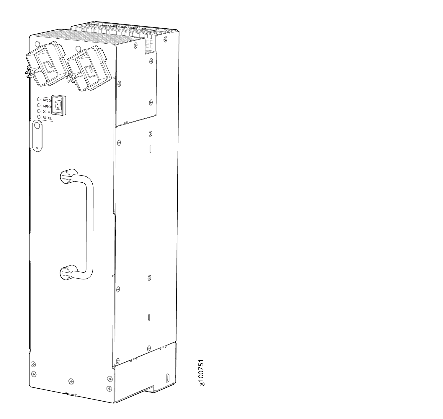
SRX5800 Firewall High-Capacity Second-Generation AC Power Supply LEDs
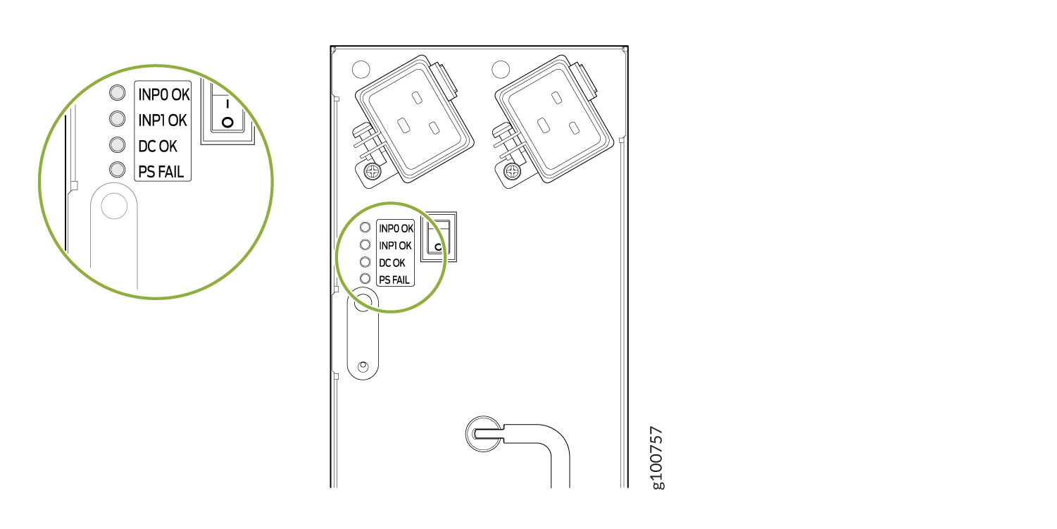
Each high-capacity second-generation AC power supply faceplate contains four LEDs that indicate the status of the power supply (see Figure 5 and Table 7).
|
Label |
Color |
State |
Description |
|---|---|---|---|
|
INP0 OK |
Green |
Off |
AC power applied to power supply is not within the normal operating range. |
|
On |
AC power applied to power supply is within the normal operating range. |
||
|
INP1 OK |
Green |
Off |
AC power applied to power supply is not within the normal operating range. |
|
On |
AC power applied to power supply is within the normal operating range. |
||
|
DC OK |
Green |
Off |
DC power outputs generated by the power supply are not within the normal operating ranges. |
|
On |
DC power outputs generated by the power supply are within the normal operating ranges. |
||
|
PS FAIL |
Red |
Off |
Power supply is functioning normally. |
|
On |
Power supply is not functioning normally. Check AC OK and DC OK LEDs for more information. |
SRX5800 Firewall AC Power Supply Specifications
Table 8 lists the AC power supply electrical specifications for both the standard-capacity, high-capacity, and high-capacity second-generation AC power supply. Table 9 lists the AC power system electrical specifications.
|
Item |
Specification |
||
|---|---|---|---|
|
Standard-Capacity |
High-Capacity |
High-Capacity Second-Generation |
|
|
Maximum output power |
1700 W |
4100 W (two AC inputs) 1700 W (one AC input) |
5100 W (two AC inputs) 2550 W (one AC input) |
|
AC input current rating |
11 A @ 240 VAC maximum |
13 A @ 240 VAC maximum per AC input (26 A per power supply when two AC inputs are used) |
16 A @ 200 VAC maximum per AC input (32 A per power supply when two AC inputs are used) |
|
AC input voltage |
Operating range: 200 to 240 VAC |
Operating range: 180 to 264 VAC |
|
|
AC input line frequency |
50 to 60 Hz |
47 to 63 Hz |
|
|
Efficiency |
~88% Note:
This value is at full load and nominal voltage. |
~91% Note:
This value is at full load and nominal voltage. |
|
|
Item |
Normal-Capacity |
High-Capacity |
High-Capacity Second-Generation |
||
|---|---|---|---|---|---|
|
Two AC inputs for each power supply |
One AC input for each power supply |
Two AC inputs for each power supply |
One AC input for each power supply |
||
|
Redundancy |
3+1 |
2+2 |
2+2 |
2+2 |
2+2 |
|
Output power (maximum) per supply |
1700 W |
4100 W |
1700 W |
5100 W |
2550 W |
|
Output power (maximum) per system |
5100 W |
8200 W |
3400 W |
1.2 KW |
5100 W |
AC Power Cord Specifications for the SRX5800 Firewall
Each AC power supply has a single AC appliance inlet located in the chassis directly above the power supply that requires a dedicated AC power feed. Most sites distribute power through a main conduit that leads to frame-mounted power distribution panels, one of which can be located at the top of the rack that houses the firewall. An AC power cord connects each power supply to the power distribution panel.
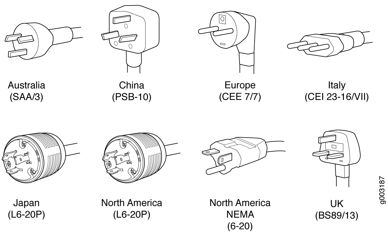
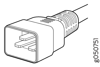
The firewall is not shipped with AC power cords. You must order power cords separately using the model number shown in Table 10. The C19 appliance coupler end of the cord inserts into the AC appliance inlet coupler, type C20 (right angle) as described by International Electrotechnical Commission (IEC) standard 60320. The plug end of the power cord fits into the power source receptacle that is standard for your geographical location.
Table 10 provides specifications and Figure 6 depicts the plug on the AC power cord provided for each country or region.
|
Country |
Model Number |
Electrical Specification |
Plug Type |
|---|---|---|---|
|
Australia |
CBL-M-PWR-RA-AU |
240 VAC, 50 Hz AC |
SAA/3 |
|
China |
CBL-M-PWR-RA-CH |
220 VAC, 50 Hz AC |
PSB-10 |
|
Europe (except Denmark, Italy, Switzerland, and United Kingdom) |
CBL-M-PWR-RA-EU |
220 or 230 VAC, 50 Hz AC |
CEE 7/7 |
|
Italy |
CBL-M-PWR-RA-IT |
230 VAC, 50 Hz AC |
CEI 23-16/VII |
|
Japan |
CBL-M-PWR-RA-JP |
220 VAC, 50 or 60 Hz AC |
NEMA L6-20P |
|
North America |
CBL-M-PWR-RA-TWLK-US |
250 VAC, 60 Hz AC |
NEMA L6-20P |
|
United Kingdom |
CBL-M-PWR-RA-UK |
240 VAC, 50 Hz AC |
BS89/13 |
Each high-capacity second-generation (MX960-PSM-5K-AC) power supply has two AC appliance inlets located in the power supply itself. Each receptacle requires a dedicated AC power feed and a dedicated breaker. Table 11 provides specifications for the high-capacity second-generation PSM.
The bend radius for the power cord cables is 7 inches. Avoid bending the cable beyond it’s bend radius when dressing the cables into the cable channels on the rack.
|
Country |
Model Number |
Electrical Specification |
Plug Type |
Graphic |
|---|---|---|---|---|
|
North America |
CBL-M-PWR-RA-JP |
250 VAC, 20 A, 50 or 60 Hz AC |
NEMA L6-20P Type NEMA Locking |
|
|
North America |
CBL-M-PWR-RA-US |
250 VAC, 20 A, 60 Hz |
NEMA 6-20, Type N6/20 |
|
|
Worldwide (Except U.S.A) |
CBL-MX-PWR-C19-C20 |
250 VAC, 16 A, 50 Hz |
EN 60320-2-2/1 |
|
|
China |
CBL-PWR-C19S-162-CH |
250 VAC, 16 A, 50Hz |
GB 1002 Type PRC/3/16 |
|
|
Continental Europe |
CBL-PWR-C19S-162-EU |
250 VAC, 16 A, 50 Hz |
CEE (7) VII Type VIIG |
|
|
Italy |
CBL-PWR-C19S-162-IT |
250 VAC, 16 A, 50 Hz |
CEI 23-16 Type I/3/16 |
|
|
Switzerland |
CBL-MX-PWR-C19-SZ |
250 VAC, 16 A, 50 Hz |
SEV 5934/2 Type 23G |
|
The AC power cord for the firewall is intended for use with the firewall only and not for any other use.
To meet safety and electromagnetic interference (EMI) requirements and to ensure proper operation, you must properly ground the firewall chassis before connecting power. See Grounding the SRX5800 Firewall for instructions.
Power cords and cables must not block access to firewall components or drape where people could trip on them.
In North America, AC power cords must not exceed 4.5 m (approximately 14.75 ft) in length, to comply with National Electrical Code (NEC) Sections 400-8 (NFPA 75, 5-2.2) and 210-52, and Canadian Electrical Code (CEC) Section 4-010(3). The cords listed in Table 10 are in compliance.
Understanding Input Mode Switch (DIP Switch) Settings
Each High-Capacity AC Power Supply and High-Capacity Second-Generation AC Power Supply has two input mode switches (DIP switches) on the faceplate. The DIP switches provide critical information to the power management subsystem to help generate alarms in case of a feed failure or a wrong connection. Each PSM has an LED per feed indicating whether the feed is active and whether the feed is properly connected. You must set the DIP switch on each high-capacity AC or high-capacity second-generation AC power supply according to how many feeds are connected. When one feed is connected, the system is running in reduced capacity mode. When two feeds are connected the system is running in full-capacity mode. Use these DIP switch settings:
-
Position-0 indicates one AC feed is present
-
Position-1 indicates two AC feeds are present
Refer to Figure 7 and Figure 8.
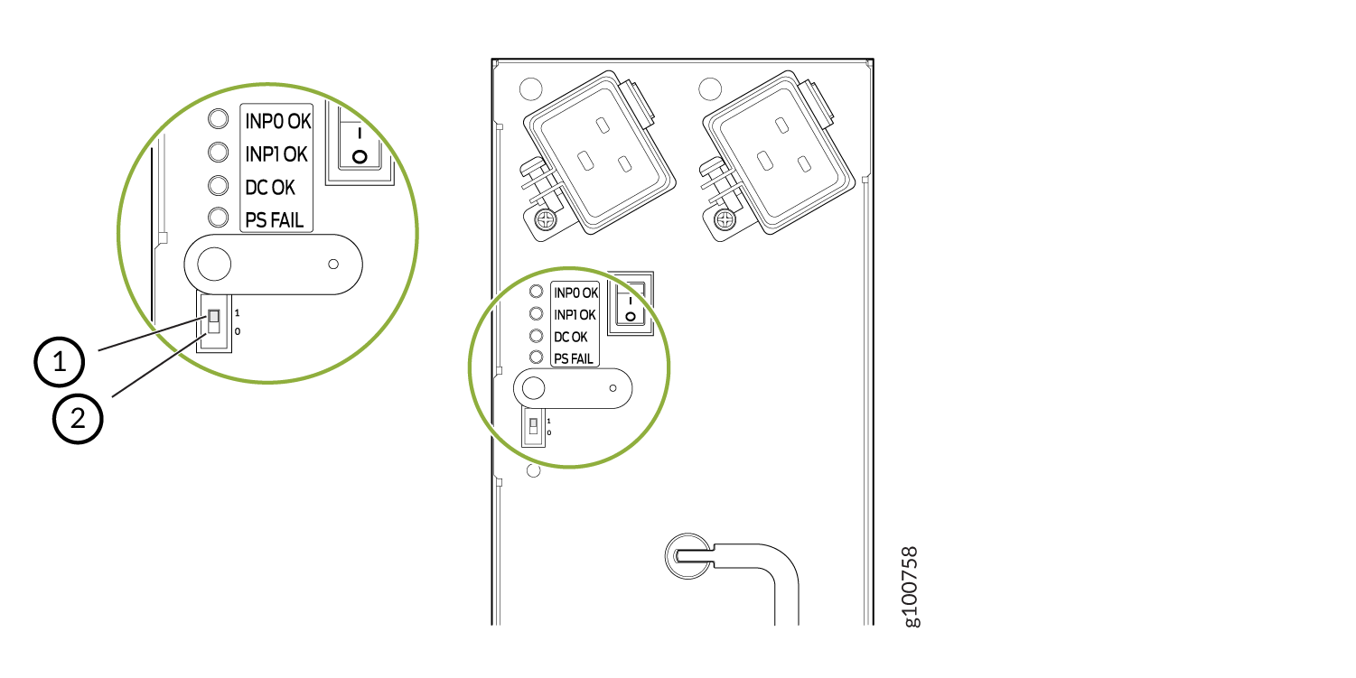
1 — Position 1 indicates two AC feeds are present | 2 — Position 0 indicates one AC feeds is present |
Use the show chassis power command to verify that the DIP switch settings on
the high-capacity AC power supplies are set to the correct position. Here are examples of the
command output:
Example 1: Proper setting of the DIP switch
user@host>show chassis power
PEM 0:
  State:     Online
  AC input:  OK (2 feed expected, 2 feed connected)
  Capacity:  5100 W (maximum 5100 W)
  DC output: 171 W (zone 0, 3 A at 57 V, 3% of capacity)

PEM 1:
  State:     Online
  AC input:  OK (2 feed expected, 2 feed connected)
  Capacity:  5100 W (maximum 5100 W)
  DC output: 342 W (zone 1, 6 A at 57 V, 6% of capacity)

PEM 2:
  State:     Online
  AC input:  OK (1 feed expected, 1 feed connected)
  Capacity:  2550 W (maximum 2550 W)
  DC output: 114 W (zone 0, 2 A at 57 V, 4% of capacity)

PEM 3:
  State:     Online
  AC input:  OK (2 feed expected, 2 feed connected)
  Capacity:  5100 W (maximum 5100 W)
  DC output: 399 W (zone 1, 7 A at 57 V, 7% of capacity)

System:
  Zone 0:
      Capacity:          5100 W (maximum 5100 W)
      Allocated power:   595 W (4505 W remaining)
      Actual usage:      285 W
  Zone 1:
      Capacity:          5100 W (maximum 5100 W)
      Allocated power:   1180 W (3920 W remaining)
      Actual usage:      741 W
  Total system capacity: 10200 W (maximum 10200 W)
  Total remaining power: 8425 W

root@cland03> show chassis alarms
No alarms currently active
In Example 1, PEM 0 is running at full capacity (5100 W) with two AC feeds expected and two AC feeds connected. This indicates that the DIP switch is properly set to Position 1 since two AC feeds are connected. The example also shows that PEM 2 is running at reduced capacity (2550 W) with one AC feed expected and one AC feed connected. This indicates that the DIP switch is correctly set to Position 0 since one feed is present.
Example 2 shows the show chassis power command output when the DIP switch is
set improperly:
Example 2: Improper Setting of the DIP Switch
user@host>show chassis power
PEM 0:
  State:     Online
  AC input:  OK (2 feed expected, 2 feed connected)
  Capacity:  5100 W (maximum 5100 W)
  DC output: 114 W (zone 0, 2 A at 57 V, 2% of capacity)

PEM 1:
  State:     Online
  AC input:  OK (2 feed expected, 2 feed connected)
  Capacity:  5100 W (maximum 5100 W)
  DC output: 342 W (zone 1, 6 A at 57 V, 6% of capacity)

PEM 2:
  State:     Present
  AC input:  Check (2 feed expected, 1 feed connected)
  Capacity:  2550 W (maximum 2550 W)
  DC output: 114 W (zone 0, 2 A at 57 V, 4% of capacity)

PEM 3:
  State:     Online
  AC input:  OK (2 feed expected, 2 feed connected)
  Capacity:  5100 W (maximum 5100 W)
  DC output: 399 W (zone 1, 7 A at 57 V, 7% of capacity)

System:
  Zone 0:
      Capacity:          5100 W (maximum 5100 W)
      Allocated power:   595 W (4505 W remaining)
      Actual usage:      228 W
  Zone 1:
      Capacity:          5100 W (maximum 5100 W)
      Allocated power:   1180 W (3920 W remaining)
      Actual usage:      741 W
  Total system capacity: 10200 W (maximum 10200 W)
  Total remaining power: 8425 W

root@cland03> show chassis alarms
1 alarms currently active
Alarm time               Class  Description
2021-10-27 13:15:14 PDT  Major  PEM 2 Not OK
The PEM 0 status indicates the system is Online, the
AC Input is OK, is running at full capacity (5100 W) with
two AC feeds expected and two AC feeds connected. But notice the status for PEM
2. The State is Present and the AC
input is Check (2 feed expected, 1 feed connected). This
indicates there is a mismatch between the DIP switch setting and the number of feeds
connected. Therefore, the power supply is running at reduced capacity (2550 W). If PEM 1
should be running at full-capacity, verify that there are two feeds connected to the power
supplies and the DIP switch is set to position 1.
AC Power Circuit Breaker Requirements for the SRX5800 Firewall
Each AC power supply has a single AC appliance inlet located in the chassis directly above the power supply that requires a dedicated AC power feed. We recommend that you use a dedicated customer site circuit breaker rated for 15 A (250 VAC) minimum for each AC power supply, or as required by local code.
Each high-capacity second-generation (MX960-PSM-5K-AC) power supply accepts two AC feeds in two unique AC receptacles. We recommend that you use a dedicated customer site circuit breaker rated for 38 A (264 VAC) minimum for each high-capacity second generation AC power supply, or as required by local code.
Each power cord feed must have a dedicated circuit breaker.
High-Voltage Second-Generation Universal (HVAC/HVDC) Power Supply for SRX5800 Firewall—MX960-PSM-HV
The SRX5800 can be powered by four high-voltage second-generation universal power supplies (MX960-PSM-HV). The MX960-PSM-HV supports high-voltage alternating current (HVAC), or high-voltage direct current (HVDC). The MX960-PSM-HV power supplies must be installed in adjacent slots in the chassis. The MX960-PSM-HV (HVAC/HVDC) power supply has one power inlet on front panel of the power supply rated at 30 A. The inlet requires a dedicated power feed and a dedicated breaker. For all power supplies the circuit breaker protection should be designed according to National Electrical Code (NEC) or any similar local standard based on maximum drawn current of the power supply specified in this document.
The MX960-PSM-HV (HVAC/HVDC) power supply configurations are zoned meaning that certain components in the SRX5800 chassis are powered by specific power supplies.
Figure 9 and Figure 10 illustrates MX960-PSM-HV (HVAC/HVDC) power supplies for the SRX5800.
Each MX960-PSM-HV (HVAC/HVDC) power supply provides output power of 5100 W. Each power supply has one receptacle, located on the power supply. Do not use the receptacle located on the chassis.
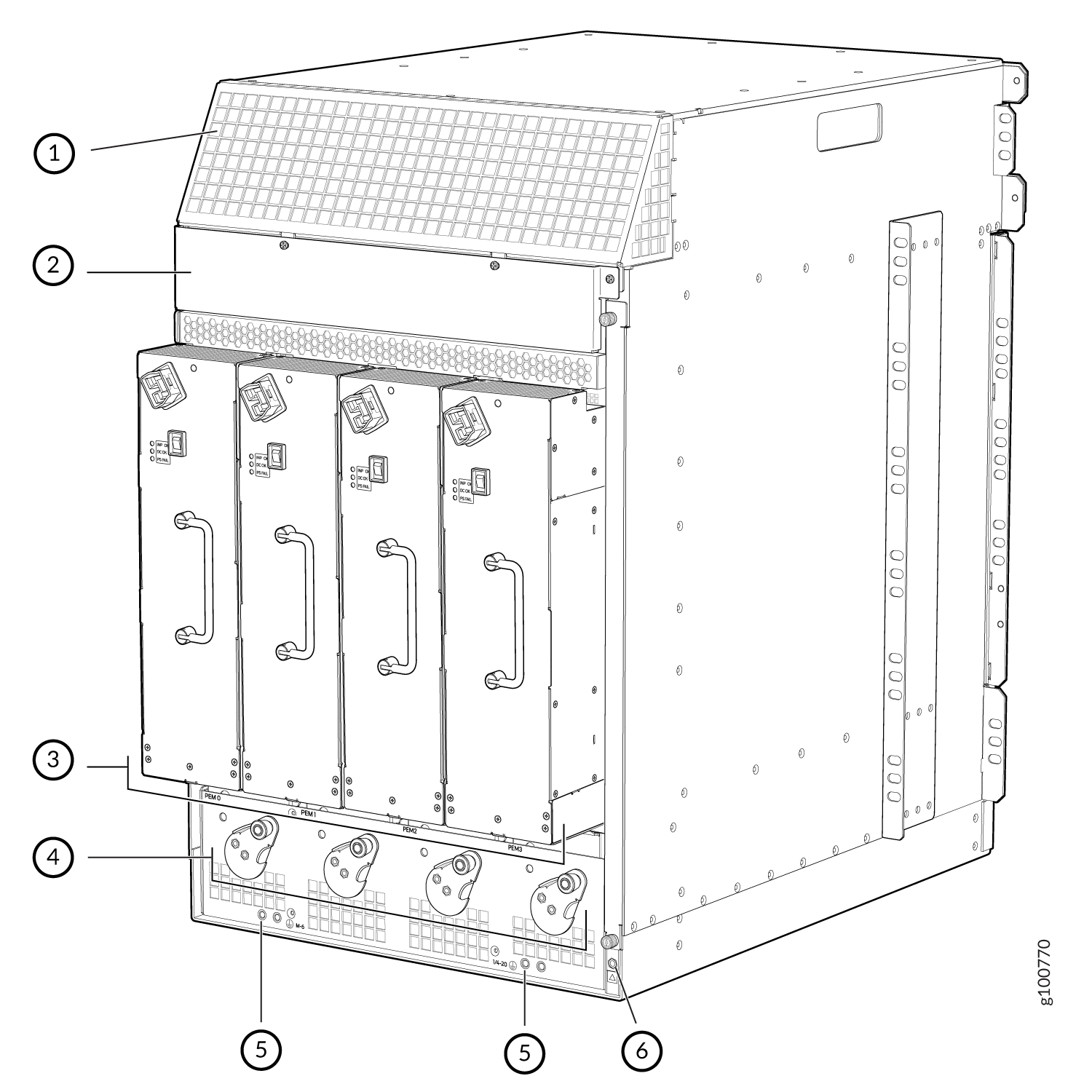
1 — Air exhaust | 4 — Power supply ejectors |
2 — Power distribution unit cover | 5 — Grounding points |
3 — Power supplies | 6 — ESD |
The minimum number of power supplies must be present in the router at all times. Refer to Table 12.
| Configuration | Minimum Required Number of Power Supplies | Model Number |
|
HVAC or HVDC |
One per zone x two zones = 2 power supplies |
MX960-PSM-HV |
High-Voltage Second-Generation Universal (HVAC/HVDC) Power Supply LEDs
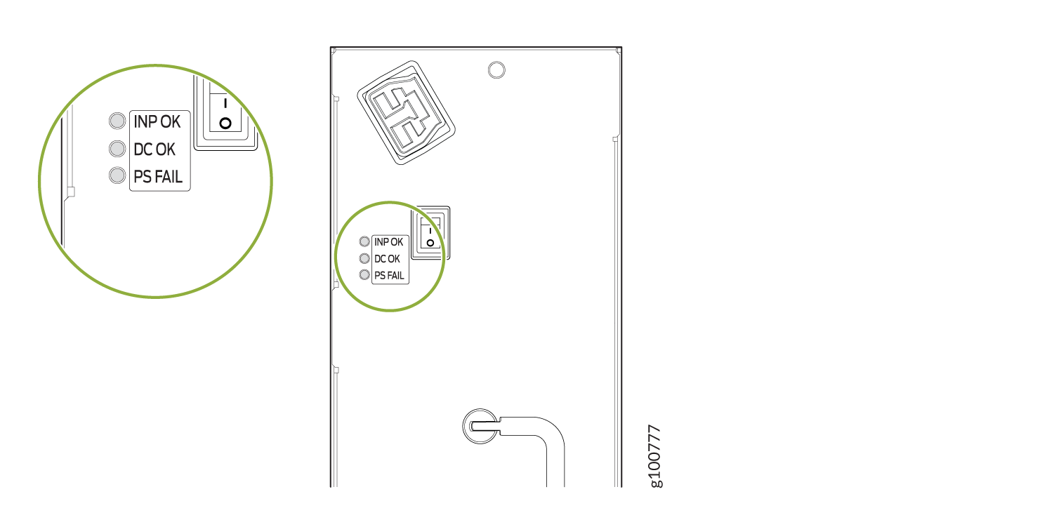
Each high-voltage second-generation universal (MX960-PSM-HV) power supply faceplate contains three LEDs that indicate the status of the power supply (see Figure 11). The power supply status is also reflected in two LEDs on the craft interface In addition, a power supply failure triggers the red alarm LED on the craft interface.
|
Label |
Color |
State |
Description |
|---|---|---|---|
|
INP OK |
Green |
Off |
AC power applied to power supply is not within the normal operating range. |
|
On |
AC power applied to power supply is within the normal operating range. |
||
|
DC OK |
Green |
Off |
DC power outputs generated by the power supply are not within the normal operating ranges. |
|
On |
DC power outputs generated by the power supply are within the normal operating ranges. |
||
|
PS FAIL |
Red |
Off |
Power supply is functioning normally. |
|
On |
Power supply is not functioning normally. Check AC OK and DC OK LEDs for more information. |
High-Voltage Second-Generation Universal (HVAC/HVDC) Power Supply Specifications for the SRX5800 Firewall
Table 14 lists the MX960-PSM-HV (HVAC or HVDC) power supply electrical specifications.
|
Item |
Specification |
|
|---|---|---|
| HVAC/HVDC Power Supply | ||
|
Maximum output power |
5100 W |
|
|
AC nominal input voltage |
Operating range: 200-305 VAC |
|
|
DC nominal input voltage |
200-410 VDC |
|
|
AC input current rating |
30 A maximum |
|
|
DC input current rating |
30 A maximum |
|
|
Maximum AC inrush current |
70 A @ 264 VAC |
|
|
Maximum DC inrush current |
70 A @ 410 VDC |
|
|
Item |
High-voltage Second-Generation Universal Power Supply |
|---|---|
|
Redundancy |
2+2 |
|
Output power (maximum) per supply |
5100 W |
High-Voltage Second-Generation Universal (HVAC/HVDC) Power Cord Specifications for the SRX5800 Firewall
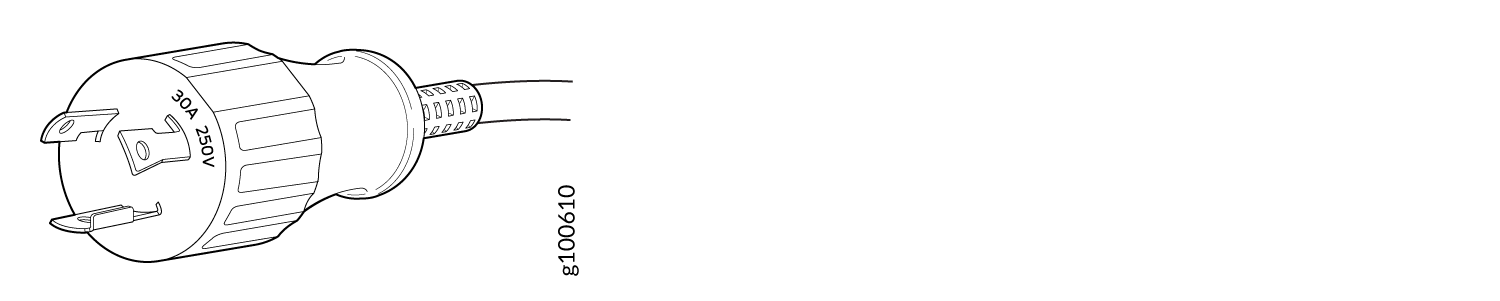
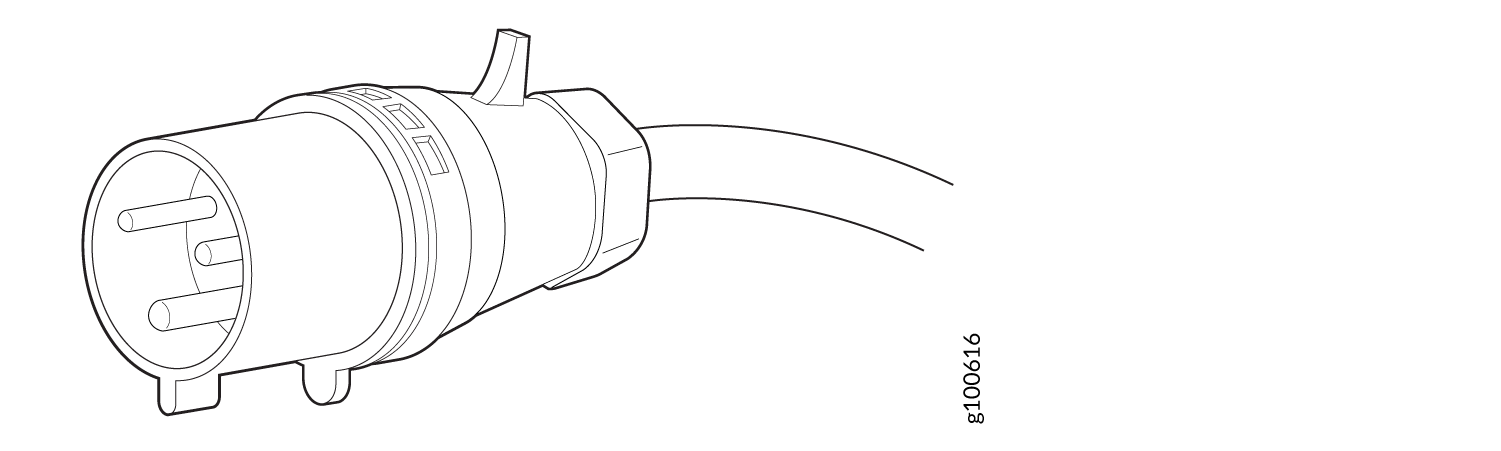
The MX960-PSM-HV (HVAC or HVDC) power supplies requires a high current cable assembly when set for 30-A input. One end of the cable has an Anderson APP-400 connector, the other end of the cable is bare wire. See Figure 12 and Table 15. These cables are separately orderable and are not shipped automatically with MX960-PSM-HV orders. An example of the right-angle cable and connector is shown in Figure 14. For connection to AC systems, Juniper provides a cable with either a NEMA 30-A connector (Figure 12) or an IEC 330P6W connector (Figure 13).
The MX960-PSM-HV (HVAC or HVDC) power supply has one C20 receptacles on front panel of the power supply. The cover needs to be installed to cover C20 receptacles on PDM on top of the chassis. Input receptacle is APP 2007G type from Anderson rated 30 A 400V.
The high voltage alternating current (HVAC), and high voltage direct current (HVDC) have specific cord requirements. Table 15 provides specifications and plug standards on the power cord provided for each country or region.
The bend radius for the power cord cables is 7 inches. Avoid bending the cable beyond its bend radius when dressing the cables into the cable channels on the rack.
|
Spare Juniper Model Number |
Locale |
Cord Set Rating |
Connector |
|---|---|---|---|
|
CBL-PWR2-332P6W-RA |
Continental Europe AC power cord |
30-A 250 VAC |
Anderson/right-angle to IEC 332P6 |
|
CBL-PWR2-BARE-RA |
North America HVAC/HVDC power cord |
30-A, 400 VAC |
Anderson/right-angle to bare wire |
|
CBL-PWR-SG4-RA |
U.S.A |
30-A, 400 VAC |
SAF-D-GRID 400 right-angle (LH) |
|
CBL-PWR-SG4 |
North America AC jumper power cord |
30-A, 400 VAC |
SAF-D-GRID 400 right-angle (LH) |
|
CBL-PWR2-BARE |
North America HVAC/HVDC power cord |
30- A, 400 VAC |
Anderson/straight to bare wire |
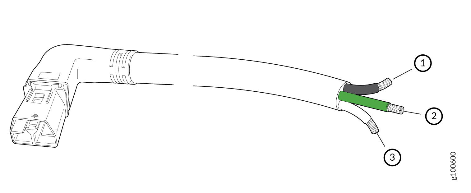
1 — Black wire–Positive (+) | 3 — White wire–Negative |
2 — Green wire-Ground |
The AC power cord for the router is intended for use with the router only and not for any other use.
Translation from Japanese: The attached power cable is only for this product. Do not use the cable for another product.
In North America, AC power cords must not exceed 4.5 m (approximately 14.75 ft) in length, to comply with National Electrical Code (NEC) Sections 400-8 (NFPA 75, 5-2.2) and 210-52, and Canadian Electrical Code (CEC) Section 4-010(3). You can order AC power cords that are in compliance.
The router is a pluggable type A equipment installed in restricted access location. It has a separate protective earthing terminal (Metric [–M6] and English [–¼-20] screw ground lugs) provided on the chassis in addition to the grounding pin of the power supply cord. This separate protective earth terminal must be permanently connected to earth.
Power cords and cables must not block access to device components or drape where people could trip on them.
High-Voltage Second-Generation Universal (HVAC/HVDC) Power Circuit Breaker Requirements for the SRX5800 Firewall
The circuit breaker protection on all the power supplies should be designed according to National Electrical Code (NEC) of country of system installation or any similar local standard based on maximum drawn current of the power supply specified in this document.
Each high-voltage universal (MX960-PSM-HV) power supply has a single feed. The input AC or DC receptacle inlet is located on front panel of the power supply.
Each power cord feed should have dedicated circuit breakers. We recommend that size of the circuit breaker protection should be designed according to National Electrical Code (NEC) of country of system installation or any similar local standard based on maximum drawn current of the power supply specified in this document.
Use a 2-pole circuit breaker rated at minimum of 125% of the rated current per NEC or as local codes.
Primary Overcurrent Protection by the Building Circuit Breaker. This breaker must protect against excess current, short circuit, and earth grounding fault in accordance with NEC which is ANSI/NFPA 70.
SRX5800 Firewall Standard-Capacity DC Power Supply—SRX5800-PWR-DC
In the DC power configuration, the firewall contains either two or four DC power supplies (see Figure 15), located at the lower rear of the chassis in slots PEM0 through PEM3 (left to right). You can upgrade your DC power system from two to four power supplies.
Four power supplies provide full redundancy. If a DC power supply fails, its redundant power supply takes over without interruption.
Each DC power supply has a single DC input (–48 VDC and return) that requires a dedicated 80 A (–48 VDC) circuit breaker for the maximum hardware configuration.
SRX5800 Firewall Standard-Capacity DC Power Supply LEDs
Each standard-capacity DC power supply faceplate contains three LEDs that indicate the status of the power supply (see Table 16). The power supply status is also reflected in two LEDs on the craft interface. In addition, a power supply failure triggers the red alarm LED on the craft interface.
Label |
Color |
State |
Description |
|---|---|---|---|
PWR OK |
Green |
Off |
Power supply is not functioning normally. Check the INPUT OK LED for more information. |
On |
Power supply is functioning normally. |
||
BREAKER ON |
Green |
Off |
DC power supply circuit breaker is turned off. |
On |
DC power supply circuit breaker is turned on. |
||
INPUT OK |
Green |
Off |
DC input to the PEM is not present. |
On |
DC input is present, and is connected in correct polarity. |
||
Amber |
On |
DC input is present, but connected in reverse polarity. |
SRX5800 Firewall High-Capacity DC Power Supply—SRX5800-HPWR-DC
High-capacity DC power supplies (SRX5800-HPWR-DC) provide a maximum of 4100 W of power each. Two high-capacity DC power supplies are required, and you can install four high-capacity DC power supplies for redundancy. Each high-capacity DC power supply has inlets for two DC power feeds. The four power connectors (-48V and RTN for each of the two inlets) are located behind a clear plastic cover near the bottom of the power supply. Each DC power inlet you use requires a dedicated DC power feed and a dedicated 80 A circuit breaker. See Figure 16.
The firewall cannot be powered from standard-capacity and high-capacity DC power supplies simultaneously. The one exception is during the process of replacing standard-capacity DC power supplies with high-capacity DC power supplies, when it is permissible to have both types installed briefly.
The high-capacity power supply will operate with only one of its two DC inlets connected to a DC power feed. However, its DC output will be limited to a maximum of 1700 W. We recommend that you connect two DC power feeds to each high-capacity DC power supply.
The firewall must be running Junos OS Release 12.1X44-D10 or later in order to use high-capacity DC power supplies.
Each high-capacity DC power supply has an input mode switch, covered by a small metal plate. The input mode switch tells the system the number of DC power feeds it should expect. The input mode switch settings are described in Table 17. The default setting is 1.
|
Mode Switch Setting |
DC Inputs |
Result |
|---|---|---|
|
1 |
Both DC inlets powered |
DC output of 4100 W DC OK LED lights |
|
Only one DC inlet powered |
DC output of 1700 W DC OK LED unlit |
|
|
0 |
Both DC inlets powered |
DC output of 1700 W DC OK LED lights |
|
Only one DC inlet powered |
DC output of 1700 W DC OK LED lights |
We recommend that you set the input mode switch to 1 and connect two DC input feeds to each high-capacity DC power supply.
To meet safety and electromagnetic interference (EMI) requirements and to ensure proper operation, the firewall chassis must be adequately grounded before power is connected. See Grounding the SRX5800 Firewall for instructions.
SRX5800 Firewall High-Capacity DC Power Supply LEDs
Each high-capacity DC power supply faceplate contains four LEDs that indicate the status of the power supply (see Table 18). The power supply status is also reflected in two LEDs on the craft interface. In addition, a power supply failure triggers the red alarm LED on the craft interface.
Label |
Color |
State |
Description |
|---|---|---|---|
INP0 OK |
Green |
Off |
DC power applied to the power supply at input INP0 is not within the normal operating range. |
On |
DC power applied to the power supply at input INP0 is within the normal operating range. |
||
INP1 OK |
Green |
Off |
DC power applied to the power supply at input INP1 is not within the normal operating range. |
On |
DC power applied to the power supply at input INP1 is within the normal operating range. |
||
DC OK |
Green |
Off |
DC power outputs generated by the power supply are not within the normal operating ranges. |
On |
DC power outputs generated by the power supply are within the normal operating ranges. |
||
PS FAIL |
Red |
Off |
Power supply is functioning normally. |
On |
Power supply is not functioning normally. Check the INP0 OK, INP1 OK, and DC OK LEDs for more information. |
SRX5800 Firewall DC Power Supply Specifications
Table 19 lists the DC power supply electrical specifications.
Item |
Standard-Capacity |
High-Capacity |
|
|---|---|---|---|
Two-Feed Mode |
One-Feed Mode |
||
Maximum output power |
2800 W |
4100 W |
1700 W |
DC input voltage |
Nominal: –48 VDC Operating range: –40 to –72 VDC |
Nominal: –48 VDC Operating range: –40 to –72 VDC |
Nominal: –48 VDC Operating range: –40 to –72 VDC |
Maximum input current rating @ 40 VDC |
70 A |
128 A for both feeds (66 A and 62 A per feed) |
52 A |
DC nominal input current rating @48 VDC |
58 A maximum@–48 VDC (nominal) |
104 A for both feeds (54 A and 50 A per feed) |
42 A |
Efficiency |
99% |
86% |
|
Note:
This value is at full load and nominal voltage. |
|||
Internal Circuit Breaker |
80 A |
– |
– |
Table 20 lists the power system electrical specifications.
Item |
Normal-Capacity |
High-Capacity |
|
|---|---|---|---|
Redundancy |
2+2 |
2+2 |
|
Output power (maximum) per supply |
2800 W |
Two-feed mode |
One-feed mode |
4100 W |
1700 W |
||
Output power (maximum) per system |
5600 W |
8200 W |
3400 W |
DC Power Cable Specifications for the SRX5800 Firewall
Table 21 summarizes the specifications for the power cables, which you must supply.
Cable Type |
Quantity |
Specification |
|---|---|---|
Power |
Four 6-AWG (13.3 mm2) cables for each power supply |
Minimum 60°C wire, or as required by the local code |
You must ensure that power connections maintain the proper polarity. The power source cables might be labeled (+) and (–) to indicate their polarity. There is no standard color coding for DC power cables. The color coding used by the external DC power source at your site determines the color coding for the leads on the power cables that attach to the terminal studs on each power supply.
DC Power Cable Lug Specifications for the SRX5800 Firewall
The accessory box shipped with the firewall includes the cable lugs that attach to the terminal studs of each power supply (see Figure 17).
Before firewall installation begins, a licensed electrician must attach a cable lug to the grounding and power cables that you supply. A cable with an incorrectly attached lug can damage the firewall.
The firewall is a pluggable type A equipment installed in restricted access location. It has a separate protective earthing terminal [Metric -M6 and English - ¼-20 screw) ground lugs] provided on the chassis. This separate protective earth terminal must be permanently connected to earth.
DC Power Circuit Breaker Requirements for the SRX5800 Firewall
If you plan to operate a maximally configured DC-powered firewall with standard-capacity power supplies, we recommend that you provision at least 116 A (58 A per feed) @ –48 VDC (nominal) for the system. Use a customer site circuit breaker rated according to respective National Electrical Code and customer site internal standards to maintain proper level of protection for the current specified above.
If you plan to operate a maximally configured DC-powered firewall with high-capacity power supplies, we recommend that you provision at least 208 A (104 A per supply) @ –48 VDC (nominal) for the system. This is maximum current draw at –48 VDC when two power supplies are providing the power to the system and the redundant power supplies are not supplying power or not present. Use a customer site circuit breaker rated according to respective National Electrical Code and customer site internal standards to maintain proper level of protection for the current specified above.
If you plan to operate a DC-powered firewall at less than the maximum configuration, we recommend that you provision a circuit breaker according to respective National Electrical Code and customer site internal standards to maintain proper level of protection for the current specified above or each DC power supply rated for at least 125% of the continuous current that the system draws at –48 VDC.
DC Power Source Cabling for the SRX5800 Firewall
Figure 18 shows a typical DC source cabling arrangement.
The DC power supplies in slots PEM0 and PEM1 must be powered by dedicated power feeds derived from feed A, and the DC power supplies in slots PEM2 and PEM3 must be powered by dedicated power feeds derived from feed B. This configuration provides the commonly deployed A/B feed redundancy for the system.
You must ensure that power connections maintain the proper polarity. The power source cables might be labeled (+) and (–) to indicate their polarity. There is no standard color coding for DC power cables. The color coding used by the external DC power source at your site determines the color coding for the leads on the power cables that attach to the terminal studs on each power supply.
For field-wiring connections, use copper conductors only.
Power cords and cables must not block access to device components or drape where people could trip on them.
SRX5800 Firewall Chassis Grounding Point Specifications
To meet safety and electromagnetic interference (EMI) requirements and to ensure proper operation, you must properly ground the firewall chassis before connecting power. See Grounding the SRX5800 Firewall for instructions.
Before firewall installation begins, a licensed electrician must attach cable lugs to the grounding and power cables that you supply. A cable with an incorrectly attached lug can damage the firewall.
The firewall chassis has two grounding points along the lower edge of the back panel. Each grounding point consists of two threaded holes spaced 0.625-in. (15.86-mm) apart (see Figure 19). The left grounding point fits M6 screws (European), and the right grounding point fits UNC 1/4–20 screws (American). The accessory box shipped with the firewall includes the cable lug that attaches to the grounding cable and two UNC 1/4–20 screws used to secure the grounding cable to the right-side grounding point on the firewall.
To ground the firewall, you must connect a grounding cable to earth ground and then attach it to the chassis grounding point using the two screws provided.
Additional grounding is provided to an AC-powered firewall when you plug its power supplies into grounded AC power receptacles.
SRX5800 Firewall Grounding Cable Specifications
The grounding cable that you provide must meet the specifications in Table 22.
Cable Type |
Quantity and Specification |
|---|---|
Grounding |
One 6-AWG (13.3 mm2), minimum 60°C wire, or as required by the local code |
To meet safety and electromagnetic interference (EMI) requirements and to ensure proper operation, you must properly ground the firewall chassis before connecting power. See Grounding the SRX5800 Firewall for instructions.
SRX5800 Firewall Grounding-Cable Lug Specification
The accessory box shipped with the firewall includes the cable lug that attaches to the grounding cable (see Figure 20) and two UNC 1/4–20 screws used to secure the grounding cable to the grounding points.
Before firewall installation begins, a licensed electrician must attach a cable lug to the grounding and power cables that you supply. A cable with an incorrectly attached lug can damage the firewall.
The same cable lug is used for the DC power cables.