Connecting the SRX5800 to Power
Tools and Parts Required for SRX5800 Firewall Grounding and Power Connections
To ground and provide power to the firewall, you need the following tools and parts:
Phillips (+) screwdrivers, numbers 1 and 2
2.5-mm flat-blade (–) screwdriver
7/16-in. hexagonal-head external drive socket wrench, or nut driver, with a torque range between 23 lb-in. (2.6 Nm) and 25 lb-in. (2.8 Nm) tightening torque, for tightening nuts to terminal studs on each power supply on a DC-powered firewall.
Wire cutters
Electrostatic discharge (ESD) grounding wrist strap
Grounding the SRX5800 Firewall
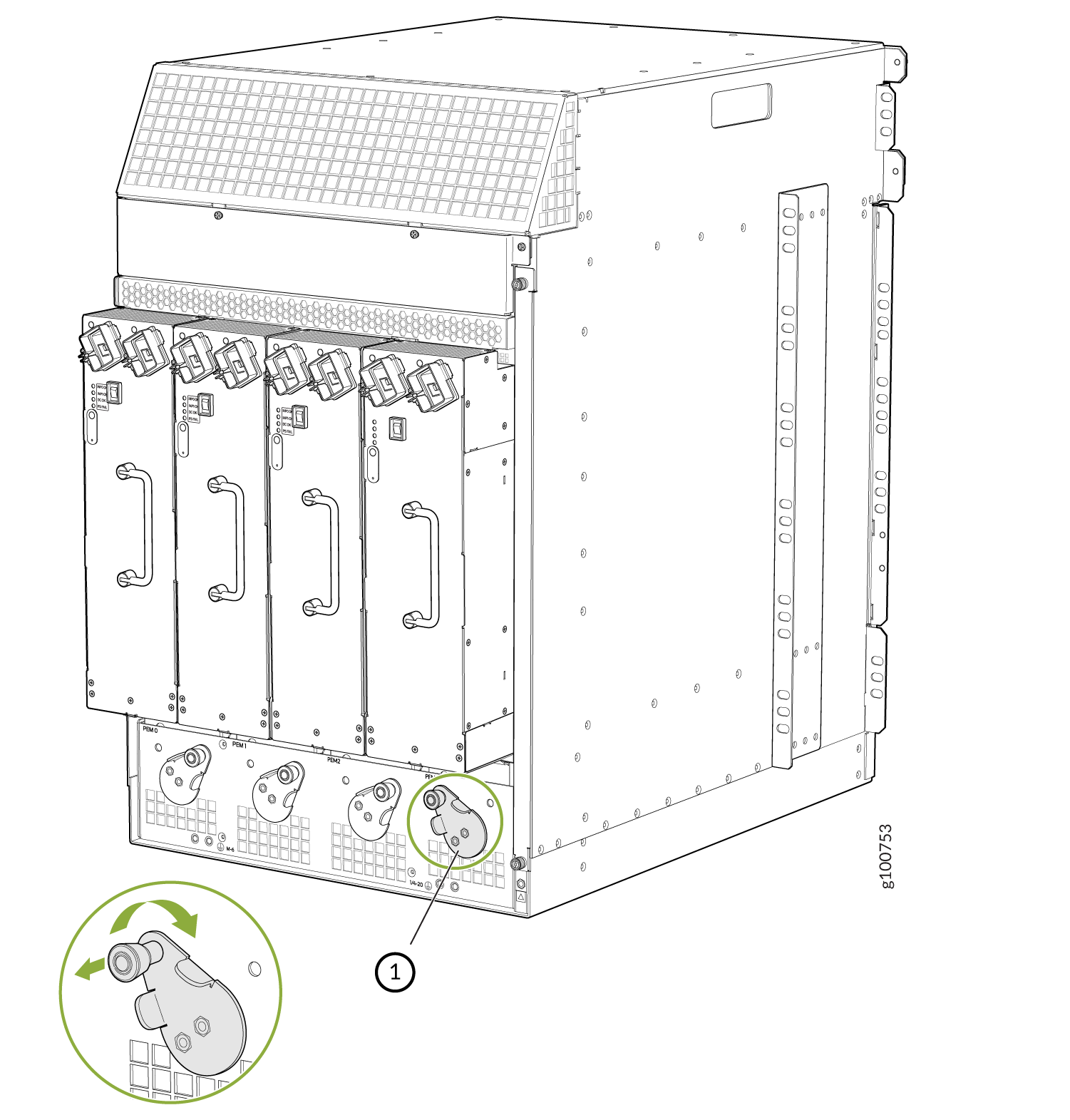
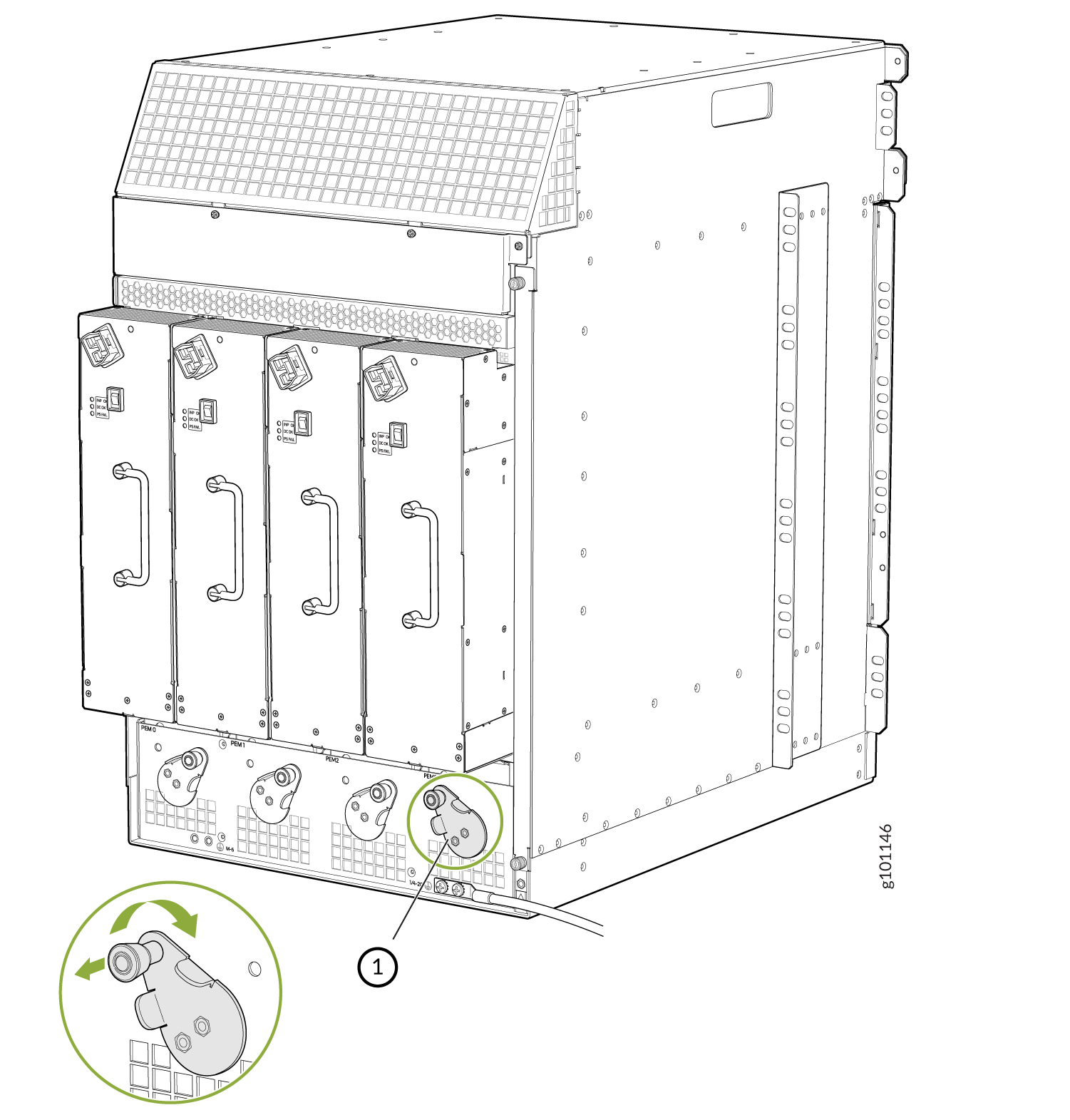
To meet safety and electromagnetic interference (EMI) requirements and to ensure proper operation, you must properly ground the firewall chassis before connecting power. You must install the SRX8500 device in a restricted-access location and ensure that the chassis is always properly grounded. The SRX5800 device has a two-hole protective grounding terminal provided on the chassis. See Figure 1. Under all circumstances, use this grounding connection to ground the chassis. For AC-powered systems, you must also use the grounding wire in the AC power cord along with the two-hole grounding lug connection. This tested system meets or exceeds all applicable EMC regulatory requirements with the two-hole protective grounding terminal.
You ground the firewall by connecting a grounding cable to earth ground and then attaching it to one of the chassis grounding points using two screws. You must provide the grounding cable (the cable lug is supplied with the firewall).
-
Secure the grounding cable lug to the
grounding point, first with the washers, and then
with the screws as shown in Figure 1.
Figure 1: Connecting the Grounding Cable
Connecting Power to an AC-Powered SRX5800 Firewall
To meet safety and electromagnetic interference (EMI) requirements and to ensure proper operation, you must properly ground the firewall chassis before connecting power. See Grounding the SRX5800 Firewall for instructions.
Do not mix AC and DC power supplies within the same firewall. Damage to the firewall might occur.
You connect AC power to the device by attaching power cords from the AC power sources to the AC appliance inlets located on the chassis above the power supplies. If the firewall is powered by high-capacity power supplies, you also connect AC feeds to AC appliance inlets located on the power supplies themselves. The power cords are not provided with the firewall; you must order them separately.
To connect the AC power cords to the firewall (see Figure 2 and Figure 3):
Connect Power to an SRX5800 Firewall with High-Capacity Second-Generation Power Supplies
A minimum of two AC nominal 220 VAC 20 amp power cords are required for this procedure.
-
Ensure that the release lever below the empty power supply slot is locked in the
counterclockwise position (see Figure 4).
Figure 4: SRX5800 Firewall with High-Capacity Second Generation AC Power Supplies Installed
If necessary, pull the spring-loaded locking pin in the release lever away from the chassis and turn the release lever counterclockwise until it stops. Let go of the locking pin in the release lever. Ensure that the pin is seated inside the corresponding hole in the chassis.
-
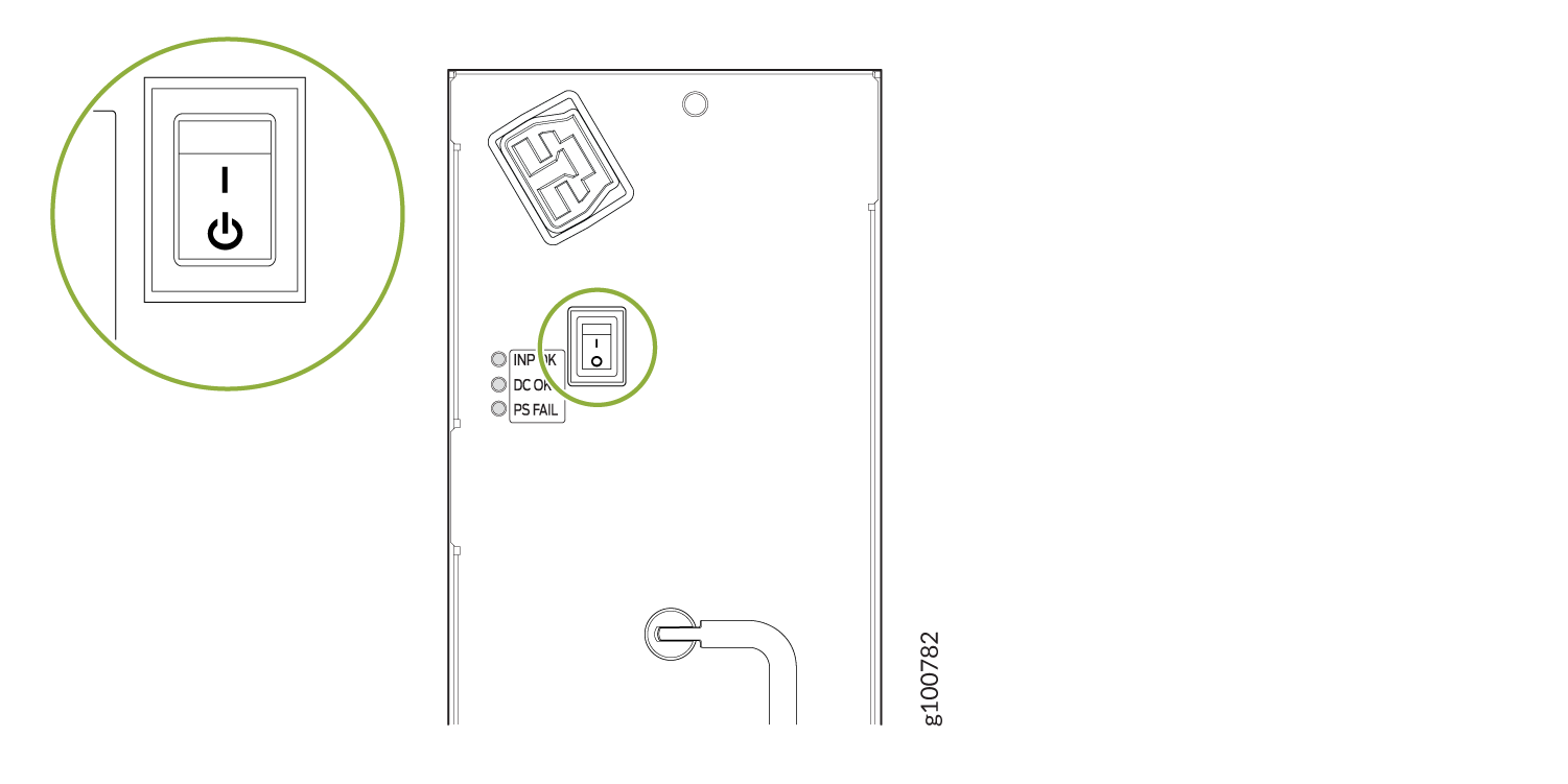
Move the input mode switch to position 0 if you plan to connect one feed, or position 1
if you plan to connect two feeds (see Figure 5).
Figure 5: SRX5800 High-Capacity Second-Generation AC Power Input Mode Switch
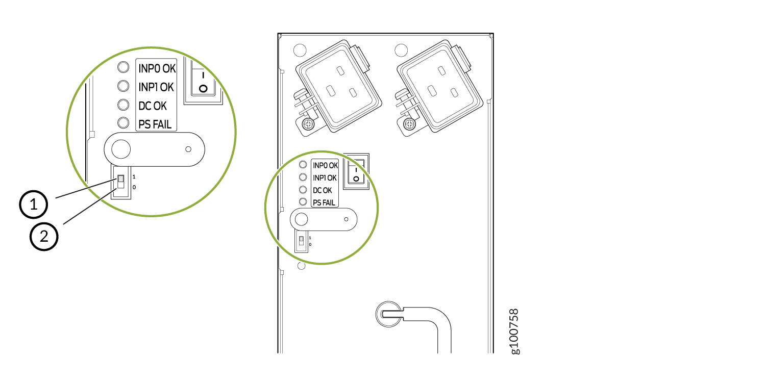 1—
1—1 (if you connect two feeds)
2—0 (if you connect one feed)
CAUTION:Do not use a pencil, because fragments can break off and cause damage to the power supply.
-
Plug the power cord into the corresponding appliance inlet located in the chassis
directly on the power supply. If using the power supply in two-feed mode, plug the second
power cord into the receptacle on the power supply.
Using a screwdriver, tighten the screw on the retainer to prevent the AC cord from getting lose. See Figure 6.
Note:Each power supply must be connected to a dedicated AC power feed and a dedicated customer site circuit breaker.
Note:To use high-capacity second-generation AC power supplies with full capacity you have to switch them to two feed mode and use two power cords per power supply. See Figure 6.
Figure 6: SRX5800 with One High-Capacity Second-Generation AC Power Feed Connected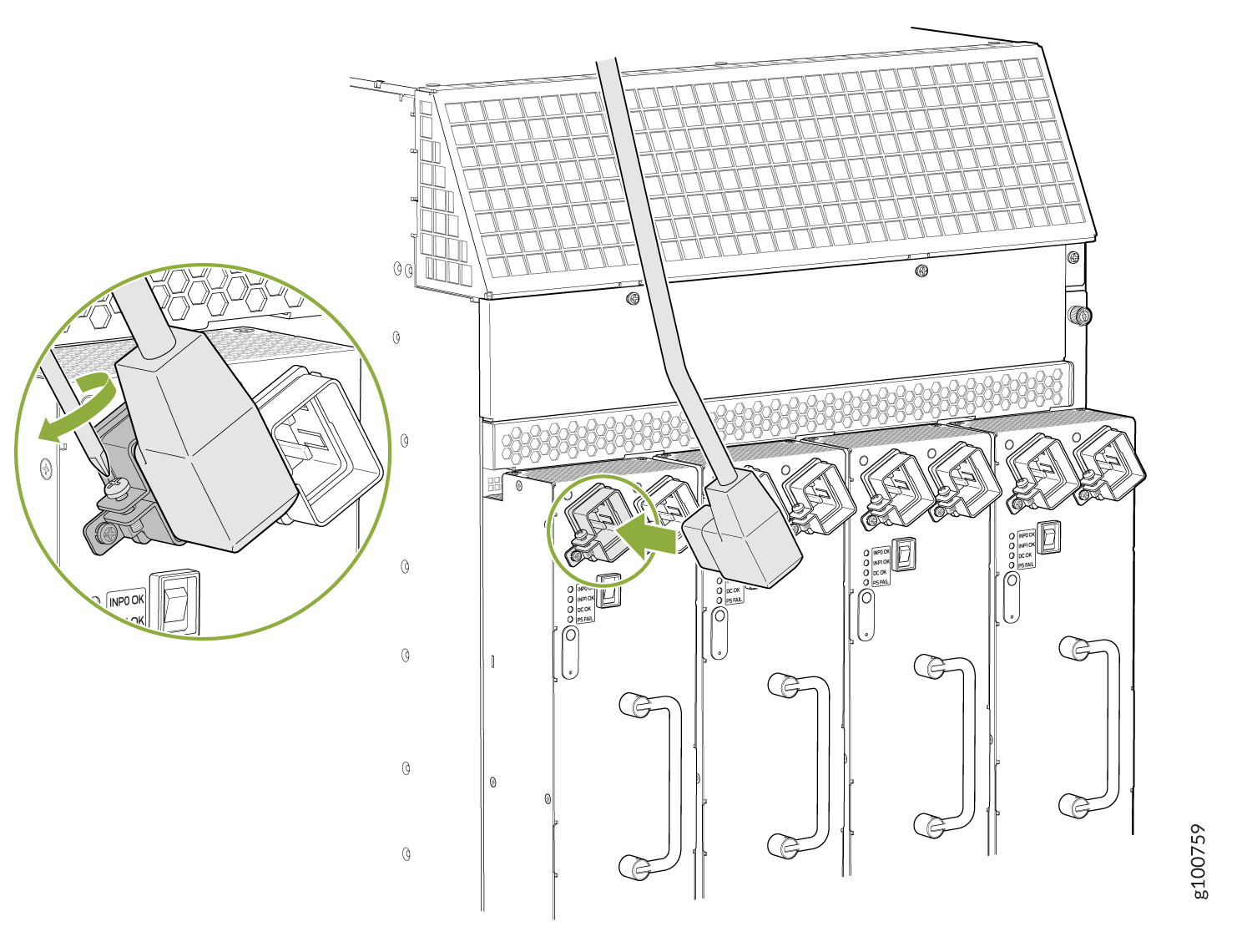 Figure 7: SRX5800 with Both High-Capacity Second-Generation AC Power Feeds Connected
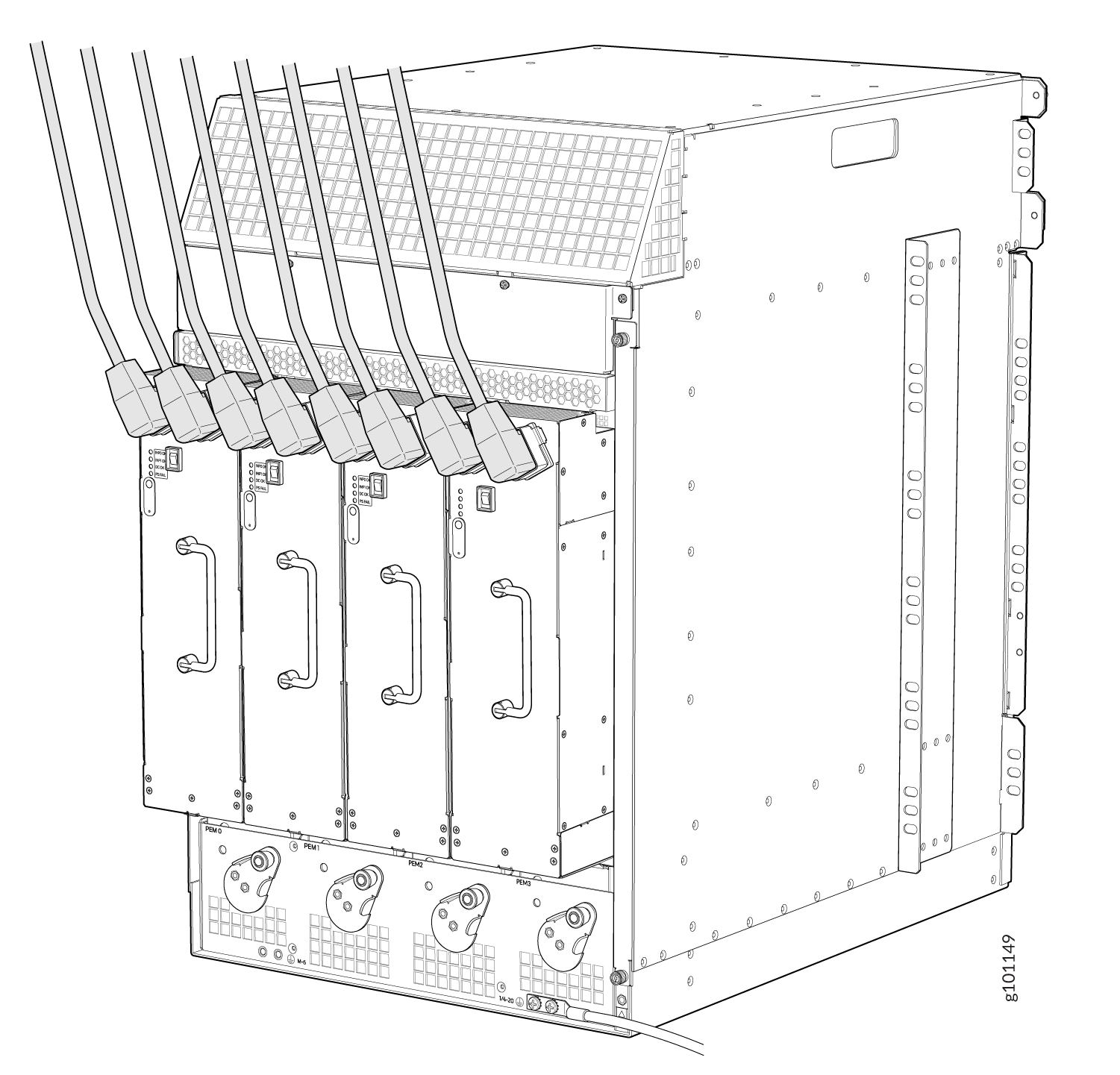
-
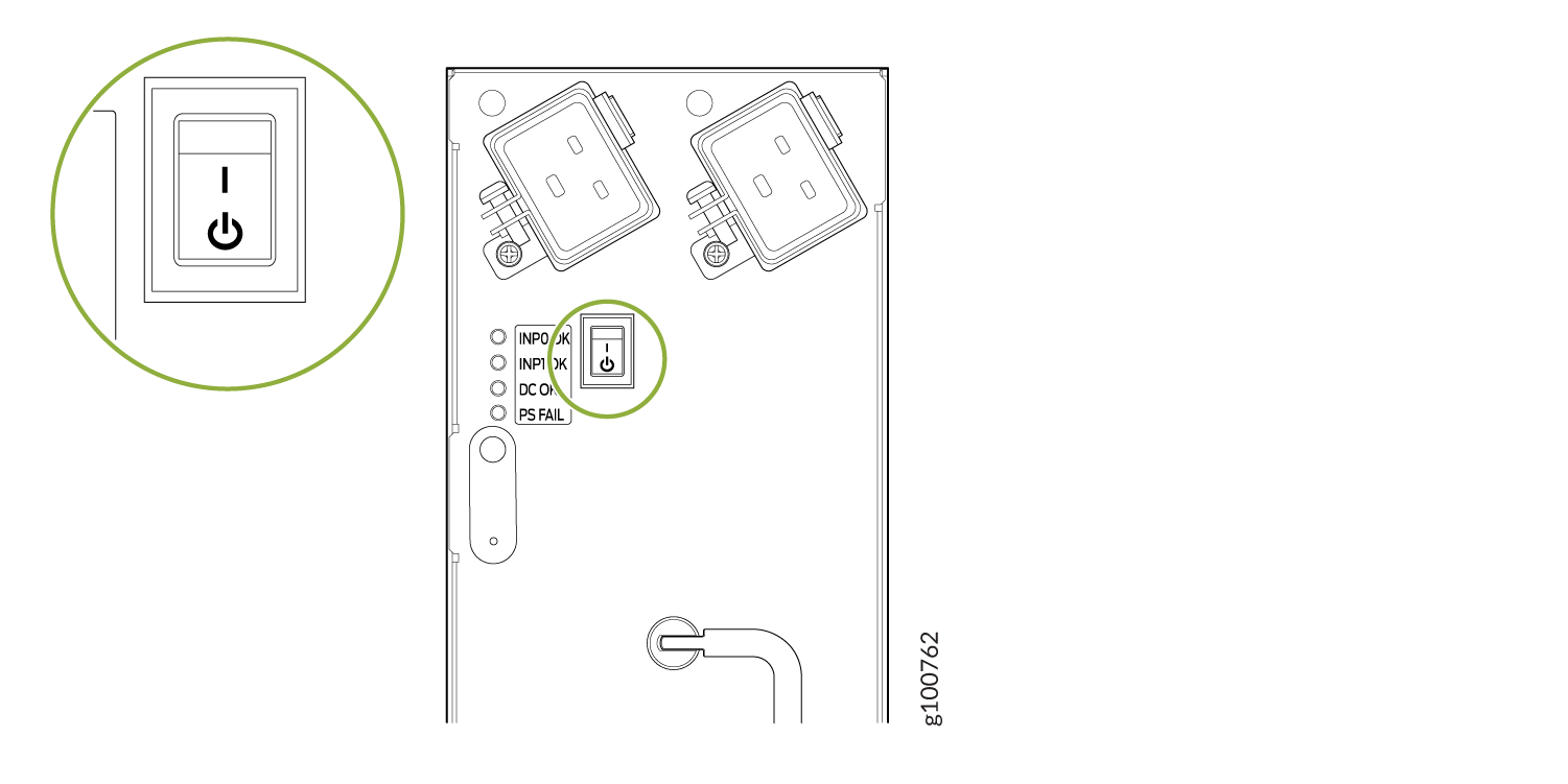
Move the AC input switch above the power supply to the on (—)
position. See Figure 8. This is the only switch you have to turn on.
Figure 8: SRX5800 with High-Capacity Second-Generation AC Power Supplies Input Switch
Powering On an AC-Powered SRX5800 Firewall
To power on an AC-powered firewall:
Connect Power to an SRX5800 Firewall with High-Voltage Second-Generation Universal (HVAC/HVDC) Power Supplies
To install and power on an High-Voltage Second-Generation Universal (HVAC/HVDC) power supply, use the following procedure.
-
Ensure that the release lever below the empty power supply slot is locked in the
counterclockwise position (see Figure 9).
Figure 9: SRX5800 Firewall with High-Voltage Second-Generation Universal (HVAC or HVDC) Installed
If necessary, pull the spring-loaded locking pin in the release lever away from the chassis and turn the release lever counterclockwise until it stops. Let go of the locking pin in the release lever. Ensure that the pin is seated inside the corresponding hole in the chassis.
-
Plug the power cord into the corresponding appliance inlet located in the chassis
directly on the power supply.
Note:
Each power supply must be connected to a dedicated power feed and a dedicated customer site circuit breaker.
Figure 10: SRX5800 Firewall with One High-Voltage Second-Generation (HVAC or HVDC) Power Feed Connected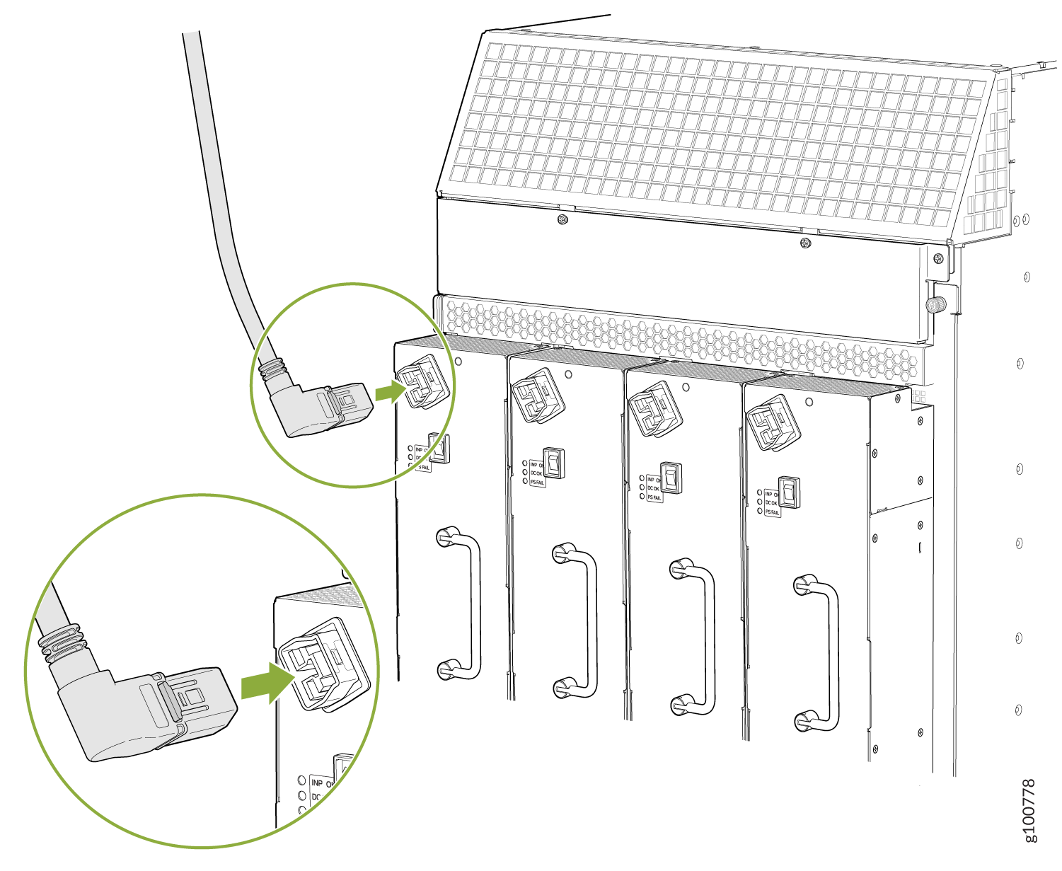
-
Move the input switch above the power supply to the on (—)
position.
Figure 11: High-Voltage Second-Generation (HVAC or HVDC)MX960 AC Power Input Mode Switch
Connecting Power to a DC-Powered SRX5800 Firewall
Before you perform DC power procedures, ensure there is no power to the DC circuit. To ensure that all power is off, locate the circuit breaker on the panel board that services the DC circuit, switch the circuit breaker to the off position, and tape the switch handle of the circuit breaker in the off position.
To meet safety and electromagnetic interference (EMI) requirements and to ensure proper operation, you must properly ground the firewall chassis before connecting power. See Grounding the SRX5800 Firewall for instructions.
Do not mix AC and DC power supplies within the same firewall. Damage to the firewall might occur.
You connect DC power to the firewall by attaching power cables from the external DC power sources to the terminal studs on the power supply faceplates. You must provide the power cables (the cable lugs are supplied with the firewall).
To connect the DC source power cables to the firewall:
-
Install heat-shrink tubing insulation around the power cables.
To install heat-shrink tubing:
-
Slide the tubing over the portion of the cable where it is attached to the lug barrel. Ensure that tubing covers the end of the wire and the barrel of the lug attached to it.
-
Shrink the tubing with a heat gun. Ensure that you heat all sides of the tubing evenly so that it shrinks around the cable tightly.
Figure 12 shows the steps to install heat-shrink tubing.
Note:Do not overheat the tubing.
Figure 12: How to Install Heat-Shrink Tubing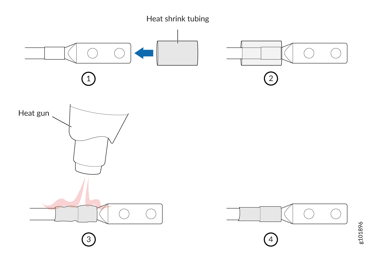
-
Powering On a DC-Powered SRX5800 Firewall
To power on a DC-powered firewall:
Powering Off the SRX5800 Firewall
After powering off a power supply, wait at least 60 seconds before turning it back on.
To power off the firewall: