Unpacking and Mounting the SRX345
Unpacking the SRX345 Firewall
Ensure that you have the following parts and tools available:
Phillips (+) screwdriver, number 2
Blank panels to cover any slots not occupied by a component
The SRX345 Firewall is shipped in a cardboard carton and secured with foam packing material. The carton also contains an accessory box and quick start instructions.
The services gateway is maximally protected inside the cardboard carton. Do not unpack it until you are ready to begin installation.
To unpack the SRX345 Firewall:
- Move the cardboard carton to a staging area as close to the installation site as possible, where you have enough room to remove the components from the chassis.
- Position the cardboard carton with the arrows pointing up.
- Carefully open the top of the cardboard carton.
- Remove the foam covering the top of the services gateway.
- Remove the accessory box.
- Verify the parts received against the lists in Verifying Parts Received with the SRX345 Services Gateway.
- Store the brackets and bolts inside the accessory box.
- Save the shipping carton and packing materials in case you need to move or ship the services gateway at a later time.
Verifying Parts Received with the SRX345 Firewall
The SRX345 Firewall shipment package contains a packing list. Check the parts in the shipment against the items on the packing list. The packing list specifies the part numbers and carries a brief description of each part in your order.
If any part on the packing list is missing, contact your customer service representative or contact Juniper customer care from within the U.S. or Canada by telephone at 1-888-314-5822. For international-dial or direct-dial options in countries without toll-free numbers, see https://www.juniper.net/support/requesting-support.html.
A fully configured services gateway contains the chassis with installed components, listed in Table 1, and an accessory box, which contains the parts listed in Table 2.
The parts shipped with your services gateway can vary depending on the configuration you ordered.
Component |
Quantity |
|---|---|
SRX345 Firewall chassis (includes blank covers for Mini-PIM slots) |
1 |
Mounting brackets |
2 |
Mounting screws to attach the mounting brackets to the chassis |
8 |
USB console cable with Type-A and Mini-B USB plugs |
1 |
Power cord appropriate for your geographical location |
1 (for services gateways with a single AC power supply) 2 (for services gateways with dual AC power supplies) |
Part |
Quantity |
|---|---|
RoHS Card |
1 |
End User License Agreement |
1 |
Documentation Roadmap and Product Warranty |
1 |
Preparing the SRX345 Firewall for Rack-Mount Installation
You can mount an SRX345 Firewall on four-post (telco) racks, enclosed cabinets, and open-frame racks. Center-mount racks are not supported.
Before mounting the SRX345 Firewall in a rack:
Verify that the site meets the requirements described in SRX345 Site Preparation Checklist.
Verify that you have the following parts available in your rack-mounting kit for the SRX345 Firewall:
Rack-mounting brackets
Eight mounting screws to attach the mounting brackets to the chassis of the services gateway
Four mounting screws to attach the mounting brackets to the rack rail
Verify that the racks or cabinets meet the specific requirements described in SRX345 Services Gateway Rack Size and Strength Requirements.
Place the rack or cabinet in its permanent location, allowing adequate clearance for airflow and maintenance, and secure it to the building structure. For more information, see SRX345 Services Gateway Cabinet Airflow Requirements.
Remove the gateway chassis from the shipping carton. For unpacking instructions, see Unpacking the SRX345 Services Gateway.
Installing the SRX345 Firewall into a Rack
You can front-mount the SRX345 Firewall in a rack. Many types of racks are acceptable, including four-post (telco) racks, enclosed cabinets, and open-frame racks.
If you are installing multiple devices in one rack, install the lowest one first and proceed upward in the rack.
To install the services gateway in a rack:
- Use a number-2 Phillips (+) screwdriver to install the
screws that secure the mounting brackets to the chassis. Use either
the front mount position, as shown in Figure 1, or the center
mount position, as shown in Figure 2.Figure 1: Installing the Rack Mount Brackets (Front Mount Position)
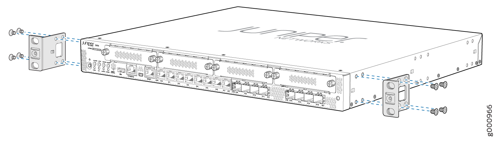 Figure 2: Installing the Rack Mount Brackets (Center Mount Position)
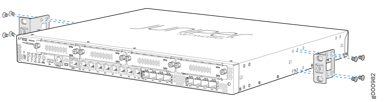
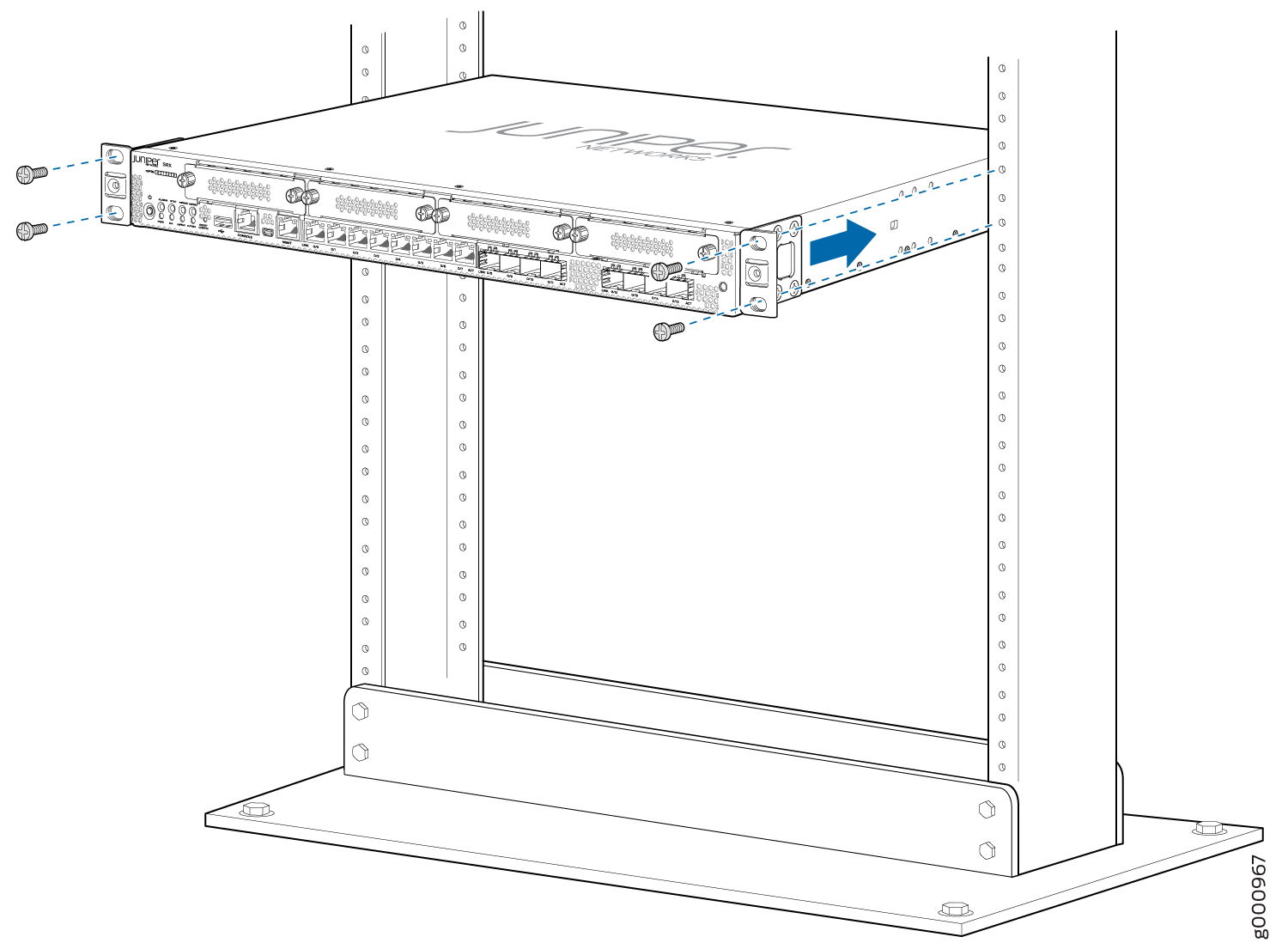
- Install the second screw in each mounting bracket as shown
in Figure 3.Figure 3: Installing the Services Gateway in the Rack (Front Mount Shown, Center Mount Similar)
Installing the SRX345 Firewall on a Wall
You can install the SRX345 firewall on a wall by using the separately orderable wall-mount kit.
Before you install the SRX345:
-
Review the SRX345 Site Guidelines and Requirements.
-
Review the General Safety Guidelines and Warnings.
-
Ensure that you have the following parts and tools available:
-
2 wall-mounting brackets (provided in the wall-mount kit)
-
12 wall-mounting bracket screws (provided in the wall-mount kit)
-
6 mounting screws (8-32 x 1.25 in. or M4 x 30 mm) (not provided)
-
Hollow wall anchors rated to support up to 15.5 lb (7 kg) if you are not screwing the screws directly into wall studs (not provided)
-
Phillips (+) screwdriver, number 2
-
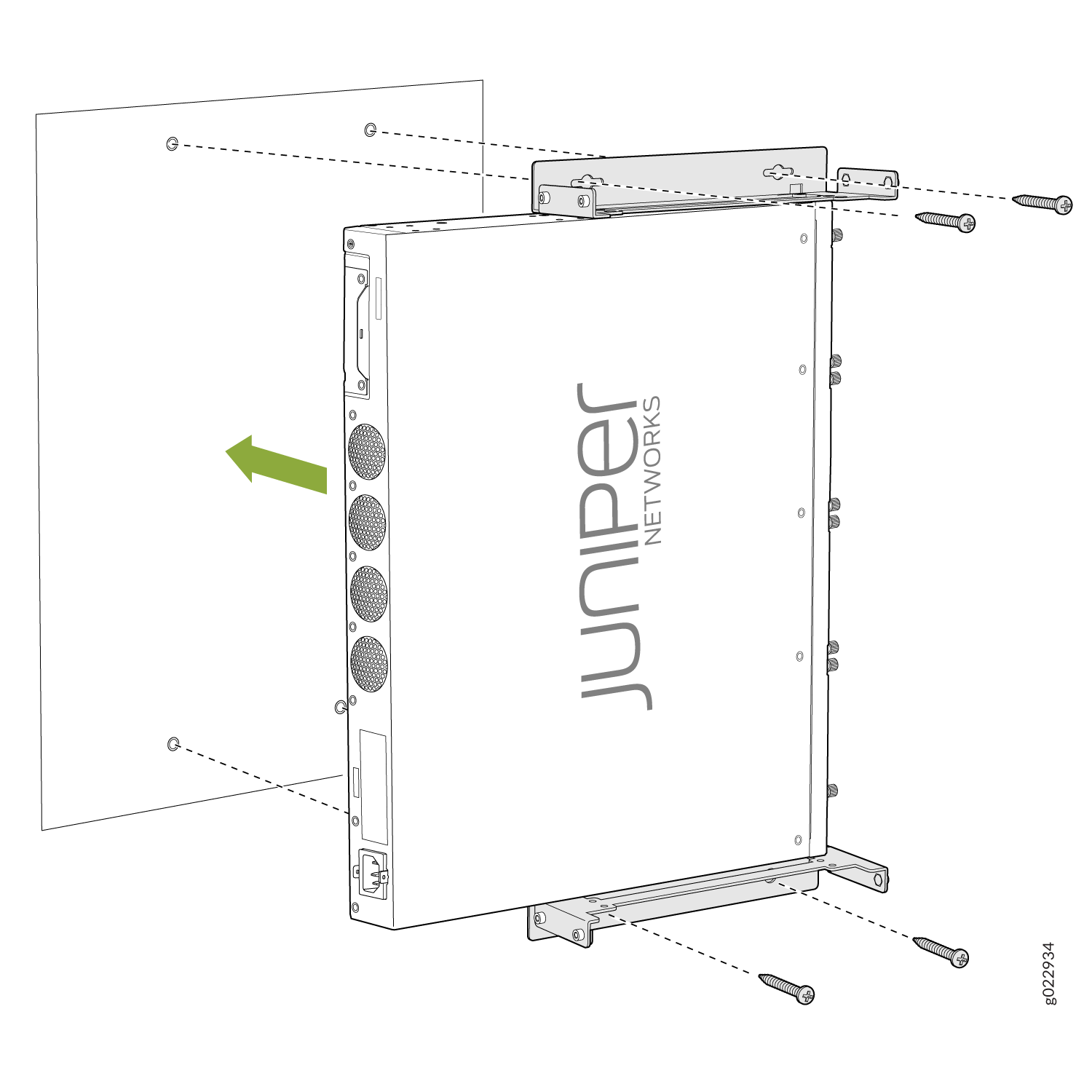
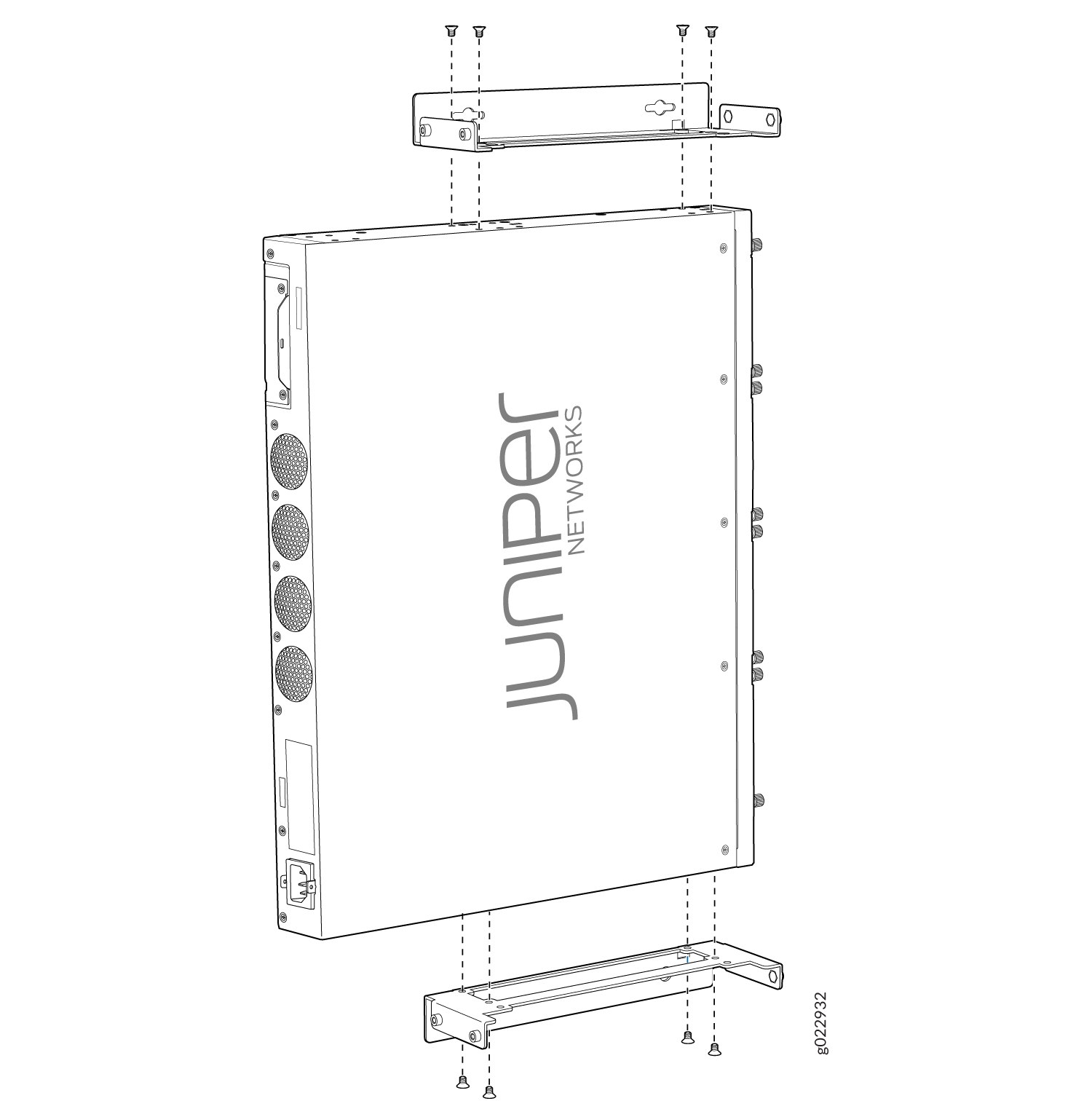
-
Attach the wall-mounting brackets to the side of the chassis using the four
mounting-bracket screws on each side.
Figure 4: Attach Mounting Brackets to the Firewall
-
Install four mounting screws in the wall for the wall-mounting brackets.
- Drill a hole A and install a mounting screw.
- Drill a hole B at a distance of 5.98 in. (15.2 cm) from screw A on a level line to the right and install a mounting screw.
- Drill a hole C at a distance of 18.67 in. (47.43 cm) on a plumb line down from screw A and install a mounting screw.
- Drill a hole D at a distance of 18.67 in. (47.43 cm) on a plumb line down from screw B and install a mounting screw.
Figure 5: Measurements for Installing Mounting Screws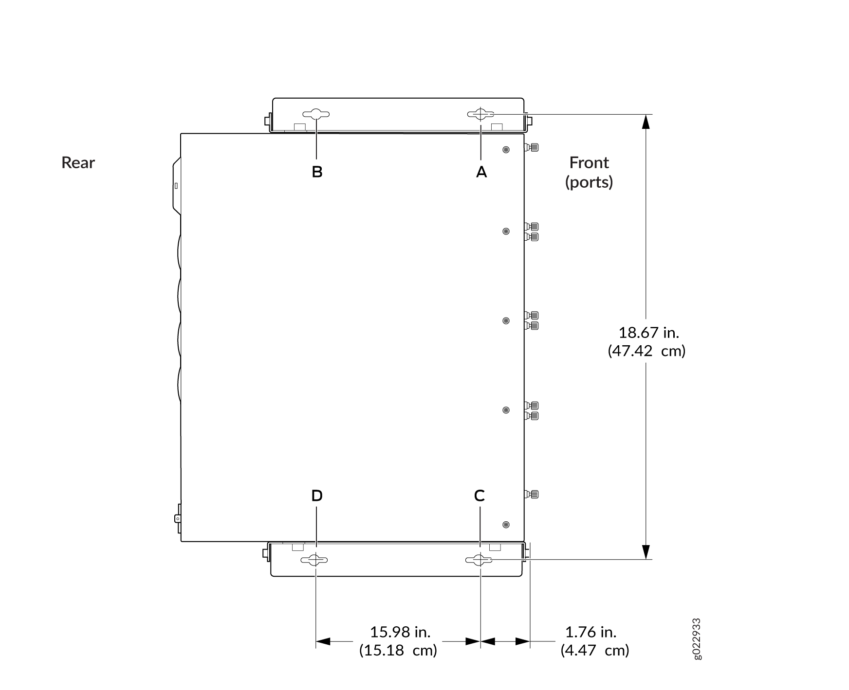 Note:
Note:Tighten the screws only part way in, leaving about 1/4 in. (6 mm) distance between the head of the screw and the wall.
-
Slide the firewall a bit to the left or right so that the mounting screws are pushed
into the holes in the mounting brackets until the firewall rests firmly in place.
Figure 6: Mount the Firewall on a Wall