Connecting the QFX5220 to External Devices
Ground the QFX5220-128C
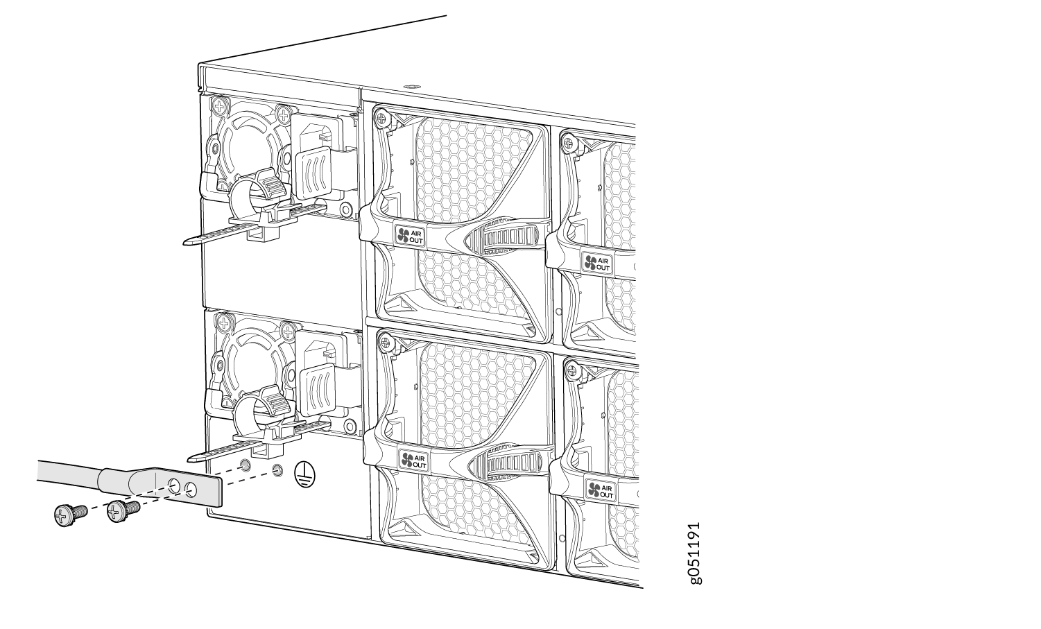
To connect earth ground to a QFX5220-128C:
- Use two 10-32 x 0.25 in. screws with number10 split-lock
washers (not provided) to secure the grounding lug and attached cable
(not provided) to the FRU panel of the chassis. The posts on the grounding
lug should point to the right. See Figure 1.Figure 1: Connecting a Grounding Cable to a QFX5220-128C
Connect Power to the QFX5220-128C
The QFX5220-128C is shipped from the factory with four power supplies. Each power supply is a hot-removable and hot-insertable field-replaceable unit (FRU) when the second power supply is installed and running. You can install a replacement power supply in either of the two slots next to the fan modules without powering off the switch or disrupting the switching function.
To connect AC power to a QFX5220-128C:
- Locate the power cords shipped with the switch; the cords
have plugs appropriate for your geographical location.
For each power supply:
- Ensure the loop on the power cord retainer is open and there is enough space to insert the power cord coupler into the inlet. If the loop is closed, press the small tab on the retainer to loosen the loop.
- Thread the power cord coupler through the power cord retainer loop.
- Insert the power cord coupler firmly into the AC inlet on the power supply faceplate.
- Slide the power cord retainer loop towards the power supply until it is snug against the base of the coupler.
- Press the tab on the loop and draw out the loop to enclose the power cord. See Figure 2.
Figure 2: Attaching the Power Cord Retainer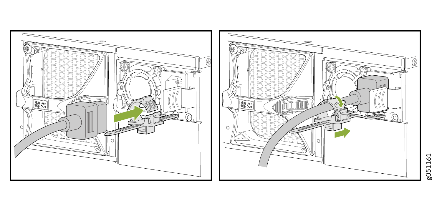 Warning:
Ensure that the power cord does not block access to device components or drape where people can trip on it.
Ground the QFX5220-32CD and Connect Power
To ensure proper operation and to meet safety and electromagnetic interference (EMI) requirements, you must connect the QFX5220 to earth ground before you connect it to power.
For installations that require a separate grounding conductor to the chassis, you must attach a protective earthing terminal bracket on the QFX5220 left front mounting bracket to connect to the earth ground. See Figure 3.
You must install the QFX5220 in a restricted-access location and ensure that the chassis is always properly grounded. The QFX5220 has a two-hole protective grounding terminal provided on the chassis. Under all circumstances, use this grounding connection to ground the chassis. For AC-powered systems, you must also use the grounding wire in the AC power cord along with the two-hole grounding lug connection. This tested system meets or exceeds all applicable EMC regulatory requirements with the two-hole protective grounding terminal.
If an external ground connection is required, ensure that a licensed electrician has attached an appropriate grounding lug to the grounding cable that you supply. Using a grounding cable with an incorrectly attached lug can damage the device.
Mount your switch in the rack or cabinet before attaching the grounding lug to the switch. See Mount a QFX5220-32CD in a Rack or Cabinet by Using the QFX5220-32CD-4PRMK Rack Mount Kit.
Ensure that you have the following parts and tools available:
Grounding cable for your QFX5220 device—The grounding cable must be 14 AWG (2 mm²), minimum 90° C wire, or as permitted by the local code.
Grounding lug for your grounding cable—The grounding lug required is a Panduit LCD10-10A-L or equivalent. The grounding lug attaches to the device chassis through the left-front mounting bracket, providing a protective earthing terminal for the device.
Two 10-32 x 0.25 in. screws with number10 split-lock washers—Two screws are used to secure the grounding lug to the protective earthing terminal. These screws and washers are not provided.
Number 2 screwdriver.
An AC-powered QFX5220 switch chassis gains additional grounding when you plug the power supply in the switch into a grounded AC power outlet by using an AC power cord appropriate for your geographical location.
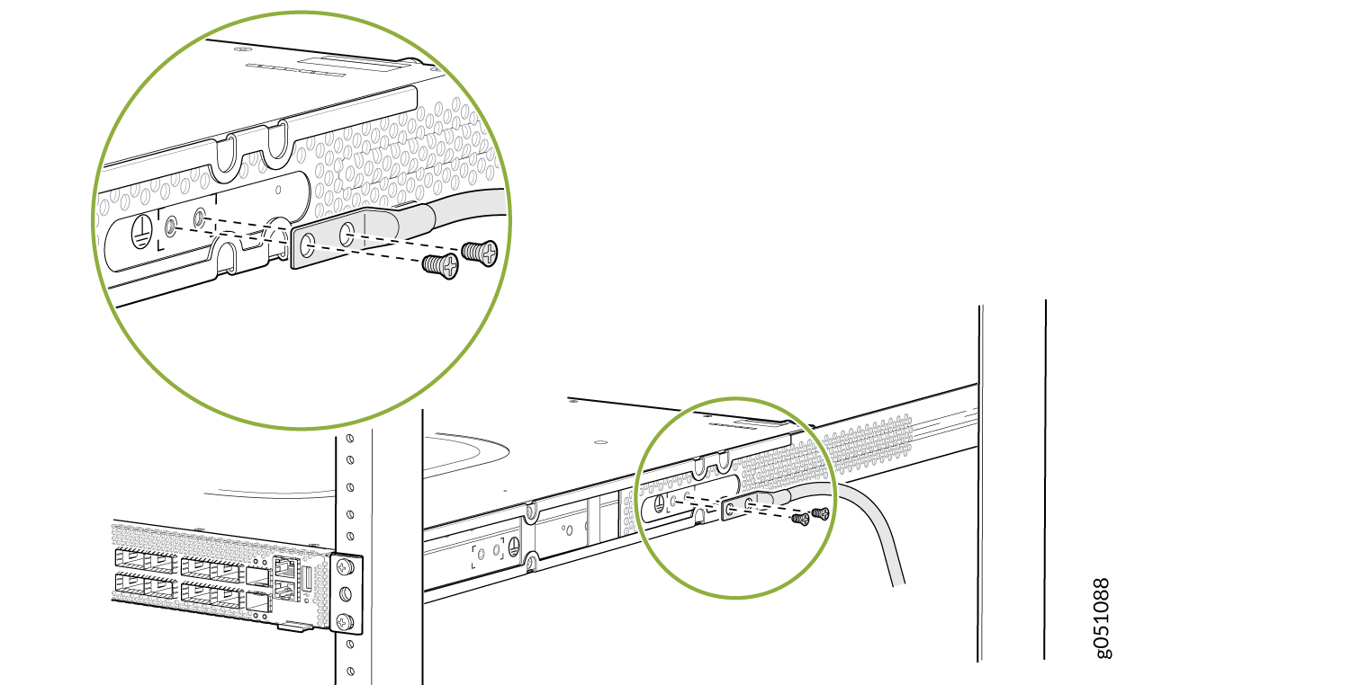
To connect earth ground to a QFX5220-32CD:
- Use the two 10-32 x 0.25 screws with number10 split-lock
washers to secure the grounding lug and attached cable to the chassis.
Attach the lug through the left mounting bracket to the chassis. See Figure 3.Figure 3: Connecting a Grounding Cable to a QFX5220
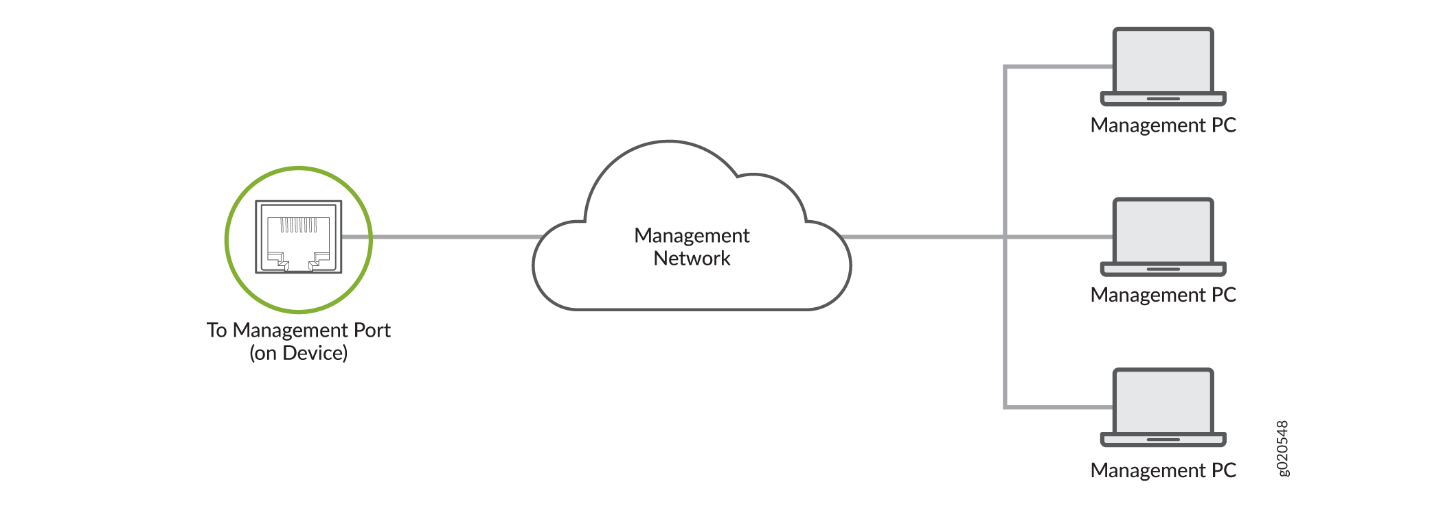
Connect a Device to a Network for Out-of-Band Management
Ensure that you have an Ethernet cable that has an RJ-45 connector at either end.
You can monitor and manage a network device, such as a router or a switch, by using a dedicated management channel. Each device has a management port to which you can connect an Ethernet cable with an RJ-45 connector. Use the management port to connect the device to the management device.
To connect a device to a network for out-of-band management:
- Connect one end of the Ethernet cable to the management port on the device.
- Connect the other end of the Ethernet cable to the management device.
Connect a Device to a Management Console Using an RJ‑45 Connector
Ensure that you have an Ethernet cable that has an RJ-45 connector at either end and an RJ-45-to-DB-9 serial port adapter.
- RJ-45 to DB-9 adapter (JNP-CBL-RJ45-DB9)
- RJ-45 to USB-A adapter (JNP-CBL-RJ45-USBA)
- RJ-45 to USB-C adapter (JNP-CBL-RJ45-USBC)
If you want to use RJ-45 to USB-A or RJ-45 to USB-C adapter, you must have X64 (64-Bit) Virtual COM port (VCP) driver installed on your PC. See https://ftdichip.com/drivers/vcp-drivers/ to download the driver.
If your laptop or desktop PC does not have a DB-9 plug connector pin and you want to connect your laptop or desktop PC directly to the device, use a combination of the RJ-45-to-DB-9 socket adapter and a USB-to-DB-9 plug adapter. You must provide the USB-to-DB-9 plug adapter.
You can configure and manage your network devices using a dedicated management channel. Each device has a console port that you can connect to using an Ethernet cable with an RJ-45 connector. Use the console port to connect the device to the console server or management console. The console port accepts a cable that has an RJ-45 connector.
To connect the device to a management console:
- Connect one end of the Ethernet cable to the console port (labeled CON, CONSOLE, or CON1) on the device.
- Connect the other end of the Ethernet cable to the console server (see Figure 6) or management console (see Figure 7).