ON THIS PAGE
QFX5220 Power System
The power supplies in QFX5220 models are hot-removable and hot-insertable field-replaceable units (FRUs). You can install replacement power supplies without powering off the device or disrupting switching function. The power supplies are installed at the factory and shipped with the chassis. All power supplies for QFX5220 are 1600 W; however, the power supplies for the QFX5220-32CD and the QFX5220-128C are not interchangeable.
Only use the power supply for your model number and airflow. Do not mix power supplies with different airflow or different wattage. The system raises an alarm when a power supply having a different airflow or wattage is inserted into the chassis.
The power supplies for the QFX5220 are located on the FRU panel. See Figure 1 and Figure 2.
A QFX5220 chassis must have a minimum of one PSM available for a row. Acceptable PEM configurations with two PEMs are (0,2), (0,3), (1,2), and (1,3), while configurations with two PEMs that are not supported are (0,1), (2,3).
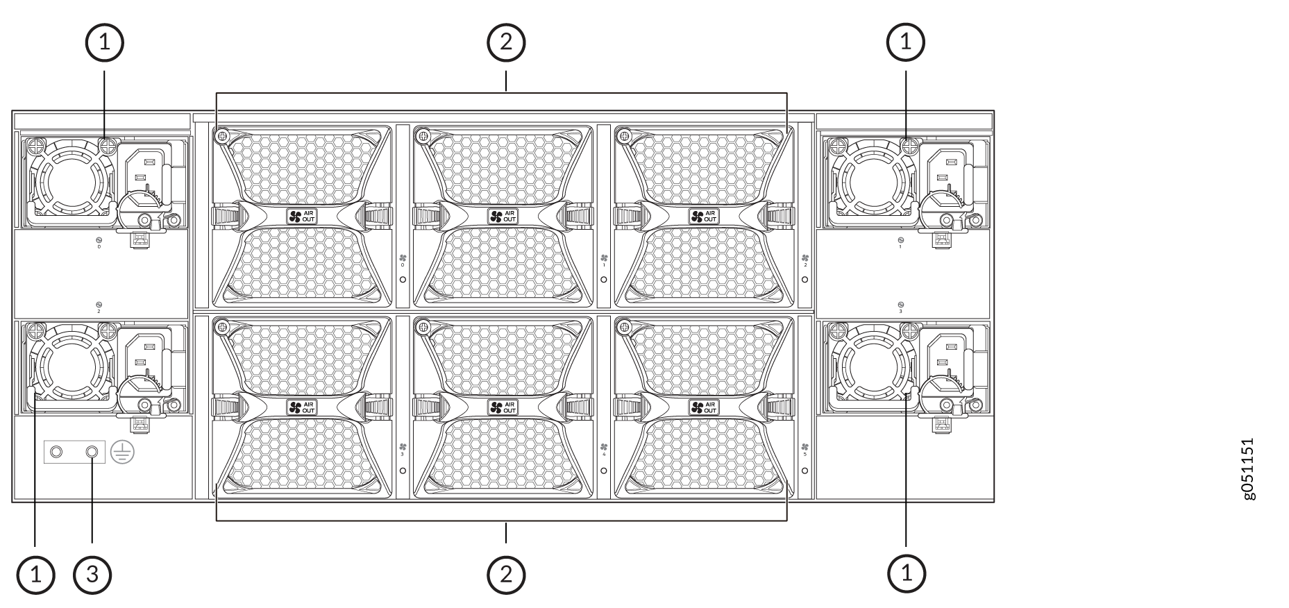
1 — Power supplies | 3 — Chassis protective earthing terminal |
2 — Fans |
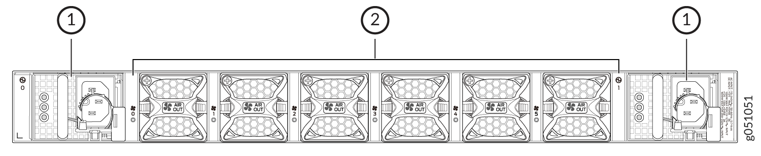
1 — Power supplies | 2 — Fans |
QFX5220 AC Power Supply Modules Description
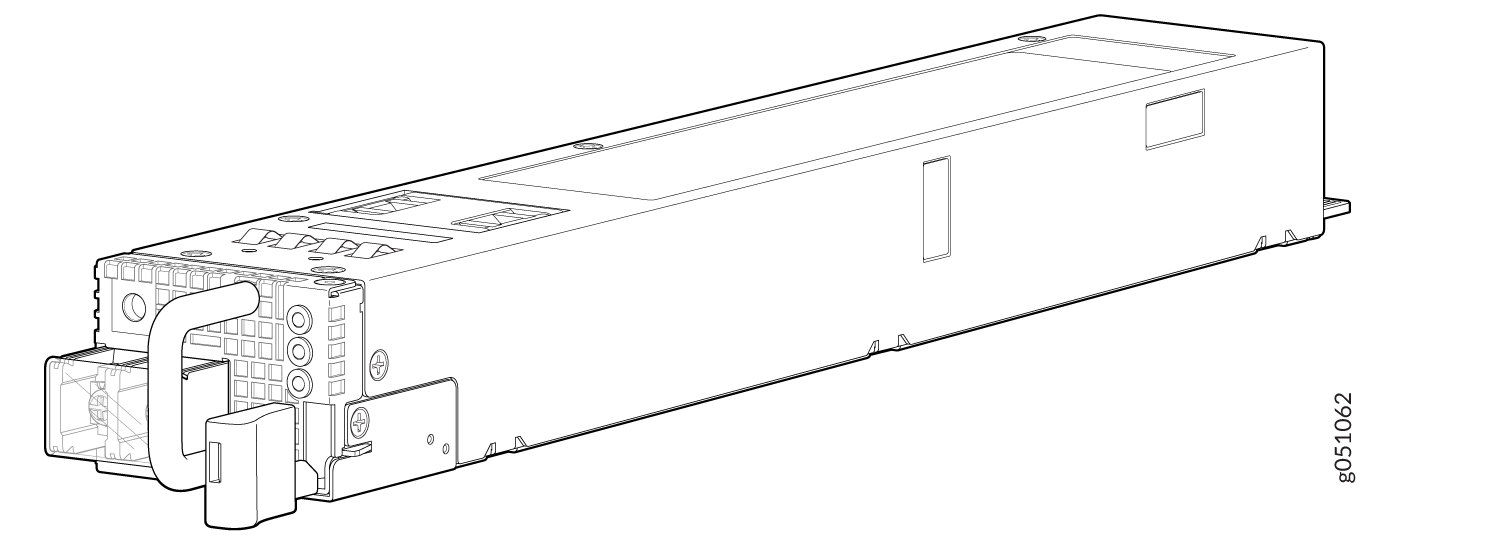
The QFX5220-32CD ships with two power supplies; the QFX5220-128C ships with four power supplies. While each model can operate with the minimum number of power supplies (one for QFX5220-32CD, two for QFX5220-128C), maximum power supplies are required to have redundancy. See Figure 3 and Figure 4 for examples of these power supply modules.
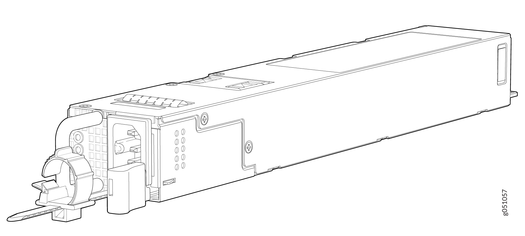
1 — Power connector | 3 — Ejection lever |
2 — Power LED | 4 — Handle |
An AC power supply for the QFX5220 is 1600 W. However, the power supplies for the QFX5220-32CD and the QFX5220-128C are not interchangeable. Be sure to use the correct power supply for your chassis product variant (see Table 1 ).
The power supply provides FRU-to-port or port-to-FRU airflow depending on the model and variant you purchase. The power supplies have color-coded indicators to indicate the airflow direction.
|
Model |
Product Number |
Airflow Direction |
Color Indicator |
|---|---|---|---|
|
QFX5220-32CD |
JPSU-1600W-1UACAFI |
Airflow In (FRU-to port) |
Juniper azure blue handle |
|
JPSU-1600W-1UACAFO |
Airflow Out (port-to-FRU) |
Juniper gold handle |
|
|
QFX5220-128C |
JPSU-1600W-AC-AFO |
Airflow Out (port-to-FRU) |
Juniper gold handle |
Verify that the airflow direction on the power supply handle matches the direction of airflow in the chassis. Ensure that each power supply you install in the chassis has the same airflow direction. If you install power supplies with two different airflow directions, Junos OS raises an alarm. If you need to convert the airflow pattern on a chassis, you must change out all the fans and power supplies at one time to use the new direction.
To avoid electrical injury, carefully follow instructions in Connecting the QFX5220 to Power.
QFX5220 AC Power Specifications
Table 2 describes the AC power specifications for a QFX5220.
|
Item |
Specification |
|
|---|---|---|
|
AC input voltage |
QFX5220-32CD QFX5220-128C |
Operating range: 100 - 240 VAC Operating range: 100 / 240 VAC |
|
AC input line frequency |
50–60 Hz |
|
|
AC input current rating |
QFX5220-32CD |
12.7 A at 100-127 VAC 9.4 A at 200-240 VAC |
|
QFX5220-128C |
19.36 A at 100-127 VAC 10.95 A at 200-240 VAC |
|
|
Typical power consumption |
QFX5220-32CD |
220-240 V: 310-W |
|
QFX5220-128C |
220-240 V: 942-W |
|
|
Maximum power consumption |
QFX5220-32CD |
220-240 V: 834-W |
|
QFX5220-128C |
220-240 V: 1506-W |
|
Typical power consumption is measured at 25°C ambient temperature with DACs, and at 50% load with IMIX traffic, excluding transceivers for QFX5220-32CD. Power consumption is subject to operating conditions and unit-to-unit variations. Maximum power consumption is measured at 40°C ambient temperature with SR optics, and at 100% load with IMIX traffic.
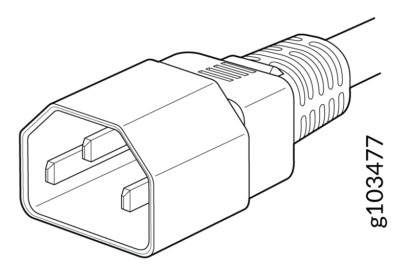
AC Power Cord Specifications
QFX5220 switches are now shipped with standardized PDU cables by default, designed for modern data centers that use IEC connector types. For customers operating in older data centers, earlier country‑specific power cables remain available.
| Country | Specifications | Shipped Power Cable | Graphic |
|---|---|---|---|
| India |
Power Cord, AC, India, C13, 10A, 250V, 2m, Straight, C14 to C15 |
CBL-C15-C14-IN-2M |
 |
| Taiwan | Power Cord, AC, Taiwan, C14, 10A, 250V, 2m, Straight, C14 to C15 |
CBL-C15-C14-TW-2M |
|
| United States, Japan | Power Cord, AC, US, Japan, C14, 10A, 250V, 2m, Straight, C14 to C15 | CBL-C15-C14-TW-2MCBL-C15-C14-US-2M | |
| Europe, Israel, South Africa | Power Cord, AC, Europe,Israel,South Africa,10A, 250V, 2m, Straight, C14 to C15 | CBL-C15-C14-EU-2M | |
| Brazil, China, South Korea | Power Cord, AC, Brazil,China,South Korea C14,10A, 250V, 2m, Straight, C14 to C15 | CBL-C15-C14-CN-2M | |
| Country | Specifications | Shipped Power Cable | Graphic |
|---|---|---|---|
| All countries (International) |
Power Cord, AC, International(except India) C13, 10A, 250V, 2m, Straight, C13 to C14 |
CBL-C13-C14-INT-2M |
|
| India | Power Cord, AC, India, C13, 10A, 250V, 2m, Straight, C13 to C14 |
CBL-C13-C14-IN-2M |
|
You can also order country-specific AC power cords separately, if required. The plug end of the power cord fits into the power source outlet that is standard for your geographical location.
In North America, AC power cords must not exceed 14.75 feet (approximately 4.5 meters) in length, to comply with National Electrical Code (NEC) Sections 400-8 (NFPA 75, 5-2.2) and 210-52, and Canadian Electrical Code (CEC) Section 4-010(3). The cords that can be ordered for the QFX Series switches are in compliance.
Table 5 lists the country-specific power cord specifications for QFX5220-32CD.
|
Country/Region |
Electrical Specifications |
Plug Standards |
Juniper Model Number |
Spare Juniper Model Number |
Graphic |
|---|---|---|---|---|---|
|
Argentina |
250 VAC, 10 A, 50 Hz |
IRAM 2073 Type RA/3 |
– |
CBL-PWR-C15M-HITEMP-AR |
|
|
Australia |
250 VAC, 10 A, 50 Hz |
AS/NZS 3112-2000 Type SAA/3 |
CG_CBL-C15-02-AU |
CBL-PWR-C15M-HITEMP-AU |
|
|
Brazil |
250 VAC, 10 A, 50 Hz |
NBR 14136 Type BR/3 |
– |
CBL-PWR-C15M-HITEMP-BR |
|
|
China |
250 VAC, 10 A, 50 Hz |
GB 2099/GB 1002 Type PRC/3 |
CG_CBL-C15-02-CH |
CBL-PWR-C15M-HITEMP-CH |
|
|
Europe (except Italy, Switzerland, and United Kingdom) |
250 VAC, 10 A, 50 Hz |
CEE (7) VII Type VIIG |
CG_CBL-C15-02-EU |
CBL-PWR-C15M-HITEMP-EU |
|
|
Europe (except Italy, Switzerland, and United Kingdom) |
250 VAC, 10 A, 50 Hz |
Europe patch cord - Straight,C15 Plug (EN 60320) to C14 Connector (EN 60320)- |
CBL-PWR-C15-C14-EU |
||
|
Italy |
250 VAC, 10 A, 50 Hz |
CEI 23-16 Type I/3G |
CG_CBL-C15-02-IT-CH |
CBL-PWR-C15M-HITEMP-IT |
|
|
Japan |
125 VAC, 15 A, 50 Hz |
JIS 8303 Type 498GJ |
CG_CBL-C15-02-JP |
CBL-PWR-C15M-HITEMP-JP |
|
|
North America |
125 VAC, 15 A, 50 Hz |
NEMA 5-15 Type 498G |
CG_CBL-C15-02-US |
CBL-PWR-C15M-HITEMP-US |
|
|
North America |
125 VAC, 15 A, 50 Hz |
US Patch cord - Straight,C15 Plug (EN 60320) to C14 Connector (EN 60320) |
CBL-PWR-C15-C14-US |
CBL-PWR-C15M-HITEMP-US |
|
|
South Africa and India |
250 VAC, 10 A, 50 Hz |
SABS 164/1:1992 Type ZA/3 |
– |
CBL-PWR-C15M-HITEMP-SA |
|
|
South Korea and some parts of Europe |
250 VAC, 10 A, 50 Hz |
CEE(7) VII Type VIIG |
– |
CBL-PWR-C15M-HITEMP-KR |
|
|
Switzerland |
250 VAC, 10 A, 50 Hz |
SEV 1011/6534-2 Type 12G |
CG_CBL-C15-02-SZ |
CBL-PWR-C15M-HITEMP-SZ |
|
|
United Kingdom |
250 VAC, 10 A, 50 Hz |
BS 1363/A Type BS89/13 |
CG_CBL-C15-02-UK |
CBL-PWR-C15M-HITEMP-UK |
|
Table 6 lists the country-specific power cord specifications for QFX5220-32CD.
|
Country/Region |
Electrical Specifications |
Plug Standards |
Shipped Juniper Model Number |
Spare Juniper Model Number |
Graphic |
|---|---|---|---|---|---|
|
Australia |
250 VAC, 10 A, 50 Hz |
AS/NZ 3109-1996 |
CG_CBL-C13-06-AU |
CBL-EX-PWR-C13-AU |
|
|
China |
250 VAC, 10 A, 50 Hz |
GB 1002-1996 |
CG_CBL-C13-06-CH |
CBL-EX-PWR-C13-CH |
|
|
Europe (except Italy, Switzerland, and United Kingdom) |
250 VAC, 10 A, 50 Hz |
CEE (7) VII |
CG_CBL-C13-06-EU |
CBL-EX-PWR-C13-EU |
|
|
Italy |
250 VAC, 10 A, 50 Hz |
CEI 23-16/VII |
CG_CBL-C13-06-IT |
CBL-EX-PWR-C13-IT |
|
|
Japan |
125 VAC, 12 A, 50 Hz or 60 Hz |
JIS C8303 |
CG_CBL-C13-06-JP |
CBL-EX-PWR-C13-JP |
|
|
North America |
125 VAC, 13 A, 60 Hz |
EN 60320 C13 NEMA 5-15P |
CG_CBL-C13-06-US |
CBL-EX-PWR-C13-US |
|
|
India |
250 VAC, 10 A, 50 Hz |
IS 1293 Type IND/3 |
CG_CBL-C13-06-IN |
CBL-EX-PWR-C13-IN |
|
|
South Korea |
250 VAC, 10 A, 60 Hz |
KS C 8305 60227-5 IEC 60227-7 IEC |
CG_CBL-C13-06-KR |
CBL-EX-PWR-C13-KR |
|
|
Switzerland |
250 VAC, 10 A, 50 Hz |
SEV 1011 SEV 1991; EN 60320 C13 |
CG_CBL-C13-06-SZ |
CBL-EX-PWR-C13-SZ |
|
|
United Kingdom |
250 VAC, 10 A, 50 Hz |
BS 1363/A |
CG_CBL-C13-06-UK |
CBL-EX-PWR-C13-UK |
|
See Also
QFX5220 AC Power Supply LEDs
The QFX5220-128C uses a single bi-colored LED to indicate power status. Figure 5 shows the location of the LED on the JPSU-1600W-AC-AFO and Table 11 explains the LED behavior on QFX5220-128C power supplies.
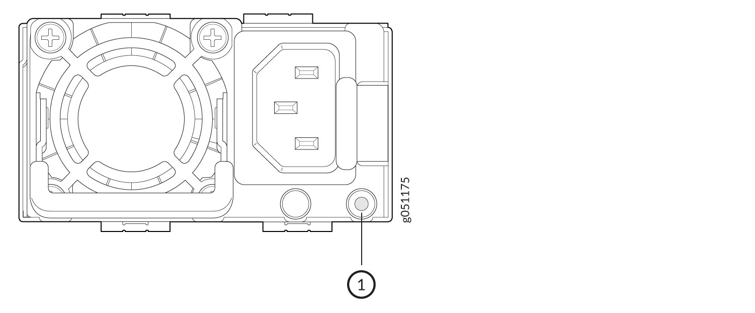
1 — Status LED |
The QFX5220-32CD uses three LEDs to indicate power status. Figure 6 shows the location of the LEDs on the JPSU-1600W-1UAC power supply.
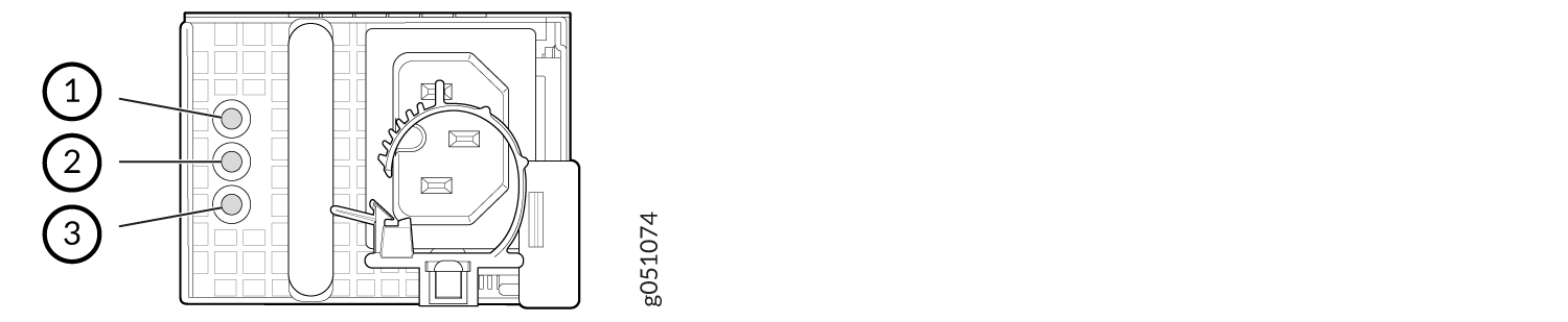
1 — AC input okay | 3 — Fault condition |
2 — DC output okay |
Table 7 describes the LED behavior on the QFX5220-32CD AC power supplies.
|
LED |
Color |
State |
Description |
|---|---|---|---|
|
AC input okay |
Unlit |
Off |
The power supply is disconnected from power, or power is not coming into the power supply. |
|
Green |
On steadily |
Power is coming into the power supply. |
|
|
DC output okay |
Unlit |
Off |
The power supply is disconnected from power, or the power supply is not sending out power correctly. |
|
Green |
On steadily |
The power supply is sending out power correctly. |
|
|
Fault |
Amber |
On steadily |
An error has been detected in the power supply. Replace the power supply as soon as possible. To maintain proper airflow through the chassis, leave the power supply installed in the chassis until you are ready to replace it. |
|
Blinking |
The power supply is an invalid model. |
If the input and output LEDs are unlit, either the AC power cord is not installed properly or the power supply fuse has failed. If the input LED is lit and the output LED is unlit, the AC power supply is installed properly, but the power supply has an internal failure.
QFX5220 DC Power Supply Description
The DC power supplies in the QFX5220 (see Figure 7 and Figure 8) are hot-removable and hot-insertable field-replaceable units (FRUs) that install without powering off the device or disrupting the switching function. The factory installed power supplies in both models are 1600-W, but are not interchangeable. The QFX5220-128C switch has four power supplies and the QFX5220-32CD is shipped with two power supplies. Each power supply provides 1600 W of power to the chassis.
Both power supplies have double the amount of power supplies needed to power all of the components in the switch, which is known as 2n redundancy. When the switch has all of the power supplies installed, the switch has full power redundancy. If a power supply fails or is removed, a second power supply balances the electrical load without interruption. For more on redundancy features, see QFX5220 Component Redundancy. Each power supply provides 12-VDC output with a standby voltage of 12 VDC.
1 — Power LED | 3 — Handle |
2 — Ejector lever |
Verify that the airflow direction on the power supply handle matches the direction of airflow in the chassis. Ensure that each power supply you install in the chassis has the same airflow direction. If you install power supplies with two different airflow directions, Junos Evolved raises an alarm. If you need to convert the airflow pattern on a chassis, you must change out all the fans and power supplies at one time to use the new direction.
Table 8 shows the characteristics of the power supply and the direction of the airflow.
|
Model |
Wattage |
Product Number |
Direction of Airflow |
Color of Power Supply Handle |
|---|---|---|---|---|
|
QFX5220-128C |
1600-W |
JPSU-1600W-DC-AFO |
Airflow Out (port-to-FRU) |
Juniper gold |
|
QFX5220-32CD |
1600-W |
JPSU-1600W-1UDCAFI |
Airflow In (FRU-to port) |
Juniper azure blue handle |
|
1600-W |
JPSU-1600W-1UDCAFO |
Airflow Out (port-to-FRU) |
Juniper gold handle |
We recommend that the 48 VDC facility DC source be equipped with a circuit breaker rated at 40 A (–48 VDC) minimum, or as required by local code.
To avoid electrical injury, carefully follow instructions in Maintaining the QFX5220 Power System .
QFX5220 DC Power Specifications
Table 9 describes the DC power specifications for the DC version of a QFX5220 switch.
|
Item |
Model |
Specifications |
|---|---|---|
|
DC input voltage |
|
|
|
DC input current rating |
QFX5220-128C QFX5220-32CD |
40 A maximum |
|
Typical power consumption |
QFX5220-32CD |
328-W |
|
QFX5220-128C |
955-W |
|
|
Maximum power consumption |
QFX5220-32CD |
860-W |
|
QFX5220-128C |
1530-W |
Typical power consumption is measured at 25°C ambient temperature with DACs, and at 50% load with IMIX traffic, excluding transceivers for QFX5220-32CD. Power consumption is subject to operating conditions and unit-to-unit variations. Maximum power consumption is measured at 40°C ambient temperature with SR optics, and at 100% load with IMIX traffic.
We recommend that the 48 VDC facility DC source be equipped with a circuit breaker rated at 40 A (–48 VDC) minimum, or as required by local code.
QFX5220-128C DC Power Cable Specification
QFX5220-128C DC power supplies require a D-Sub 3W3- type connector. The three pins on the connector provide –48 VDC input (–), return (+), and ground connections to the power supply.
The optional right-angle DC power cables, CBL-JNP-PWR-DSUB2 and CBL-JNP-PWR-DSUB3, do not include a ground connection wire. Regardless which DC power cable you use, you must connect the QFX5220 to earth ground before you connect it to power, using the procedure described in Ground the QFX5220-128C.
DC power cables, each 4 m (approximately 13.1 ft) long, are supplied with the QFX5220-128C. The provided cables include the three-pin connector on one end and three insulated wires at the opposite end, for connection to the site’s DC power distribution system.
Table 10 lists the specifications for the QFX5220-128C DC power cables.
|
Juniper Model Number |
Wire Function |
Insulation Color |
Wire Size |
|---|---|---|---|
|
CBL-JNP-PWR-DSUB (straight cable) |
–48 VDC input (–) |
Blue |
8 AWG (8.4 mm²), 90° C |
|
Return (+) |
Black |
8 AWG (8.4 mm²), 90° C |
|
|
Ground |
Green and yellow |
8 AWG (8.4 mm²), 90° C |
|
| CBL-JNP-PWR-DSUB2 (right-angle cable) | –48 VDC input (–) | Blue | 8 AWG (8.4 mm²), 90° C |
| Return (+) | Black | 8 AWG (8.4 mm²), 90° C | |
|
CBL-JNP-PWR-DSUB3 (FT4 vertical-flame rated, right-angle cable) |
–48 VDC input (–) | Gray | 8 AWG (8.4 mm²), 90° |
| Return (+) | Gray | 8 AWG (8.4 mm²), 90° C |
For field-wiring connections, use copper conductors only.
Power cables must not block access to QFX5220 components or drape where people could trip on them.
You must ensure that power connections maintain the proper polarity. The power source cables might be labeled (+) and (–) to indicate their polarity. There is no standard color coding for DC power cables. The color coding used by the external DC power source at your site might be different from the color coding for the leads on the DC power cable provided with the chassis.
QFX5220-128C DC Power Supply LED
Figure 9 shows the location of the status LED on the QFX5220-128C DC power supply.
1 — Status LED |
Table 11 describes the status LED behavior on QFX5220-128C power supplies.
|
LED Color |
State |
Description |
|---|---|---|
|
Unlit |
Off |
The power supply is disconnected from power, or power is not coming into the power supply. |
|
Green |
On steadily |
The power supply is operating correctly. |
|
Amber |
On steadily |
A power supply fault or error has occurred in the power supply. Replace the power supply as soon as possible. To maintain proper airflow through the chassis, leave the power supply installed in the chassis until you are ready to replace it. |
You can get additional information about the status of the power
modules using the show chassis environment pem. For example:
user@device> show chassis environment pem

PSM1 status:
  State                      Online
  Temperature                25 degrees C / 77 degrees F
  Fans                       OK
  DC Output                  Failed
PSM3 status:
  State                      Online
  Temperature                25 degrees C / 77 degrees F
  Fans                       OK
  DC Output                  Failed
QFX5220-32CD-D DC Power Supply LED
Figure 10 shows the location of the power supply status LEDs.
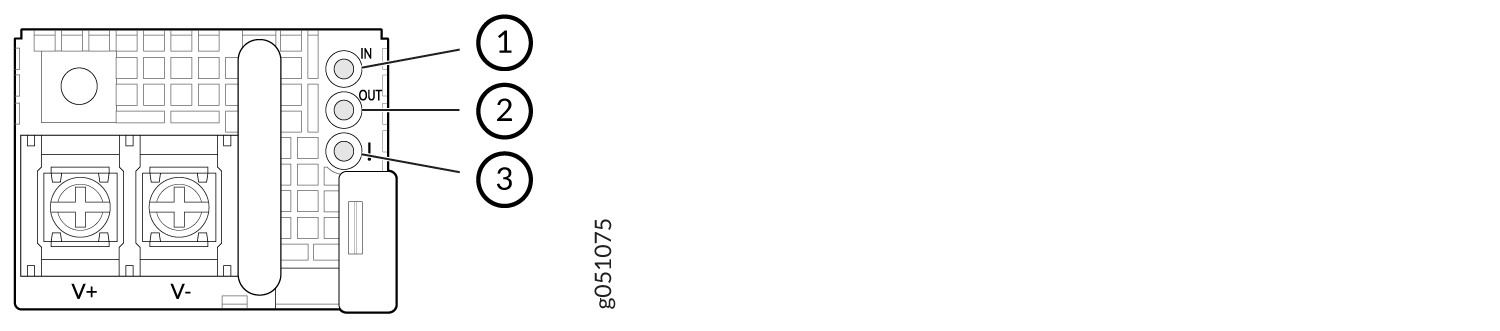
1 — Input OK | 3 — Fault |
2 — Output OK |
Table 12 describes the status LED behavior on QFX5220-32CD power supplies.
|
Status |
LED Color |
Description |
|---|---|---|
|
Input OK |
Off |
The power supply is disconnected from power, or power is not coming into the power supply. |
|
Green, on steadily |
Input voltage is present and is within range. |
|
|
Output OK |
Off |
The power supply is running at the power limit or is over current. |
|
Green, on steadily |
The power supply is operating correctly. |
|
|
Fault |
Amber, on steadily |
A power supply fault or error has occurred in the power supply. Replace the power supply as soon as possible. To maintain proper airflow through the chassis, leave the power supply installed in the chassis until you are ready to replace it. |
|
Amber, blinking |
The power supply is not valid. Check the model number. |