Help us improve your experience.

Let us know what you think.

Do you have time for a two-minute survey?


Maintaining the QFX5220 Power System

A QFX5220 power supply module (PSM) is a hot-removable and hot-insertable field-replaceable unit (FRU). You can install replacement power supplies without powering off the switch or disrupting the switching function.

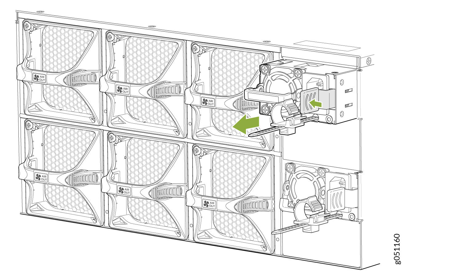
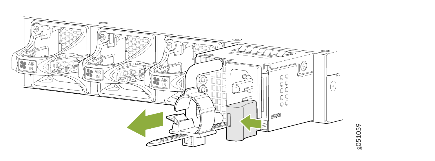
How to Remove a Power Supply from a QFX5220

Before you remove a power supply from a QFX5220, ensure that you have taken the necessary precautions to prevent electrostatic discharge (ESD) damage (see Prevention of Electrostatic Discharge Damage).

Figure 1: Removing an AC Power Supply from QFX5220-128CRemoving an AC Power Supply from QFX5220-128C
Figure 2: Removing an AC Power Supply from QFX5220-32CDRemoving an AC Power Supply from QFX5220-32CD

Ensure that you have the following parts and tools available to remove a power supply from a QFX5220:

  • ESD grounding strap

  • Antistatic bag or an antistatic mat

The QFX5220-32CD is shipped from the factory with two power supplies, while the QFX5220-128C is shipped with four power supplies. See Figure 1 and Figure 2.

To remove a power supply from a QFX5220 (see Figure 3):

  1. Place the antistatic bag or the antistatic mat on a flat, stable surface.
  2. Attach the ESD grounding strap to your bare wrist, and connect the strap to the ESD point on the chassis.
    Note:

    If only one power supply is installed in your QFX5220, you need to power off the switch before removing the power supply. See Powering Off a QFX5220.

  3. Disconnect power to the switch:
    • AC power supply—If the AC power source outlet has a power switch, set it to the OFF (O) position. If the AC power source outlet does not have a power switch, gently pull out the plug end of the power cord connected to the power source outlet.

    • DC power supply—Switch the circuit breaker on the panel board that services the DC circuit to the OFF position.

  4. Remove the power source cable from the power supply faceplate:
    • AC power supply—Remove the power cord from the power supply faceplate by detaching the power cord retainer and gently pulling out the socket end of the power cord connected to the power supply faceplate.

    • DC power supply

      • QFX5220-128C

        1. Use a Phillips screwdriver to detach the grounding cable.

        2. Loosen the thumb screws for the power cord.

        3. Gently pull out the socket end of the power plug connected to the power supply faceplate.

      • QFX5220-32CD.

      1. Remove the screws that secure the ring lugs to the terminals using the screwdriver.

      2. Replace the screws to each terminal and tighten the screws using the screwdriver.

  5. Slide the locking lever toward the handle until it stops.
  6. Grasp the power supply handle and pull firmly to slide the power supply halfway out of the chassis. See Figure 3 and Figure 4.
    Figure 3: Removing a DC Power Supply from a QFX5220-32CDRemoving a DC Power Supply from a QFX5220-32CD
    Figure 4: Removing a DC Power Supply from a QFX5220-128CRemoving a DC Power Supply from a QFX5220-128C
  7. Place one hand under the power supply to support it and slide it completely out of the chassis. Take care not to touch power supply components, pins, leads, or solder connections.
  8. Place the power supply in the antistatic bag or on the antistatic mat placed on a flat, stable surface.
  9. Replace with another power supply module.

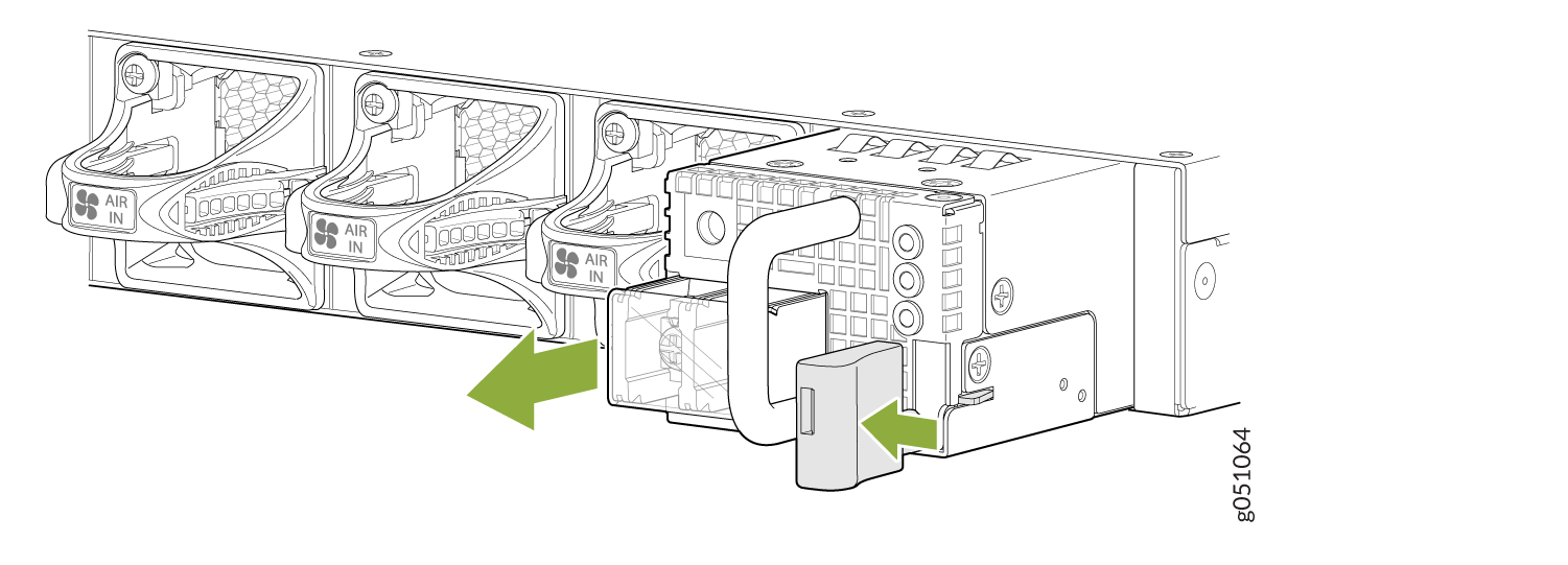
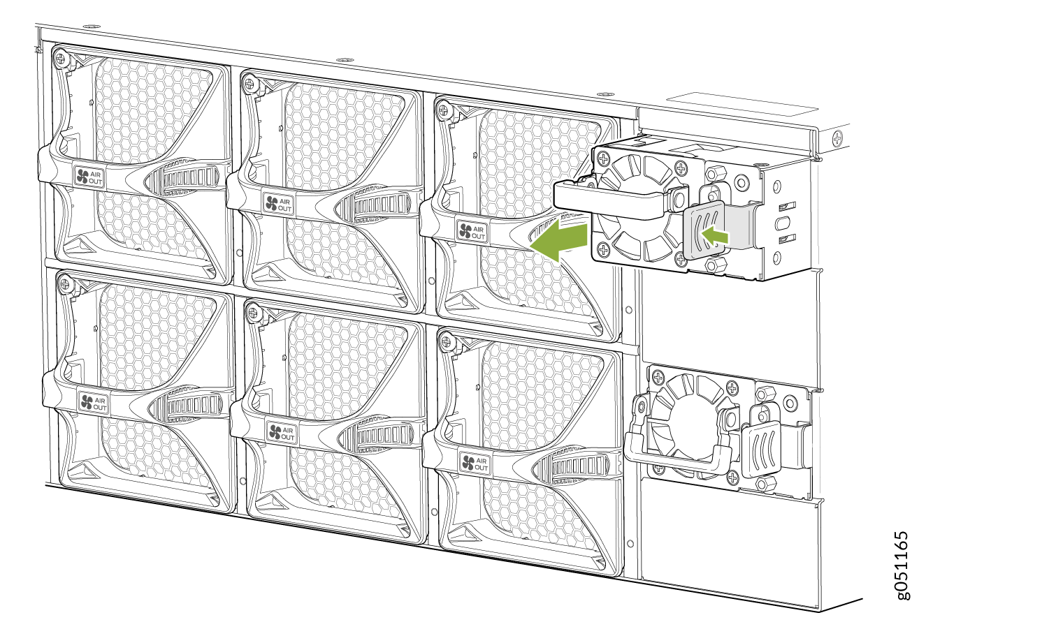
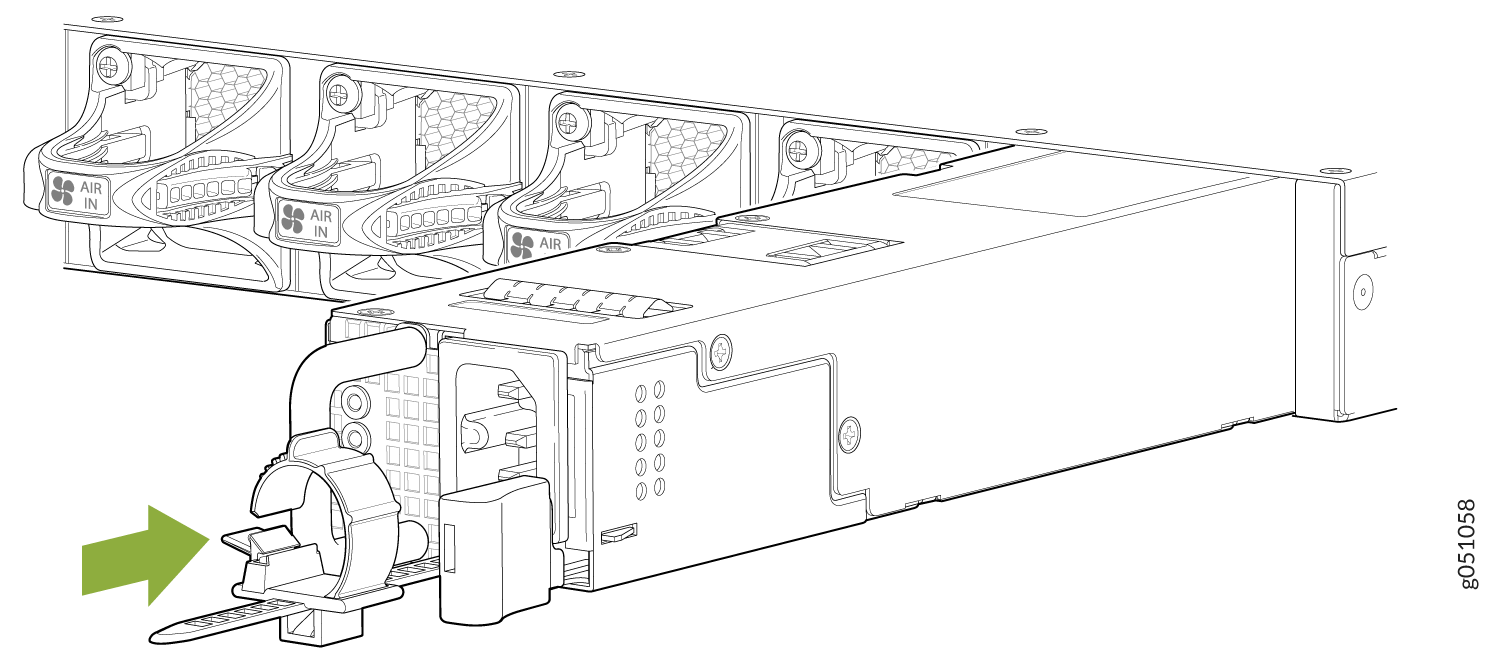
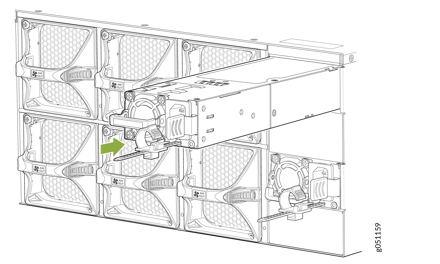
How to Install an AC Power Supply in a QFX5220

  • Before you install a power supply in a QFX5220, ensure that you have taken the necessary precautions to prevent electrostatic discharge (ESD) damage (see Prevention of Electrostatic Discharge Damage).

  • Ensure that the airflow direction of the power supply is the same as the chassis. Labels on the power supply handle indicate the direction of airflow. SeeQFX5220 Cooling System for more information.

To install a power supply in a QFX5220 (see Figure 5):

  1. Attach the ESD grounding strap to your bare wrist, and connect the strap to the ESD point on the chassis.
  2. Take care not to touch power supply components, pins, leads, or solder connections as you remove the power supply from its bag.
    CAUTION:

    Verify that the direction of the arrow on the power supply handle matches the direction of airflow in the chassis. Ensure that each power supply you install in the chassis has the same airflow direction. If you install power supplies with two different airflow directions, Junos OS raises an alarm, and the status (ALM) LED blinks amber.

  3. If the power supply has a protective plastic wrap, peel and remove the plastic wrap from all four sides of the power supply.
  4. Using both hands, place the power supply in the power supply slot on the FRU panel of the switch and slide it in until it is fully seated and the locking lever slides into place. See Figure 5 and Figure 6.
Figure 5: Installing a QFX5220-32CD AC Power SupplyInstalling a QFX5220-32CD AC Power Supply
Figure 6: Installing a QFX5220-128C AC Power SupplyInstalling a QFX5220-128C AC Power Supply
Note:

Each power supply must be connected to a dedicated power source outlet.

Note:

If you have a Juniper Care service contract, register any addition, change, or upgrade of hardware components at https://www.juniper.net/customers/support/tools/updateinstallbase/ . Failure to do so can result in significant delays if you need replacement parts. This note does not apply if you replace existing components with the same type of component.