Connecting the QFX5210
Connecting the QFX5210 to Ground
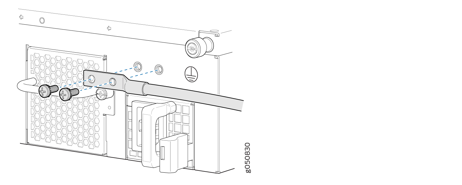
You must install the QFX5210 in a restricted-access location and ensure that the chassis is always properly grounded. The QFX5210 has a two-hole protective grounding terminal provided on the chassis. See Figure 1. Under all circumstances, use this grounding connection to ground the chassis. For AC-powered systems, you must also use the grounding wire in the AC power cord along with the two-hole grounding lug connection. This tested system meets or exceeds all applicable EMC regulatory requirements with the two-hole protective grounding terminal.
If an external ground connection is required, ensure that a licensed electrician has attached an appropriate grounding lug to the grounding cable that you supply. Using a grounding cable with an incorrectly attached lug can damage the switch (for example, by causing a short circuit).
Mount your switch in the rack or cabinet before attaching the grounding lug to the switch. See Unpacking and Mounting the QFX5210.
Ensure that you have the following parts and tools available:
Grounding cable for your QFX5210—The grounding cable must be 10 AWG (5 mm²), minimum 90° C wire, or as permitted by the local code.
Grounding lug for your grounding cable—The grounding lug required is a Panduit LCD10-10A-L or equivalent (not provided).
Two #10-32 UNF screws and washers (not provided).
Screwdriver appropriate for the #10-32 UNF screws (not provided).
An AC-powered QFX5210 switch chassis gains additional grounding when you plug the power supply in the switch into a grounded AC power outlet by using an AC power cord appropriate for your geographical location. See AC Power Cords.
To connect earth ground to a QFX5210:
- Secure the protective earthing terminal bracket to the
FRU panel of the QFX5210 chassis with two #10-32 UNF screws. The posts
on the protective earthing terminal bracket should point to the left.
See Figure 1 .Figure 1: Connecting a Grounding Cable to a QFX5210-64C
See Also
Connect a Device to a Network for Out-of-Band Management
Ensure that you have an Ethernet cable that has an RJ-45 connector at either end.
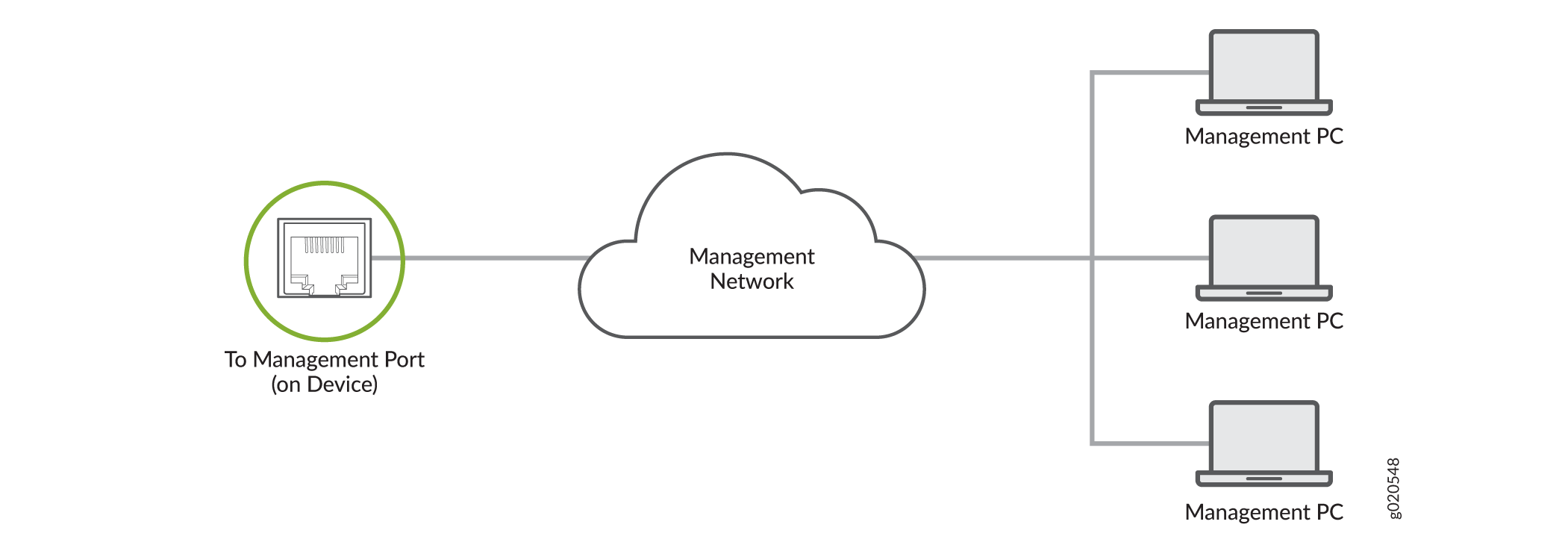
You can monitor and manage a network device, such as a router or a switch, by using a dedicated management channel. Each device has a management port to which you can connect an Ethernet cable with an RJ-45 connector. Use the management port to connect the device to the management device.
To connect a device to a network for out-of-band management:
- Connect one end of the Ethernet cable to the management port on the device.
- Connect the other end of the Ethernet cable to the management device.
Connect a Device to a Management Console Using an RJ‑45 Connector
Ensure that you have an Ethernet cable that has an RJ-45 connector at either end and an RJ-45-to-DB-9 serial port adapter.
- RJ-45 to DB-9 adapter (JNP-CBL-RJ45-DB9)
- RJ-45 to USB-A adapter (JNP-CBL-RJ45-USBA)
- RJ-45 to USB-C adapter (JNP-CBL-RJ45-USBC)
If you want to use RJ-45 to USB-A or RJ-45 to USB-C adapter, you must have X64 (64-Bit) Virtual COM port (VCP) driver installed on your PC. See https://ftdichip.com/drivers/vcp-drivers/ to download the driver.
If your laptop or desktop PC does not have a DB-9 plug connector pin and you want to connect your laptop or desktop PC directly to the device, use a combination of the RJ-45-to-DB-9 socket adapter and a USB-to-DB-9 plug adapter. You must provide the USB-to-DB-9 plug adapter.
You can configure and manage your network devices using a dedicated management channel. Each device has a console port that you can connect to using an Ethernet cable with an RJ-45 connector. Use the console port to connect the device to the console server or management console. The console port accepts a cable that has an RJ-45 connector.
To connect the device to a management console:
- Connect one end of the Ethernet cable to the console port (labeled CON, CONSOLE, or CON1) on the device.
- Connect the other end of the Ethernet cable to the console server (see Figure 4) or management console (see Figure 5).


Connecting AC Power to a QFX5210
Ensure that you have a power cord appropriate for your geographical location available to connect AC power to the switch.
Before you begin connecting AC power to the switch:
Ensure that you have taken the necessary precautions to prevent electrostatic discharge (ESD) damage (see Prevention of Electrostatic Discharge Damage).
Ensure that you have connected the switch chassis to earth ground.
CAUTION:Before you connect power to the switch, a licensed electrician must attach a cable lug to the grounding and power cables that you supply. A cable with an incorrectly attached lug can damage the switch (for example, by causing a short circuit).
To meet safety and electromagnetic interference (EMI) requirements and to ensure proper operation, you must connect the chassis to earth ground before you connect it to power. For installations that require a separate grounding conductor to the chassis, use the protective earthing terminal on the switch chassis to connect to the earth ground. For instructions on connecting earth ground, see Connecting the QFX5210. The switch gains additional grounding when you plug the power supply in the switch into a grounded AC power outlet by using the AC power cord appropriate for your geographical location (see QFX5210 Power System).
Install the power supply in the chassis. For instructions on installing a power supply in a QFX5210, see Maintaining QFX5210 Power Supplies.
The QFX5210 is shipped from the factory with two power supplies. Each power supply is a hot-removable and hot-insertable field-replaceable unit (FRU) when the second power supply is installed and running. You can install replacement power supplies in the two slots next to the fan modules without powering off the switch or disrupting the switching function.
Each power supply must be connected to a dedicated power source outlet.
To connect AC power to a QFX5210:
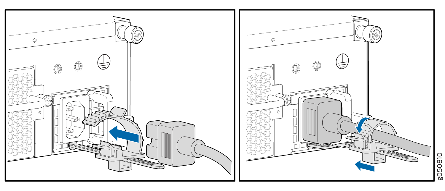
- Attach a power cord retainer to each AC power supply.
See Figure 6.Figure 6: Attaching a Cord Retainer to the AC Power Supply
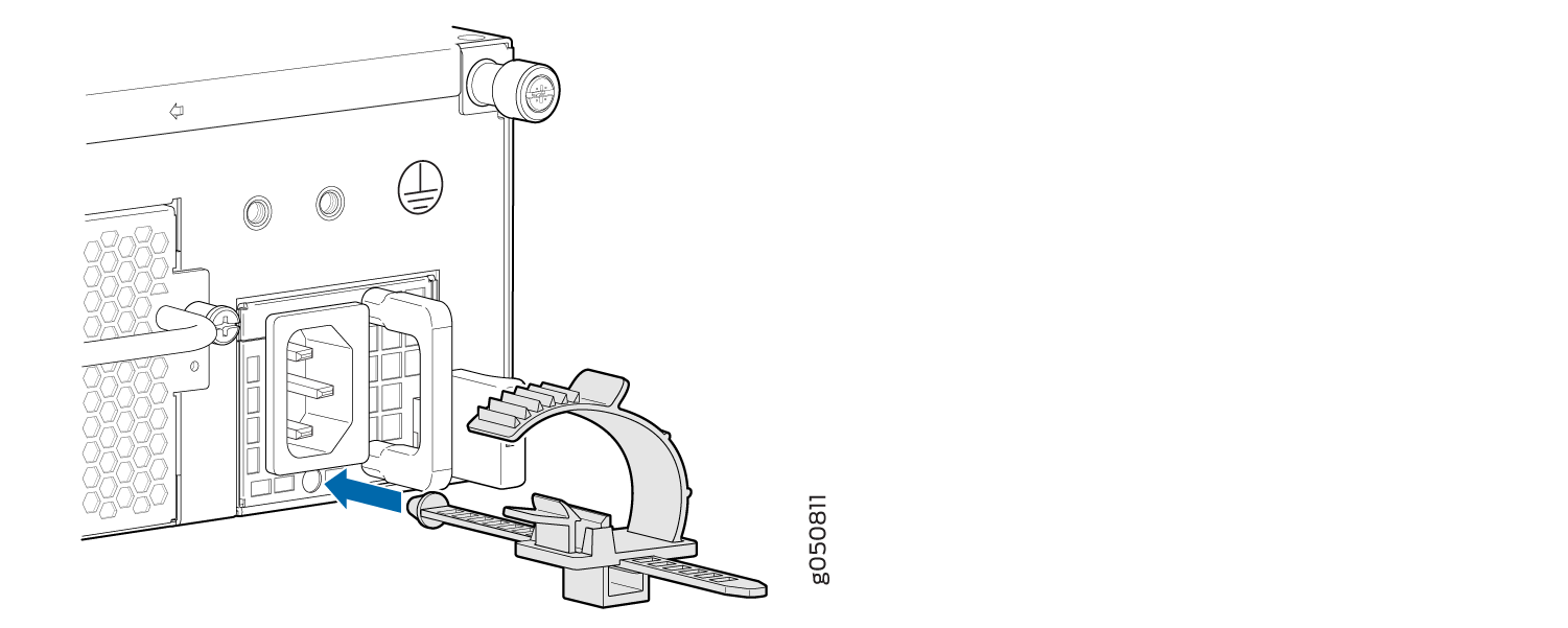
- Push down the power cord retainer to lock the retainer
down over the power cord. Figure 7: Connecting AC Power
See Also
Connecting DC Power to a QFX5210
Before you begin connecting DC power to the switch:
Ensure that you have taken the necessary precautions to prevent electrostatic discharge (ESD) damage (see Prevention of Electrostatic Discharge Damage).
Ensure that you have connected the switch chassis to earth ground.
CAUTION:Before you connect power to the switch, a licensed electrician must attach a cable lug to the grounding and power cables that you supply. A cable with an incorrectly attached lug can damage the switch (for example, by causing a short circuit).
To meet safety and electromagnetic interference (EMI) requirements and to ensure proper operation, you must connect the chassis to earth ground before you connect it to power. For installations that require a separate grounding conductor to the chassis, use the protective earthing terminal on the switch chassis to connect to the earth ground. For instructions on connecting earth ground, see Connecting the QFX5210 to Ground.
Install the power supply in the chassis. For instructions on installing a power supply in a QFX5210, see Installing a Power Supply in a QFX5210.
Ensure that you have the following parts and tools available:
DC power source cables (provided)
Multimeter (not provided)
The QFX5210 is shipped from the factory with two power supplies. Each power supply is a hot-removable and hot-insertable field-replaceable unit (FRU) when the second power supply is installed and running. You can install replacement power supplies in the two slots next to the fan modules without powering off the switch or disrupting the switching function.
A DC-powered QFX5210 is intended for installation only in a restricted access location.
The battery returns of the DC power supply must be connected as an isolated DC return (DC-I).
To connect DC power to a QFX5210:
- The QFX5210 is designed to operate with a DC power supply
that has a single, non-redundant, feed input. For source redundancy,
two DC power supplies must be installed in QFX5210; connect source
(A) to one power supply and connect source (B) to the second power
supply. This configuration provides the commonly deployed A/B feed
redundancy for the system.CAUTION:
The connection between each power source and power supply must include a circuit breaker.
Do not connect two sources to a single power supply because doing so can potentially cause circulating current in feed wires whenever there is any difference in the voltage of the two sources.
Figure 8: DC Power Supply Faceplate for a QFX5210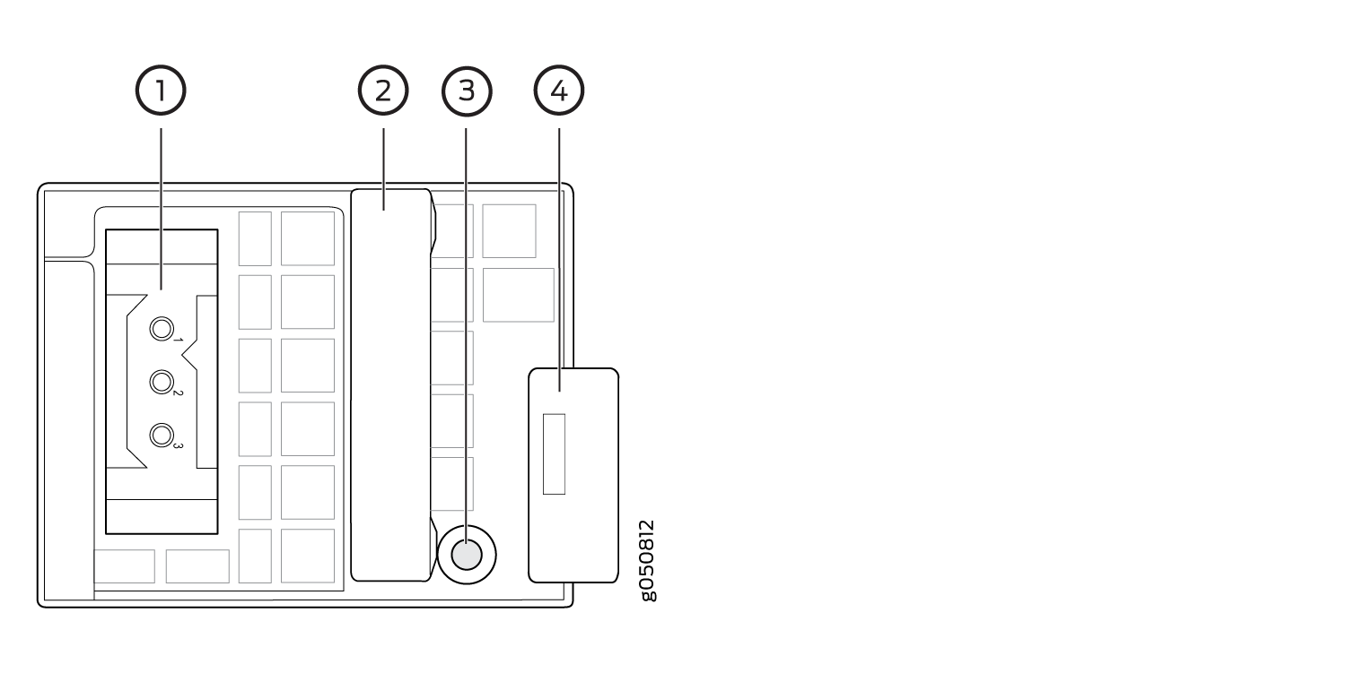 1—
1—Terminal block
3—Fault LED
2—Handle
4—Ejector lever
CAUTION:The V+ terminals are shunted internally together, as are the V- terminals. The same polarity terminal can be wired together from the same source to provide an additional current path in a higher power chassis. Do not connect the terminals to different sources.