Help us improve your experience.

Let us know what you think.

Do you have time for a two-minute survey?


Unpacking and Mounting the QFX5210

Unpacking a QFX5210

The QFX5210 switch chassis is a rigid sheet-metal structure that houses the hardware components. A QFX5210 is shipped in a cardboard carton, secured with foam packing material. The carton also contains an accessory box and quick start instructions.

CAUTION:

The QFX5210 is maximally protected inside the shipping carton. Do not unpack the switch until you are ready to begin installation.

To unpack a QFX5210:

  1. Move the shipping carton to a staging area as close to the installation site as possible, but where you have enough room to remove the system components.
  2. Position the carton so that the arrows are pointing up.
  3. Open the top flaps on the shipping carton.
  4. Remove the accessory box and verify the contents against the inventory included in the box. Table 1 lists the inventory of components supplied with a QFX5210.
  5. Pull out the packing material holding the switch in place.
  6. Verify the chassis components received:
    • Two power supplies

    • Four fan modules

  7. Save the shipping carton and packing materials in case you need to move or ship the switch later.
Table 1: Inventory of Components Supplied with a QFX5210 Device

Component

Quantity

Chassis with four fan modules and two power supplies.

1

Rack mounting kit

  • Front mounting brackets

  • Rear mounting blades

  • Flathead screws

Note:

Spare rack mount kits are ordered as QFX5210-4PST-RMK.

1

  • 2

  • 2

  • 12

Power cords, C15

2

Power cord retainers (AC models only)

2

Documentation roadmap card

1

Warranty

1

Note:

We no longer include a DB-9 to RJ-45 cable or a DB-9 to RJ-45 adapter with a CAT5E copper cable as part of the device package. If you require a console cable, you can order it separately with the part number JNP-CBL-RJ45-DB9 (DB-9 to RJ-45 adapter with a CAT5E copper cable).

Register Products—Mandatory to Validate SLAs

Register all new Juniper Networks hardware products and changes to an existing installed product using the Juniper Networks website to activate your hardware replacement service-level agreements (SLAs).

CAUTION:

Register product serial numbers on the Juniper Networks website. Update the installation base data if any addition or change to the installation base occurs or if the installation base is moved. Juniper Networks is not responsible for not meeting the hardware replacement service-level agreement for products that do not have registered serial numbers or accurate installation base data.

Register your product(s) at https://tools.juniper.net/svcreg/SRegSerialNum.jsp.Update your installation base at https://www.juniper.net/customers/csc/management/updateinstallbase.jsp.

Mounting a QFX5210 in a Rack or Cabinet

You can mount all QFX5210 switches on a four post 19-in. rack or cabinet using the mounting kit provided with the switch.

For four post rack or cabinet installations, the mounting kit contains two front mounting rails with two matching rear mounting blades. This configuration allows either end of the switch to be mounted flush with the rack and still be adjustable for racks with different depths.

The mounting kit for the QFX5210-64C has mounting rails, blades, and brackets for the four-post configuration.

(The remainder of this topic uses “rack” to mean “rack or cabinet.”) The front and rear rack rails must be spaced between 28 in. (71.1 cm) and 36 in. (91.4 cm) front to back.

This topic describes:

Before You Begin Rack Installation

Before you begin mounting a QFX5210 switch in the rack or cabinet:

  1. Ensure that you understand how to prevent electrostatic discharge (ESD) damage. See Prevention of Electrostatic Discharge Damage.
  2. Verify that the site meets the requirements described in QFX5210 Site Guidelines and Requirements.
  3. Place the rack in its permanent location, allowing adequate clearance for airflow and maintenance, and secure it to the building structure.
  4. Read General Site Guidelines, and QFX5210 Installation Overview..
  5. Remove the switch from the shipping carton (see Unpacking and Mounting the QFX5210).
  6. Ensure that you have the following parts and tools available to mount the switch in a rack:
    • ESD grounding strap (not provided).

    • Blades, rails, or brackets (provided).

      Warning:

      Only use Juniper-provided rack mounting kits to ensure proper ventilation and cooling to the chassis.

      • For four-post installations:

        • One pair of rear mounting blades. These mounting blades support the rear of the chassis and must be installed (provided).

        • One pair of front mounting rails. The mounting blades slide into the mounting rails to support the switch (provided).

        • Screws to secure the mounting rails to the chassis (provided).

          • Twelve M4 flat-head screws for attaching the mounting bracket to the chassis.

        • Eight screws to secure the chassis and rear installation blades to the rack (not provided).

    • Appropriate screwdriver for the mounting screws (not provided).

    • Two power cords with plugs appropriate to your geographical location (provided).

    • RJ-45 cable and RJ-45 to DB-9 serial port adapter (not provided).

    • Management host, such as a PC laptop, with a serial port (not provided).

    Note:

    We no longer include a DB-9 to RJ-45 cable or a DB-9 to RJ-45 adapter with a CAT5E copper cable as part of the device package. If you require a console cable, you can order it separately with the part number JNP-CBL-RJ45-DB9 (DB-9 to RJ-45 adapter with a CAT5E copper cable).

  7. Register the QFX5210. SeeRegister Products—Mandatory to Validate SLAs

Optional equipment: Grounding cable kit with bracket, lug, and three nuts with integrated washers.

Warning:

A QFX5210 must be supported at all four corners. Mounting the chassis using only the front brackets will damage the chassis and can result in serious bodily injury.

CAUTION:

All QFX5210 require two people for installation, one person to lift the device into place and another person to attach it to the rack. If you are installing the QFX5210 above 60 in. (152.4 cm) from the floor, you can remove the power supplies and fan modules to minimize the weight before attempting to install the device.

CAUTION:

If you are mounting multiple devices on a rack, mount the device in the lowest position of the rack first. Proceed to mount the rest of the devices from the bottom to the top of the rack to minimize the risk of the rack toppling.

Four Post Procedure

To mount the switch on four posts in a rack using the provided mounting kit:

  1. Attach the ESD grounding strap to your bare wrist and to a site ESD point.
  2. Decide whether the Field Replaceable Unit (FRU) end of the switch or the port end is to be placed at the front of the rack. Position the switch in such a manner that the AIR IN labels on components are next to the cold aisle and AIR OUT labels on components are next to the hot aisle.
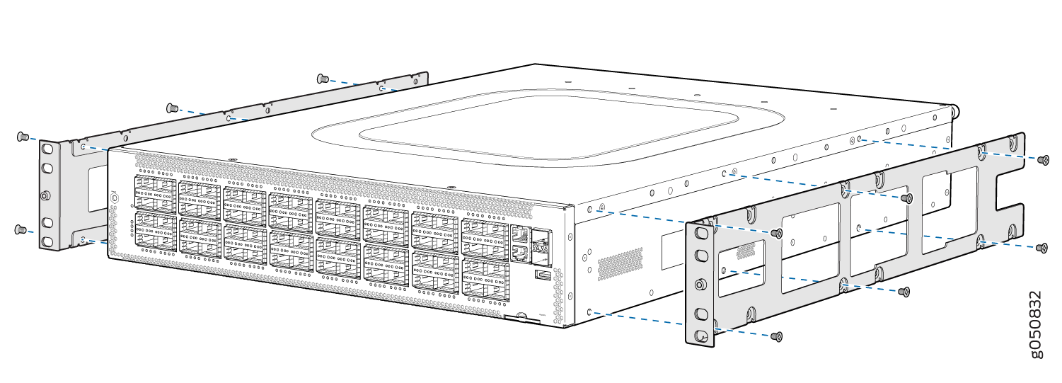
  3. Align the holes in the mounting rail with the holes on the side of the chassis. SeeFigure 1 to see the proper alignment for the QFX5210.
    Figure 1: Attaching Mounting Rails to the QFX5210Attaching Mounting Rails to the QFX5210
  4. Attach the mounting rail to the switch using the mounting screws. Tighten the screws.
  5. Repeats steps 3 and 4 on the opposite side of the switch.
  6. Have one person grasp both sides of the switch, lift it, and position it in the rack so that the front bracket is aligned with the rack holes.
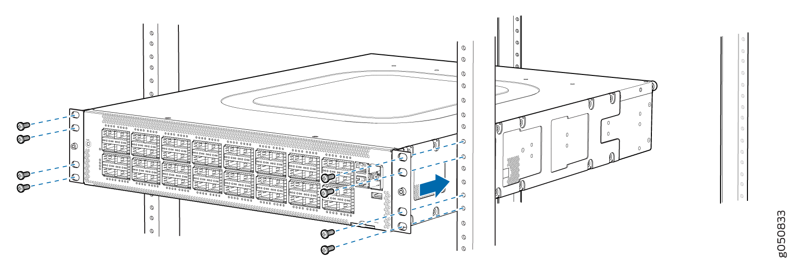
  7. Have a second person secure the front of the switch to the rack using four mounting screws (and cage nuts and washers if your rack requires them.) Tighten the screws. See Figure 2 for an example of attaching the chassis with mounting rail to the mounting rack.
    Figure 2: Attach Chassis to the Mounting RackAttach Chassis to the Mounting Rack
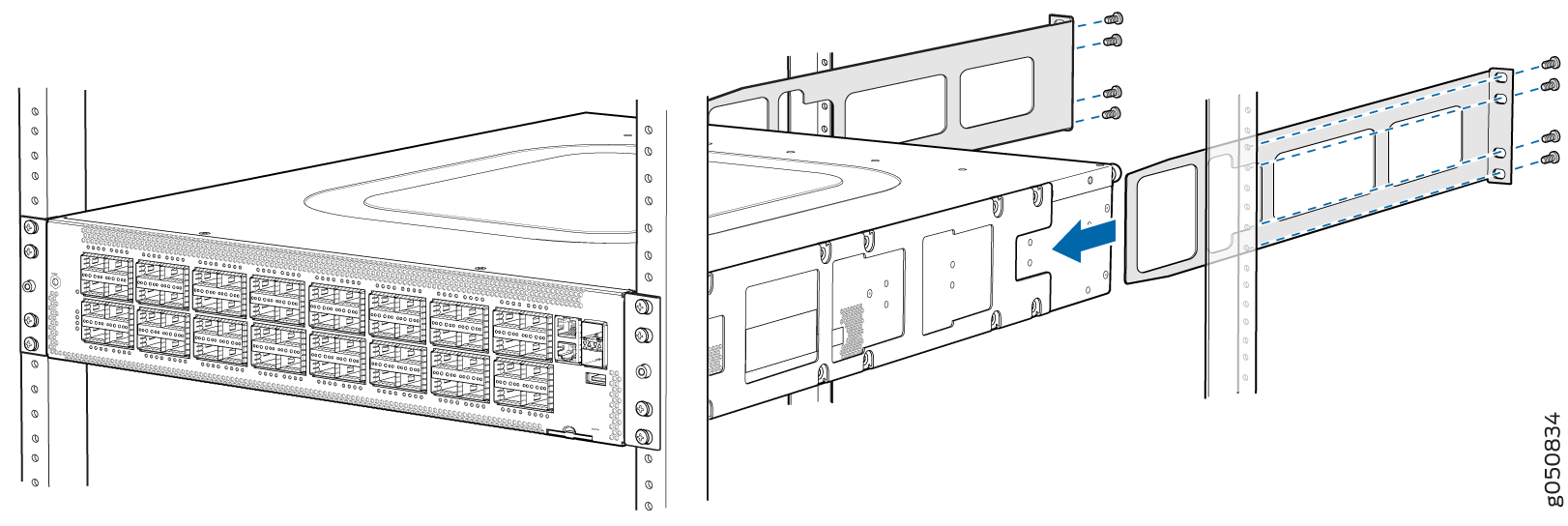
  8. Continue to support the switch while sliding the rear mounting-blades into the channel of the side mounting-rails and securing the blades to the rack. Use the four mounting screws (and cage nuts and washers if your rack requires them) to attach each blade to the rack. (Use eight front-mounting screws for the QFX5210.)Tighten the screws. See Figure 3.
    Figure 3: Slide Mounting Blade into Mounting RailSlide Mounting Blade into Mounting Rail
  9. Ensure that the switch chassis is level by verifying that all the screws on the front of the rack are aligned with the screws at the back of the rack.