Unpack and Mount the QFX5130 Switch
Unpack a QFX5130 Switch
The QFX5130 chassis is a rigid sheet-metal structure that houses the hardware components. A QFX5130 switch is shipped in a cardboard carton, secured with foam packing material.
The QFX5130 switch is maximally protected inside the shipping carton. Do not unpack the switch until you are ready to begin installation.
To unpack a QFX5130 switch:
- Move the shipping carton to a staging area as close to the installation site as possible, but where you have enough room to remove the system components.
- Position the carton so that the arrows are pointing up.
- Open the top flaps on the shipping carton.
- Pull out the packing material holding the switch in place.
- Verify the contents against the inventory included in the box. Table 1 lists the inventory of components supplied with a QFX5130-32CD/QFX5130E-32CD.
- Save the shipping carton and packing materials in case you need to move or ship the switch later.
|
Component |
Quantity |
|---|---|
|
Chassis |
1 |
|
Fan modules |
6, factory installed |
|
Power supplies
|
2, factory installed |
|
Rack mount kit - QFX5K-4PST-RMK-E QFX5K-4PST-RMK-E rack mount kit consists of the following parts:
Spare rack mount kits order numbers:
|
1 |
|
Rack mount assembly drawing |
1 |
|
Power cords with plugs appropriate to your geographical location |
2 |
|
Documentation roadmap card |
1 |
|
Warranty |
1 |
|
Component |
Quantity |
|---|---|
|
Chassis |
1 |
|
Fan modules |
6, factory installed |
|
Power supplies
|
2, factory installed |
|
Rack mount kit - QFX5130-1RU-4PRMK |
1 |
|
Rack mount assembly drawing |
1 |
|
Power cords with plugs appropriate to your geographical location |
2 |
|
Documentation roadmap card |
1 |
|
Warranty |
1 |
We no longer include the RJ-45 console cable with the DB-9 adapter as part of the device package. If the console cable and adapter are not included in your device package, or if you need a different type of adapter, you can order the following separately:
- RJ-45 to DB-9 adapter (JNP-CBL-RJ45-DB9)
- RJ-45 to USB-A adapter (JNP-CBL-RJ45-USBA)
- RJ-45 to USB-C adapter (JNP-CBL-RJ45-USBC)
If you want to use RJ-45 to USB-A or RJ-45 to USB-C adapter you must have X64 (64-Bit) Virtual COM port (VCP) driver installed on your PC. See, https://ftdichip.com/drivers/vcp-drivers/ to download the driver.
Update Base Installation Data
Update the installation base data if any addition or change to the installation base occurs or if the installation base is moved. Juniper Networks is not responsible for not meeting the hardware replacement SLA for products that do not have accurate installation base data.
Update your installation base at https://supportportal.juniper.net/s/CreateCase .
Mount the QFX5130-32CD/QFX5130E-32CD by Using the QFX5K-4PST-RMK-E Rack Mount Kit
You can mount a QFX5130-32CD/QFX5130E-32CD switch on a square hole or threaded hole four-post 19-in. rack by using the partial tool-less QFX5K-4PST-RMK-E rack mount kit (RMK) that is shipped along with the product, as default.
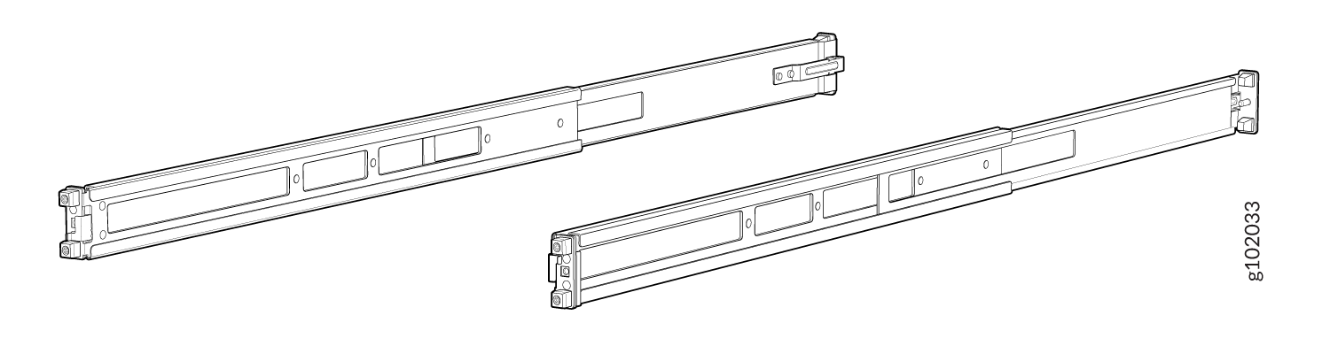
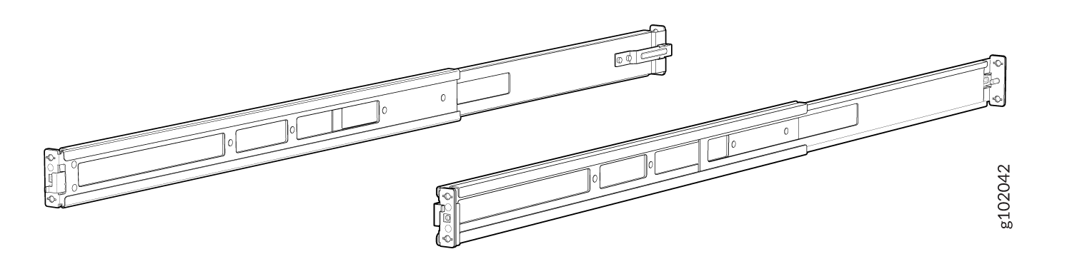
The QFX5K-4PST-RMK-E rack mount kit consists of the following parts:
-
A pair of front and rear-mounting rails
-
A pair of mounting brackets
-
16 flat-head M4 x 6mm Phillips screws
-
A pair of spacers
A four-post installation evenly supports the device by all four corners.
- Mount the Device by Using the QFX5K-4PST-RMK-E Rack Mount Kit On a Square Hole Rack
- Mount the Device by Using the QFX5K-4PST-RMK-E Rack Mount Kit On a Threaded Hole Rack
- Mount QFX5130-32CD/QFX5130E-32CD on a Four-Post Rack Using the QFX5220-32CD-4PRMK Rack Mount Kit
- Mount QFX5130-32CD/QFX5130E-32CD on a Four-Post Cabinet
- Mount the QFX5130-48C/QFX5130-48CM Switch by Using the QFX5130-1RU-4PRMK Rack Mount Kit on a Square Hole Rack
- Mount Your QFX5130-48C/QFX5130-48CM Switch by Using the QFX5130-1RU-4PRMK Rack Mount Kit on a Threaded-Hole Four-Post Rack
Mount the Device by Using the QFX5K-4PST-RMK-E Rack Mount Kit On a Square Hole Rack
Ensure that you have the following tools and parts available:
-
An ESD grounding strap—not provided.
-
Number 2 Phillips (+) screwdriver—not provided
-
A pair of front and rear mounting rails. These mounting rails attach to the front and rear rack posts—provided with the rack mount kit
-
A pair of side mounting brackets and 16 flat head M4 x 6mm Phillips screws. These brackets attach to the device if not pre-installed—provided with the rack mount kit
-
A pair of Spacers—provided with the rack mount kit
To mount the device on four posts in a rack by using the QFX5K-4PST-RMK-E rack mount kit:
- Assemble the mounting rails.
-
Attach the mounting rails to the rack.
-
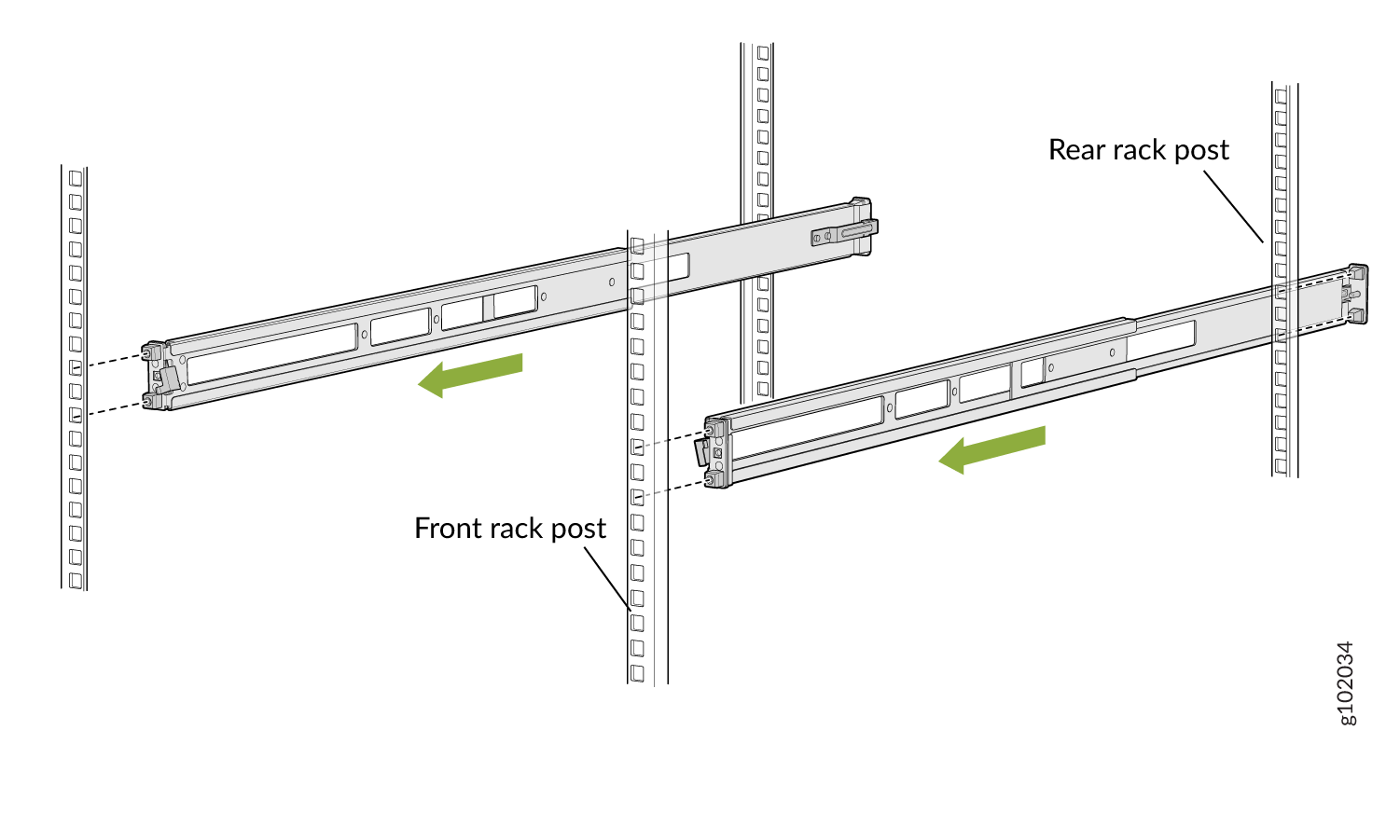
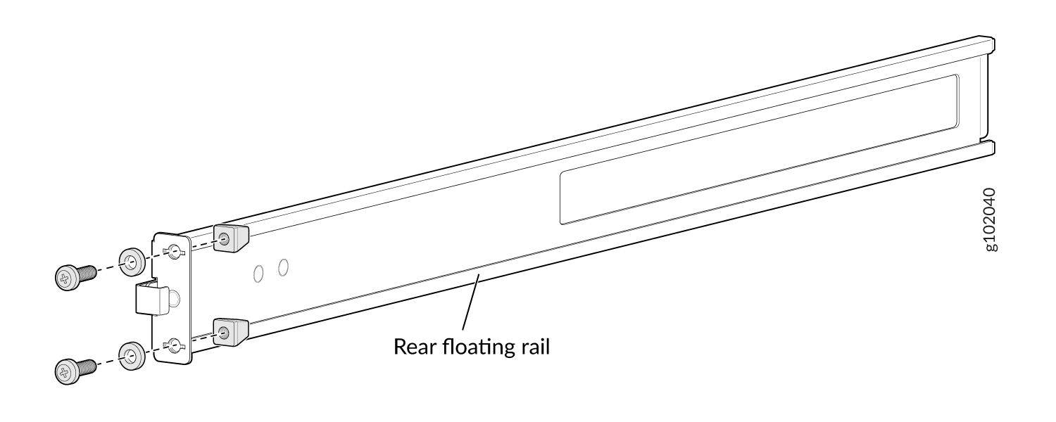
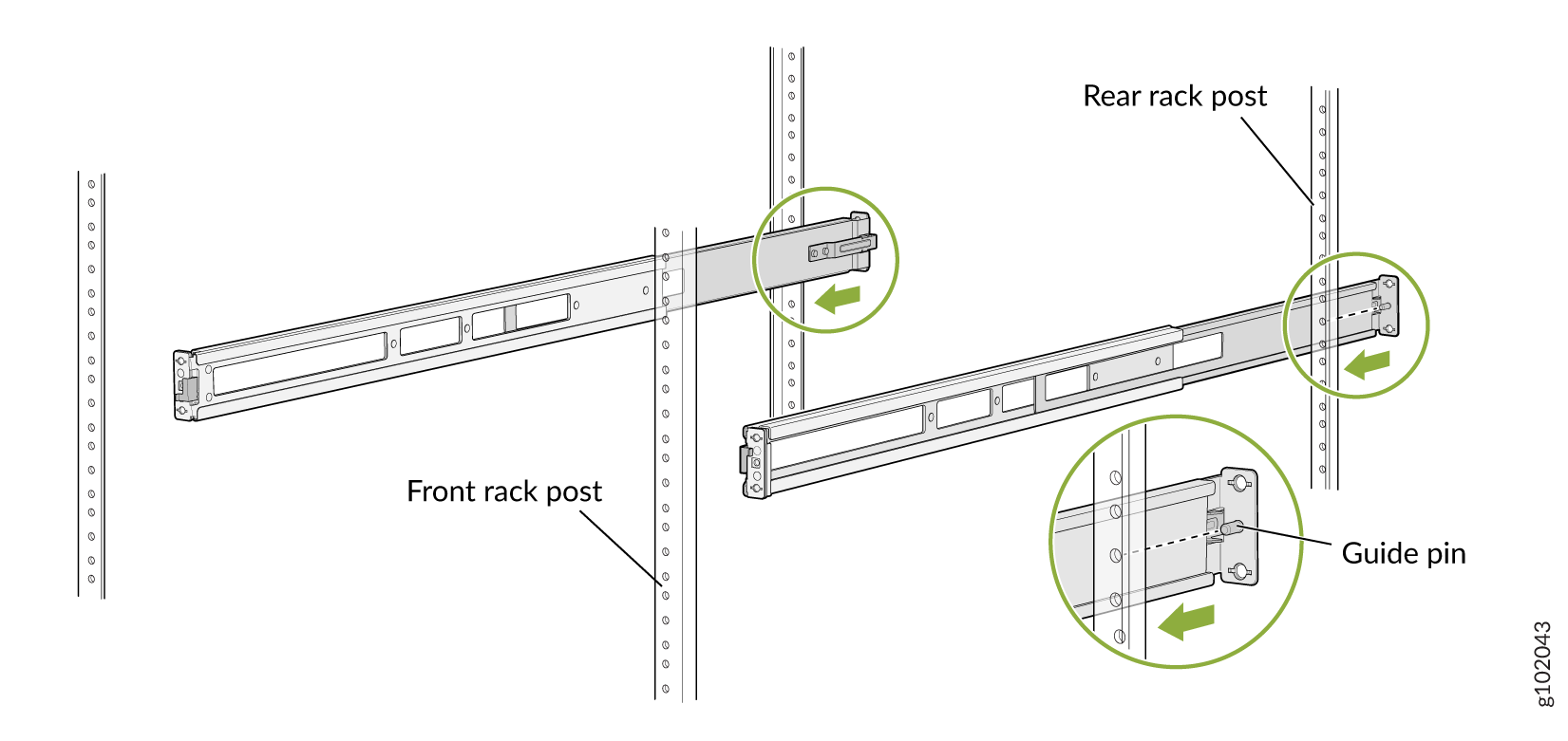
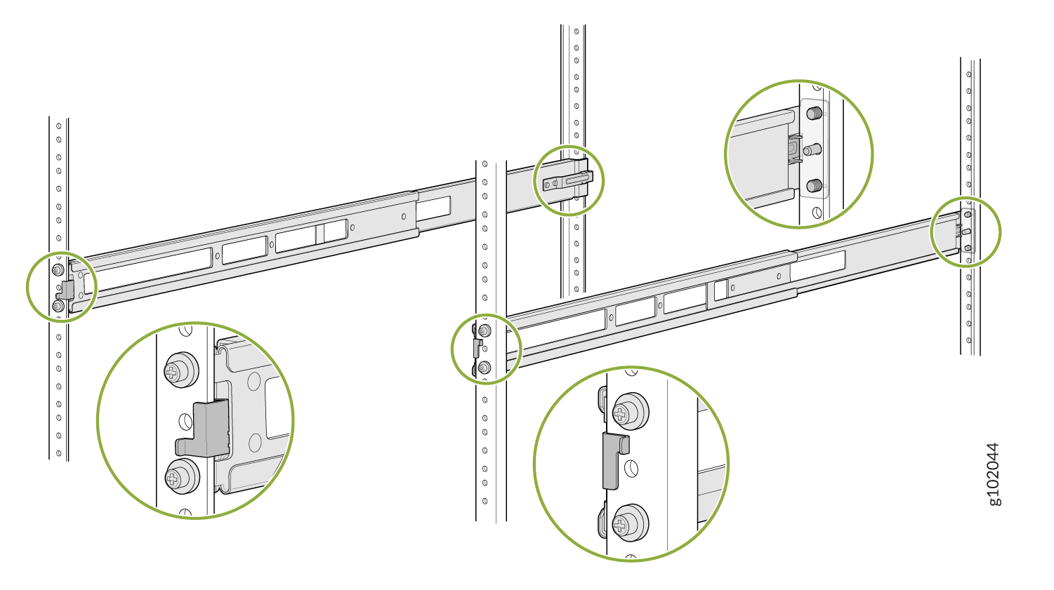
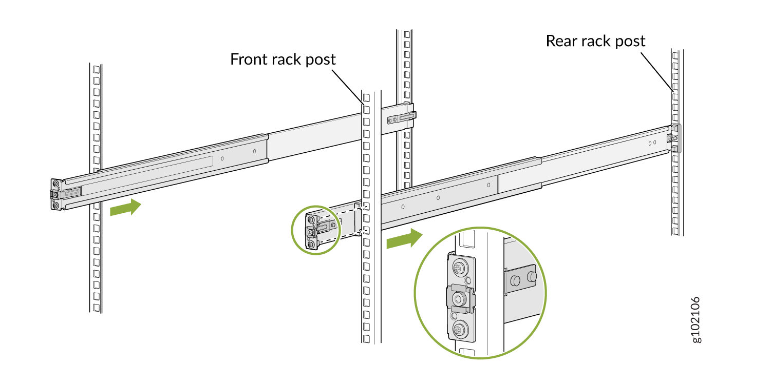
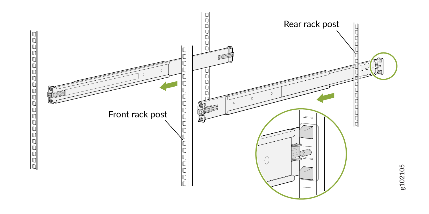
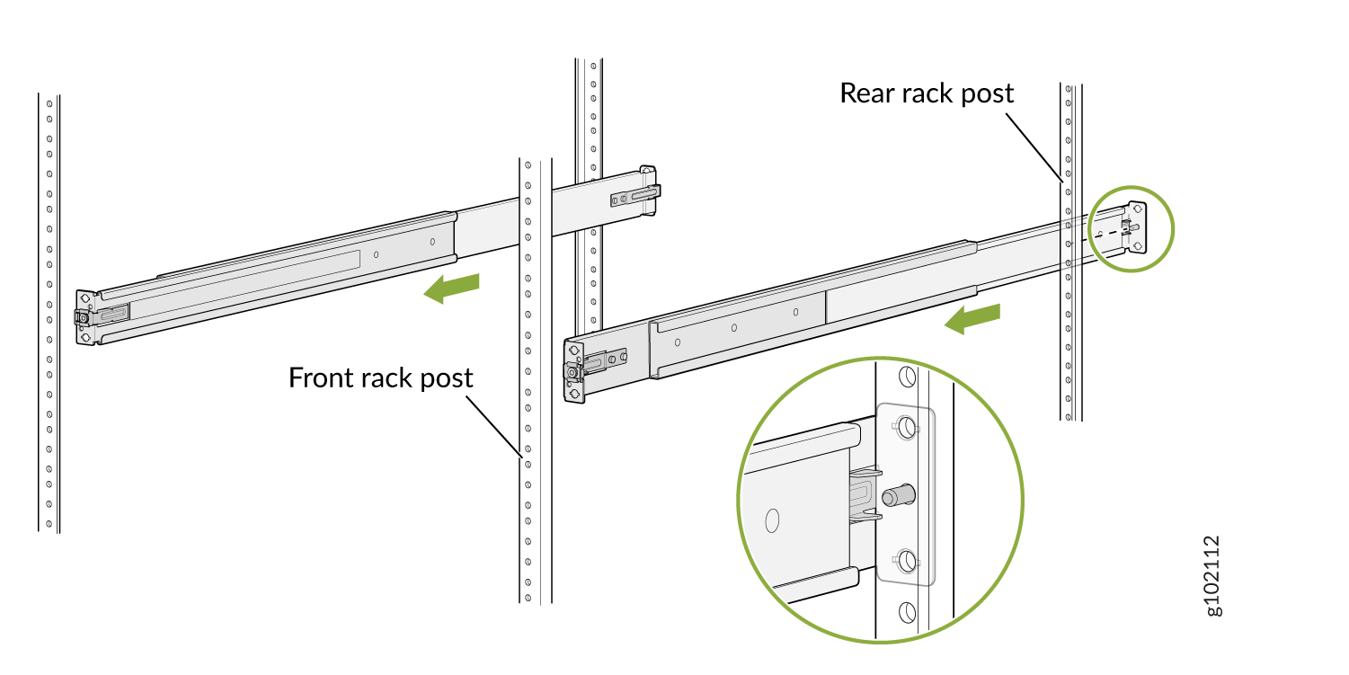
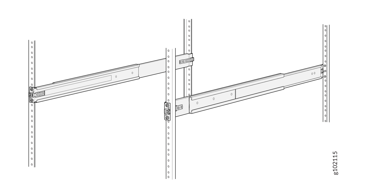
Standing in front of the rack, align the guide blocks of the rear mounting rails
with the rear-post holes. Pull the rear mounting rails toward the front of the rack to
lock the rails in place. You will hear a click sound when the latch locks into the
corresponding rack holes. See Figure 3.
Figure 3: Install the Rear Floating Rails
-
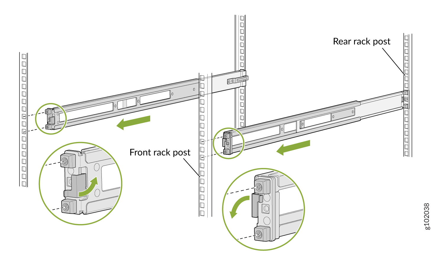
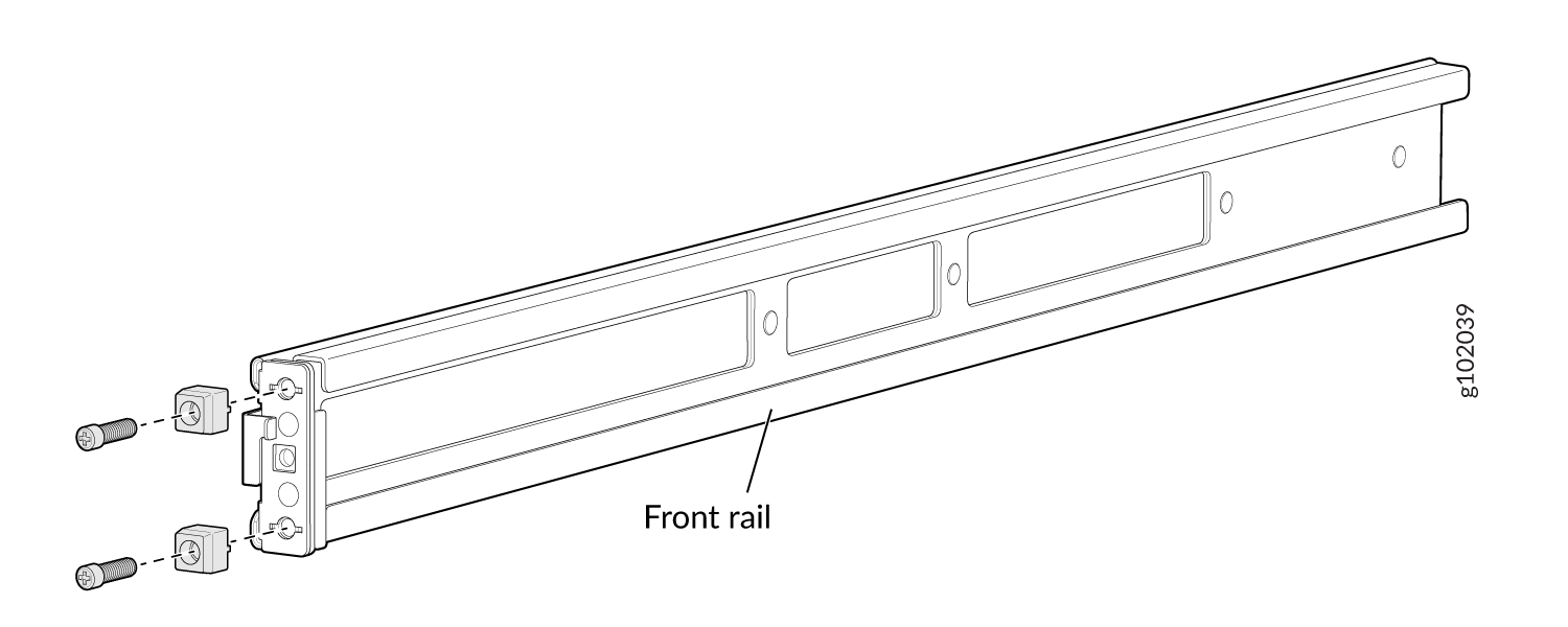
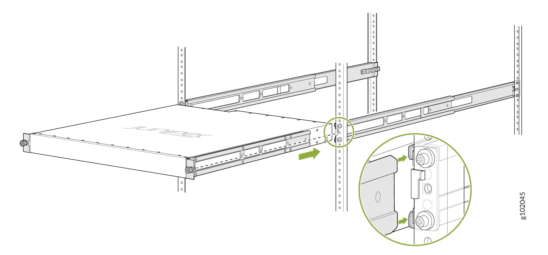
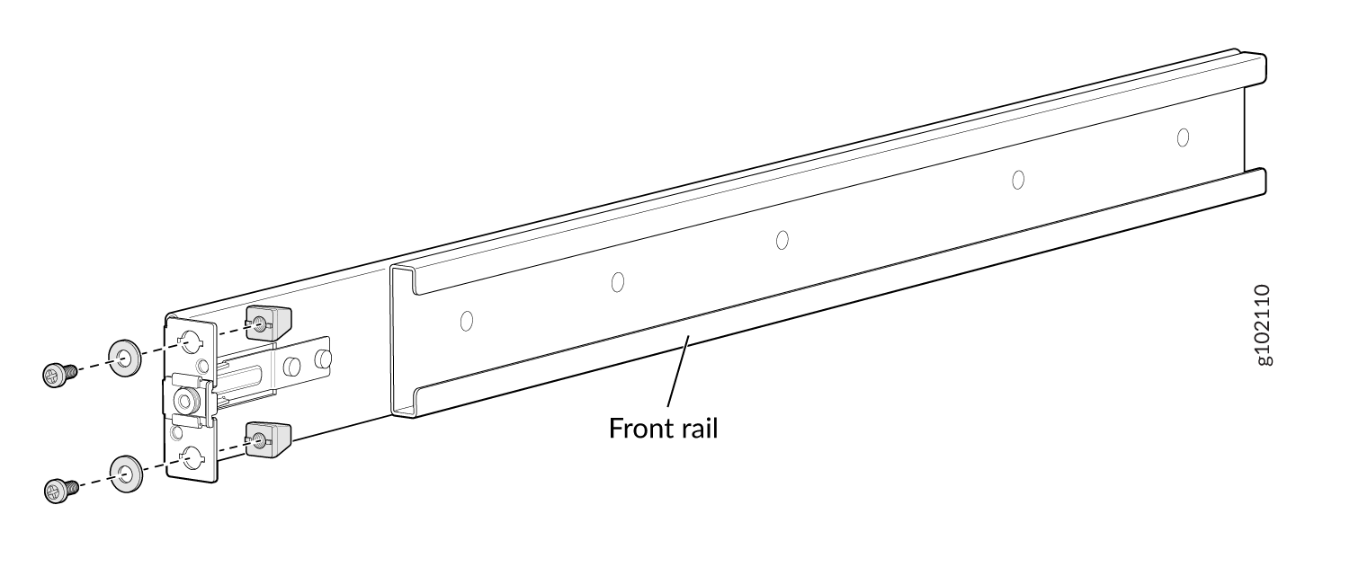
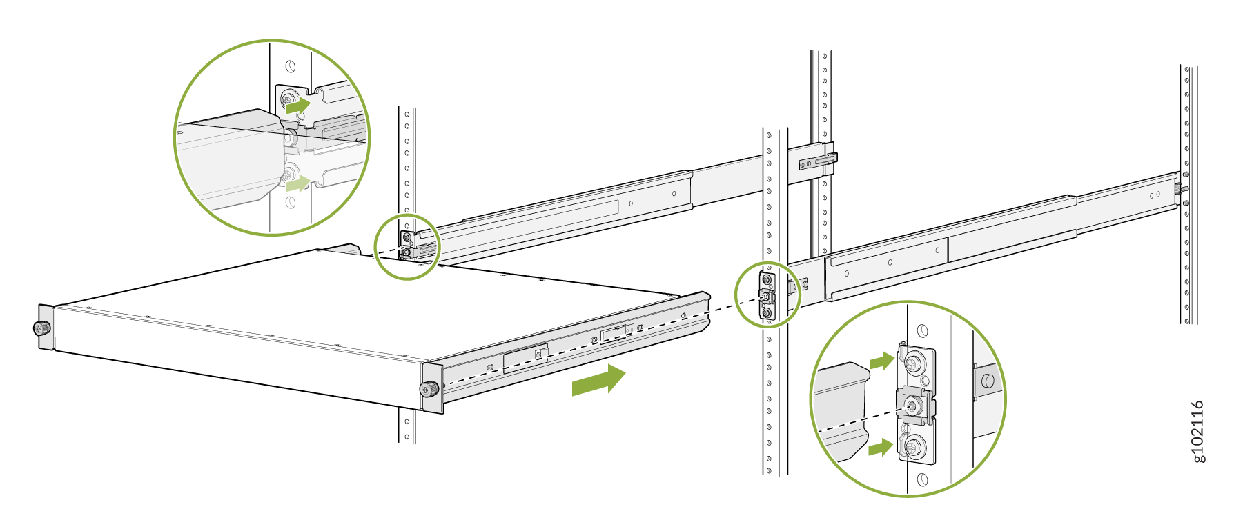
Move the latch lock on the front mounting rail to open position, slide the front
mounting rail, and insert the guide blocks into the front rack posts. See Figure 4.
Figure 4: Install the Front Mounting Rails
-
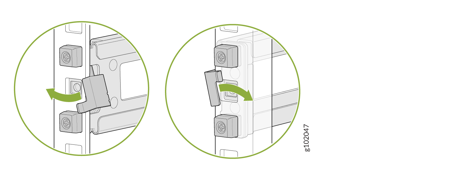
Push the lock latch to the locked position. See Figure 5.
Figure 5: Front Mounting Rail's Lock Latch
-
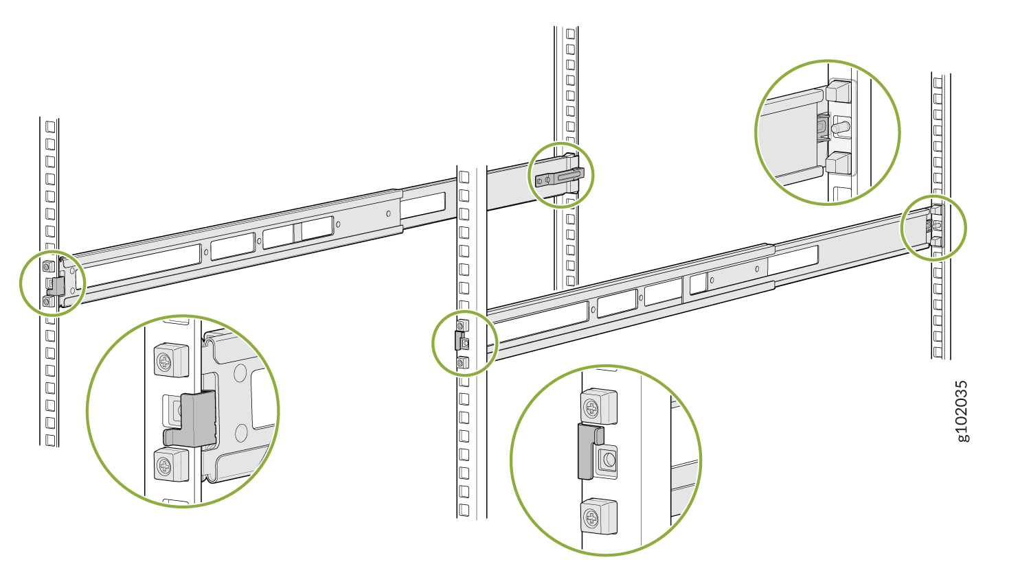
Visually ensure that the front and rear latches are locked into place on the
mountingrails. See Figure 6.
Figure 6: Mounting Rails Installed and Locked
-
Standing in front of the rack, align the guide blocks of the rear mounting rails
with the rear-post holes. Pull the rear mounting rails toward the front of the rack to
lock the rails in place. You will hear a click sound when the latch locks into the
corresponding rack holes. See Figure 3.
-
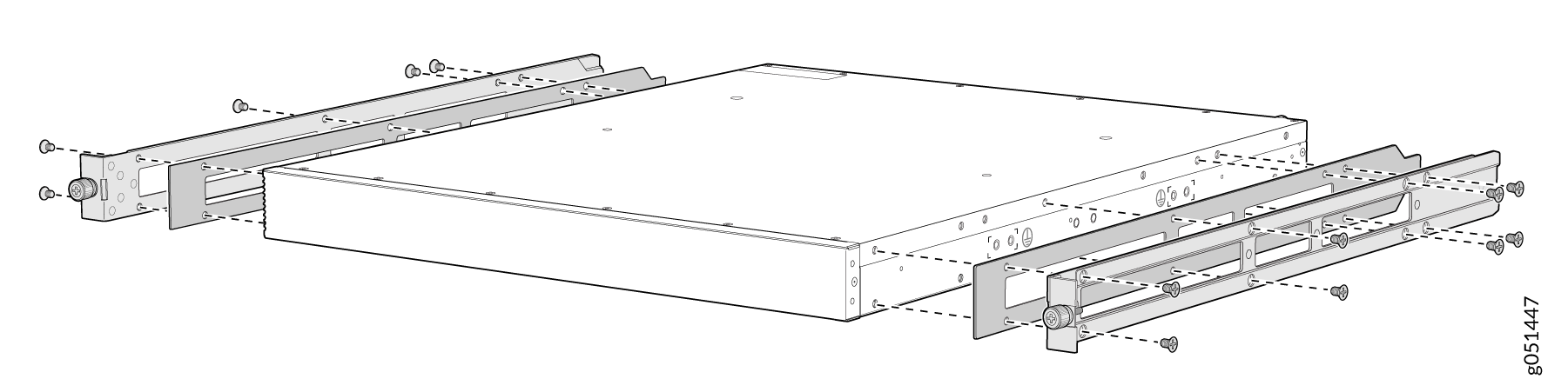
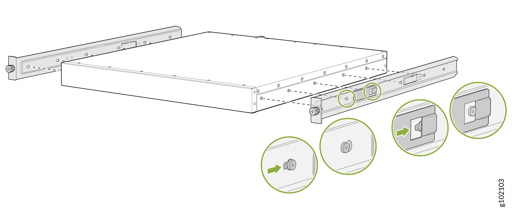
Attach the spacers and the mounting brackets to the device if not pre-installed. If
your device already has the spacers and mounting brackets pre-installed than skip this
step and move to the next step.
-
Insert the flat head M4 x 6mm Phillips screws to attach the spacer and the mounting
bracket into the aligned holes on the chassis (see Figure 7). Tighten the screws.
Figure 7: Attach the Spacers and the Mounting Brackets to the Device
-
Insert the flat head M4 x 6mm Phillips screws to attach the spacer and the mounting
bracket into the aligned holes on the chassis (see Figure 7). Tighten the screws.
-
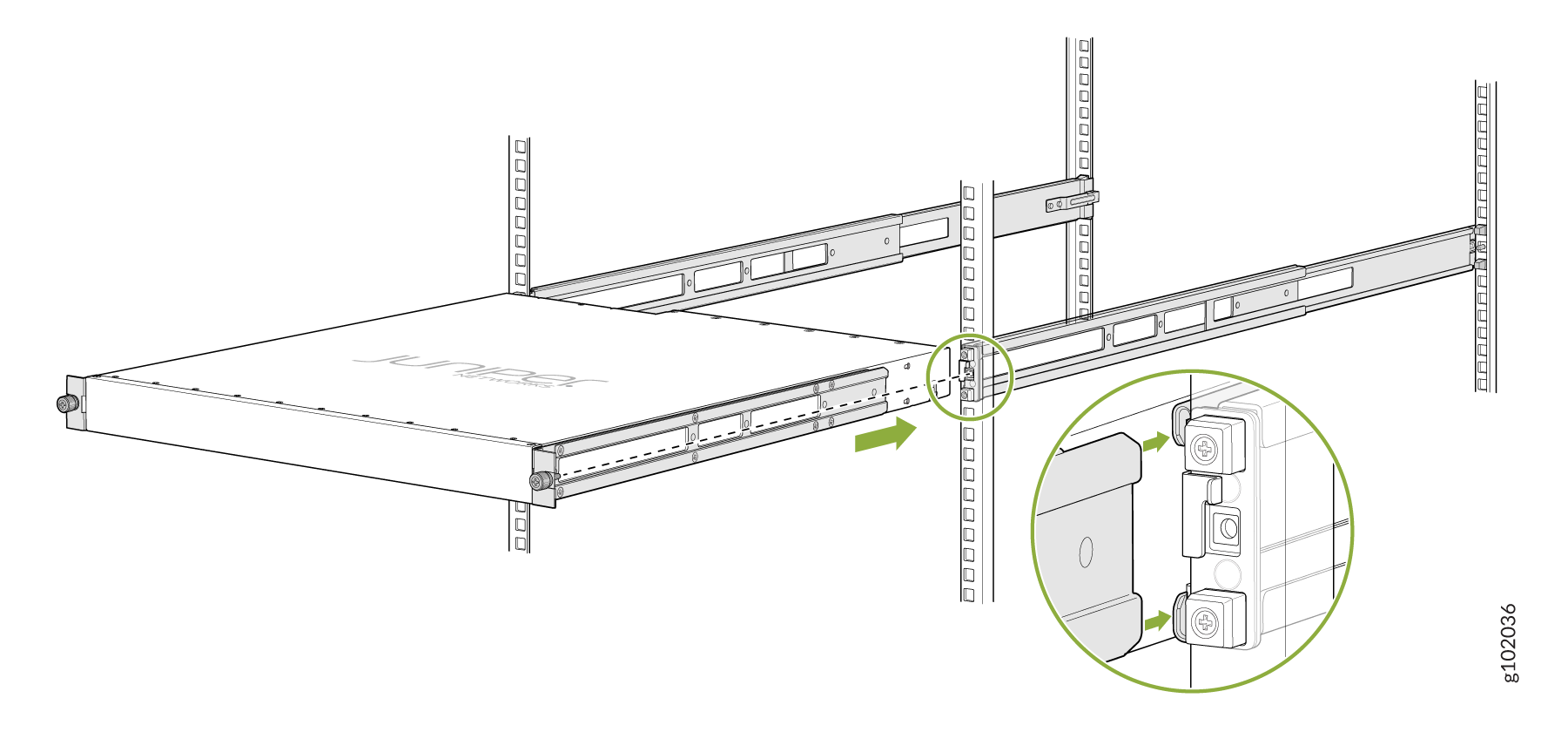
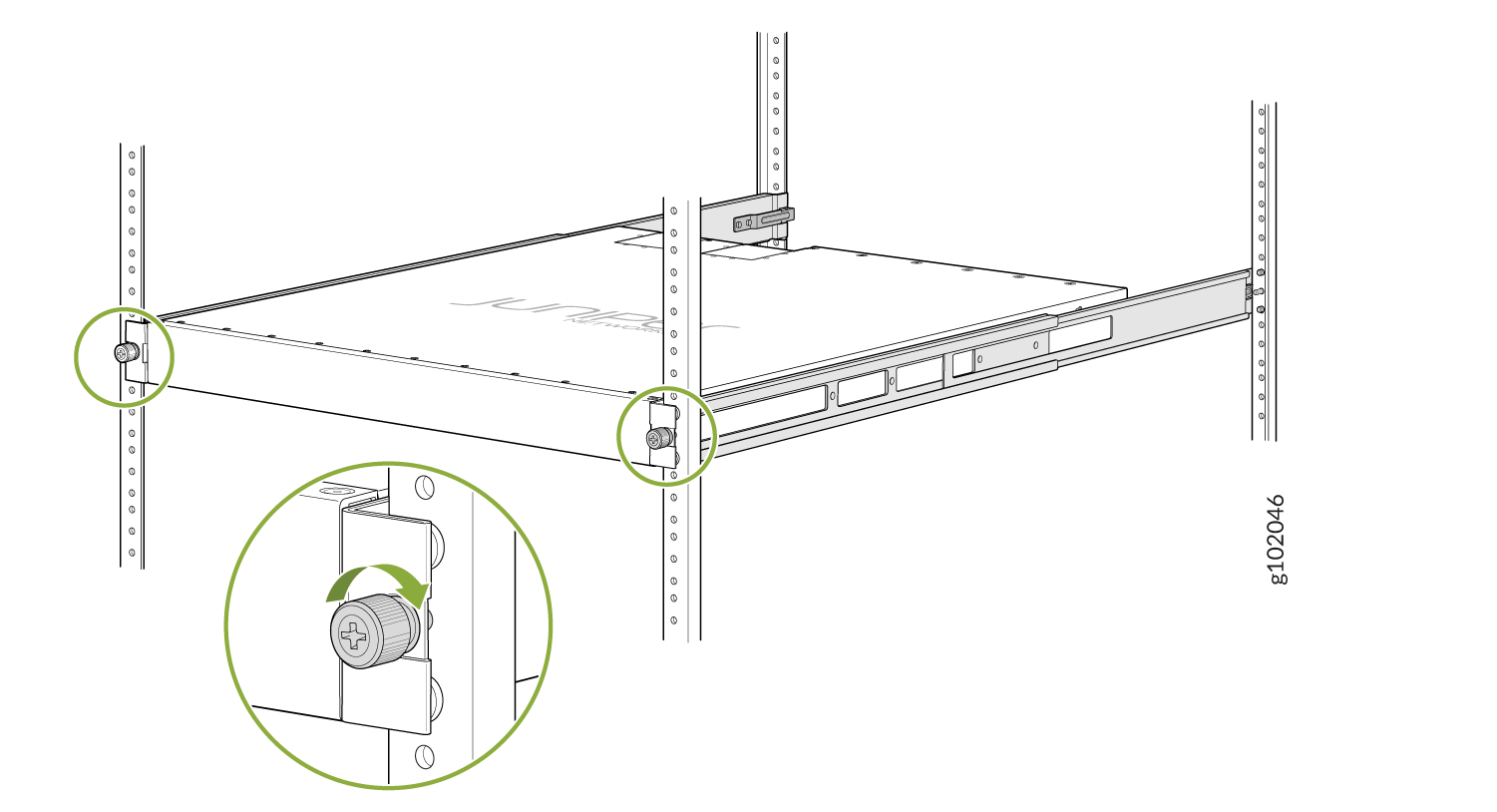
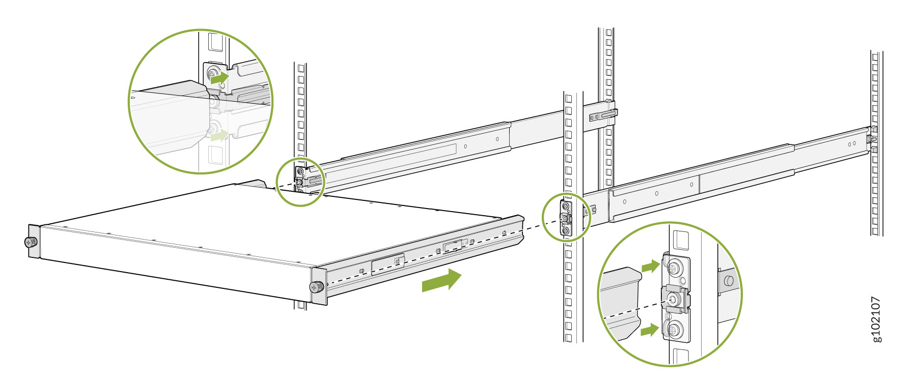
Lift the device and position it in the rack, aligning the side mounting brackets with
the mounting rails. Slide the device into the channels of the rack mounting rails. See
Figure 8.
Figure 8: Slide the Device into the Rack
-
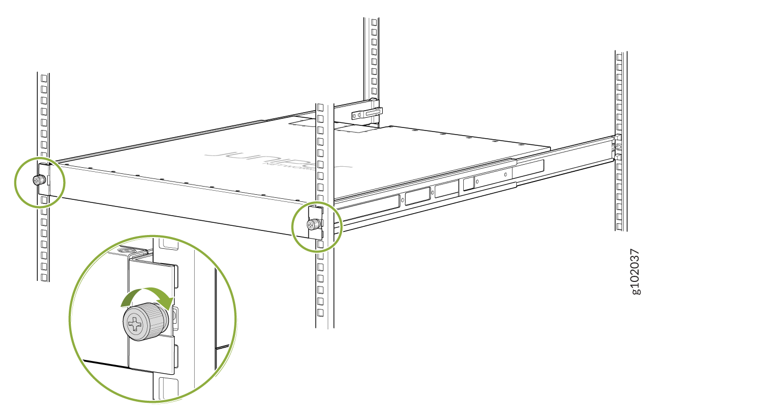
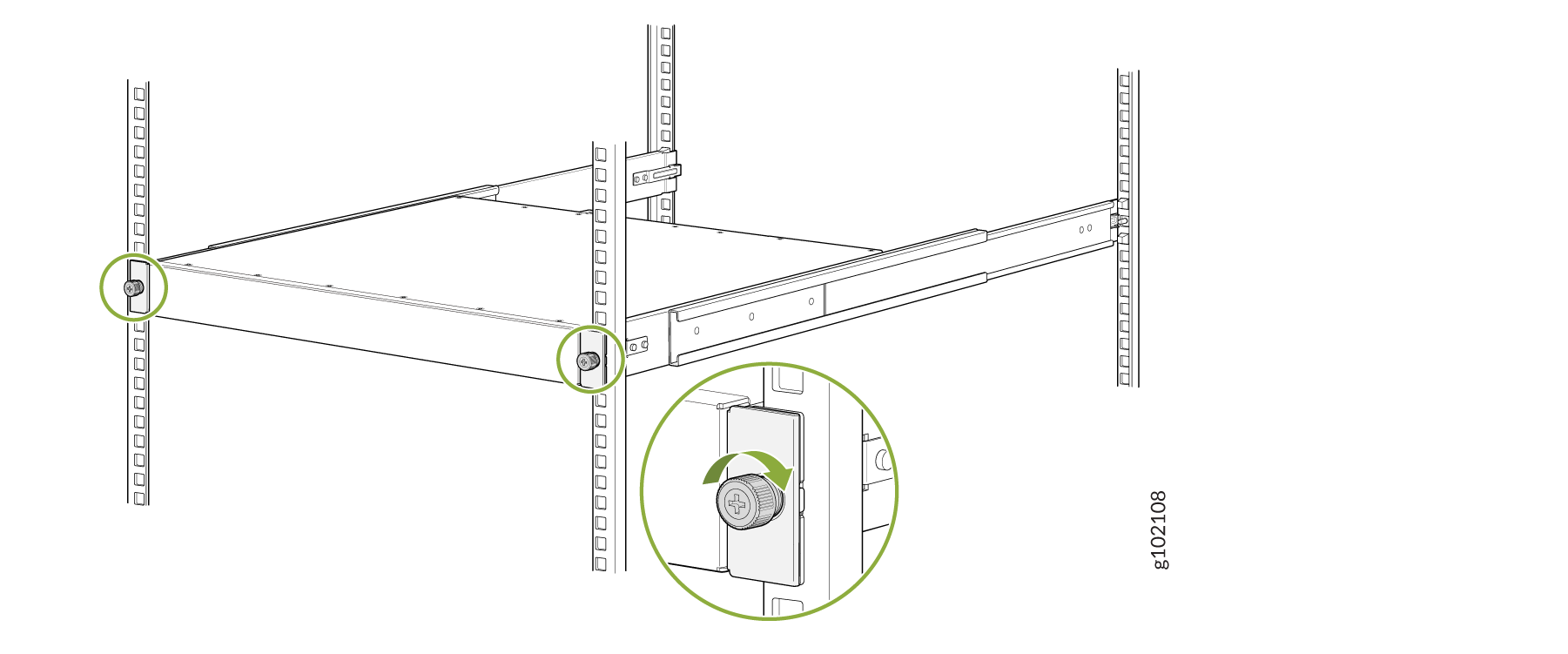
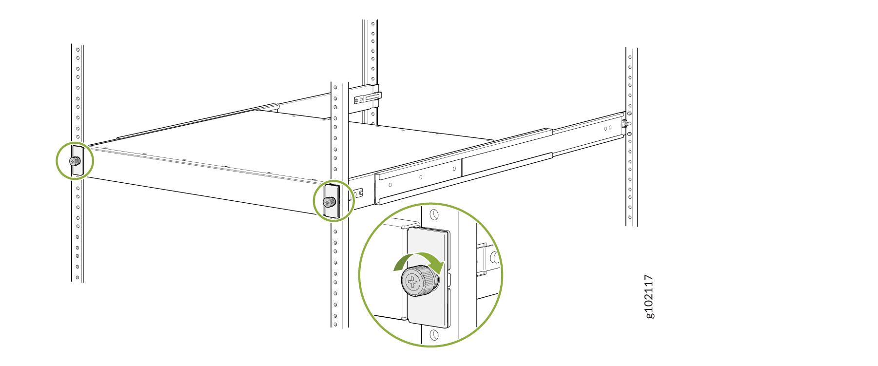
Tighten the two thumbscrews to secure the device. See Figure 9.
Figure 9: Tighten Thumb Screws
Mount the Device by Using the QFX5K-4PST-RMK-E Rack Mount Kit On a Threaded Hole Rack
Ensure that you have the following tools and parts available:
-
An ESD grounding strap—not provided.
-
Number 2 Phillips (+) screwdriver—not provided
-
A pair of front and rear mounting rails. These mounting rails attach to the front and rear rack posts—provided with the rack mount kit
-
A pair of side mounting brackets and 16 flat head M4 x 6mm Phillips screws. These brackets attach to the device if not pre-installed—provided with the rack mount kit
-
A pair of Spacers—provided with the rack mount kit
To mount the device on a four-post rack with threaded holes:
-
Assemble the mounting rails.
-
Remove the guide blocks from the front mounting rails by loosening the screws and
preserve them for later use. See Figure 10.
Figure 10: Remove Guide Blocks from Front Mounting Rail
-
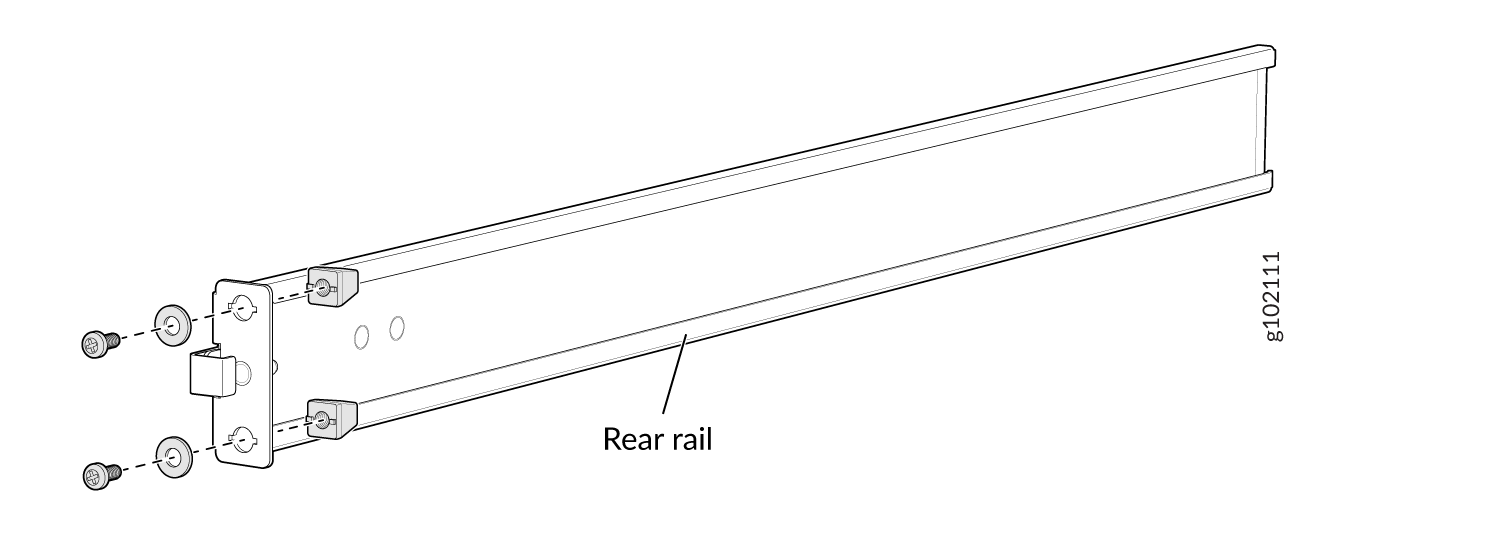
Remove the guide blocks from the rear floating rails by loosening the screws and
washers. Preserve the guide blocks, screws, and washers for later use. See Figure 11
Figure 11: Remove Guide Blocks from Rear Floating Rail
-
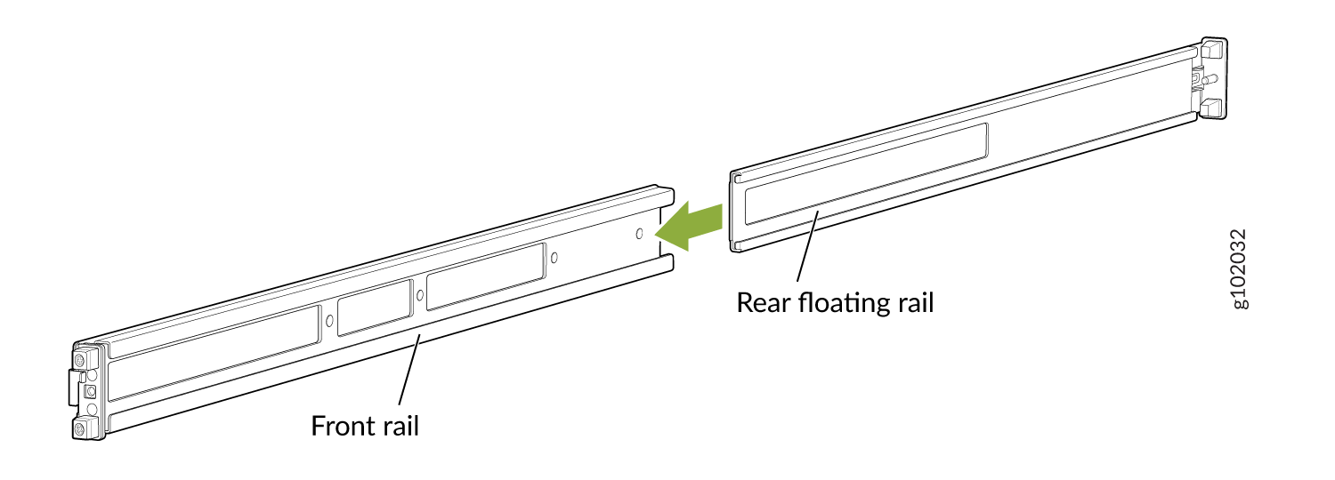
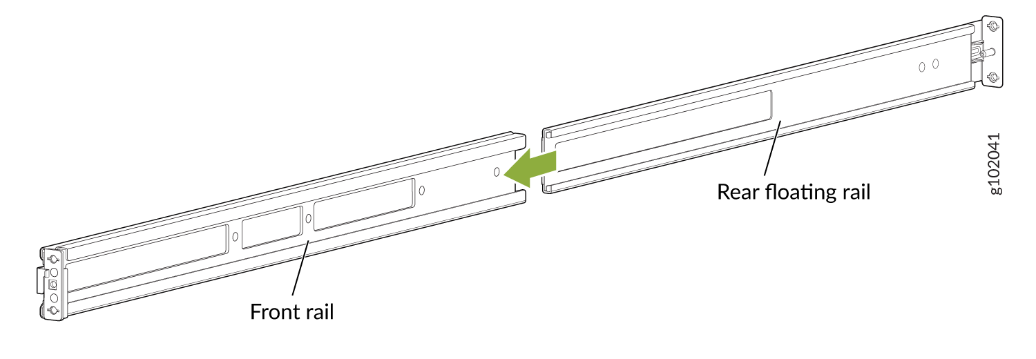
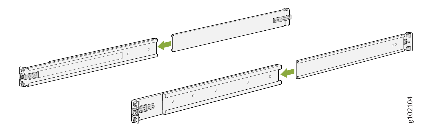
Slide the rear floating rails into the front mounting rails. See Figure 12.
Figure 12: Slide Rear Floating Rail into Front Mounting Rail
-
Mounting rails assembled. See Figure 13.
Figure 13: Front and Rear Rails Assembled
-
Remove the guide blocks from the front mounting rails by loosening the screws and
preserve them for later use. See Figure 10.
-
Attach the mounting rails to the threaded hole rack.
-
Standing in front of the rack, align the guide blocks of the rear mounting rails
with the rear-post holes. Pull the rear mounting rails toward the front of the rack to
lock the rails in place. You will hear a click sound when the latch locks into the
corresponding rack holes. See Figure 14.
Figure 14: Install the Rear Floating Rails
-
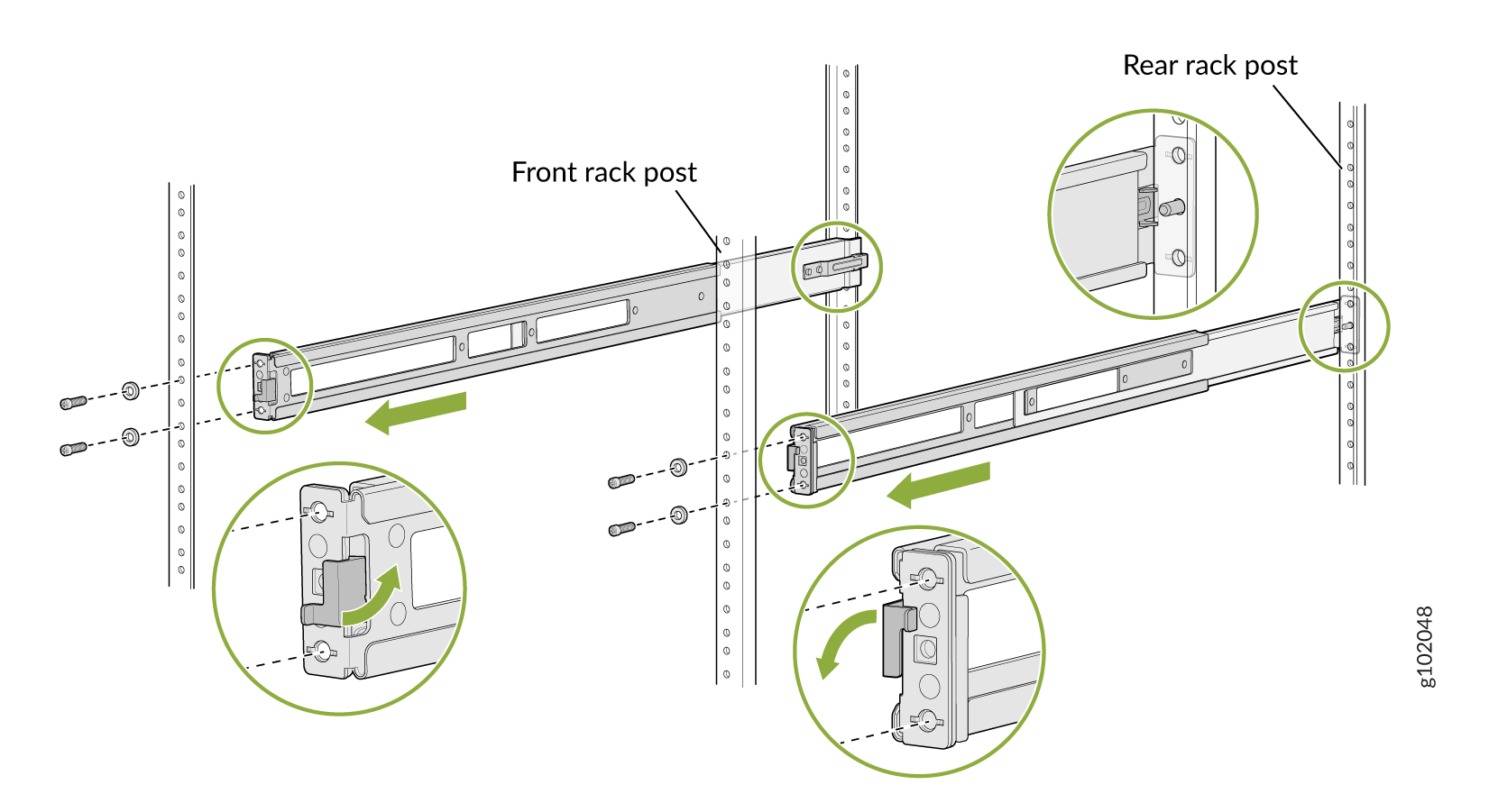
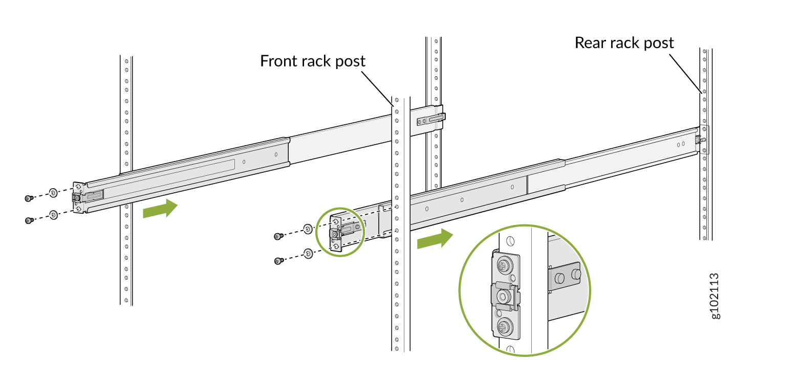
Move the latch lock on the front mounting rail to open position, slide the front
mounting rail and position it to the front rack post. Push the lock latch to locked
position and using the screws removed in step 2.a and
the washers removed in step 2.b
secure the front mounting rails to the front rack post. See Figure 15.
Figure 15: Install the Front Mounting Rails
-
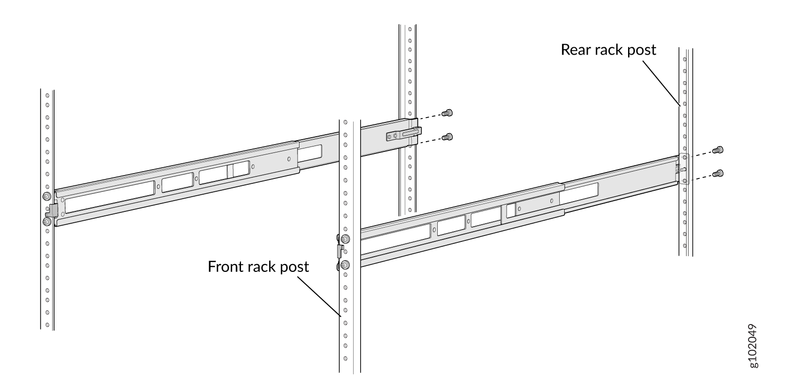
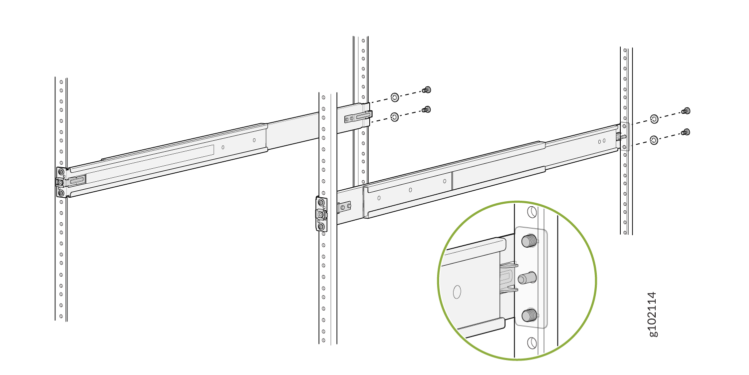
Secure the rear floating rail to the rear rack post by using screws (not provided)
appropriate for your rack threaded size. See Figure 16.
Figure 16: Secure the Rear Floating Rail
-
Visually ensure that the front and rear latches are locked into place on the
mounting rails. See Figure 17.
Figure 17: Mounting Rails Installed and Secured
-
Standing in front of the rack, align the guide blocks of the rear mounting rails
with the rear-post holes. Pull the rear mounting rails toward the front of the rack to
lock the rails in place. You will hear a click sound when the latch locks into the
corresponding rack holes. See Figure 14.
-
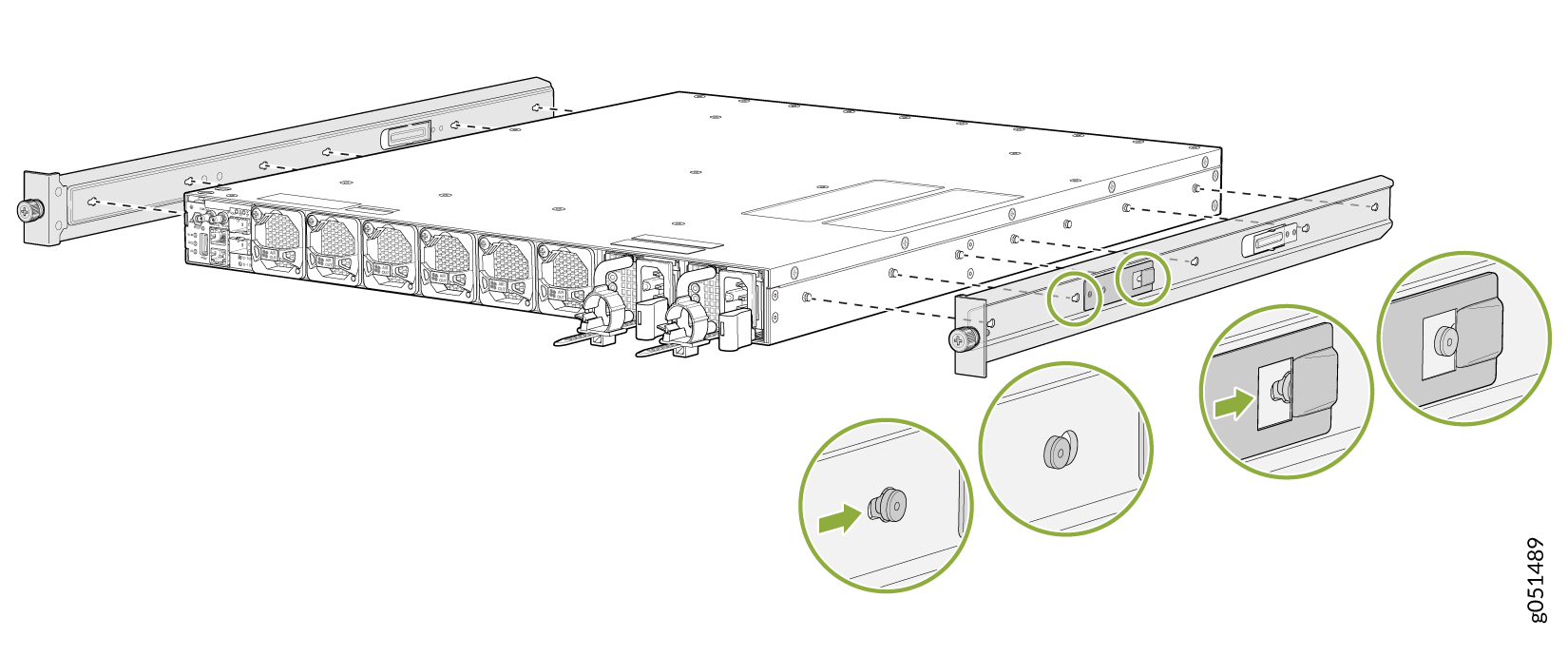
Attach the spacers and the mounting brackets to the device if not pre-installed. If
your device already has the spacers and mounting brackets pre-installed than skip this
step and move to the next step.
-
Insert the flat head M4 x 6mm Phillips screws to attach the spacer and the mounting
bracket into the aligned holes on the chassis (see Figure 18). Tighten the screws.
Figure 18: Attach the Spacers and the Mounting Brackets to the Device
-
Insert the flat head M4 x 6mm Phillips screws to attach the spacer and the mounting
bracket into the aligned holes on the chassis (see Figure 18). Tighten the screws.
-
Lift the device and position it in the rack, aligning the side mounting brackets with
the mounting rails. Slide the device into the channels of the rack mounting rails. See
Figure 19.
Figure 19: Slide the Device into the Rack
-
Tighten the two thumbscrews to secure the device. See Figure 20.
Figure 20: Tighten the Thumb Screws
Mount QFX5130-32CD/QFX5130E-32CD on a Four-Post Rack Using the QFX5220-32CD-4PRMK Rack Mount Kit
To mount the QFX5130-32CD/QFX5130E-32CD on a four-post rack by using the QFX5220-32CD-4PRMK rack mount kit:
-
If you receive a switch that has preassembled mounting rails attached
to it, you can skip Step 4, Step 5, and Step 6. See Figure 21
.
Figure 21: Pre-attached Mounting Rails on the QFX5130-32CD/QFX5130E-32CD
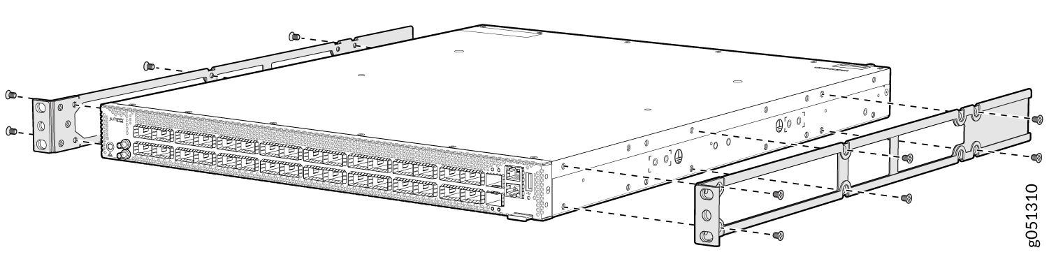
-
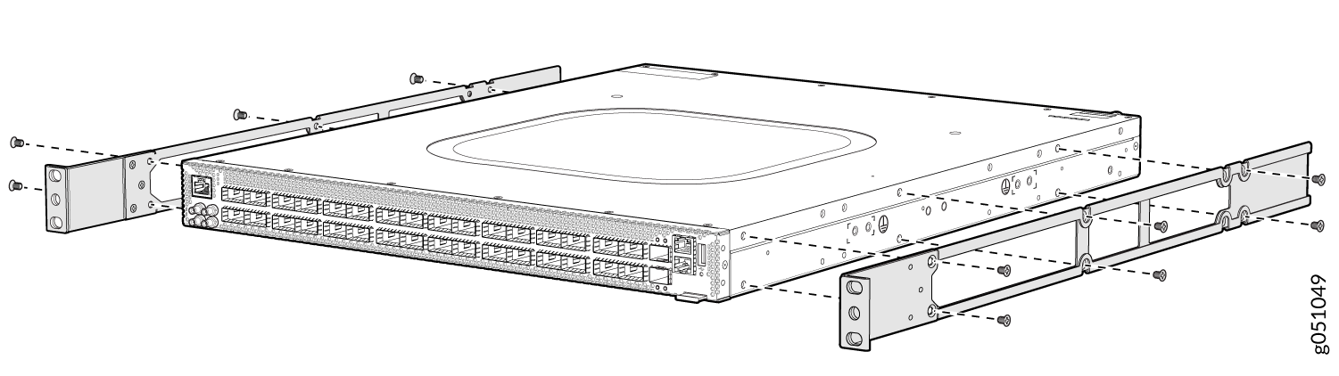
Align the holes in the mounting rail with the holes on the side of the
chassis. See Figure 22 to see
the proper alignment for QFX5130-32CD/QFX5130E-32CD.
Figure 22: Attach Mounting Rails to the QFX5130-32CD/QFX5130E-32CD
-
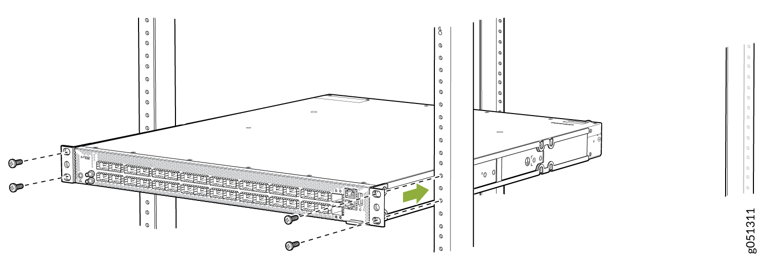
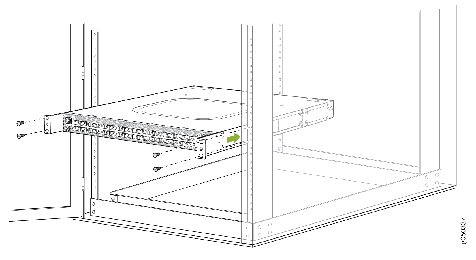
Have a second person secure the front of the switch to the rack by
using four mounting screws (and cage nuts and washers if your rack
requires them.) Tighten the screws. See Figure 23 for an example of
connecting the mounting rails and blades to a
QFX5130-32CD/QFX5130E-32CD.
Figure 23: Attach QFX5130-32CD/QFX5130E-32CD to the Rack
-
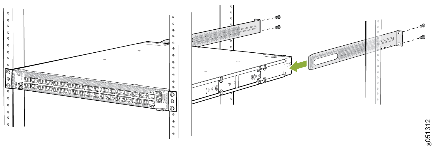
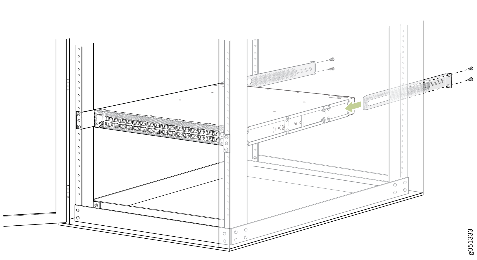
Continue to support the switch while sliding the rear-mounting blades
into the channel of the side-mounting rails and securing the blades to
the rack. Use the four mounting screws (and cage nuts and washers if
your rack requires them) to attach each blade to the rack. Tighten the
screws. See Figure 24.
Figure 24: Sliding Mounting Blade into the Mounting Rail
Mount QFX5130-32CD/QFX5130E-32CD on a Four-Post Cabinet
You can mount a QFX5130-32CD/QFX5130E-32CD on four-post racks within a cabinet. For cabinet installations, you need to reconfigure the provided mounting rail. You must change the mounting rail from a flush-mount to a set-back design to allow room in the cabinet for network cabling. To mount a QFX5130-32CD/QFX5130E-32CD on a four-post cabinet:
-
Disassemble one of the front-mounting rails by removing the three
Phillips screws. See Figure 25 for the rail assembly.
Figure 25: Disassemble the Front-Mounting Rail
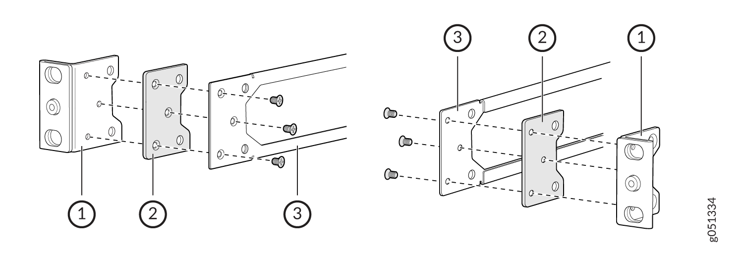 1—
1—Front-mounting bracket (you may discard for this procedure)
3—Mounting rail
2—Spacer
-
Assemble the extended mounting rail by substituting the extension
bracket for the front-mounting bracket. See Figure 26 for the order of the components.
Figure 26: Assemble the Extended Mounting Rail
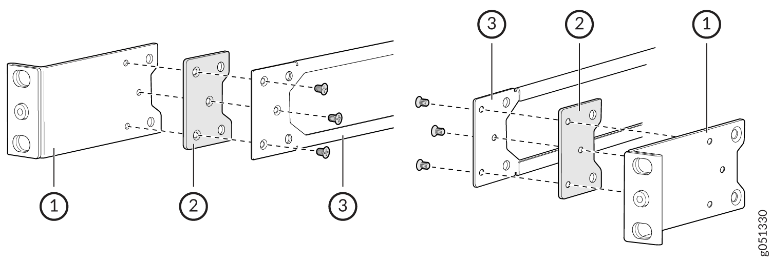 1—
1—Front extension bracket
3—Mounting rail
2—Spacer
- Align the holes in the mounting rail with the holes in the spacer and the extension bracket. The spacer is placed between the extension bracket and the mounting rail, with the mounting rail closest to the chassis.
- Attach the extension bracket and spacer to the mounting rail using the flat-head Phillips machine screws from the original assembly. Tighten the screws by using a Phillips number 2 screwdriver.
- Repeat Step 3 through Step 6 to complete two extended mounting rails.
-
Align the holes in the extended mounting rail with the holes on the
side of the chassis. See Figure 27 to understand the proper alignment for the
QFX5130-32CD/QFX5130E-32CD.
Figure 27: Attach the Mounting Rails to the QFX5130-32CD/QFX5130E-32CD
-
Have a second person secure the front of the switch to the rack by
using four mounting screws (and cage nuts and washers if your rack
requires them.) Tighten the screws. See Figure 28 for an example of attaching the switch and mounting assembly to the
cabinet rack.
Figure 28: Attach QFX5130-32CD/QFX5130E-32CD to Cabinet Rack
-
Continue to support the switch while sliding the rear-mounting blades
into the channel of the extended mounting rails and securing the
mounting blades to the rack. Use four mounting screws (and cage nuts and
washers if your rack requires them) to attach each blade to the rack.
Tighten the screws. See Figure 29.
Figure 29: Sliding the Mounting Blade into the Extended Mounting Rail
Mount the QFX5130-48C/QFX5130-48CM Switch by Using the QFX5130-1RU-4PRMK Rack Mount Kit on a Square Hole Rack
Ensure that you have the following tools and parts available:
-
An ESD grounding strap (not provided)
-
A pair of front and rear mounting rails
These mounting rails attach to the front and rear rack posts (provided with the RMK).
-
A pair of side-mounting brackets—provided with the RMK
You must attach these brackets to the device.
To mount the device on four posts in a rack by using the QFX5130-1RU-4PRMK rack mount kit:
- Wrap and fasten the ESD grounding strap to your bare wrist, and connect the other end of the strap to the ESD point on the device.
- Assemble the mounting rails.
-
Attach the mounting rails to the rack.
-
Standing in front of the rack, align the guide blocks of the
rear-mounting rails with the rear-post holes. Pull the
rear-mounting rails toward the front of the rack to lock the
rails in place. You will hear a click sound when the latch locks
into the corresponding rack holes. See Figure 32.
Figure 32: Install the Rear Floating Rails
-
Move the latch lock on the front-mounting rail to open
position, slide the front- mounting rail, and insert the guide
blocks into the front rack posts. See Figure 33.
Figure 33: Attach the QFX5130-48C Chassis to the Rack
-
Push the lock latch to the locked position. See Figure 34.
Figure 34: Front Mounting Rail's Lock Latch
-
Standing in front of the rack, align the guide blocks of the
rear-mounting rails with the rear-post holes. Pull the
rear-mounting rails toward the front of the rack to lock the
rails in place. You will hear a click sound when the latch locks
into the corresponding rack holes. See Figure 32.
Mount Your QFX5130-48C/QFX5130-48CM Switch by Using the QFX5130-1RU-4PRMK Rack Mount Kit on a Threaded-Hole Four-Post Rack
You can mount the QFX5130-48C switch in a four-post rack or a cabinet. Ensure that you have the following tools and parts available:
-
An ESD grounding strap (not provided)
-
A Number 2 Phillips (+) screwdriver (not provided)
-
A pair of side-mounting brackets that attach to the chassis [provided with the rack mount kit (RMK)]
-
A pair of mounting front and rear rails that attach to the rack posts (provided with the RMK)
To mount the device on a four-post rack with threaded holes:
-
To attach the side-mounting brackets to the chassis, align the keyholes
on the mounting brackets over the shoulder screws on the chassis. Slide
the mounting brackets toward the rear of the chassis.
Figure 35: Attach the Side-Mounting Brackets
-
You can also flush mount the chassis on the rear side.
Figure 36: Flush Mount the Chassis from Rear Side
-
Assemble the mounting rails:
-
Remove the guide blocks from the front-mounting rails by
loosening the screws and washers. Retain the guide blocks,
screws, and washers for later use.
Figure 37: Remove the Guide Blocks from the Front Mounting Rail
-
Remove the guide blocks from the rear-mounting rail by
loosening the screws and washers. Retain the guide blocks,
screws, and washers for later use.
Figure 38: Remove the Guide Blocks from the Rear-Mounting Rail
-
Slide the rear floating rails into the front rails.
Figure 39: Assemble the Mounting Rails

-
Remove the guide blocks from the front-mounting rails by
loosening the screws and washers. Retain the guide blocks,
screws, and washers for later use.
-
Install the mounting rails on the rack:
-
Insert the guide pin of the rear-mounting rails into the
rear-post holes. Pull the rear-mounting rails toward the front
of the rack to lock the rails in place. You will hear a distinct
click sound when the latch locks into place.
Figure 40: Install the Rear-Mounting Rails
-
Insert the guide pin of the front-mounting rails into the
front-post holes. Push the front-mounting rails toward the rear
of the rack to lock the rails in place. You will hear a distinct
click sound when the latch locks into place. Secure the
front-mounting rails to the front rack post by using screws
(not provided) appropriate for your rack threaded size.
Figure 41: Install and Secure the Front-Mounting Rails
-
Secure the front-mounting rails to the front rack post by
using screws (not provided) appropriate for your rack threaded
size.
Figure 42: Secure the Rear-Mounting Brackets
-
Ensure that the front and rear latches are locked into place on
the mounting rails. The mounting rails must be
securely installed on the rack.
Figure 43: Mounting Rails Installed and Secured
-
Insert the guide pin of the rear-mounting rails into the
rear-post holes. Pull the rear-mounting rails toward the front
of the rack to lock the rails in place. You will hear a distinct
click sound when the latch locks into place.
-
Lift the device and position it in the rack, aligning the side-mounting
brackets with the mounting rails. Slide the device into the channels of
the rack mounting rails.
Figure 44: Slide the Device into the Rack
-
Tighten the two thumbscrews to secure the device.
Figure 45: Tighten the Thumbscrews
Mount the QFX5130-32CD/QFX5130E-32CD Switch in a Rack by Using the QFX5220-32CD-4PRMK Rack Mount Kit
You can also mount QFX5130-32CD/QFX5130E-32CD switches only on a four-post 19-in. rack by using the QFX5220-32CD-4PRMK rack mount kit (RMK) provided with the switch. The RMK can be adapted for a four-post rack-only installation. A four-post installation evenly supports the switch by all four corners.
For four-post rack installations, the RMK contains two front-mounting rail assemblies and two rear-mounting blades that match the front-mounting rails. This configuration allows either end of the switch to be mounted flush with the rack and still be adjustable for racks with different depths.
The front and rear rack rails must be spaced between 28 in. (71.1 cm) and 32 in. (81.2 cm) front to back.
This topic describes:
Befo re You Begin Rack Mounting
Before you begin mounting a QFX5130-32CD/QFX5130E-32CD switch in the rack or cabinet:
A QFX5130-32CD/QFX5130E-32CD switch requires two people for installation, one person to lift the device into place and another person to attach the device to the rack. If you are installing the QFX5130-32CD/QFX5130E-32CD above 60 in. (152.4 cm) from the floor, we recommend that you remove the power supplies and fan modules to minimize the weight before attempting to install the device.
If you are mounting multiple devices on a rack, mount the device in the lowest position of the rack first. Proceed to mount the rest of the devices from the bottom to the top of the rack to minimize the risk of the rack toppling.