Connect the QFX5130 Switch to Power
Ground the QFX5130 Switch and Connect Power
To ensure proper operation and to meet safety and electromagnetic interference (EMI) requirements, you must connect a QFX5130 switch to earth ground before you connect it to power.
You must install QFX5130 switches in a restricted-access location and ensure that the chassis is always properly grounded. QFX5130 switches come with a two-hole protective grounding terminal provided on the chassis. See Figure 1. We recommend that you use this protective grounding terminal as the preferred method for grounding the chassis regardless of the power supply configuration. However, if additional grounding methods are available, you can also use those methods. For example, you can use the grounding wire in the AC power cord or use the grounding terminal or lug on a DC power supply. This tested system meets or exceeds all applicable EMC regulatory requirements with the two-hole protective grounding terminal.
Ensure that a licensed electrician has attached an appropriate grounding lug to the grounding cable that you supply. Using a grounding cable with an incorrectly attached lug can damage the device.
Mount your switch in the rack or cabinet before attaching the grounding lug to the switch. See Mount the QFX5130-32CD/QFX5130E-32CD Switch in a Rack by Using the QFX5220-32CD-4PRMK Rack Mount Kit.
Ensure that you have the following parts and tools available:
Grounding cable:
QFX5130-32CD/QFX5130E-32CD: The grounding cable must be 14 AWG (2 mm²), minimum 90° C wire, or as permitted by the local code.
QFX5130-48C/QFX5130-48CM/QFX5130-48C/QFX5130-48CM: The grounding cable must be 14 AWG (2 mm²), minimum 90° C wire, or as permitted by the local code.
Grounding lug:
QFX5130-32CD/QFX5130E-32CD: The grounding lug must be a Panduit LCD10-10A-L or equivalent. The grounding lug attaches to the device chassis through the left front-mounting bracket, providing a protective earthing terminal for the device.
QFX5130-48C/QFX5130-48CM: The grounding lug must be a Panduit LCD6-14A-L or equivalent. The grounding lug attaches to the device chassis through the left front-mounting bracket, providing a protective earthing terminal for the device.
Note:The grounding lug kit is not provided for QFX5130-48C and QFX5130-48CM. You would need to order this separately from Juniper Networks.
Screws to secure the grounding lug:
QFX5130-32CD/QFX5130E-32CD: Two 10-32 x 0.25 in. screws with #10 split-lock washers.
Two screws are used to secure the grounding lug to the protective earthing terminal. These screws and washers are not provided.
QFX5130-48C/QFX5130-48CM: Two 10-32 x 0.25 in. screws with #10 split-lock washers.
Two screws are used to secure the grounding lug to the protective earthing terminal. These screws and washers are not provided.
- Number 2 Phillips (+) screwdriver-not provided.
- ESD grounding strap-not provided.
An AC-powered QFX5130 switch chassis gains additional grounding when you plug the power supply in the switch into a grounded AC power outlet by using an AC power cord appropriate for your geographical location. See AC Power Cord with Type C15 Coupler Specifications.
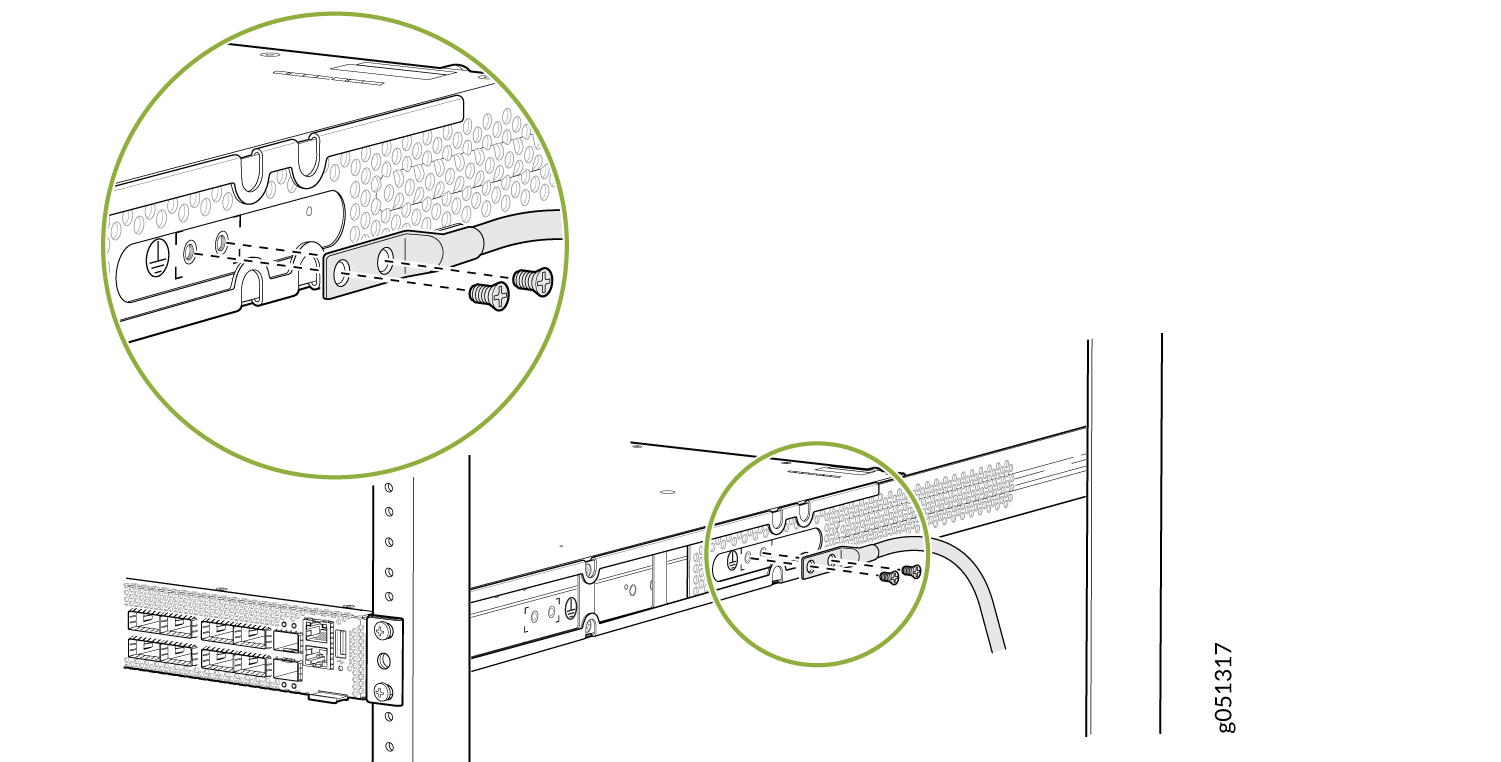
To ground the QFX5130-32CD/QFX5130E-32CD switch:
- Use the two 10-32 x 0.25-in. screws with number 10 split-lock washers to secure the grounding lug and the attached cable to the chassis. Attach the lug through the left-mounting bracket to the chassis. See Figure 1.Figure 1: Connect a Grounding Cable to a QFX5130-32CD/QFX5130E-32CD
Ground the QFX5130-48C/QFX5130-48CM Switch
To ground the QFX5130-48C/QFX5130-48CM switch:
Wrap and fasten one end of the electrostatic discharge (ESD) cable grounding strap around your bare wrist, and connect the other end to a site ESD point.
Connect the grounding cable to a proper earth ground, such as the rack in which you mount the device.
Secure the grounding cable terminal to the grounding bracket by using the 10-32 screws.
Loosen the two screws that are available on the chassis.
Place the bracket attached to the grounding cable over the grounding point.
Tighten the two screws.
- Figure 2: Ground the QFX5130-48C/QFX5130-48CM Switch
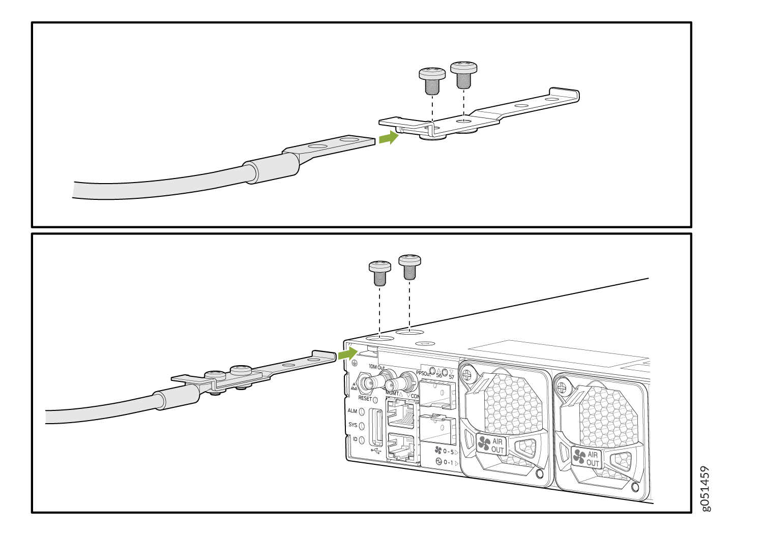
Dress the grounding cable. Ensure that the cable doesn’t block access to or come in contact with other device components. Also, ensure that the cable doesn’t drape where people could trip over it.
Connect AC Power to a QFX5130 Switch
Ensure that you have a power cord that is appropriate for your geographical location to connect AC power to the switch.
Before you begin connecting AC power to the switch:
Ensure that you have taken the necessary precautions to prevent electrostatic discharge (ESD) damage (see https://www.juniper.net/documentation/us/en/hardware/juniper-safety-guide/)
Ensure that you have connected the switch chassis to earth ground.
CAUTION:Before you connect power to the switch, a licensed electrician must attach a cable lug to the grounding and power cables that you supply. A cable with an incorrectly attached lug can damage the switch (for example, by causing a short circuit).
To meet safety and electromagnetic interference (EMI) requirements and to ensure proper operation, you must connect the chassis to earth ground before you connect it to power. For installations that require a separate grounding conductor to the chassis, use the protective earthing terminal on the switch chassis to connect to the earth ground. The switch gains additional grounding when you plug the power supply in the switch into a grounded AC power outlet by using the AC power cord appropriate for your geographical location. See AC Power Cord with Type C15 Coupler Specifications.
Install the power supplies in the chassis. For instructions on how to install a power supply in a QFX5130, see Install an AC Power Supply Unit in QFX5130 Switches.
The QFX5130 switch ships from the factory with two power supplies. Each power supply is a hot-removable and hot-insertable field-replaceable unit (FRU). You can install a replacement power supply in the slots next to the fan modules without powering off the switch or disrupting the switching function.
Each power supply must be connected to a dedicated power source outlet.
To connect AC power to a QFX5130 Switch:
- Locate the power cords shipped with the switch; the cords have plugs appropriate for your geographical location. See AC Power Cord with Type C15 Coupler Specifications .
For each power supply:
- Ensure that the loop on the power cord retainer is open and there is enough space to insert the power cord coupler into the inlet. If the loop is closed, press the small tab on the retainer to loosen the loop. See Figure 3.Figure 3: Attach the Power Cord Retainer
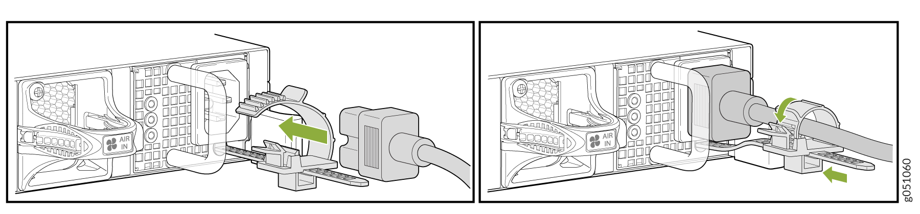
Warning:Ensure that the power cord does not block access to device components or drape where people could trip over it.
- Ensure that the loop on the power cord retainer is open and there is enough space to insert the power cord coupler into the inlet. If the loop is closed, press the small tab on the retainer to loosen the loop. See Figure 3.
Connect DC Power to a QFX5130 Switch
Before You Begin
Before you connect DC power to the switch:
Ensure that you have taken the necessary precautions to prevent electrostatic discharge (ESD) damage (see https://www.juniper.net/documentation/us/en/hardware/juniper-safety-guide/).
Ensure you have connected the switch chassis to earth ground.
CAUTION:Before you connect power to the switch, a licensed electrician must attach a cable lug to the ground and power cables that you supply (for example, by causing a short circuit).
To meet safety and electromagnetic interference (EMI) requirements and to ensure proper operation, you must connect the chassis to earth ground before you connect it to power. For installations that require a separate grounding conductor to the chassis, use the protective earthing terminal on the switch chassis to connect to earth ground.
Install the power supply in the chassis. For instructions on how to install a power supply in a QFX5130 switch, see Install an AC Power Supply Unit in QFX5130 Switches.
Warning:DC-powered QFX5130 switches are intended for installation only in a restricted-access location.
Ensure that you have the following parts and tools available:
A spare JPSU-1600W-1UDCAFI or JPSU-1600W-1UDCAFO for QFX5130 (not provided)
Phillips (+) screwdriver, number 2 (not provided)
Multimeter (not provided)
DC power source cables 10-12 AWG (not provided)
Ring lug - KST P/N: RNYBS8-4 or equivalent (not provided)
Connect DC Power to a QFX5130 Switch
To connect DC power to the DC model of a QFX5130 Switch:
- Install heat-shrink tubing insulation around the power cables.
To install heat-shrink tubing:
Slide the tubing over the portion of the cable where it is attached to the lug barrel. Ensure that the tubing covers the end of the wire and the barrel of the lug attached to it.
Shrink the tubing with a heat gun. Ensure that you heat all the sides of the tubing evenly so that it shrinks around the cable tightly.
Figure 4 shows the steps to install a heat-shrink tubing.
Note:Do not overheat the tubing.
Figure 4: Install Heat-Shrink Tubing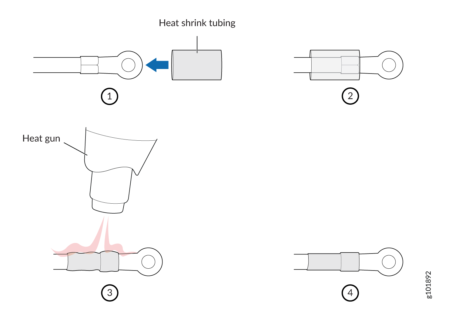
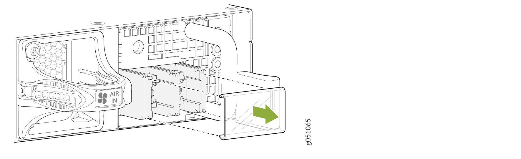
- Remove the terminal block cover. The terminal block cover is a piece of clear plastic that snaps into place over the terminal block (see Figure 5).Figure 5: Remove Terminal Block Cover
- Remove the screws on the terminals by using the screwdriver. Save the screws. See Figure 6.Figure 6: QFX5130 Faceplate
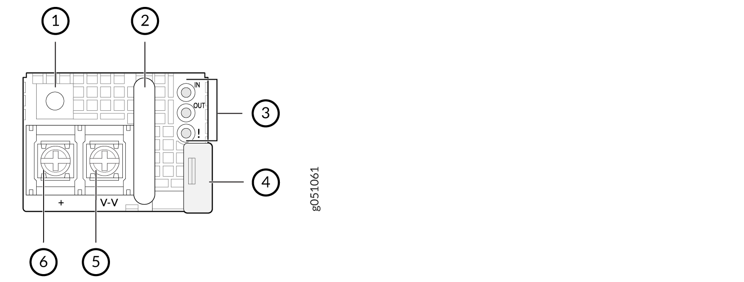 1—
1—Not used
4—Release latch
2—Handle
5—V– terminal
3—LEDs
6—V+ terminal
- Connect each power supply to the power sources. Secure the power source cables to the power supplies by screwing the ring lugs attached to the cables to the appropriate terminals by using the screw from the terminals (see Figure 7).Figure 7: Secure Ring Lugs to the Terminals on the QFX5130 DC Power Supply
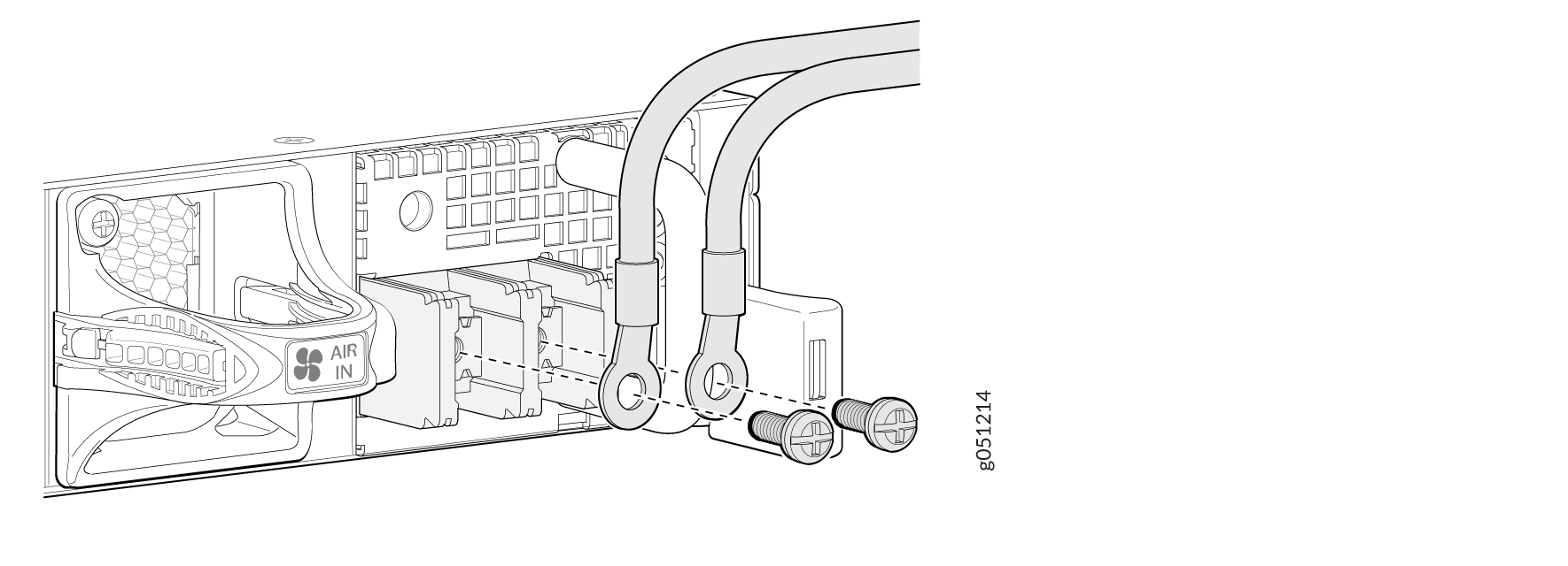
The QFX5130 Switch operates with a DC power supply that has a single, non-redundant feed input. For source redundancy, you must install two DC power supplies in the QFX5130 Switch—connect source (A) to one power supply and connect source (B) to the second power supply. This configuration provides the commonly deployed A/B feed redundancy for the system.
CAUTION:The connection between each power source and power supply must include a circuit breaker.
Do not connect two sources to a single power supply because doing so can potentially cause circulating current in feed wires whenever there is any difference in the voltage of the two sources.
- Secure the ring lug of the positive (+) DC power source cable to the V+ terminal on the DC power supply.
- Secure the ring lug of the negative (–) DC power source cable to the V– terminal on the DC power supply.
- Tighten the screws on the power supply terminals until snug by using a screwdriver. Do not overtighten—apply between 5 in-lb (0.56 Nm) and 6 in-lb (0.68 Nm) of torque to the screws.
Warning:Ensure that the power cables do not block access to device components or drape where people could trip over them.