QFX5120 System Overview
QFX5120 Switches Hardware Overview
The QFX5120 line of switches delivers low latency, flexible deployment options, and rich automation features. QFX5120 Switches build a strong underlay foundation for flexible, high-performance, standards-based fabrics and routing that improve network reliability and agility.
The QFX5120 switch is available in four models—QFX5120-32C, QFX5120-48T, QFX5120-48Y, and QFX5120-48YM. Each model is available in two variants featuring AC power supplies with front-to-back or back-to-front airflow and two models featuring DC power supplies with front-to-back or back-to-front airflow.
In addition to the device CLI, the QFX5120 can be managed and monitored by using Juniper Routing Director (formerly Juniper Paragon Automation) or Juniper Paragon Automation.
For a brief overview of the QFX5120-48T switch, see:
For a brief overview of the QFX5120-48Y switch, see:
For a brief overview of the QFX5120-48YM switch, see:
- Benefits of the QFX5120 Switch
- System Software and Hardware and Software Features
- Channelization in QFX5120 Switches
- Components on the Front and Rear Panels
- Virtual Chassis
- QFX5120 Cooling System
- QFX5120 Power System
Benefits of the QFX5120 Switch
EVPN-VXLAN architecture - QFX5120 Switches support IP fabrics with EVPN-VXLAN overlays, enabling Layer 2/3 network virtualization.
Hop-by-hop encryption - QFX5120-48YM supports IEEE 802.1AE MACsec AES-256 on all ports to help secure data center and Ethernet-based DCI/WAN deployments.
Synchronization services – Support for PTP enables QFX5120 to meet the requirements of the financial services industry (FSI) and the broadcasting media industry.
Industry-leading wire speeds—QFX5120 switches offer 25-Gbps and 100-Gbps wire speeds.
Support for channelization—You can channelize the QSFP28 ports and increase the number of interfaces.
Support for Virtual Chassis—All QFX5120 switch models support Virtual Chassis technology. You can interconnect up to two QFX5120-32C, QFX5120-48T, or QFX5120-48Y, or up to four QFX5120-48YM switches in a Virtual Chassis configuration.
System Software and Hardware and Software Features
Juniper Networks QFX Series Switches run Junos operating system (Junos OS), which provides Layer 2 and Layer 3 switching, routing, and security services. The first Junos OS release and hardware and software features supported on the models are listed in Table 1.
|
Switch Model |
First Junos OS Release Supported |
Hardware Features |
Aggregate Throughput (Bidirectional) |
Software Features |
|---|---|---|---|---|
|
QFX5120-32C |
Junos OS Release19.1R1 |
|
6.4 Tbps |
|
|
QFX5120-48T |
Junos OS Release20.2R1 |
|
2.16 Tbps |
|
|
QFX5120-48Y |
Junos OS Release18.3R1 |
|
4 Tbps |
|
|
QFX5120-48YM |
Junos OS Release20.4R1 |
|
4 Tbps |
Channelization in QFX5120 Switches
QFX5120 switches support channelization. You can channelize the 100GbE/40GbE quad small form-factor pluggable (QSFP28) ports into interfaces by connecting breakout cables and by using CLI configuration. Table 2 lists the channelization supported on the models.
|
Switch Model |
Ports |
Port Speed |
Supported Channelization |
For More Information |
|---|---|---|---|---|
|
QFX5120-32C |
0 through 30 |
40 Gbps |
Four 10GbE interfaces |
|
|
0 through 30 |
100 Gbps |
Four 25GbE interfaces |
||
|
0 through 31 Note:
The last 100GbE port (31) does not support 4x10GbE or 4x25GbE channelization options since the lanes are shared with the 10GbE SFP port. This port supports only 100GbE/40GbE and 2x50GbE channelization options. |
100 Gbps |
Two 50GbE interfaces |
||
|
QFX5120-48T |
50 and 51 |
40 Gbps |
Four 10GbE interfaces |
|
|
50 and 51 |
100 Gbps |
Four 25GbE interfaces |
||
|
48 through 53 |
100 Gbps |
Two 50GbE interfaces |
||
|
QFX5120-48Y |
48 through 55 |
40 Gbps |
Four 10GbE interfaces |
|
|
48 through 55 |
100 Gbps |
Four 25GbE interfaces |
||
|
QFX5120-48YM |
50 and 52 |
40 Gbps |
Four 10GbE interfaces |
|
|
50 and 52 |
100 Gbps |
Four 25GbE interfaces |
||
|
50 and 52 |
100 Gbps |
Two 50GbE interfaces |
Components on the Front and Rear Panels
QFX5120-32C Switches
Figure 1 shows the front view of the QFX5120-32C switch.
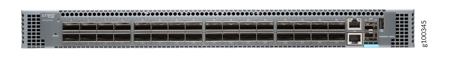
Figure 2 shows the rear view of the QFX5120-32C switch.
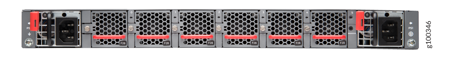
Figure 3 shows the components on the front panel of a QFX5120-32C switch.
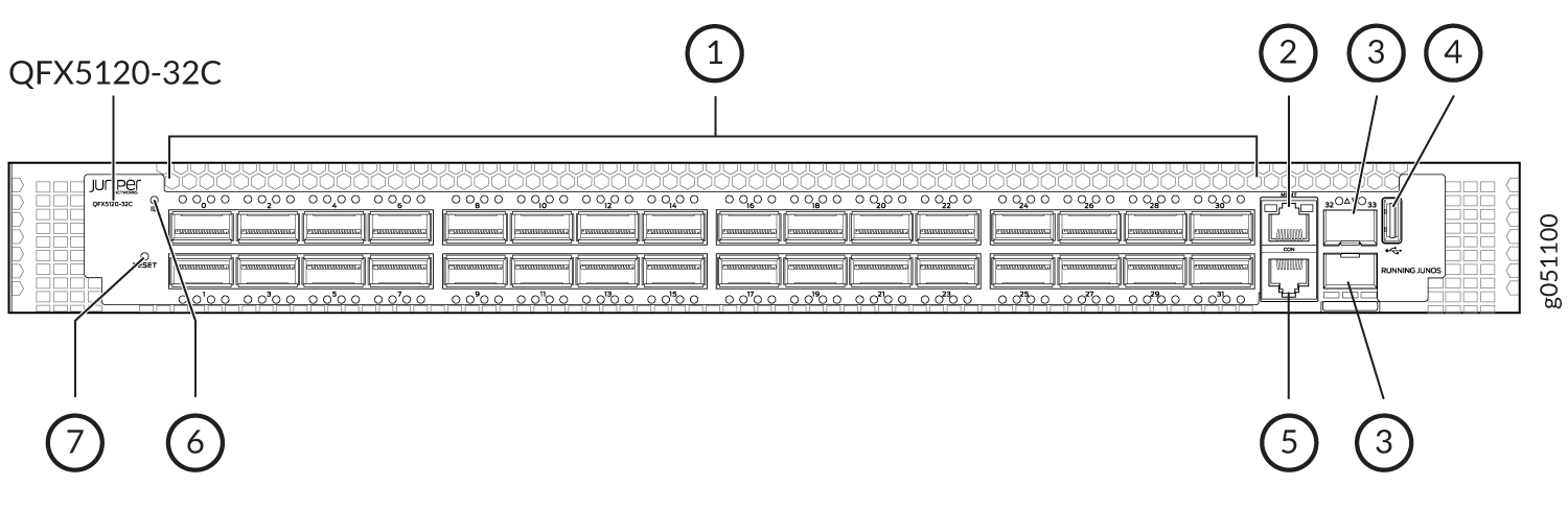
1 — QSFP28 ports | 5 — RJ-45 console port (labeled CON) |
2 — RJ-45 management port (labeled MGMT) | 6 — Chassis ID LED (labeled ID) |
3 — SFP+ ports | 7 — Reset button |
4 — USB port |
Figure 4 shows the components on the rear panel of a QFX5120-32C switch with AC power supplies.
1 — AC power supply | 3 — Fan module LEDs |
2 — Fan modules |
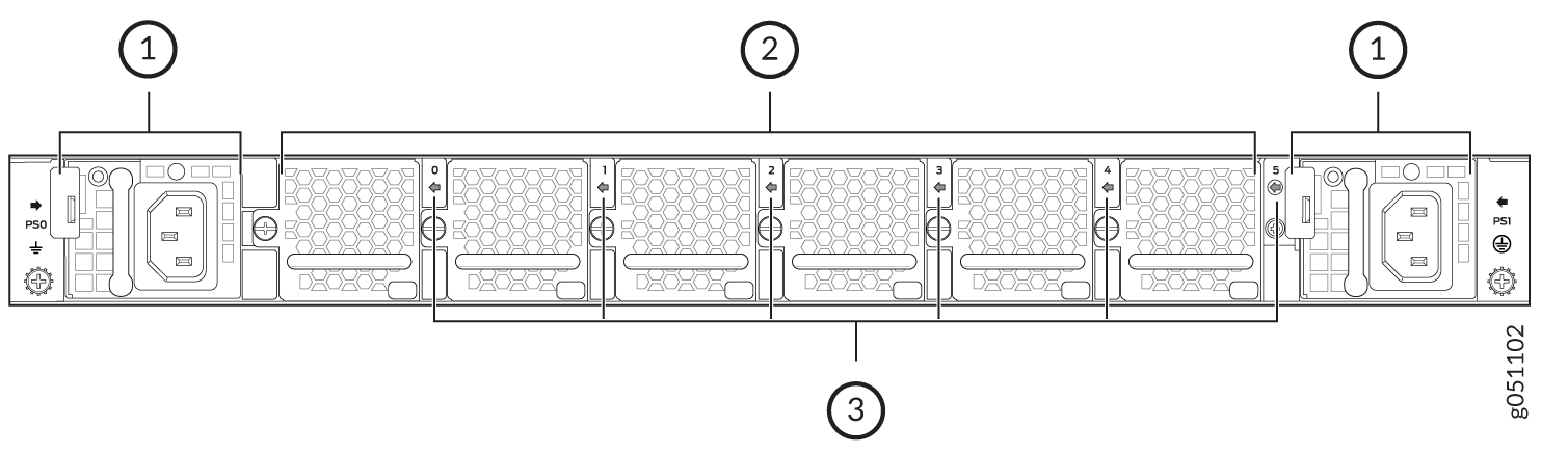
Figure 5 shows the components on the rear panel of a QFX5120-32C switch with DC power supplies.
1 — DC power supply | 3 — Fan module LEDs |
2 — Fan modules |
QFX5120-48T Switches
Figure 6 shows the front view of the QFX5120-48T switch.
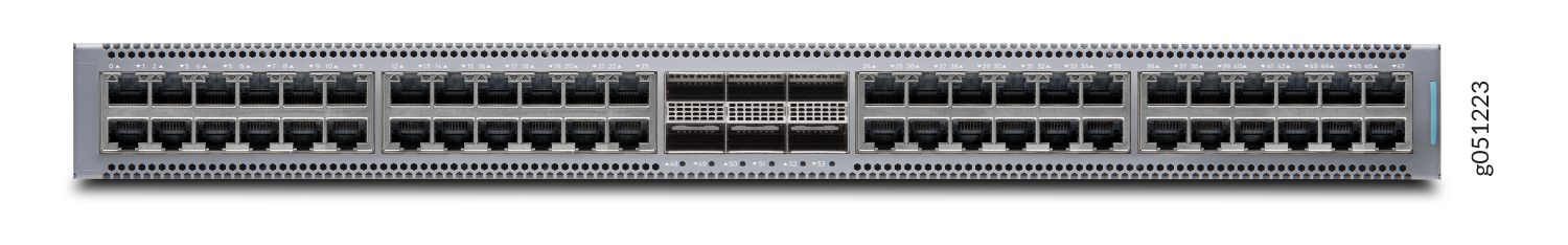
Figure 7 shows the rear view of the QFX5120-48T switch.
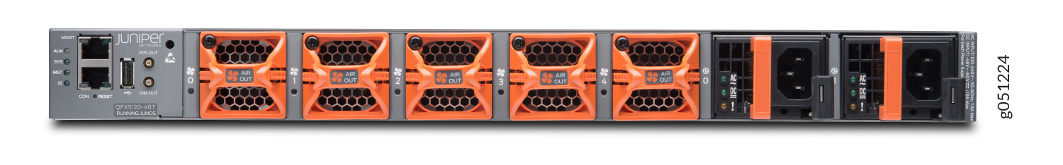
Figure 8 shows the components on the front panel of a QFX5120-48T switch.
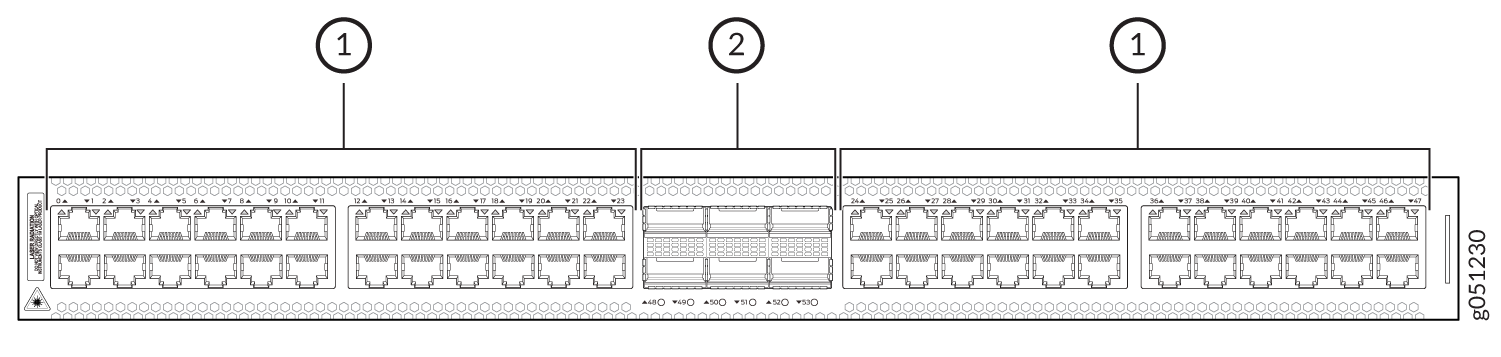
1 — 10-Gbps BASE-T ports | 2 — 100GbE/40GbE QSFP28 ports |
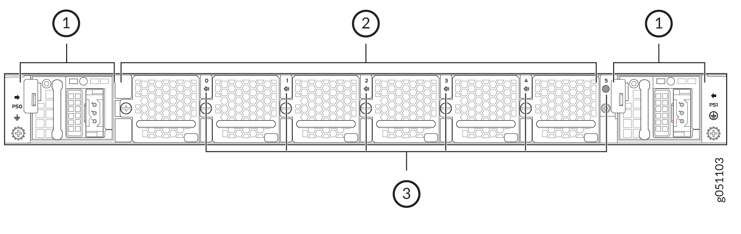
Figure 9 shows the components on the rear panel of a QFX5120-48T switch with AC power supplies.
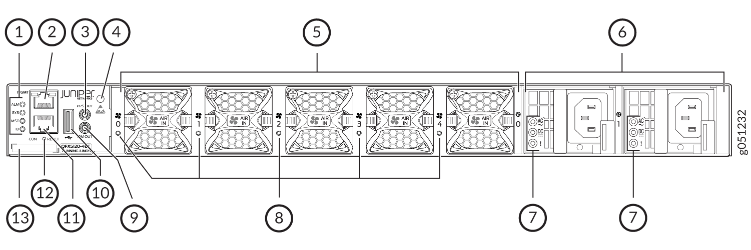
1 — Chassis status LEDs (labeled ALM, SYS, MST, and ID) | 8 — Fan module LEDs |
2 — RJ-45 management port (labeled MGMT) | 9 — 10M OUT port |
3 — PPS OUT port | 10 — USB port |
4 — ESD point | 11 — RJ-45 console port (labeled CON) |
5 — Fan modules | 12 — Reset button |
6 — AC power supplies | 13 — CLEI code label |
7 — AC power supply LEDs |
Figure 10 shows the components on the rear panel of a QFX5120-48T switch with DC power supplies.
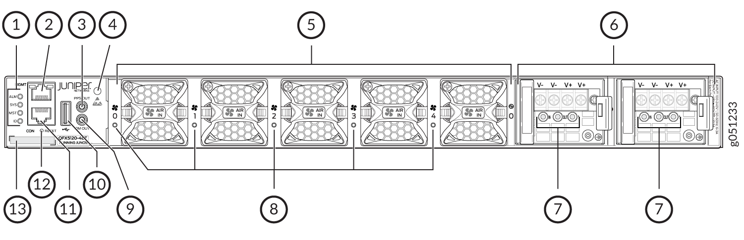
1 — Chassis status LEDs (labeled ALM, SYS, MST, and ID) | 8 — Fan module LEDs |
2 — RJ-45 management port | 9 — 10M OUT port |
3 — PPS OUT port | 10 — USB port |
4 — ESD point | 11 — RJ-45 console port |
5 — Fan modules | 12 — Reset button |
6 — DC power supplies | 13 — CLEI code label |
7 — DC power supply LEDs |
Figure 11 shows the components on the rear panel of a QFX5120-48T switch with high-voltage power supplies.
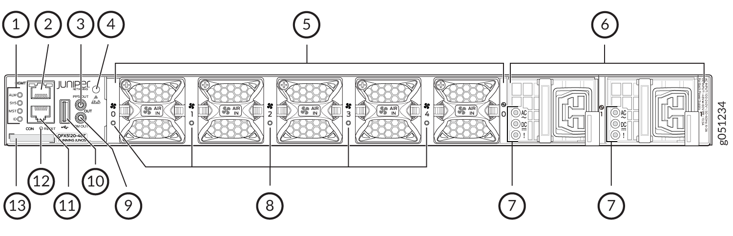
1 — Chassis status LEDs (labeled ALM, SYS, MST, and ID) | 8 — Fan module LEDs |
2 — RJ-45 management port | 9 — 10M OUT port |
3 — PPS OUT port | 10 — USB port |
4 — ESD point | 11 — RJ-45 console port |
5 — Fan modules | 12 — Reset button |
6 — High-voltage power supplies | 13 — CLEI code label |
7 — High-voltage power supply LEDs |
QFX5120-48Y Switches
Figure 12 shows the front view of the QFX5120-48Y switch.
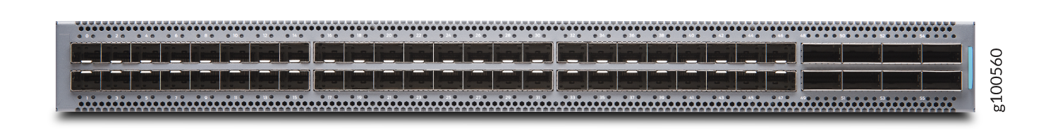
Figure 13 shows the rear view of the QFX5120-48Y switch.
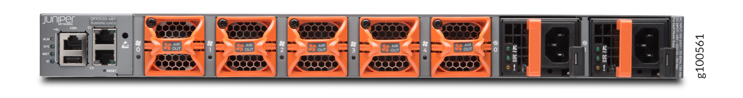
Figure 14 shows the components on the front panel of a QFX5120-48Y switch.
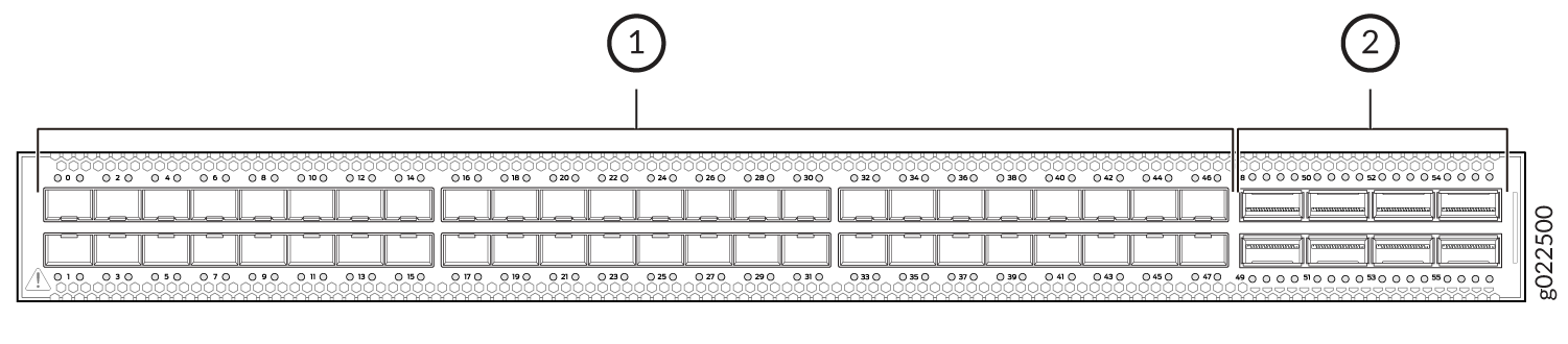
1 — SFP28 ports | 2 — QSFP28 ports |
-
The SFP28 ports are grouped in quads (groups of four) and you can configure the speed of the ports only in quads; you cannot configure the speed for a single SFP28 port.
-
The SFP28 ports can operate at 25-Gbps, 10-Gbps, or 1-Gbps speed, based on the configuration set at the quad level. The ports are configured to operate at 10-Gbps speed by default. If you need the ports to support the other speeds, you must configure those speeds.
When you use the latest OEM part number FCLF8521P2BTL (printed on the transceiver label), you can install 1GbE transceivers (such as QFX-SFP-1GE-T) in any port with no restrictions. The same applies for devices that support 10GbE copper transceivers. However, if you are using the older OEM part number SP7041-M1-JN (not shipped in last 3+ years) instead, do not install 1GbE copper transceivers (such as QFX-SFP-1GE-T) directly above or below another 1GbE copper transceiver. Use only the top row or bottom row to avoid damage to the device caused when the transceivers are installed above or below each other.
Figure 15 shows the components on the rear panel of a QFX5120-48Y switch with AC power supplies.
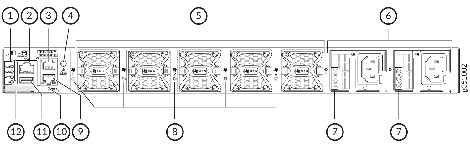
1 — Chassis status LEDs | 7 — Power supply LEDs |
2 — RJ-45 console port | 8 — Fan module LEDs |
3 — RJ-45 management port (labeled C1) | 9 — RJ-45 management port (labeled C0) |
4 — ESD point | 10 — Reset button |
5 — Fan modules | 11 — USB port |
6 — Power supplies | 12 — CLEI code label |
Figure 16 shows the components on the rear panel of a QFX5120-48Y switch with DC power supplies.
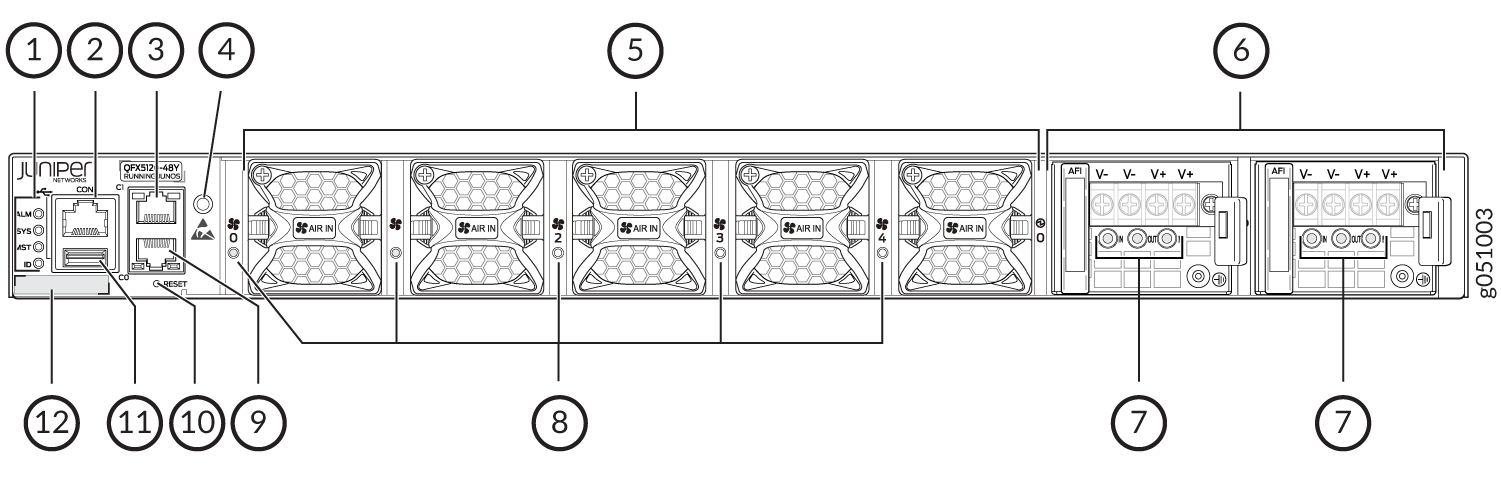
1 — Chassis status LEDs | 7 — Power supply LEDs |
2 — RJ-45 console port | 8 — Fan module LEDs |
3 — RJ-45 management port (labeled C1) | 9 — RJ-45 management port (labeled C0) |
4 — ESD point | 10 — Reset button |
5 — Fan modules | 11 — USB port |
6 — Power supplies | 12 — CLEI code label |
QFX5120-48YM Switches
Figure 17 shows the front view of the QFX5120-48YM switch.
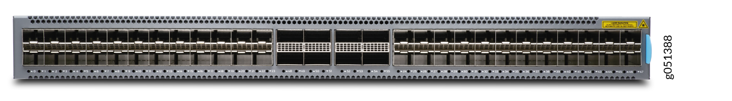
Figure 18 shows the rear view of the QFX5120-48YM switch.
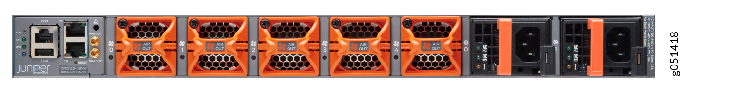
Figure 19 shows the components on the front panel of a QFX5120-48YM switch.
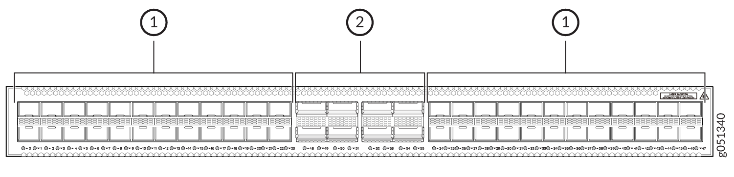
1 — SFP28 ports | 2 — QSFP28 ports |
-
The SFP28 ports are grouped in quads (groups of four) and you can configure the speed of the ports only in quads; you cannot configure the speed for a single SFP28 port.
-
The SFP28 ports can operate at 25-Gbps, 10-Gbps, or 1-Gbps speed, based on the configuration set at the quad level. The ports are configured to operate at 10-Gbps speed by default. If you need the ports to support the other speeds, you must configure those speeds.
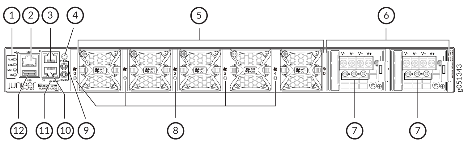
Figure 20 shows the components on the rear panel of a QFX5120-48YM switch with AC power supplies.
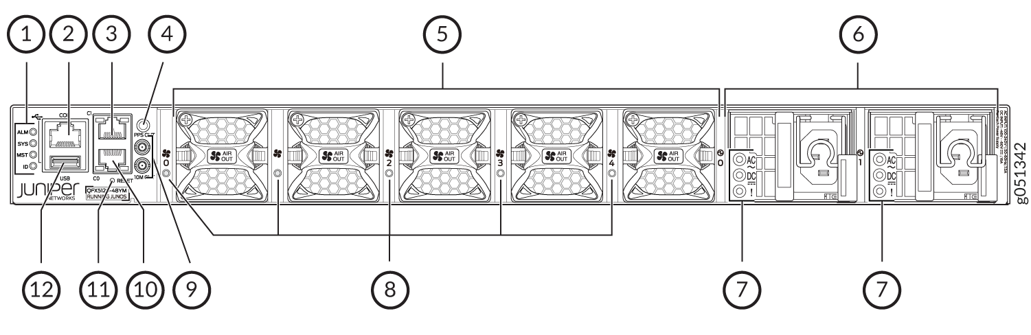
1 — Chassis status LEDs (labeled ALM, SYS, MST, and ID) | 7 — Power supply LEDs |
2 — RJ-45 console port | 8 — Fan module LEDs |
3 — RJ-45 management port (labeled C1) | 9 — 10M OUT and PPS OUT ports |
4 — ESD point | 10 — RJ-45 management port (labeled C0) |
5 — Fan modules | 11 — Reset button |
6 — Power supplies | 12 — USB port |
Figure 21 shows the components on the rear panel of a QFX5120-48YM switch with DC power supplies.
1 — Chassis status LEDs (labeled ALM, SYS, MST, and ID) | 7 — Power supply LEDs |
2 — RJ-45 console port | 8 — Fan module LEDs |
3 — RJ-45 management port (labeled C1) | 9 — 10M OUT and PPS OUT ports |
4 — ESD point | 10 — RJ-45 management port (labeled C0) |
5 — Fan modules | 11 — Reset button |
6 — Power supplies | 12 — USB port |
The CLEI code label is on the top panel of QFX5120-48YM switches, above the management ports. Figure 22 shows the location of the CLEI code label.
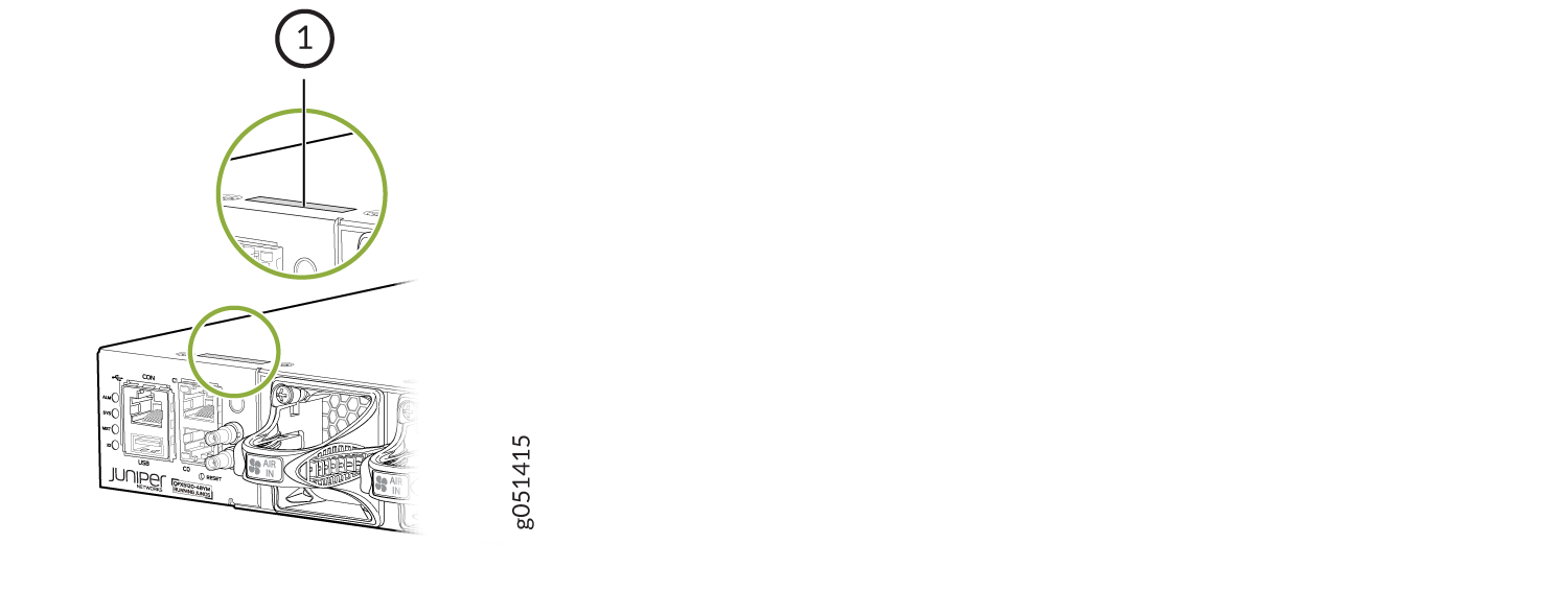
1 — CLEI code label |
Virtual Chassis
All QFX5120 switch models support Virtual Chassis technology. You can connect a QX5120 switch only with another QFX5120 switch of the same model in a Virtual Chassis configuration. QFX5120 switches do not have dedicated or default Virtual Chassis ports (VCPs). However, you can configure any of the QSFP28 ports as VCPs when those ports are not channelized. Table 3 lists the Junos OS release in which Virtual Chassis support is introduced and the QSFP28 ports that you can configure as VCPs.|
Model |
Support Introduced in Release |
Maximum Number of Switches in the Virtual Chassis |
Virtual Chassis Ports |
|---|---|---|---|
|
QFX5120-32C |
Junos OS Release 20.3R1 |
2 |
32 QSFP28 ports (0 through 31) |
|
QFX5120-48T |
Junos OS Release 20.2R1 |
2 |
6 QSFP28 ports (48 through 53) |
|
QFX5120-48Y |
Junos OS Release 19.3R1 |
2 |
8 QSFP28 ports (48 through 55) |
| QFX5120-48YM | Junos OS Release 23.1R1 | 4 | 8 QSFP28 ports (48 through 55) |
You configure, monitor, and maintain the QFX5120 Virtual Chassis the same way as you configure, monitor, and maintain a Virtual Chassis involving other QFX Series switches. See the following topics for more details on how to configure and change the members in a QFX5120 Virtual Chassis:
QFX5120 Cooling System
The cooling system in QFX5120 switches consists of fan modules and built-in fans in the power supplies. The airflow direction depends on the fan modules and power supplies installed in the switch. You can order a QFX5120 switch that supports front-to-back airflow (air enters through the front of the switch) or back-to-front airflow (air enters through the back of the switch).
The fan modules are hot-removable and hot-insertable field-replaceable units (FRUs) installed in the rear panel of the switch: You can remove and replace them without powering off the switch or disrupting switch functions.
QFX5120 Power System
QFX5120-32C, QFX5120-48T, and QFX5120-48Y switches support two 650-W AC or DC power supplies with front-to-back or back-to-front airflow. Additionally, QFX5120-48T switches support two 850-W high-voltage power supplies with AC or DC input and front-to-back or back-to-front airflow. QFX5120-48YM switches support two 850-W AC or DC power supplies with front-to-back or back-to-front airflow. Power supplies for the QFX5120 switch are fully redundant, load-sharing, and hot-removable and hot-insertable FRUs when the second power supply is installed and running. You can remove and replace them without powering off the switch or disrupting switch functions. Each power supply is cooled by its own internal cooling system. We ship QFX5120 switches with two AC or DC power supplies preinstalled in the rear panel of the chassis.
Do not mix:
-
AC and DC power supplies in the same chassis.
-
650-W and 850-W power supplies in the same QFX5120-48T chassis.
-
Power supplies with different airflow directions in the same chassis.
-
Fan modules with different airflow directions in the same chassis.
-
Power supplies and fan modules with different airflow directions in the same chassis.
If you install power supplies or fan modules with different airflow directions, Junos OS raises an alarm.
QFX5120 Switch Models and Variants
The QFX5120 has four models: QFX5120-32C, QFX5120-48T, QFX5120-48Y, and QFX5120-48YM. Each of these models has variants depending on power supply (AC or DC) and airflow (front-to-back or back-to-front). All variants of the QFX5120-32C switch ship with two power supplies and six fans installed by default. All variants of the QFX5120-48T, QFX5120-48Y, and QFX5120-48YM switches ship with two power supplies and five fans installed by default. Table 4 lists the components shipped with QFX5120 switch models and their variants.
Model Number |
Number of Ports and Their Types |
Power Supplies Shipped by Default |
Fan Modules Shipped by Default |
|---|---|---|---|
QFX5120-32C-AFO |
|
Two 650-W AC power supplies with front-to-back airflow, indicated by a red ejector lever. |
Six fan modules with front-to-back airflow, indicated by the label F2B and a red handle. |
QFX5120-32C-AFI |
|
Two 650-W AC power supplies with back-to-front airflow, indicated by a blue ejector lever. |
Six fan modules with back-to-front airflow, indicated by the label B2F and a blue handle. |
QFX5120-32C-DC-AFO |
|
Two 650-W DC power supplies with front-to-back airflow, indicated by a red ejector lever. |
Six fan modules with front-to-back airflow, indicated by the label F2B and a red handle. |
QFX5120-32C-DC-AFI |
|
Two 650-W DC power supplies with back-to-front airflow, indicated by a blue ejector lever. |
Six fan modules with back-to-front airflow, indicated by the label B2F and a blue handle. |
QFX5120-48T-AFO |
|
Two 650-W AC power supplies with front-to-back airflow, indicated by a Juniper Gold ejector lever. |
Five fan modules with front-to-back airflow, indicated by the label AIR OUT and a Juniper Gold handle. |
QFX5120-48T-AFI |
|
Two 650-W AC power supplies with back-to-front airflow, indicated by a Juniper Azure Blue ejector lever. |
Five fan modules with back-to-front airflow, indicated by the label AIR IN and a Juniper Azure Blue handle. |
QFX5120-48T-DC-AFO |
|
Two 650-W DC power supplies with front-to-back airflow, indicated by a Juniper Gold ejector lever. |
Five fan modules with front-to-back airflow, indicated by the label AIR OUT and a Juniper Gold handle. |
QFX5120-48T-DC-AFI |
|
Two 650-W DC power supplies with back-to-front airflow, indicated by a Juniper Azure Blue ejector lever. |
Five fan modules with back-to-front airflow, indicated by the label AIR IN and a Juniper Azure Blue handle. |
QFX5120-48Y-AFO2 |
|
Two 650-W AC power supplies with front-to-back airflow, indicated by a Juniper Gold ejector lever. |
Five fan modules with front-to-back airflow, indicated by the label AIR OUT and a Juniper Gold handle. |
QFX5120-48Y-AFI2 |
|
Two 650-W AC power supplies with back-to-front airflow, indicated by a Juniper Azure Blue ejector lever. |
Five fan modules with back-to-front airflow, indicated by the label AIR IN and a Juniper Azure Blue handle. |
QFX5120-48Y-DC-AFO2 |
|
Two 650-W DC power supplies with front-to-back airflow, indicated by a Juniper Gold ejector lever. |
Five fan modules with front-to-back airflow, indicated by the label AIR OUT and a Juniper Gold handle. |
QFX5120-48Y-DC-AFI2 |
|
Two 650-W DC power supplies with back-to-front airflow, indicated by a Juniper Azure Blue ejector lever. |
Five fan modules with back-to-front airflow, indicated by the label AIR IN and a Juniper Azure Blue handle. |
QFX5120-48YM-AFO |
|
Two 850-W AC power supplies with front-to-back airflow, indicated by a Juniper Gold ejector lever. |
Five fan modules with front-to-back airflow, indicated by the label AIR OUT and a Juniper Gold handle. |
QFX5120-48YM-AFI |
|
Two 850-W AC power supplies with back-to-front airflow, indicated by a Juniper Azure Blue ejector lever. |
Five fan modules with back-to-front airflow, indicated by the label AIR IN and a Juniper Azure Blue handle. |
QFX5120-48YM-DC-AO |
|
Two 850-W DC power supplies with front-to-back airflow, indicated by a Juniper Gold ejector lever. |
Five fan modules with front-to-back airflow, indicated by the label AIR OUT and a Juniper Gold handle. |
QFX5120-48YM-DC-AI |
|
Two 850-W DC power supplies with back-to-front airflow, indicated by a Juniper Azure Blue ejector lever. |
Five fan modules with back-to-front airflow, indicated by the label AIR IN and a Juniper Azure Blue handle. |
Do not mix:
AC and DC power supplies in the same chassis.
650-W and 850-W power supplies in the same QFX5120-48T chassis.
Power supplies with different airflow directions in the same chassis.
Fan modules with different airflow directions in the same chassis.
Power supplies and fan modules with different airflow directions in the same chassis.
QFX5120 Switch Hardware and CLI Terminology Mapping
This topic describes the hardware terms used in QFX5120 switch documentation and the corresponding terms used in the Junos OS CLI (see Table 5).
Hardware Item (CLI) |
Description (CLI) |
Value |
Item in Documentation |
Additional Information |
|---|---|---|---|---|
Chassis |
One of the following:
|
– |
Switch chassis |
|
Routing Engine (n) |
One of the following:
|
|
Routing Engine |
– |
FPC (n) |
Abbreviated name of the Flexible PIC Concentrator (FPC) One of the following:
|
|
In QFX5120, FPC refers to the switch itself. |
|
Xcvr (n) |
Abbreviated name of the transceiver |
n is a value equivalent to the number of the port in which the transceiver is installed. |
Optical transceivers |
|
Fan tray (n) |
QFX5120-32C |
Fan module |
||
One of the following:
|
n has a value 0 through 5, corresponding to the fan module slot number. |
|||
QFX5120-48T |
||||
One of the following:
|
n has a value 0 through 4, corresponding to the fan module slot number. |
|||
QFX5120-48Y |
||||
One of the following:
|
n has a value 0 through 4, corresponding to the fan module slot number. |
|||
QFX5120-48YM |
||||
One of the following:
|
n has a value 0 through 4, corresponding to the fan module slot number. |
|||
Power Supply (n) |
QFX5120-32C One of the following:
|
n has a value 0 through 1, corresponding to the power supply slot number. |
Power supply |
|
QFX5120-48T One of the following:
|
||||
QFX5120-48Y One of the following:
|
||||
QFX5120-48YM One of the following:
|
||||
Do not mix:
AC and DC power supplies in the same chassis.
650-W and 850-W power supplies in the same QFX5120-48T chassis.
Power supplies with different airflow directions in the same chassis.
Fan modules with different airflow directions in the same chassis.
Fan modules and power supplies with different airflow directions in the same chassis.