QFX5120 Power System
AC Power Supply in QFX5120 Switches
QFX5120-32C, QFX5120-48T, and QFX5120-48Y switches support two 650-W AC or DC power supplies. Additionally, QFX5120-48T switches support two 850-W high-voltage power supplies with AC or DC input. QFX5120-48YM switches support two 850-W AC or DC power supplies. The power supplies support front-to-back or back-to-front airflow. The power supplies are fully redundant, load-sharing, and hot-removable and hot-insertable FRUs when the second power supply is installed and running. You can remove and replace them without powering off the switch or disrupting switch functions. We ship QFX5120 switch models with two AC or DC power supplies preinstalled in the rear panel of the chassis. This topic describes the AC power supplies supported on QFX5120 switches.
Do not mix:
-
AC and DC power supplies in the same chassis.
-
650-W and 850-W power supplies in the same QFX5120-48T chassis.
-
Power supplies with different airflow directions in the same chassis.
-
Power supplies and fan modules with different airflow directions in the same chassis.
Characteristics of the AC Power Supply for QFX5120 Switches
You can install up to two power supplies in the power supply slots in the rear panel of the QFX5120 switch chassis. On QFX5120-32C switches, the slots are labeled PS0 and PS1. On QFX5120-48T, QFX5120-48Y, and QFX5120-48YM switches, the slots are labeled 0 and 1 and have a power icon next to them.
You must install both the power supplies for optimal functioning of the switch.
If the switch is operational while you are replacing power supplies, you must remove only one power supply at a time.
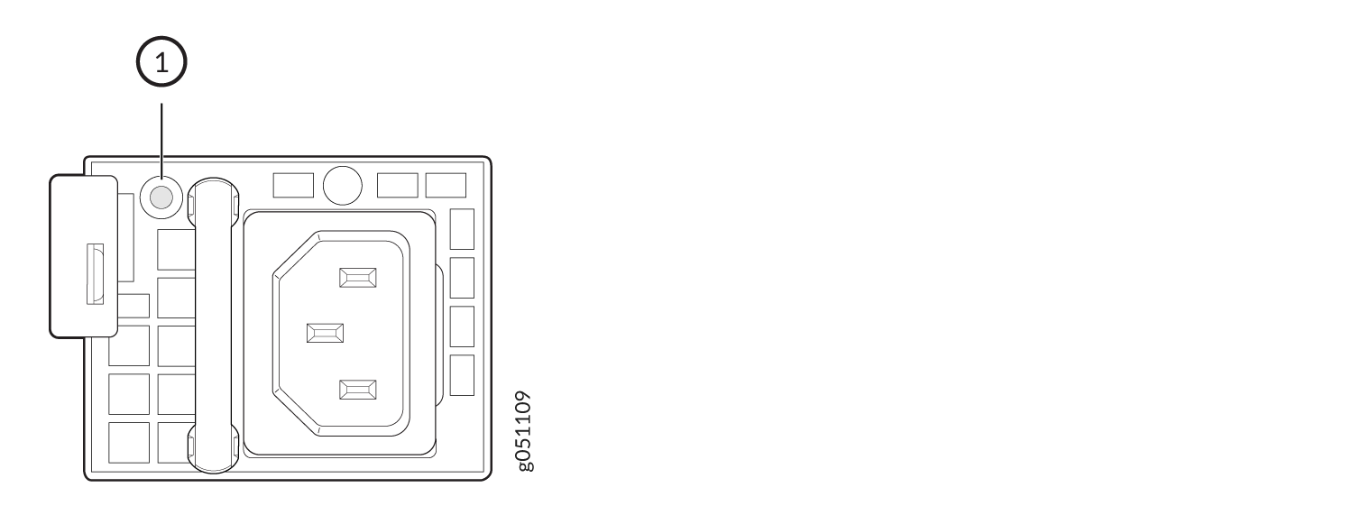
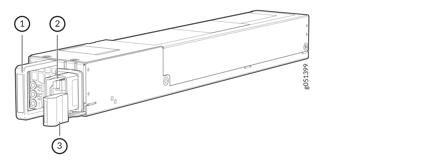
Figure 1 shows the AC power supply for a QFX5120-32C switch.
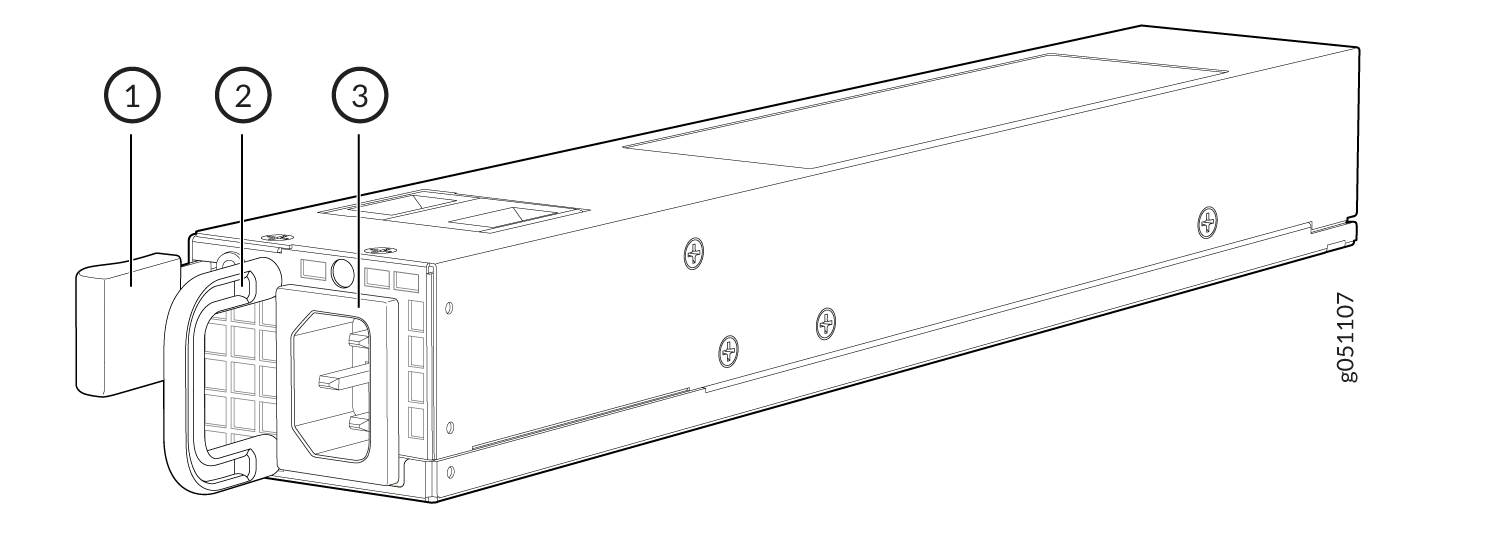
1 — Ejector lever | 3 — AC power cord inlet |
2 — Power supply handle |
Figure 2 shows the AC power supply for QFX5120-48T and QFX5120-48Y switches.
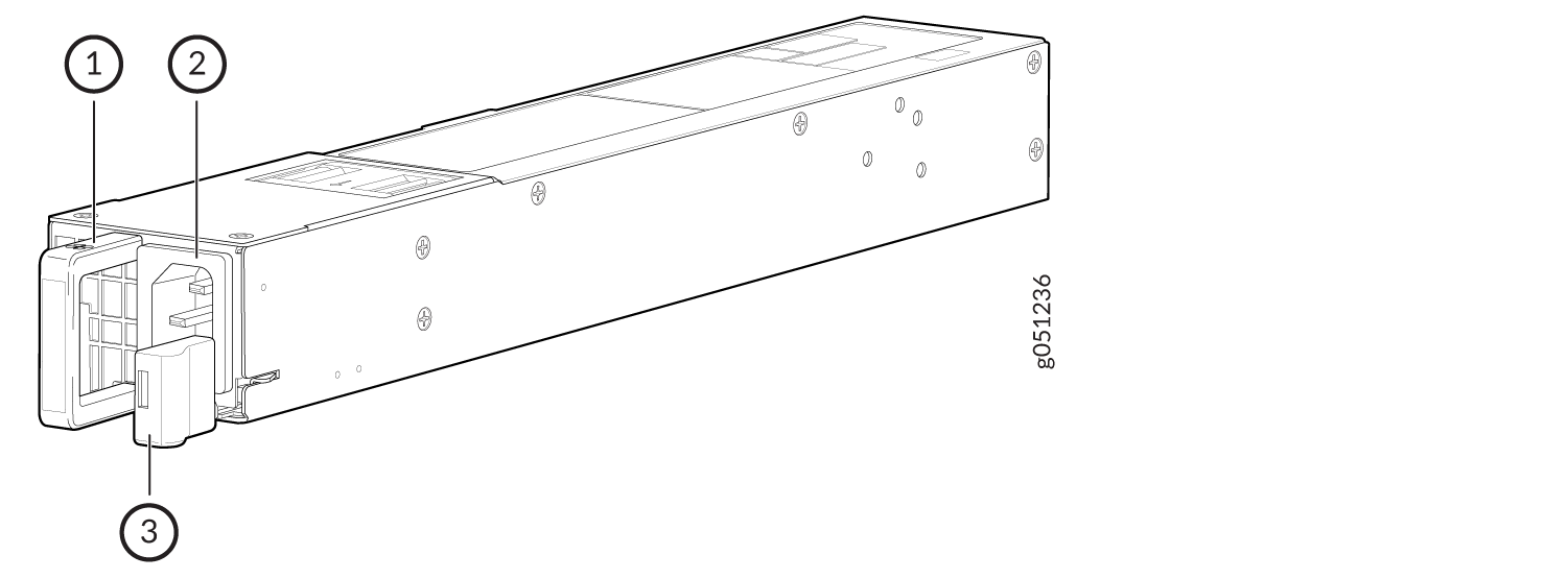
1 — Power supply handle | 3 — Ejector lever |
2 — AC power cord inlet |
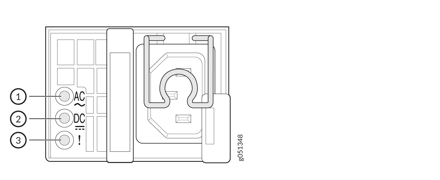
Figure 3 shows the AC power supply for QFX5120-48YM switches.
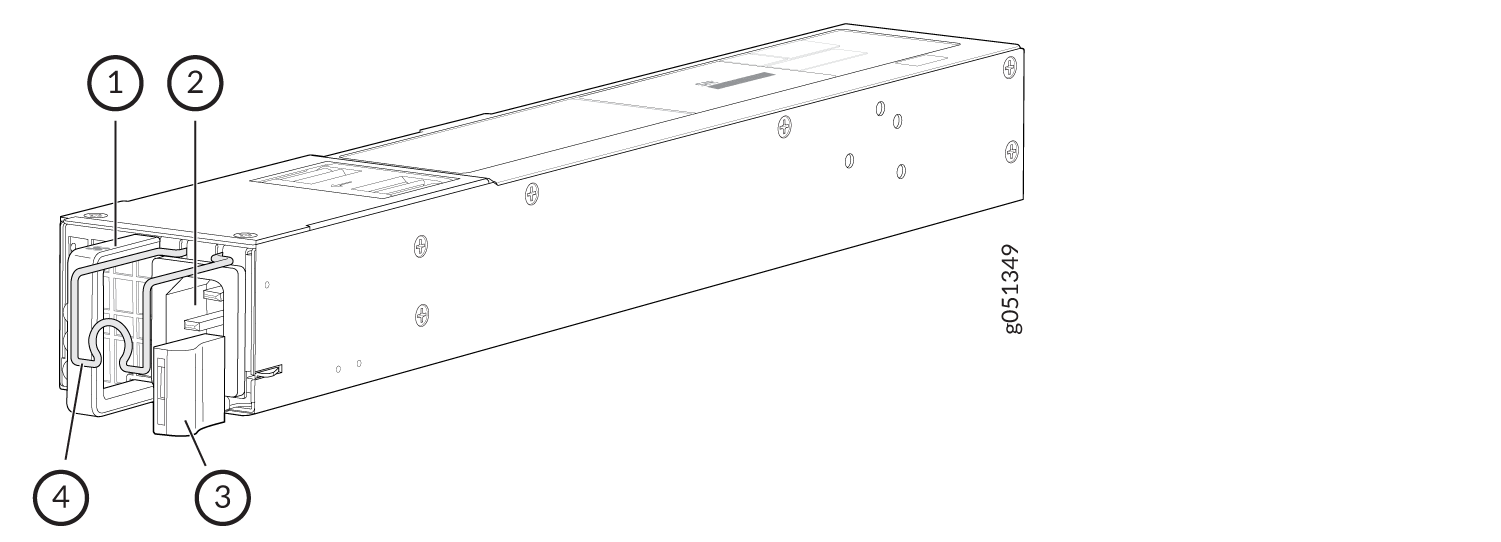
1 — Power supply handle | 3 — Ejector lever |
2 — AC power cord inlet | 4 — Power cord retainer |
Table 1 lists the specifications of the AC power supplies used in QFX5120 switches.
|
Item |
Specifications |
|---|---|
|
Model number |
|
|
Field-replaceable unit (FRU) type |
Hot-insertable and hot-removable |
|
Weight |
|
|
Minimum installed in chassis |
1 |
|
Maximum installed in chassis |
2 |
|
Power supply slots |
|
|
Airflow |
|
|
Status LEDs |
|
To prevent electrical injury while installing or removing AC power supplies, carefully follow instructions in Connect Power to an AC-Powered QFX5120 Switch and Maintain the QFX5120 Power System.
AC Power Supply Airflow
Each power supply is cooled by its own internal cooling system.
Verify that the airflow direction in the power supplies matches the airflow direction in the fan modules. Ensure that each power supply that you install in the chassis has the same airflow direction. If you install power supplies with two different airflow directions, Junos OS raises an alarm. If you need to convert the airflow direction in a chassis, you must replace all the fan modules and power supplies with the other airflow direction and update the installation base (see Register Products—Mandatory to Validate SLAs).
Table 2 lists the AC power supplies used in QFX5120 switches and the direction of airflow in them. The power supplies have color-coded handles and labels that indicate the direction of the airflow.
|
Power Supply |
Color of the Power Supply Handle |
Label |
Direction of Airflow |
|---|---|---|---|
|
QFX5120-32C—QFX520048Y-APSU-AO |
Red |
F2B |
Front-to-back—Cold air intake to cool the chassis is through the vents on the front panel of the chassis and hot air exhausts through the vents on the rear panel of the chassis. |
|
QFX5120-48T and QFX5120-48Y—JPSU-650W-AC-AO |
Juniper Gold |
AIR OUT |
|
|
QFX5120-48YM—JPSU-850W-AC-AFO |
Juniper Gold |
AIR OUT |
|
|
QFX5120-32C—QFX520048Y-APSU-AI |
Blue |
B2F |
Back-to-front—Cold air intake to cool the chassis is through the vents on the rear panel of the chassis and hot air exhausts through the vents on the front panel of the chassis. |
|
QFX5120-48T and QFX5120-48Y—JPSU-650W-AC-AI |
Juniper Azure Blue |
AIR IN |
|
|
QFX5120-48YM—JPSU-850W-AC-AFI |
Juniper Azure Blue |
AIR IN |
Power Supply Specifications for AC Power Supplies for QFX5120 Switches
QFX5120-32C, QFX5120-48T, and QFX5120-48Y switches support 650-W AC or DC power supplies. Additionally, QFX5120-48T switches support two 850-W high-voltage power supplies with AC or DC input. QFX5120-48YM switches support two 850-W AC or DC power supplies.
Table 3 shows the power supply specifications for AC power supplies for QFX5120-32C switches.
Item |
Specification |
|---|---|
AC input voltage |
Operating range: 100 VAC through 240 VAC |
AC input line frequency |
50–60 Hz |
AC input current rating |
|
Typical power consumption |
173 W |
Maximum power consumption |
365 W |
The maximum power consumption values specified here assumes 3.5W power per 100G optical module used.
Table 4 shows the power supply specifications for AC power supplies for QFX5120-48T switches.
Item |
Specification |
|---|---|
AC input voltage |
Operating range: 100 VAC through 240 VAC |
AC input line frequency |
50–60 Hz |
AC input current rating |
5 A at 100–240 VAC |
Typical power consumption |
202 W |
Maximum power consumption |
251 W |
Table 5 shows the power supply specifications for AC power supply for QFX5120-48Y switches.
Item |
Specification |
|---|---|
AC input voltage |
Operating range: 100 VAC through 240 VAC |
AC input line frequency |
50–60 Hz |
AC input current rating |
6 A at 100–240 VAC |
Typical power consumption |
155 W |
Maximum power consumption |
283 W |
Table 6 shows the power supply specifications for AC power supply for QFX5120-48YM switches.
Item |
Specification |
|---|---|
AC input voltage |
Operating range: 100 VAC through 240 VAC |
AC input line frequency |
50–60 Hz |
AC input current rating |
|
Typical power consumption |
280 W, 291 W with MACsec |
Maximum power consumption |
446 W, 460 W with MACsec |
Specifications of the Power Cord for AC Power Supplies for QFX5120 Switches
A detachable AC power cord is supplied with the AC power supplies. The coupler for AC power supplies is type C13 as described by International Electrotechnical Commission (IEC) standard 60320. The plug end of the power cord fits into the power source outlet that is standard for your geographical location.
The AC power cord provided with each power supply is intended for use with that power supply only and not for any other use.
In North America, AC power cords must not exceed 4.5 meters in length, to comply with National Electrical Code (NEC) Sections 400-8 (NFPA 75, 5-2.2) and 210-52 and Canadian Electrical Code (CEC) Section 4-010(3). The cords supplied with the switch are in compliance.
Table 7 lists the specifications of the AC power cord for the AC power supplies provided for the countries and regions listed in the table.
Country/Region |
Electrical Specifications |
Plug Standards |
Juniper Model Number |
|---|---|---|---|
Argentina |
250 VAC, 10 A, 50 Hz |
IRAM 2073 Type RA/3 |
CBL-EX-PWR-C13-AR |
Australia |
250 VAC, 10 A, 50 Hz |
AS/NZZS 3112 Type SAA/3 |
CBL-EX-PWR-C13-AU |
Brazil |
250 VAC, 10 A, 50 Hz |
NBR 14136 Type BR/3 |
CBL-EX-PWR-C13-BR |
China |
250 VAC, 10 A, 50 Hz |
GB 1002-1996 Type PRC/3 |
CBL-EX-PWR-C13-CH |
Europe (except Italy, Switzerland, and United Kingdom) |
250 VAC, 10 A, 50 Hz |
CEE (7) VII Type VIIG |
CBL-EX-PWR-C13-EU |
India |
250 VAC, 10 A, 50 Hz |
IS 1293 Type IND/3 |
CBL-EX-PWR-C13-IN |
Israel |
250 VAC, 10 A, 50 Hz |
SI 32/1971 Type IL/3G |
CBL-EX-PWR-C13-IL |
Italy |
250 VAC, 10 A, 50 Hz |
CEI 23-16 Type I/3G |
CBL-EX-PWR-C13-IT |
Japan |
125 VAC, 12 A, 50 Hz or 60 Hz |
JIS 8303 |
CBL-EX-PWR-C13-JP |
Korea |
250 VAC, 10 A, 50 Hz or 60 Hz |
CEE (7) VII Type VIIGK |
CBL-EX-PWR-C13-KR |
North America |
125 VAC, 13 A, 60 Hz |
NEMA 5-15 Type N5-15 |
CBL-EX-PWR-C13-US |
South Africa |
250 VAC, 10 A, 50 Hz |
SABS 164/1:1992 Type ZA/13 |
CBL-EX-PWR-C13-SA |
Switzerland |
250 VAC, 10 A, 50 Hz |
SEV 6534-2 Type 12G |
CBL-EX-PWR-C13-SZ |
Taiwan |
125 VAC, 11 A and 15 A, 50 Hz |
NEMA 5-15P Type N5-15P |
CBL-EX-PWR-C13-TW |
United Kingdom |
250 VAC, 10 A, 50 Hz |
BS 1363/A Type BS89/13 |
CBL-EX-PWR-C13-UK |
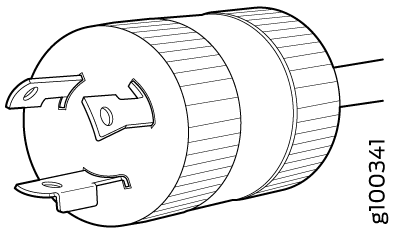
Figure 4 illustrates the plug on the power cord for the AC power supplies for a few of the countries or regions listed in Table 7.
LEDs on the AC Power Supplies Used in QFX5120 Switches
Figure 5 shows the LED on the AC power supply for QFX5120-32C switches.
1 — LED |
Table 8 describes the LED on the AC power supply for QFX5120-32C switches.
|
Color |
State |
Description |
|---|---|---|
|
Green |
On steadily |
The power supply is sending out power correctly. |
|
Blinking |
The power supply is in standby mode. |
|
|
Red |
On steadily |
An error is detected in the power supply. Replace the power supply as soon as possible. To maintain proper airflow through the chassis, leave the power supply installed in the chassis until you are ready to replace it. |
|
Blinking |
The internal fan in the power supply has failed. Replace the power supply as soon as possible. To maintain proper airflow through the chassis, leave the power supply installed in the chassis until you are ready to replace it. |
|
|
Unlit |
Unlit |
The power supply is disconnected from power, or the power supply is not receiving power. |
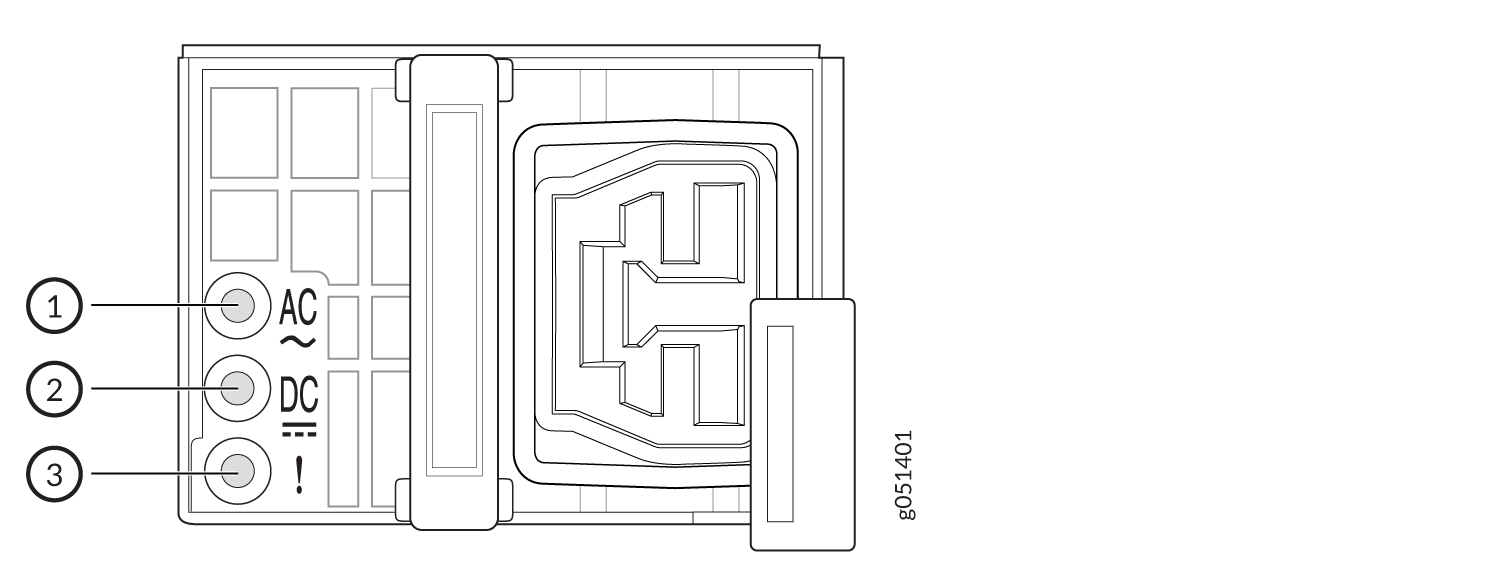
Figure 6 shows the LEDs on the AC power supply for QFX5120-48T and QFX5120-48Y switches. Figure 7 shows the LEDs on the AC power supply for QFX5120-48YM switches.
1 — AC LED (labeled AC) | 3 — Fault LED (labeled !) |
2 — DC LED (labeled DC) |
1 — AC LED (labeled AC) | 3 — Fault LED (labeled !) |
2 — DC LED (labeled DC) |
Table 9 describes the LEDs on the AC power supply for QFX5120-48T, QFX5120-48Y, and QFX5120-48YM switches.
|
LED Label |
Color |
State |
Description |
|---|---|---|---|
|
AC |
Green |
On steadily |
The power supply is receiving power. |
|
Unlit |
Unlit |
|
|
|
DC |
Green |
On steadily |
The power supply is sending out power correctly. |
|
Unlit |
Unlit |
|
|
|
! (Fault) |
Amber |
On steadily |
An error is detected in the power supply. Replace the power supply as soon as possible. To maintain proper airflow through the chassis, leave the power supply installed in the chassis until you are ready to replace it. |
DC Power Supply in QFX5120 Switches
QFX5120-32C, QFX5120-48T, and QFX5120-48Y switches support two 650-W AC or DC power supplies. Additionally, QFX5120-48T switches support 850-W high-voltage power supplies with AC or DC input. QFX5120-48YM switches support two 850-W AC or DC power supplies. The power supplies support front-to-back or back-to-front airflow. The power supplies are fully redundant, load-sharing, and hot-removable and hot-insertable FRUs when the second power supply is installed and running. You can remove and replace it without powering off the switch or disrupting switch functions. We ship QFX5120 switch models with two AC or DC power supplies preinstalled in the rear panel of the chassis. This topic describes the DC power supplies supported on QFX5120 switches.
Do not mix:
-
AC and DC power supplies in the same chassis.
-
650-W and 850-W power supplies in the same QFX5120-48T chassis.
-
Power supplies with different airflow directions in the same chassis.
-
Power supplies and fan modules with different airflow directions in the same chassis.
Characteristics of the DC Power Supply
You can install up to two power supplies in the power supply slots in the rear panel of the QFX5120 switch chassis. On QFX5120-32C switches, the slots are labeled PS0 and PS1. On QFX5120-48T, QFX5120-48Y, and QFX5120-48YM switches, the slots are labeled 0 and 1 and have a power icon next to them.
You must install both the power supplies for optimal functioning of the switch.
If the switch is operational while you are replacing power supplies, you must remove only one power supply at a time.
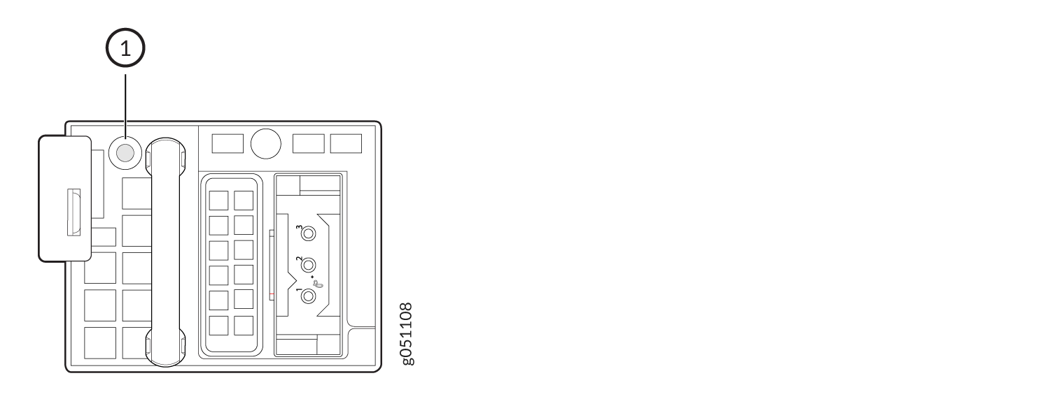
Figure 8 shows the DC power supply for a QFX5120-32C switch.
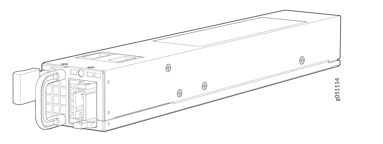
Figure 9 shows the faceplate of a DC power supply for QFX5120-32C switches.
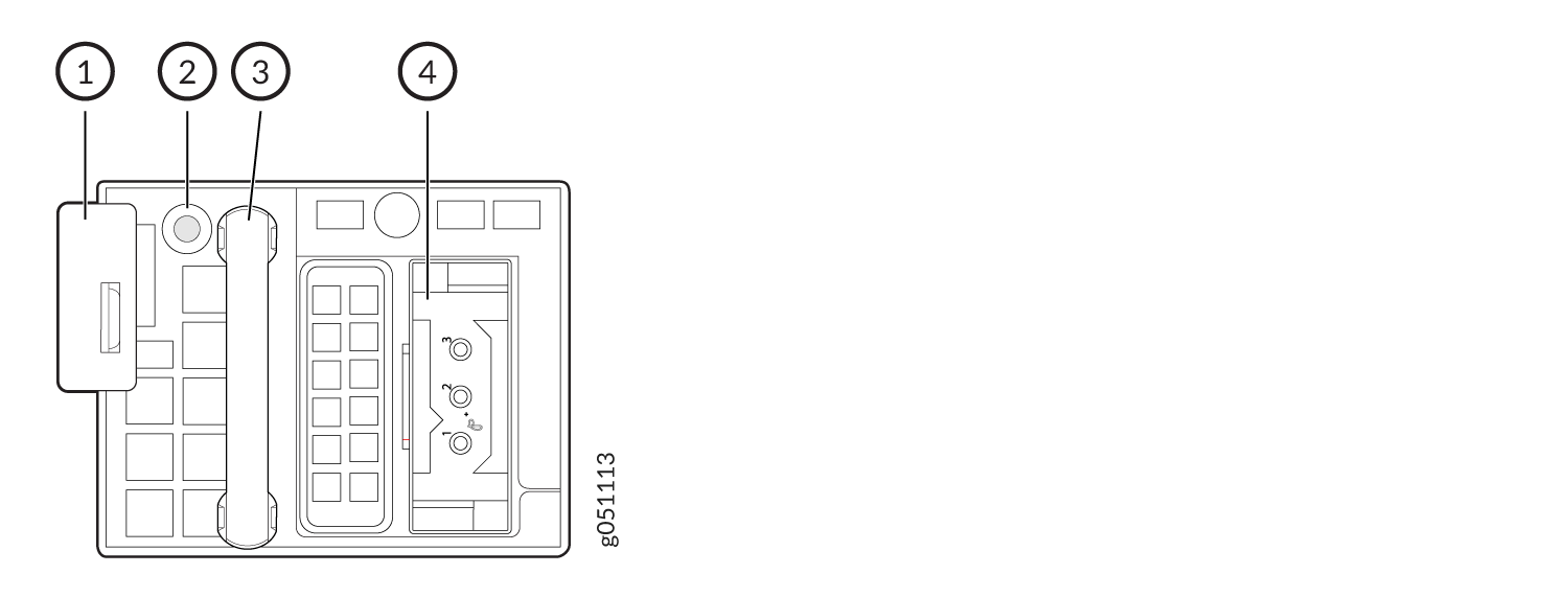
1 — Ejector lever | 3 — Power supply handle |
2 — LED | 4 — Input terminals |
Figure 10 shows the DC power supply for QFX5120-48T and QFX5120-48Y switches.
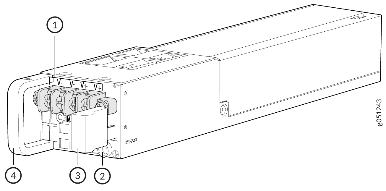
1 — Input terminals | 3 — Ejector lever |
2 — Protective earthing terminal | 4 — Power supply handle |
Figure 11 shows the DC power supply for QFX5120-48YM switches.
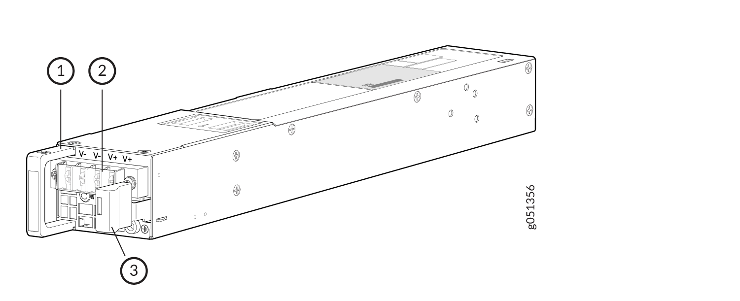
1 — Power supply handle | 3 — Ejector lever |
2 — Input terminals |
Figure 12 shows the faceplate of a DC power supply for QFX5120-48T, QFX5120-48Y, and QFX5120-48YM switches.
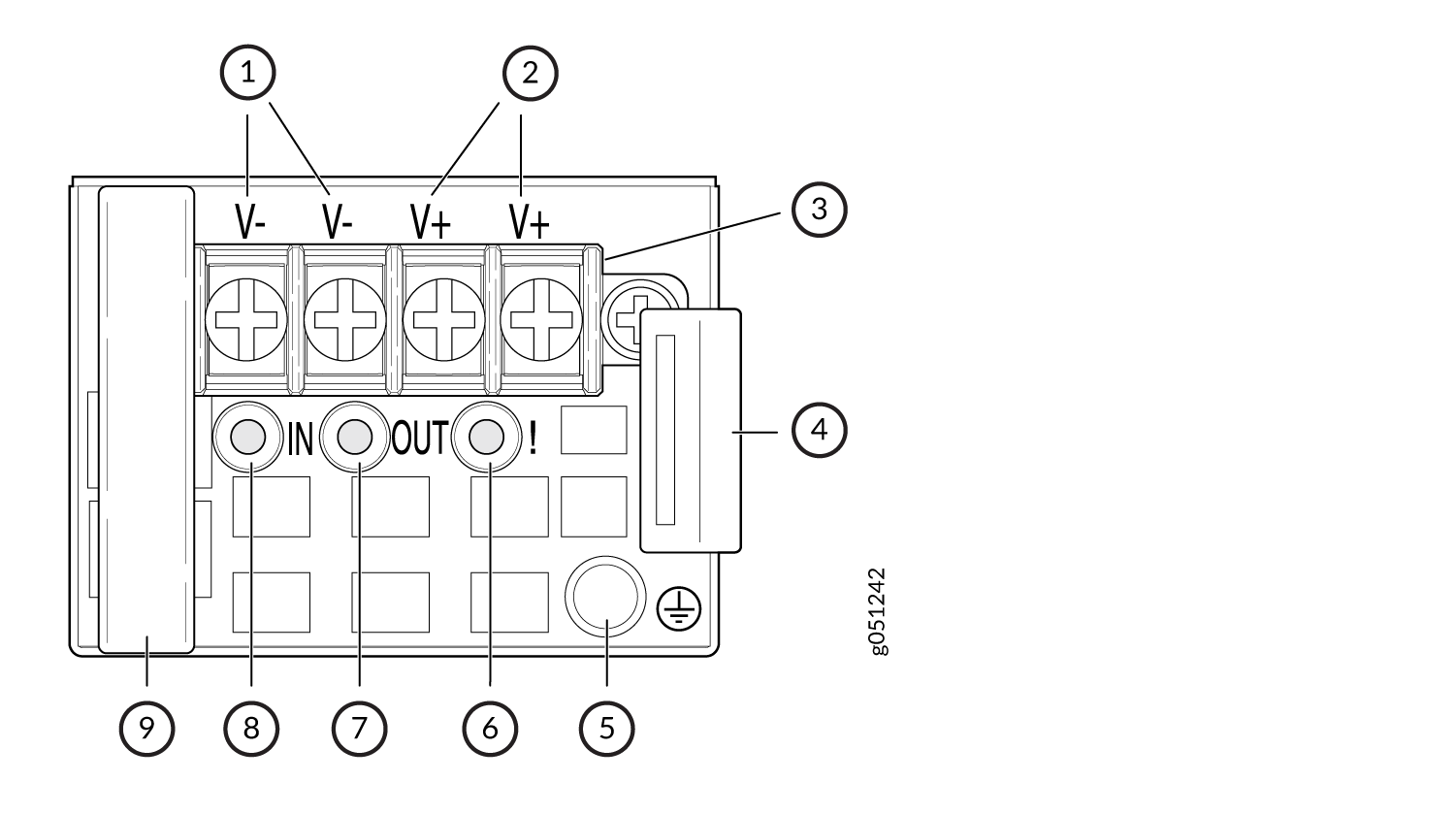
1 — Negative Input terminals | 6 — Fault LED (labeled !) |
2 — Positive Input terminals | 7 — Out LED (labeled OUT) |
3 — Terminal cover | 8 — In LED (labeled IN) |
4 — Ejector lever | 9 — Power supply handle |
5 — Protective earthing terminal |
Table 10 lists the specifications of the DC power supplies used in QFX5120 switches.
|
Item |
Specifications |
|---|---|
|
Model number |
|
|
Field-replaceable unit (FRU) type |
Hot-insertable and hot-removable |
|
Weight |
|
|
Minimum installed in chassis |
1 |
|
Maximum installed in chassis |
2 |
|
Power supply slots |
|
|
Fans |
Internal |
|
Airflow |
|
|
Power supply status LEDs |
|
To prevent electrical injury while installing or removing DC power supplies, carefully follow instructions in Connect Power to a DC-Powered QFX5120 Switch and Maintain the QFX5120 Power System.
DC Power Supply Airflow
Each power supply has its own fan and is cooled by its own internal cooling system.
Verify that the airflow direction in the power supplies matches the airflow direction in the fan modules. Ensure that each power supply that you install in the chassis has the same airflow direction. If you install power supplies with two different airflow directions, Junos OS raises an alarm. If you need to change the airflow direction in a chassis, you must replace all the fan modules and power supplies with the other airflow direction and update the installation base (see Register Products—Mandatory to Validate SLAs).
Table 11 lists the DC power supply models and the direction of airflow in them. The power supplies have color-coded handles and labels that indicate the direction of the airflow.
|
Model |
Color of the Power Supply Handle |
Label |
Direction of Airflow |
|---|---|---|---|
|
QFX5120-32C—QFX520048Y-DC-AFO |
Red |
F2B |
Front-to-back—Cold air intake to cool the chassis is through the vents on the front panel of the chassis and hot air exhausts through the vents on the rear panel of the chassis. |
|
QFX5120-48T and QFX5120-48Y—JPSU-650W-DC-AFO |
Juniper Gold |
AIR OUT |
|
|
QFX5120-48YM—JPSU-850W-DC-AFO |
Juniper Gold |
AIR OUT |
|
|
QFX5120-32C—QFX520048Y-DC-AFI |
Blue |
B2F |
Back-to-front—Cold air intake to cool the chassis is through the vents on the rear panel of the chassis and hot air exhausts through the vents on the front panel of the chassis. |
|
QFX5120-48T and QFX5120-48Y—JPSU-650W-DC-AFI |
Juniper Azure Blue |
AIR IN |
|
|
QFX5120-48YM—JPSU-850W-DC-AFI |
Juniper Azure Blue |
AIR IN |
Power Supply Specifications for DC Power Supplies for QFX5120 Switches
QFX5120-32C, QFX5120-48T, and QFX5120-48Y switches support 650-W AC or DC power supplies. Additionally, QFX5120-48T switches support two 850-W high-voltage power supplies with AC or DC input. QFX5120-48YM switches support two 850-W AC or DC power supplies.
Table 12 shows the power supply specifications for DC power supplies for QFX5120-32C switches.
Item |
Specifications |
|---|---|
DC input voltage |
|
DC input current rating |
16 A maximum |
Typical power consumption |
231 W |
Maximum power consumption |
493 W |
The maximum power consumption values specified here assumes 3.5W power per 100G optical module used.
Table 13 shows the power supply specifications for DC power supplies for QFX5120-48T switches.
Item |
Specifications |
|---|---|
DC input voltage |
|
DC input current rating |
10 A maximum |
Typical power consumption |
222 W |
Maximum power consumption |
227 W |
Table 14 shows the power supply specifications for DC power supplies for QFX5120-48Y switches.
Item |
Specifications |
|---|---|
DC input voltage |
|
DC input current rating |
10.5 A maximum |
Typical power consumption |
319 W |
Maximum power consumption |
342 W |
Table 15 shows the power supply specifications for DC power supplies for QFX5120-48YM switches.
Item |
Specifications |
|---|---|
DC input voltage |
|
DC input current rating |
16 A maximum |
Typical power consumption |
333 W |
Maximum power consumption |
356 W |
LEDs on the DC Power Supplies Used in QFX5120 Switches
Figure 13 shows the LED on the DC power supply for QFX5120-32C switches. Figure 14 shows the LEDs on the DC power supply for QFX5120-48T, QFX5120-48Y, and QFX5120-48YM switches.
1 — LED |
Table 16 describes the LED on the DC power supply for QFX5120-32C switches.
|
Color |
State |
Description |
|---|---|---|
|
Green |
On steadily |
The power supply is sending out power correctly. |
|
Blinking |
The power supply is in standby mode and is receiving power at +5 V. |
|
|
Alternating red/green |
Blinking |
Power supply warning. Check the logs for related messages. |
|
Red |
On steadily |
An error is detected in the power supply. Replace the power supply as soon as possible. To maintain proper airflow through the chassis, leave the power supply installed in the chassis until you are ready to replace it. |
|
Blinking |
The internal fan in the power supply has failed. Replace the power supply as soon as possible. To maintain proper airflow through the chassis, leave the power supply installed in the chassis until you are ready to replace it. |
|
|
Unlit |
Unlit |
The power supply is disconnected from power, or the power supply is not receiving power. |
1 — In LED (labeled IN) | 3 — Fault LED (labeled !) |
2 — Out LED (labeled OUT) |
The V+ terminals are shunted internally together, as are the V- terminals. You can wire the same polarity terminal together from the same source to provide an additional current path in a higher power chassis. Do not connect the terminals to different sources.
Table 17 describes the LEDs on the DC power supplies for QFX5120-48T, QFX5120-48Y, and QFX5120-48YM switches.
|
LED Label |
Color |
State |
Description |
|---|---|---|---|
|
IN |
Green |
On steadily |
The power supply is receiving power. |
|
Unlit |
Unlit |
The power supply is disconnected from power, or the power supply is not receiving power. |
|
|
OUT |
Green |
On steadily |
The power supply is sending out power correctly. |
|
Unlit |
Unlit |
The power supply is disconnected from power, or the power supply is not sending out power correctly. |
|
|
! (Fault) |
Amber |
On steadily |
An error is detected in the power supply. Replace the power supply as soon as possible. To maintain proper airflow through the chassis, leave the power supply installed in the chassis until you are ready to replace it. |
High-Voltage Power Supply for QFX5120-48T Switches
QFX5120 switches support two 650-W AC or DC power supplies with front-to-back or back-to-front airflow directions. Additionally, QFX5120-48T switches support two 850-W high-voltage power supplies with AC or DC input and front-to-back or back-to-front airflow. You must order a high-voltage power supply separately. Power supplies for the QFX5120 switch are fully redundant, load-sharing, and hot-removable and hot-insertable FRUs when the second power supply is installed and running. You can remove and replace them without powering off the switch or disrupting switch functions. We ship QFX5120 switch models with two AC or DC power supplies preinstalled in the rear panel of the chassis. This topic describes the high-voltage power supplies supported on QFX5120-48T switches.
Do not mix:
-
AC and DC power supplies in the same chassis.
-
650-W and 850-W power supplies in the same QFX5120-48T chassis.
-
Power supplies with different airflow directions in the same chassis.
-
Power supplies and fan modules with different airflow directions in the same chassis.
- Characteristics of the High-Voltage Power Supply for QFX5120-48T Switches
- High-Voltage Power Supply Airflow
- Power Supply Specifications for High-Voltage Power Supplies for QFX5120-48T switches
- Specifications of the Power Cord for High-Voltage Power Supply for QFX5120-48T Switches
- LEDs on the High-Voltage Power Supply Used in QFX5120-48T Switches
Characteristics of the High-Voltage Power Supply for QFX5120-48T Switches
QFX5120-48T switches support two high-voltage power supplies with AC or DC input and front-to-back or back-to-front airflow.
Figure 15 shows the high-voltage power supply for QFX5120-48T switches.
1 — Power supply handle | 3 — Ejector lever |
2 — Power cord inlet |
You can install up to two power supplies in the power supply slots in the rear panel of the QFX5120 switch chassis. On QFX5120-48T switches, the slots are labeled 0 and 1 and have a power icon next to them.
Table 18 lists the specifications of the high-voltage power supplies used in QFX5120-48T switches.
|
Item |
Specifications |
|
|---|---|---|
|
Model number |
QFX5120-48T: JPSU-850W-HV-AFO or JPSU-850W-HV-AFI |
|
|
Field-replaceable unit (FRU) type |
Hot-insertable and hot-removable |
|
|
Weight |
2.2 lb (1 kg) |
|
|
Minimum installed in chassis |
1 |
|
|
Maximum installed in chassis |
2 |
|
|
Power supply slots |
Slots labeled 0 and 1 with a power icon next to them in the rear panel of the chassis. |
|
|
Fans |
Internal |
|
|
Power supply status LEDs |
AC, DC, and ! (fault) |
|
To prevent electrical injury while installing or removing power supplies, carefully follow instructions in Connect Power to a QFX5120-48T Switch Powered by a High-Voltage Power Supply and Maintain the QFX5120 Power System.
High-Voltage Power Supply Airflow
Each power supply is cooled by its own internal cooling system.
The power supplies have color-coded handles that indicate the direction of the airflow. The Juniper Gold handles and AIR OUT label on the power supplies for QFX5120-48T switches indicate front-to-back airflow. The Juniper Azure Blue handles and AIR IN label on the power supplies for QFX5120-48T switches indicate back-to-front airflow.
Verify that the airflow direction in the power supplies matches the airflow direction in the fan modules. Ensure that each power supply that you install in the chassis has the same airflow direction. If you install power supplies with two different airflow directions, Junos OS raises an alarm. If you need to change the airflow direction in a chassis, you must replace all the fan modules and power supplies with the other airflow direction and update the installation base (see Register Products—Mandatory to Validate SLAs).
Table 19 lists the high-voltage power supplies used in QFX5120-48T switches and the direction of airflow in them.
|
Power Supply |
Direction of Airflow |
Color of the Power Supply Handle |
|---|---|---|
|
JPSU-850W-HV-AFO |
Front-to-back—cold air intake to cool the chassis is through the vents on the front panel of the chassis and hot air exhausts through the vents on the rear panel of the chassis. |
Juniper Gold |
|
JPSU-850W-HV-AFI |
Back-to-front—cold air intake to cool the chassis is through the vents on the rear panel of the chassis and hot air exhausts through the vents on the front panel of the chassis. |
Juniper Azure Blue |
Power Supply Specifications for High-Voltage Power Supplies for QFX5120-48T switches
Table 20 shows the power supply specifications for the high-voltage power supplies for QFX5120-48T switches operating with AC input.
|
Item |
Specification |
|---|---|
|
AC input voltage |
Operating range: 100 VAC through 277 VAC |
|
AC input line frequency |
50–60 Hz |
|
AC input current rating |
|
|
Typical power consumption |
290 W |
|
Maximum power |
440 W |
Table 21 shows the power supply specifications for the high-voltage power supplies for QFX5120-48T switches operating with DC input.
|
Item |
Specification |
|---|---|
|
DC input voltage |
Operating range: 240 VDC through 380 VDC |
|
DC input current rating |
4 A |
|
Typical power consumption |
290 W |
|
Maximum power |
440 W |
Specifications of the Power Cord for High-Voltage Power Supply for QFX5120-48T Switches
You can order a detachable power cord separately for your high-voltage power supplies. The plug or connector of the power cord fits into the power source outlet that is standard for your geographical location.
The power cord provided with each power supply is intended for use with that power supply only and not for any other use.
In North America, AC power cords must not exceed 4.5 meters in length, to comply with National Electrical Code (NEC) Sections 400-8 (NFPA 75, 5-2.2) and 210-52 and Canadian Electrical Code (CEC) Section 4-010(3). The cords supplied with the switch are in compliance.
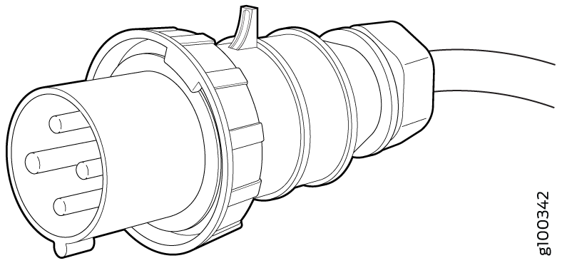
Table 22 lists the specifications of the power cord for the high-voltage power supplies provided for the countries and regions listed in the table.
|
Locale |
Cord Set Rating |
Plug Standards |
Spare Juniper Model Number |
Graphic |
|---|---|---|---|---|
|
Argentina |
16 A, 250 VAC |
IRAM 2073 Type RA/3 |
CBL-JNP-SG4-AR |
|
|
Australia and New Zealand |
15 A, 250 VAC |
AS/NZS 4417 |
CBL-JNP-SG4-AU |
|
|
Brazil |
16 A, 250 VAC |
NBR 14136 Type BR/3 |
CBL-JNP-SG4-BR |
|
|
China |
16 A, 250 VAC |
GB2099 |
CBL-JNP-SG4-CH |
|
|
Europe (except Italy, Switzerland, and United Kingdom) |
20 A, 250 VAC |
CEE 7/7 STRAIGHT |
CBL-JNP-SG4-EU |
|
|
Great Britain |
13 A, 250 VAC, |
BS1363 |
CBL-JNP-SG4-UK |
|
|
India |
16 A, 250 VAC |
SANS 164-1 |
CBL-JNP-SG4-SA |
|
|
Israel |
16 A, RA, 250 VAC |
SI 32/1971 Type IL/3G |
CBL-JNP-SG4-IL |
|
|
Italy |
16 A, 250 VAC |
CEI 23-16 |
CBL-JNP-SG4-IT |
|
|
North America |
16 A, 250 VAC |
Locking NEMA L6-20P |
CBL-JNP-SG4-US-L |
|
|
North America |
16 A, 250 VAC |
NEMA 6-20P |
CBL-JNP-SG4-US |
|
|
North America |
15 A, 277 V |
NEMA I7-20P |
CBL-JNP-SG4-HVAC |
|
|
North America |
20 A, 250 V |
IEC 320P6W |
CG_CBL-APP-400-02 |
|
|
South Africa |
16 A, 250 VAC |
SANS 164-1 |
CBL-JNP-SG4-SA |
|
|
Switzerland |
16 A, 250 VAC |
CEI 23-50 |
CBL-JNP-SG4-SZ |
|
|
All countries |
16 A, 400 VAC |
You can attach a plug as permitted by the local code. |
CBL-PWR2-BARE |
This bare cable is used for connecting to DC power input and is shipped without any lug attached. You can attach DC connector lugs as permitted by the local code. |
|
All countries |
16 A, 400 VAC |
You can attach a plug as permitted by the local code. |
CBL-PWR2-BARE-RA |
This bare cable is used for connecting to DC power input and is shipped without any lug attached. You can attach DC connector lugs as permitted by the local code. |
|
North America |
30 A, 400 VAC |
Both the ends of this cable have the same SAF-D-Grid connector. |
CBL-PWR-SG4 |
Both the ends of this cable have the same SAF-D-Grid connector. |
|
Europe |
16 A, 250 VAC |
IEC 316P6 |
CBL-JNP-SG4-316P6 |
|
|
North America and Canada |
20 A, 250 VAC |
IEC 320P6 |
CBL-JNP-SG4-320P6 |
|
LEDs on the High-Voltage Power Supply Used in QFX5120-48T Switches
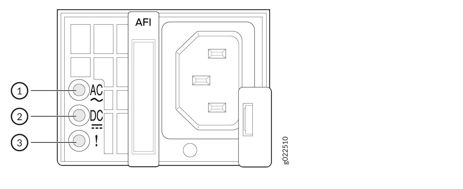
Figure 16 shows the location of the LEDs on the high-voltage power supply used in QFX5120-48T switches.
1 — AC LED (labeled AC ) | 3 — Fault LED (labeled !) |
2 — DC LED (labeled DC) |
Table 23 describes the LEDs on the high-voltage power supply used in QFX5120-48T switches.
|
LED Label |
Color |
State |
Description |
|---|---|---|---|
|
AC |
Green |
On steadily |
The power supply is receiving power. |
|
Unlit |
Unlit |
|
|
|
DC |
Green |
On steadily |
The power supply is sending out power correctly. |
|
Unlit |
Unlit |
|
|
|
! (Fault) |
Amber |
On steadily |
An error is detected in the power supply. Replace the power supply as soon as possible. To maintain proper airflow through the chassis, leave the power supply installed in the chassis until you are ready to replace it. |